EP1366836A1 - Self-piercing rivet setting apparatus - Google Patents
Self-piercing rivet setting apparatus Download PDFInfo
- Publication number
- EP1366836A1 EP1366836A1 EP03010633A EP03010633A EP1366836A1 EP 1366836 A1 EP1366836 A1 EP 1366836A1 EP 03010633 A EP03010633 A EP 03010633A EP 03010633 A EP03010633 A EP 03010633A EP 1366836 A1 EP1366836 A1 EP 1366836A1
- Authority
- EP
- European Patent Office
- Prior art keywords
- punch
- self
- die
- die assembly
- driving device
- Prior art date
- Legal status (The legal status is an assumption and is not a legal conclusion. Google has not performed a legal analysis and makes no representation as to the accuracy of the status listed.)
- Granted
Links
- 230000000149 penetrating effect Effects 0.000 claims description 4
- 230000007246 mechanism Effects 0.000 description 13
- 239000000463 material Substances 0.000 description 3
- XAGFODPZIPBFFR-UHFFFAOYSA-N aluminium Chemical compound [Al] XAGFODPZIPBFFR-UHFFFAOYSA-N 0.000 description 2
- 229910052782 aluminium Inorganic materials 0.000 description 2
- 230000008878 coupling Effects 0.000 description 2
- 238000010168 coupling process Methods 0.000 description 2
- 238000005859 coupling reaction Methods 0.000 description 2
- 230000009467 reduction Effects 0.000 description 2
- 229910000838 Al alloy Inorganic materials 0.000 description 1
- 230000004913 activation Effects 0.000 description 1
- 230000008901 benefit Effects 0.000 description 1
- 230000008859 change Effects 0.000 description 1
- 230000006866 deterioration Effects 0.000 description 1
- 238000010586 diagram Methods 0.000 description 1
- 230000002708 enhancing effect Effects 0.000 description 1
- 238000009434 installation Methods 0.000 description 1
- 238000000034 method Methods 0.000 description 1
- 230000008569 process Effects 0.000 description 1
- 238000007789 sealing Methods 0.000 description 1
- 230000035939 shock Effects 0.000 description 1
- 238000006467 substitution reaction Methods 0.000 description 1
- 239000013585 weight reducing agent Substances 0.000 description 1
- 238000003466 welding Methods 0.000 description 1
Images




Classifications
-
- B—PERFORMING OPERATIONS; TRANSPORTING
- B21—MECHANICAL METAL-WORKING WITHOUT ESSENTIALLY REMOVING MATERIAL; PUNCHING METAL
- B21J—FORGING; HAMMERING; PRESSING METAL; RIVETING; FORGE FURNACES
- B21J15/00—Riveting
- B21J15/10—Riveting machines
- B21J15/36—Rivet sets, i.e. tools for forming heads; Mandrels for expanding parts of hollow rivets
-
- B—PERFORMING OPERATIONS; TRANSPORTING
- B21—MECHANICAL METAL-WORKING WITHOUT ESSENTIALLY REMOVING MATERIAL; PUNCHING METAL
- B21J—FORGING; HAMMERING; PRESSING METAL; RIVETING; FORGE FURNACES
- B21J15/00—Riveting
- B21J15/10—Riveting machines
-
- B—PERFORMING OPERATIONS; TRANSPORTING
- B21—MECHANICAL METAL-WORKING WITHOUT ESSENTIALLY REMOVING MATERIAL; PUNCHING METAL
- B21J—FORGING; HAMMERING; PRESSING METAL; RIVETING; FORGE FURNACES
- B21J15/00—Riveting
- B21J15/02—Riveting procedures
- B21J15/025—Setting self-piercing rivets
-
- Y—GENERAL TAGGING OF NEW TECHNOLOGICAL DEVELOPMENTS; GENERAL TAGGING OF CROSS-SECTIONAL TECHNOLOGIES SPANNING OVER SEVERAL SECTIONS OF THE IPC; TECHNICAL SUBJECTS COVERED BY FORMER USPC CROSS-REFERENCE ART COLLECTIONS [XRACs] AND DIGESTS
- Y10—TECHNICAL SUBJECTS COVERED BY FORMER USPC
- Y10T—TECHNICAL SUBJECTS COVERED BY FORMER US CLASSIFICATION
- Y10T29/00—Metal working
- Y10T29/49—Method of mechanical manufacture
- Y10T29/49826—Assembling or joining
- Y10T29/49833—Punching, piercing or reaming part by surface of second part
- Y10T29/49835—Punching, piercing or reaming part by surface of second part with shaping
- Y10T29/49837—Punching, piercing or reaming part by surface of second part with shaping of first part
-
- Y—GENERAL TAGGING OF NEW TECHNOLOGICAL DEVELOPMENTS; GENERAL TAGGING OF CROSS-SECTIONAL TECHNOLOGIES SPANNING OVER SEVERAL SECTIONS OF THE IPC; TECHNICAL SUBJECTS COVERED BY FORMER USPC CROSS-REFERENCE ART COLLECTIONS [XRACs] AND DIGESTS
- Y10—TECHNICAL SUBJECTS COVERED BY FORMER USPC
- Y10T—TECHNICAL SUBJECTS COVERED BY FORMER US CLASSIFICATION
- Y10T29/00—Metal working
- Y10T29/53—Means to assemble or disassemble
- Y10T29/5343—Means to drive self-piercing work part
-
- Y—GENERAL TAGGING OF NEW TECHNOLOGICAL DEVELOPMENTS; GENERAL TAGGING OF CROSS-SECTIONAL TECHNOLOGIES SPANNING OVER SEVERAL SECTIONS OF THE IPC; TECHNICAL SUBJECTS COVERED BY FORMER USPC CROSS-REFERENCE ART COLLECTIONS [XRACs] AND DIGESTS
- Y10—TECHNICAL SUBJECTS COVERED BY FORMER USPC
- Y10T—TECHNICAL SUBJECTS COVERED BY FORMER US CLASSIFICATION
- Y10T29/00—Metal working
- Y10T29/53—Means to assemble or disassemble
- Y10T29/53709—Overedge assembling means
- Y10T29/5377—Riveter
Definitions
- the present invention relates to a self-piercing rivet setting apparatus using a self-piercing rivet having a large head and a hollow leg extending downward from the head to fasten a plurality of workpieces together, and in particular to a mechanism for changing dies to be used in the above apparatus.
- a self-piercing rivet is used to fasten two or more sheet members (or a sheet member and another component) together.
- a self-piercing rivet setting apparatus is disclosed in Japanese Patent Laid-Open Publication No. H 08-505087.
- a self-piercing rivet comprises a large diameter head (hereinafter, "large head") and a hollow leg extending downward from the head.
- large head a large diameter head
- the front end of the leg is expandingly deformed while piercing the workpieces, and the workpieces are finally fastened together by the deformed leg and the large head.
- the self-piercing rivet is driven into workpieces to penetrate through a punch-side workpiece but stay in a receiving-side workpiece adjacent to a die without penetrating therethrough.
- no opening is formed in the surface of the receiving-side workpiece, which provides an advantage of preventing deterioration in a sealing performance of the receiving-side workpiece while maintaining good appearance thereof.
- Fig. 1 is a sectional view showing a connected region of a pair of workpieces fastened by a conventional self-piercing rivet.
- the self-piercing rivet comprises a large head 5 and a hollow leg 6 extending downward from the head.
- the self-piercing rivet is driven into a pair of workpieces 2, 3 by a punch and a die of a rivet setting apparatus (not shown).
- the leg 6 is deformed to allow the front end thereof to be expanded while piercing the workpieces (body panels or the like).
- the punch-side workpiece 2 and the receiving-side workpiece 3 are fastened together by the deformed leg 6 and the large head 5.
- the pair of workpieces 2, 3 are fastened together by way of an undercut 7 formed by the leg 6 of the rivet expanded in the lateral direction of the receiving-side workpiece 3 (or the radially outward direction of the rivet).
- the size or dimension of the rivet should vary depending on the thickness and/or material of a workpiece to be fastened.
- a die to be used in a rivet setting operation for fastening workpieces should also be changed depending on the thickness and/or material of the workpiece and/or the dimension of the rivet. In case a different die is used, the rivet setting condition for obtaining an optimal undercut will be changed.
- a rivet setting apparatus has been changed to another rivet setting apparatus having a different die mounted thereon, or one rivet setting apparatus has been used by substituting one die with another suitable die.
- the present invention is directed to a die for use in a self-piercing rivet setting apparatus.
- This self-piercing rivet setting apparatus includes a punch and a die for cooperatively driving a self-piercing rivet having a large head and a hollow leg extending downward from the head into a plurality of workpieces.
- the self-piercing rivet is driven into the workpieces in such a manner that the leg is deformed to allow the front end thereof to be expanded in a radially outward direction while piercing the workpieces and to stay in the workpieces without penetrating therethrough, so as to fasten the plurality of workpieces together by the expanded leg and the head.
- the above self-piercing rivet setting apparatus comprises a die assembly including a movable table and a plurality of dies, and a driving device for moving the die assembly in a direction orthogonal to the axis of the punch and in the axial direction of the punch.
- the driving device is operable to move the die assembly in the direction orthogonal to the axis of the punch to allow one of the plurality of dies to be moved to a position located axially below the punch.
- the driving device is operable to move the die assembly in the axial direction of the punch and in the range between a lifted position and a lowered position of the die assembly.
- the driving device In the lifted position, the driving device is allowed to move the die assembly in the direction orthogonal to the axis of the punch. In the lowered position, the driving device is prevented from moving the die assembly in the direction orthogonal to the axis of the punch, so that the selected die is fixed in a die mounting hole located below the punch.
- the punch In the lowered position of the die assembly, the punch is operable to drive the rivet into the workpieces and fasten them together.
- the die assembly may include three or more dies.
- the movable table may have a disk shape.
- the plurality of dies may be mounted on the periphery of the movable table, and the driving device may be operable to rotate the die assembly so as to move the dies in the direction orthogonal to the axis of the punch.
- the driving device may include a rotary motor.
- the plurality of dies may be mounted on the movable table in a linear line.
- the driving device may be operable to linearly move the die assembly so as to displace the dies in the direction orthogonal to the axis of the punch.
- the driving device may include a linear motor.
- the self-piercing rivet setting apparatus may be adapted to select one of the dies to be used from the plurality of dies according to a rivet setting condition achieved.
- the self-piercing rivet setting apparatus may include a sensor for detecting the position of the movable table, wherein the driving device is controllably operated on command of a positional signal from the sensor.
- FIG. 5 is an enlarged view of the region fastened by the rivet in FIG 5.
- FIG. 2 is a schematic general diagram of a self-piercing rivet setting apparatus according to one embodiment of the present invention.
- the self-piercing rivet setting apparatus includes a C-shaped frame 11.
- the C-shaped frame 11 has an upper horizontal arm portion, a lower horizontal portion, and a vertical arm portion connecting the upper and lower horizontal portions, wherein the respective portions are integrally formed.
- the C-shaped frame 11 can be elastically deformed to absorb shocks during a rivet setting operation.
- the vertical arm portion of the C-shaped frame 11 includes a coupling region 10 to be coupled with an articulated robot arm (not shown).
- a setting mechanism 13 of the self-piercing rivet setting apparatus is attached to one end of the upper horizontal arm portion.
- a punch 14 is attached to the lower portion of the setting mechanism 13, the punch being movable vertically
- a receiver unit 15 for holding a self-piercing rivet is provided at the lower side of the punch 14.
- a spindle driving unit 17 is provided on the upper side of the punch 14.
- the spindle driving unit 17 comprises an electric driving motor 19, a reduction gear mechanism 21 for transmitting a rotational force of the motor, a gear mechanism 22, and a spindle 23 which is driven by the gear mechanism and adapted to move vertically while rotating.
- the setting mechanism 13 is adapted to push the punch 14 downward to allow the self-piercing rivet held by the receiver unit 15 located on the lower side of the punch to be driven into workpieces held on a die assembly 18.
- the die assembly 18 is attached at one end of the lower horizontal arm portion of the C-shaped frame 11.
- the die assembly 18 includes a movable table 31, a plurality of dies on the movable table 31, and a shaft 33 attached at the center of the movable table.
- the movable table 31 is formed as a disk-shaped flat plate, and is controllably rotated around the center shaft.
- five dies 26, 27, 28, 29, 30 are mounted on the movable table 31.
- Each of the dies includes a cavity having a different shape and conforming to a rivet setting condition in each rivet setting operation for fastening various types of workpieces.
- the movable table 31 is adapted to be rotated so as to allow the desired one of the dies 26, 27, 28, 29, 30 to be selectively located at the position immediately below the punch 14.
- the spindle 23 Upon activation of the electric driving motor 19, the spindle 23 is vertically moved, and the punch 14 is moved by the spindle to push a self-piercing rivet held by the receiver unit 15 toward the die 26.
- a plurality of workpieces e.g. the workpiece 2, 3 in FIG 1. are placed on the die assembly 18. As the punch 14 is lowered, the self-piercing rivet gradually pierces the workpiece. As a result, the plurality of workpieces will be fastened together.
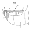
- FIGS. 3 and 4 are enlarged end views (partial sectional views) showing the lower portion of the C-shaped frame and the die assembly 18.
- the die assembly is in a lifted position.
- the movable table 31 can be rotated in a direction orthogonal to the axis of the punch.
- FIG 4 shows the die assembly 18 in a lowered position. In the lowered position, the movable table 31 is precluded from rotational movement, and the rivet is fastened while the die assembly is in the lowered position.
- FIG. 3 shows the state after the die assembly 18 having the dies 26, 27, 28, 29, 30 mounted on the movable table 31 is rotated to allow one selected die 26 to be located below the punch (not shown).
- a driving device 32 is provided in the C-shaped frame 11. The driving device 32 is operable to move the shaft 33 vertically (in the axial direction of the punch) for allowing the die assembly 18 to be moved vertically.
- the driving device 32 includes a lifting mechanism for vertically moving the die assembly.
- the lifting mechanism includes an electromagnet, and is operable to magnetize the electromagnet to move the movable table 31 upward to the lifted position. It is also operable to demagnetize the electromagnet for shifting the movable table 31 downward to the lowered position.
- the driving device In the lifted position of the die assembly 18 as shown in FIG. 3, the driving device is allowed to rotate the shaft 33 and the die assembly 18.
- the driving device 32 further includes a servomotor for rotating the die assembly 18.
- the self-piercing rivet setting apparatus also includes an encoder for detecting the rotational position of the die assembly 18.
- the servomotor is adapted to rotate rotatable table 31 while detecting the rotational position of the rotatable table 31 by means of the encoder so as to accurately move the rotatable table to a given rotational position.
- the self-piercing rivet setting apparatus is adapted to automatically select a desired die according to a rivet setting condition achieved, and the relationship between the respective dies and corresponding rivet setting conditions such as the thickness and/or material of workpieces to be fastened is determined in advance.
- an operator may directly introduce information about a desired die to allow the self-piercing rivet setting apparatus to select the desired die.
- the lower portion of the die 26 is formed as a column-like shank 36, and the lower portion of the die 28 is formed as a column-like shank 38.
- the lower portion of other dies is also formed as a column-like shank.
- the shanks 36, 38 have the same shape.
- the lower portion of the C-shaped frame is formed with a die mounting hole 41 for receiving the shank 36, 38 therein.
- the inner diameter of the die mounting hole 41 is set in conformity with the outer diameter of shank 36 so as to allow the die mounting hole 41 to receive and hold the shank 36 at a given rivet setting position.
- the die mounting hole 41 can receive the shank of other die 28 etc. in the same manner.
- FIG. 4 shows the state after the die assembly 18 is moved downward to the lowered position, and the shank 36 of the die is inserted into the die mounting hole 41 formed in the lower portion of the C-shaped frame.
- the bottom surface of the movable table 31 is in contact with the receiving surface 42 around the upper end of the die mounting hole 41. In this state, the die 26 is fixed to the C-shaped frame 11.
- FIG. 5 is an end view (partial sectional view) showing the state after the workpieces 2, 3 are fastened together.
- FIG. 6 is a fragmentary enlarged view of the region fastened by a rivet 1 in FIG. 5.
- the die 26 includes a cavity 25 having a bottom surface formed with a protrusion 43 at the center thereof.
- the leg of the rivet is expanded in a radially outward direction by the protrusion 44.
- the cavity of the die may be formed as an approximately flat surface.
- the shape of the cavity of the die in FIG 6 is simply shown as one example, yet the present invention is not limited to such a shape.
- the punch 14 drives the rivet 1 into the workpieces 2, 3 while clamping the workpieces 2, 3 between the receiver unit 15 and the die 26.
- the leg of the rivet 1 is deformed by the protrusion 43 formed at the center of the cavity 25 while piercing the workpieces 2, 3, to allow the front end of the leg to be expanded in a radially outward direction and to stay in the workpieces without penetrating therethrough.
- the workpieces 2, 3 are fastened by the expanded leg and the head of the rivet 1.
- the driving device 32 rotates the die assembly 18 in the lifted position to allow a desired die 26 to be rotated to the position below the punch 14. Then, the driving device 32 moves the die assembly downward to the lowered position to insert the shank 36 of the die into the die mounting hole 41 so that the die 26 is fixed to the C-shaped frame 11.
- the setting mechanism 13 pushes the punch 14 downward to allow the self-piercing rivet held by the receiver unit 15 located on the lower side of the punch to be driven into the workpieces 2, 3 so as to fasten the workpieces together.
- the movable table in the above embodiment is formed in a disk shape
- the movable table of the present invention is not limited to such a shape.
- the movable table may be formed in a rectangular shape.
- a plurality of dies are mounted on the movable table in a linear line, and the die may be replaced by moving the movable table linearly.
- the rivet setting apparatus comprising the die assembly with the plurality of dies is used to fasten workpieces together by a self-piercing rivet, and the dies can be replaced quickly depending on the setting condition. As a result, enhanced productivity is obtained.
Landscapes
- Engineering & Computer Science (AREA)
- Mechanical Engineering (AREA)
- Insertion Pins And Rivets (AREA)
- Connection Of Plates (AREA)
Abstract
Description
- The present invention relates to a self-piercing rivet setting apparatus using a self-piercing rivet having a large head and a hollow leg extending downward from the head to fasten a plurality of workpieces together, and in particular to a mechanism for changing dies to be used in the above apparatus.
- In order to comply with the demand for weight reduction in transport apparatuses or the like, aluminum alloy components have been increasingly employed therein in former times. Generally, a welding process is not suitable for aluminum panels of automobiles or the like, and such panels are typically fastened together using a self-piercing rivet.
- Particularly in a body assembling operation for automobiles or the like (more particularly in an assembling operation of an aluminum body), a self-piercing rivet is used to fasten two or more sheet members (or a sheet member and another component) together.
- One example of a self-piercing rivet setting apparatus is disclosed in Japanese Patent Laid-Open Publication No. H 08-505087. A self-piercing rivet comprises a large diameter head (hereinafter, "large head") and a hollow leg extending downward from the head. When the self-piercing rivet is driven into a pair of workpieces, the front end of the leg is expandingly deformed while piercing the workpieces, and the workpieces are finally fastened together by the deformed leg and the large head.
- The self-piercing rivet is driven into workpieces to penetrate through a punch-side workpiece but stay in a receiving-side workpiece adjacent to a die without penetrating therethrough. Thus, after the rivet setting operation, no opening is formed in the surface of the receiving-side workpiece, which provides an advantage of preventing deterioration in a sealing performance of the receiving-side workpiece while maintaining good appearance thereof.
- Fig. 1 is a sectional view showing a connected region of a pair of workpieces fastened by a conventional self-piercing rivet. The self-piercing rivet comprises a
large head 5 and ahollow leg 6 extending downward from the head. The self-piercing rivet is driven into a pair ofworkpieces leg 6 is deformed to allow the front end thereof to be expanded while piercing the workpieces (body panels or the like). As a result, the punch-side workpiece 2 and the receiving-side workpiece 3 are fastened together by thedeformed leg 6 and thelarge head 5. - More specifically, the pair of
workpieces undercut 7 formed by theleg 6 of the rivet expanded in the lateral direction of the receiving-side workpiece 3 (or the radially outward direction of the rivet). - The size or dimension of the rivet should vary depending on the thickness and/or material of a workpiece to be fastened. A die to be used in a rivet setting operation for fastening workpieces should also be changed depending on the thickness and/or material of the workpiece and/or the dimension of the rivet. In case a different die is used, the rivet setting condition for obtaining an optimal undercut will be changed.
- Heretofore, in a rivet setting operation for a different workpiece, a rivet setting apparatus has been changed to another rivet setting apparatus having a different die mounted thereon, or one rivet setting apparatus has been used by substituting one die with another suitable die.
- As regards the approach of using different rivet setting apparatuses, it is required to prepare a plurality of rivet setting apparatus suitable for different rivet setting conditions and to transfer workpieces to the respective locations of these apparatuses. As a result, the use of a plurality of rivet setting apparatuses leads to increased equipment cost, expanded installation space and extended time for a rivet setting operation.
- As regards the approach of die substitution, it is required to change dies in the apparatus frequently, which increases the time needed in operation.
- In view of the above problems, it is an object of the present invention to provide a rivet setting apparatus capable of automatically changing a die for rivet setting operation, thereby enhancing productivity in an assembling line for automobile bodies or the like.
- The present invention is directed to a die for use in a self-piercing rivet setting apparatus. This self-piercing rivet setting apparatus includes a punch and a die for cooperatively driving a self-piercing rivet having a large head and a hollow leg extending downward from the head into a plurality of workpieces. The self-piercing rivet is driven into the workpieces in such a manner that the leg is deformed to allow the front end thereof to be expanded in a radially outward direction while piercing the workpieces and to stay in the workpieces without penetrating therethrough, so as to fasten the plurality of workpieces together by the expanded leg and the head.
- The above self-piercing rivet setting apparatus comprises a die assembly including a movable table and a plurality of dies, and a driving device for moving the die assembly in a direction orthogonal to the axis of the punch and in the axial direction of the punch.
- The driving device is operable to move the die assembly in the direction orthogonal to the axis of the punch to allow one of the plurality of dies to be moved to a position located axially below the punch.
- The driving device is operable to move the die assembly in the axial direction of the punch and in the range between a lifted position and a lowered position of the die assembly.
- In the lifted position, the driving device is allowed to move the die assembly in the direction orthogonal to the axis of the punch.
In the lowered position, the driving device is prevented from moving the die assembly in the direction orthogonal to the axis of the punch, so that the selected die is fixed in a die mounting hole located below the punch. - In the lowered position of the die assembly, the punch is operable to drive the rivet into the workpieces and fasten them together.
- The die assembly may include three or more dies.
- The movable table may have a disk shape. In this case, the plurality of dies may be mounted on the periphery of the movable table, and the driving device may be operable to rotate the die assembly so as to move the dies in the direction orthogonal to the axis of the punch. The driving device may include a rotary motor.
- The plurality of dies may be mounted on the movable table in a linear line. In this case, the driving device may be operable to linearly move the die assembly so as to displace the dies in the direction orthogonal to the axis of the punch. The driving device may include a linear motor.
- The self-piercing rivet setting apparatus may be adapted to select one of the dies to be used from the plurality of dies according to a rivet setting condition achieved.
- The self-piercing rivet setting apparatus may include a sensor for detecting the position of the movable table, wherein the driving device is controllably operated on command of a positional signal from the sensor.
- An embodiment of the present invention will now be described making reference to the accompanying drawings, wherein:
- FIG. 1 is a sectional view showing the state after a self-piercing rivet is driven into workpieces by a rivet setting apparatus.
- FIG 2 is a perspective view of a self-piercing rivet setting apparatus according to one embodiment of the present invention.
- FIG 3 is an enlarged end view (partial sectional view) showing a C-shaped frame and a die assembly in its lifted position.
- FIG 4 is an enlarged end view (partial sectional view) showing the C-shaped frame and the die assembly in its lowered position.
- FIG. 5 is an end view (partial sectional view) showing the state after workpieces are fastened together by a rivet.
-
- FIG. 5 is an enlarged view of the region fastened by the rivet in FIG 5.
- FIG. 2 is a schematic general diagram of a self-piercing rivet setting apparatus according to one embodiment of the present invention. In FIG. 2, the self-piercing rivet setting apparatus includes a C-
shaped frame 11. The C-shaped frame 11 has an upper horizontal arm portion, a lower horizontal portion, and a vertical arm portion connecting the upper and lower horizontal portions, wherein the respective portions are integrally formed. The C-shaped frame 11 can be elastically deformed to absorb shocks during a rivet setting operation. The vertical arm portion of the C-shaped frame 11 includes acoupling region 10 to be coupled with an articulated robot arm (not shown). - A
setting mechanism 13 of the self-piercing rivet setting apparatus is attached to one end of the upper horizontal arm portion. Apunch 14 is attached to the lower portion of thesetting mechanism 13, the punch being movable verticallyA receiver unit 15 for holding a self-piercing rivet is provided at the lower side of thepunch 14. - A
spindle driving unit 17 is provided on the upper side of thepunch 14. Thespindle driving unit 17 comprises anelectric driving motor 19, areduction gear mechanism 21 for transmitting a rotational force of the motor, agear mechanism 22, and aspindle 23 which is driven by the gear mechanism and adapted to move vertically while rotating. Thesetting mechanism 13 is adapted to push thepunch 14 downward to allow the self-piercing rivet held by thereceiver unit 15 located on the lower side of the punch to be driven into workpieces held on adie assembly 18. - The die
assembly 18 is attached at one end of the lower horizontal arm portion of the C-shaped frame 11. In a specific embodiment of the present invention, the dieassembly 18 includes a movable table 31, a plurality of dies on the movable table 31, and ashaft 33 attached at the center of the movable table. The movable table 31 is formed as a disk-shaped flat plate, and is controllably rotated around the center shaft. In the embodiment illustrated in FIG. 2, fivedies dies punch 14. - Upon activation of the
electric driving motor 19, thespindle 23 is vertically moved, and thepunch 14 is moved by the spindle to push a self-piercing rivet held by thereceiver unit 15 toward thedie 26. A plurality of workpieces (e.g. theworkpiece die assembly 18. As thepunch 14 is lowered, the self-piercing rivet gradually pierces the workpiece. As a result, the plurality of workpieces will be fastened together. - FIGS. 3 and 4 are enlarged end views (partial sectional views) showing the lower portion of the C-shaped frame and the
die assembly 18. In FIG. 3, the die assembly is in a lifted position. In the lifted position, the movable table 31 can be rotated in a direction orthogonal to the axis of the punch. FIG 4 shows thedie assembly 18 in a lowered position. In the lowered position, the movable table 31 is precluded from rotational movement, and the rivet is fastened while the die assembly is in the lowered position. - FIG. 3 shows the state after the
die assembly 18 having the dies 26, 27, 28, 29, 30 mounted on the movable table 31 is rotated to allow one selected die 26 to be located below the punch (not shown). A drivingdevice 32 is provided in the C-shapedframe 11. The drivingdevice 32 is operable to move theshaft 33 vertically (in the axial direction of the punch) for allowing thedie assembly 18 to be moved vertically. The drivingdevice 32 includes a lifting mechanism for vertically moving the die assembly. The lifting mechanism includes an electromagnet, and is operable to magnetize the electromagnet to move the movable table 31 upward to the lifted position. It is also operable to demagnetize the electromagnet for shifting the movable table 31 downward to the lowered position. - In the lifted position of the
die assembly 18 as shown in FIG. 3, the driving device is allowed to rotate theshaft 33 and thedie assembly 18. The drivingdevice 32 further includes a servomotor for rotating thedie assembly 18. The self-piercing rivet setting apparatus also includes an encoder for detecting the rotational position of thedie assembly 18. The servomotor is adapted to rotate rotatable table 31 while detecting the rotational position of the rotatable table 31 by means of the encoder so as to accurately move the rotatable table to a given rotational position. - In a specific embodiment of the present invention, the self-piercing rivet setting apparatus is adapted to automatically select a desired die according to a rivet setting condition achieved, and the relationship between the respective dies and corresponding rivet setting conditions such as the thickness and/or material of workpieces to be fastened is determined in advance.
- Alternatively, an operator may directly introduce information about a desired die to allow the self-piercing rivet setting apparatus to select the desired die.
- The lower portion of the die 26 is formed as a column-
like shank 36, and the lower portion of the die 28 is formed as a column-like shank 38. The lower portion of other dies is also formed as a column-like shank. Theshanks die mounting hole 41 for receiving theshank die mounting hole 41 is set in conformity with the outer diameter ofshank 36 so as to allow thedie mounting hole 41 to receive and hold theshank 36 at a given rivet setting position. Thedie mounting hole 41 can receive the shank of other die 28 etc. in the same manner. - FIG. 4 shows the state after the
die assembly 18 is moved downward to the lowered position, and theshank 36 of the die is inserted into thedie mounting hole 41 formed in the lower portion of the C-shaped frame. The bottom surface of the movable table 31 is in contact with the receivingsurface 42 around the upper end of thedie mounting hole 41. In this state, thedie 26 is fixed to the C-shapedframe 11. - FIG. 5 is an end view (partial sectional view) showing the state after the
workpieces rivet 1 in FIG. 5. - The
die 26 includes acavity 25 having a bottom surface formed with aprotrusion 43 at the center thereof. The leg of the rivet is expanded in a radially outward direction by the protrusion 44. The cavity of the die may be formed as an approximately flat surface. The shape of the cavity of the die in FIG 6 is simply shown as one example, yet the present invention is not limited to such a shape. - The
punch 14 drives therivet 1 into theworkpieces workpieces receiver unit 15 and thedie 26. The leg of therivet 1 is deformed by theprotrusion 43 formed at the center of thecavity 25 while piercing theworkpieces workpieces rivet 1. - In advance of the rivet setting operation, the driving
device 32 rotates thedie assembly 18 in the lifted position to allow a desireddie 26 to be rotated to the position below thepunch 14. Then, the drivingdevice 32 moves the die assembly downward to the lowered position to insert theshank 36 of the die into thedie mounting hole 41 so that thedie 26 is fixed to the C-shapedframe 11. - The
setting mechanism 13 pushes thepunch 14 downward to allow the self-piercing rivet held by thereceiver unit 15 located on the lower side of the punch to be driven into theworkpieces - While the movable table in the above embodiment is formed in a disk shape, the movable table of the present invention is not limited to such a shape. For example, the movable table may be formed in a rectangular shape. In this case, a plurality of dies are mounted on the movable table in a linear line, and the die may be replaced by moving the movable table linearly.
- As mentioned above, according to the present invention, the rivet setting apparatus comprising the die assembly with the plurality of dies is used to fasten workpieces together by a self-piercing rivet, and the dies can be replaced quickly depending on the setting condition. As a result, enhanced productivity is obtained.
-
- 1:
- self-piercing rivet
- 2, 3:
- workpiece
- 5:
- head
- 6:
- leg
- 7:
- undercut amount
- 9:
- rivet setting apparatus
- 10:
- coupling region to robot arm
- 11:
- C-shaped frame
- 13:
- setting mechanism
- 14:
- punch
- 15:
- receiver unit
- 17:
- spindle driving unit
- 18:
- die assembly
- 19:
- motor
- 21:
- reduction gear mechanism
- 22:
- gear mechanism
- 23:
- spindle
- 26,27, 27, 28, 29, 30:
- die
- 31:
- movable table
- 32:
- driving device
- 33:
- shaft
- 36,
- 28: shank
- 41:
- die mounting hole
- 42:
- receiving surface
- 43:
- protrusion
Claims (8)
- A self-piercing rivet setting apparatus including a punch and a die for cooperatively driving a self-piercing rivet having a large head and a hollow leg extending downward from said head into a plurality of workpieces,
wherein said self-piercing rivet is driven into said workpieces in such a manner that said leg is deformed to allow the front end thereof to be expanded radially outward while piercing said workpieces and to stay in said workpieces without penetrating therethrough, so as to fasten said plurality of workpieces together by said expanded leg and said head,
said self-piercing rivet setting apparatus comprising:a die assembly including a movable table and a plurality of dies; anda driving device for moving said die assembly in a direction orthogonal to the axis of said punch and in the axial direction of said punch, whereinsaid driving device is operable to move said die assembly in the direction orthogonal to the axis of said punch to allow one of said plurality of dies to be moved to a position located axially below said punch, andsaid driving device is operable to move said die assembly in the axial direction of said punch and in the range between a lifted position and a lowered position of said die assembly, whereinin said lifted position, said driving device is allowed to move said die assembly in the direction orthogonal to the axis of said punch, andin said lowered position, said driving device is prevented from moving said die assembly in the direction orthogonal to the axis of said punch, so that said selected die is fixed in a die mounting hole located below said punch. - The self-piercing rivet setting apparatus as defined in claim 1, wherein said die assembly includes three or more dies.
- The self-piercing rivet setting apparatus as defined in claim 1, wherein said movable table has a disk shape, wherein said plurality of dies are mounted on the periphery of said movable table, and said driving device is operable to rotate said die assembly so as to move said dies in the direction orthogonal to the axis of said punch.
- The self-piercing rivet setting apparatus as defined in claim 3, wherein said driving device includes a rotary motor.
- The self-piercing rivet setting apparatus as defined in claim 1, wherein said plurality of dies are mounted on said movable table in a linear line, wherein said driving device is operable to linearly move said die assembly so as to displace said dies in the direction orthogonal to the axis of said punch.
- The self-piercing rivet setting apparatus as defined in claim 5, wherein said driving device includes a linear motor.
- The self-piercing rivet setting apparatus as defined in claim 1, which is adapted to select one die to be used from said plurality of dies according to a rivet setting condition achieved.
- The self-piercing rivet setting apparatus as defined in claim 1, which includes a sensor for detecting the position of said movable table, wherein said driving device is controllably operated on command of a positional signal from said sensor.
Applications Claiming Priority (2)
| Application Number | Priority Date | Filing Date | Title |
|---|---|---|---|
| JP2002160054A JP2004001045A (en) | 2002-05-31 | 2002-05-31 | Apparatus for automatically drilling and riveting |
| JP2002160054 | 2002-05-31 |
Publications (2)
| Publication Number | Publication Date |
|---|---|
| EP1366836A1 true EP1366836A1 (en) | 2003-12-03 |
| EP1366836B1 EP1366836B1 (en) | 2005-07-27 |
Family
ID=29417268
Family Applications (1)
| Application Number | Title | Priority Date | Filing Date |
|---|---|---|---|
| EP03010633A Expired - Lifetime EP1366836B1 (en) | 2002-05-31 | 2003-05-13 | Self-piercing rivet setting apparatus |
Country Status (6)
| Country | Link |
|---|---|
| US (1) | US6964094B2 (en) |
| EP (1) | EP1366836B1 (en) |
| JP (1) | JP2004001045A (en) |
| KR (1) | KR20030093954A (en) |
| DE (1) | DE60301090T2 (en) |
| ES (1) | ES2246440T3 (en) |
Cited By (11)
| Publication number | Priority date | Publication date | Assignee | Title |
|---|---|---|---|---|
| CN1873824B (en) * | 2006-03-14 | 2010-05-26 | 深圳易拓科技有限公司 | Equipment for automatic riveting butted seal ring and separability type hard disk drive |
| CN103231250A (en) * | 2013-05-03 | 2013-08-07 | 西北工业大学 | Multi-functional drilling-riveting actuator |
| WO2015161999A1 (en) * | 2014-04-25 | 2015-10-29 | Bayerische Motoren Werke Aktiengesellschaft | Method for the series production of punch rivet connections between frp workpieces and metal workpieces |
| CN106378409A (en) * | 2016-11-16 | 2017-02-08 | 浙江大学 | Pier head height control method for automatic drilling and riveting machine |
| WO2018229502A1 (en) * | 2017-06-16 | 2018-12-20 | Henrob Limited | Die changing apparatus |
| CN111376032A (en) * | 2018-12-28 | 2020-07-07 | 利星行能源(昆山)有限公司 | Moving tool and moving method of generator |
| CN112620569A (en) * | 2021-01-13 | 2021-04-09 | 苏州艾锐珐金属制品有限公司 | Automatic press riveting equipment and press riveting method thereof |
| US20210207638A1 (en) * | 2018-09-21 | 2021-07-08 | Newfrey Llc | Self-piercing rivet |
| CN114472727A (en) * | 2020-10-28 | 2022-05-13 | 富准精密模具(嘉善)有限公司 | Riveting device |
| DE102020134085A1 (en) | 2020-12-18 | 2022-06-23 | Audi Aktiengesellschaft | Die changer for stationary punch riveting systems |
| CN115870399A (en) * | 2022-12-13 | 2023-03-31 | 苏州童蒙养正精密制造科技有限公司 | Die casting accurate positioning automatic punching equipment |
Families Citing this family (33)
| Publication number | Priority date | Publication date | Assignee | Title |
|---|---|---|---|---|
| EP1366304A2 (en) * | 2001-03-09 | 2003-12-03 | Newfrey LLC | Self-punching rivet, method and device for setting a rivet element and the use thereof |
| US20060251495A1 (en) * | 2001-03-09 | 2006-11-09 | Reinhold Opper | Self-piercing rivet, process and device for setting a rivet element, and employment thereof |
| JP2004358523A (en) * | 2003-06-05 | 2004-12-24 | Nippon Pop Rivets & Fasteners Ltd | Device for repairing fastened self-piercing type rivet, removing it, and fastening solid rivet |
| US7305755B2 (en) * | 2003-12-18 | 2007-12-11 | Heiko Schmidt | Processing tong |
| DE102004005884B4 (en) | 2004-02-05 | 2012-03-29 | Newfrey Llc | Joining device with a punch tool and a counter tool and a holder |
| US8196794B2 (en) * | 2004-08-24 | 2012-06-12 | Ford Motor Company | Riveting system and multi-piece self pierce die for improved die life |
| SE530342C2 (en) * | 2005-11-24 | 2008-05-06 | Pressmaster Ab | Crimping Tools |
| US8549723B2 (en) * | 2007-05-11 | 2013-10-08 | The Boeing Company | Method and apparatus for squeezing parts such as fasteners |
| USD599383S1 (en) * | 2009-04-08 | 2009-09-01 | Chia-Lin Tsai | Riveting machine |
| USD599382S1 (en) * | 2009-04-08 | 2009-09-01 | Chia-Lin Tsai | Riveting machine |
| US8402633B2 (en) * | 2010-06-11 | 2013-03-26 | GM Global Technology Operations LLC | Method for repairing self-piercing riveted workpieces |
| USD632318S1 (en) * | 2010-09-23 | 2011-02-08 | Weaver Leather, Llc | Bench riveter |
| DE202010014665U1 (en) | 2010-10-25 | 2011-01-13 | Eckold Gmbh & Co. Kg | Rotary drive and device for joining with rotary drive |
| EP2637812B1 (en) * | 2010-11-10 | 2018-02-21 | Henrob Limited | Riveting method |
| USD662528S1 (en) * | 2012-02-16 | 2012-06-26 | Brown Michael C | Eyelet setting die set |
| USD663330S1 (en) * | 2012-02-16 | 2012-07-10 | Brown Michael C | Eyelet removal die set |
| USD664573S1 (en) * | 2012-02-16 | 2012-07-31 | Brown Michael C | Rivet removal tool set |
| USD668279S1 (en) * | 2012-06-22 | 2012-10-02 | Brown Michael C | Rivet removal tool set |
| US9162277B2 (en) | 2013-02-18 | 2015-10-20 | Ford Motor Company | Indexing self-piercing die riveter |
| US9718157B2 (en) * | 2014-02-21 | 2017-08-01 | Ford Global Technologies, Llc | Expanding die for clinching and riveting operations |
| KR101649889B1 (en) * | 2014-12-12 | 2016-08-23 | 주식회사 성우하이텍 | Frame for self-piercing rivet system |
| KR101696364B1 (en) * | 2015-08-21 | 2017-01-13 | 이순녀 | Riveting machine |
| CN105499467B (en) * | 2015-12-15 | 2018-08-10 | 新沂市港发商贸有限公司 | Riveter for stepped locations riveting |
| CN106734832B (en) * | 2016-11-16 | 2018-05-22 | 浙江大学 | A kind of automatic drill riveter presses power displacement mixing control method |
| GB2563450B (en) * | 2017-06-16 | 2022-03-23 | Atlas Copco Ias Uk Ltd | Cartridge |
| GB2569127A (en) | 2017-12-05 | 2019-06-12 | Atlas Copco Ias Uk Ltd | Nose arrangements for fastener setting machines, and related methods |
| GB2569122A (en) | 2017-12-05 | 2019-06-12 | Atlas Copco Ias Uk Ltd | Fastener handling devices for fastener setting machines, and related methods |
| GB2569126A (en) | 2017-12-05 | 2019-06-12 | Atlas Copco Ias Uk Ltd | Fastener magazines, and related supply systems and methods |
| US10898943B2 (en) * | 2018-09-25 | 2021-01-26 | Ford Global Technologies, Llc | Self-piercing rivet device and method of operating a self-piercing rivet device to inhibit incorrect die usage |
| JP7182989B2 (en) * | 2018-10-12 | 2022-12-05 | 株式会社アーレスティ | Joined product manufacturing method and plate member quality control method |
| CN114147444B (en) * | 2021-12-01 | 2023-01-17 | 广东恒力精密工业有限公司 | Assembling machine for automobile seat sliding rod assembly |
| KR102766015B1 (en) * | 2022-05-11 | 2025-02-13 | (주)현대하이텍 | Mold for in-die riveting and method for manufacturing part using the same |
| KR102789775B1 (en) * | 2022-05-26 | 2025-03-31 | 서울과학기술대학교 산학협력단 | Compound forming method and apparatus capable of using electromagnetic forming and incremental forming |
Citations (4)
| Publication number | Priority date | Publication date | Assignee | Title |
|---|---|---|---|---|
| FR891986A (en) * | 1942-03-26 | 1944-03-24 | Arado Flugzeugwerke Gmbh | Riveting machine comprising several lower tool holders |
| GB834066A (en) * | 1957-08-07 | 1960-05-04 | Garrard Eng & Mfg Co Ltd | Improvements in or relating to riveting machines or the like |
| JPH08505087A (en) * | 1992-12-19 | 1996-06-04 | ヘンロブ・リミテッド | Improvement of self-piercing rivets |
| EP0983810A2 (en) * | 1998-09-04 | 2000-03-08 | Haeger, Inc. | Automatic tool changing machine |
Family Cites Families (21)
| Publication number | Priority date | Publication date | Assignee | Title |
|---|---|---|---|---|
| US29450A (en) * | 1860-08-07 | Knitting-machine | ||
| US46804A (en) * | 1865-03-14 | Method of preparing colors from autilin | ||
| US533195A (en) * | 1895-01-29 | Dentist s grown swaging apparatus | ||
| US141102A (en) * | 1873-07-22 | Improvement in compound faucets | ||
| US1203124A (en) * | 1914-11-13 | 1916-10-31 | William T Lyon | Thimble-swaging apparatus. |
| US1850671A (en) * | 1931-04-06 | 1932-03-22 | Judson L Thomson Mfg Co | Duplex riveting machine with anvil turntable |
| US2257379A (en) * | 1939-05-10 | 1941-09-30 | Judson L Thomson Mfg Company | Work support for riveting and similar machines |
| US3611773A (en) * | 1970-02-16 | 1971-10-12 | Waterloo Spring Co Ltd | Turret anvil riveting machine |
| US4047281A (en) * | 1975-05-28 | 1977-09-13 | Marson Corporation | Method of setting blind rivets |
| US4312107A (en) * | 1979-12-26 | 1982-01-26 | The Milford Rivet & Machine Co. | Automatic arcuate brake shoe riveting machine and method |
| US5218756A (en) * | 1992-03-23 | 1993-06-15 | Pylon Tool Corporation | Modular punch press station |
| DE4320068C1 (en) * | 1993-06-17 | 1994-12-15 | Audi Ag | Method and device for repairing vehicle bodies made of light metal parts |
| US6240332B1 (en) * | 1994-04-29 | 2001-05-29 | The Boeing Company | Tooling head controller |
| US5615474A (en) * | 1994-09-09 | 1997-04-01 | Gemcor Engineering Corp. | Automatic fastening machine with statistical process control |
| WO2000015373A1 (en) | 1998-09-11 | 2000-03-23 | General Electro Mechanical Corporation | Rotary turret head apparatus |
| US6161279A (en) * | 1999-06-18 | 2000-12-19 | Suboski; Alan L. | Pierce nut mounting die |
| US6789309B2 (en) | 2000-02-22 | 2004-09-14 | Newfrey Llc | Self-piercing robotic rivet setting system |
| JP2001353549A (en) | 2000-06-14 | 2001-12-25 | Nippon Pop Rivets & Fasteners Ltd | Automatic drilling type riveting machine |
| US6546613B2 (en) | 2001-08-29 | 2003-04-15 | Textron Inc. | Anvil design for rivet setting machine |
| US6910263B2 (en) * | 2001-12-25 | 2005-06-28 | Newfrey Llc | Self-piercing rivet setting apparatus and system |
| JP2004358523A (en) * | 2003-06-05 | 2004-12-24 | Nippon Pop Rivets & Fasteners Ltd | Device for repairing fastened self-piercing type rivet, removing it, and fastening solid rivet |
-
2002
- 2002-05-31 JP JP2002160054A patent/JP2004001045A/en active Pending
-
2003
- 2003-05-13 ES ES03010633T patent/ES2246440T3/en not_active Expired - Lifetime
- 2003-05-13 EP EP03010633A patent/EP1366836B1/en not_active Expired - Lifetime
- 2003-05-13 DE DE60301090T patent/DE60301090T2/en not_active Expired - Fee Related
- 2003-05-14 KR KR10-2003-0030560A patent/KR20030093954A/en not_active Abandoned
- 2003-05-28 US US10/445,892 patent/US6964094B2/en not_active Expired - Fee Related
Patent Citations (5)
| Publication number | Priority date | Publication date | Assignee | Title |
|---|---|---|---|---|
| FR891986A (en) * | 1942-03-26 | 1944-03-24 | Arado Flugzeugwerke Gmbh | Riveting machine comprising several lower tool holders |
| GB834066A (en) * | 1957-08-07 | 1960-05-04 | Garrard Eng & Mfg Co Ltd | Improvements in or relating to riveting machines or the like |
| JPH08505087A (en) * | 1992-12-19 | 1996-06-04 | ヘンロブ・リミテッド | Improvement of self-piercing rivets |
| US5752305A (en) * | 1992-12-19 | 1998-05-19 | Henrob Limited | Self-piercing riveting method and apparatus |
| EP0983810A2 (en) * | 1998-09-04 | 2000-03-08 | Haeger, Inc. | Automatic tool changing machine |
Non-Patent Citations (1)
| Title |
|---|
| PATENT ABSTRACTS OF JAPAN * |
Cited By (15)
| Publication number | Priority date | Publication date | Assignee | Title |
|---|---|---|---|---|
| CN1873824B (en) * | 2006-03-14 | 2010-05-26 | 深圳易拓科技有限公司 | Equipment for automatic riveting butted seal ring and separability type hard disk drive |
| CN103231250A (en) * | 2013-05-03 | 2013-08-07 | 西北工业大学 | Multi-functional drilling-riveting actuator |
| CN103231250B (en) * | 2013-05-03 | 2015-08-12 | 西北工业大学 | A kind of multi-functional drill riveting actuator |
| CN105916611B (en) * | 2014-04-25 | 2018-02-23 | 宝马股份公司 | Method for establishing punch riveting connection in batches between FVK workpiece and metal works |
| CN105916611A (en) * | 2014-04-25 | 2016-08-31 | 宝马股份公司 | Method for the series production of punch rivet connections between FVK workpieces and metal workpieces |
| WO2015161999A1 (en) * | 2014-04-25 | 2015-10-29 | Bayerische Motoren Werke Aktiengesellschaft | Method for the series production of punch rivet connections between frp workpieces and metal workpieces |
| CN106378409A (en) * | 2016-11-16 | 2017-02-08 | 浙江大学 | Pier head height control method for automatic drilling and riveting machine |
| WO2018229502A1 (en) * | 2017-06-16 | 2018-12-20 | Henrob Limited | Die changing apparatus |
| US11524329B2 (en) | 2017-06-16 | 2022-12-13 | Atlas Copco Ias Uk Limited | Die changing apparatus |
| US20210207638A1 (en) * | 2018-09-21 | 2021-07-08 | Newfrey Llc | Self-piercing rivet |
| CN111376032A (en) * | 2018-12-28 | 2020-07-07 | 利星行能源(昆山)有限公司 | Moving tool and moving method of generator |
| CN114472727A (en) * | 2020-10-28 | 2022-05-13 | 富准精密模具(嘉善)有限公司 | Riveting device |
| DE102020134085A1 (en) | 2020-12-18 | 2022-06-23 | Audi Aktiengesellschaft | Die changer for stationary punch riveting systems |
| CN112620569A (en) * | 2021-01-13 | 2021-04-09 | 苏州艾锐珐金属制品有限公司 | Automatic press riveting equipment and press riveting method thereof |
| CN115870399A (en) * | 2022-12-13 | 2023-03-31 | 苏州童蒙养正精密制造科技有限公司 | Die casting accurate positioning automatic punching equipment |
Also Published As
| Publication number | Publication date |
|---|---|
| DE60301090D1 (en) | 2005-09-01 |
| KR20030093954A (en) | 2003-12-11 |
| DE60301090T2 (en) | 2006-04-20 |
| ES2246440T3 (en) | 2006-02-16 |
| EP1366836B1 (en) | 2005-07-27 |
| US6964094B2 (en) | 2005-11-15 |
| US20040060958A1 (en) | 2004-04-01 |
| JP2004001045A (en) | 2004-01-08 |
Similar Documents
| Publication | Publication Date | Title |
|---|---|---|
| EP1366836B1 (en) | Self-piercing rivet setting apparatus | |
| US6910263B2 (en) | Self-piercing rivet setting apparatus and system | |
| EP1069961B1 (en) | Self-extruded bushing assembly and method of making the same | |
| US5062337A (en) | Indexable multi-tool for punch press | |
| US20050178816A1 (en) | Friction stir rivet drive system and stir riveting methods | |
| US20040111878A1 (en) | Self-piercing rivet setting machine | |
| EP1163963B1 (en) | Rivet setting machine | |
| US4884431A (en) | Apparatus for body panel attachment | |
| JPS62142035A (en) | Molding method and device | |
| EP1745871B1 (en) | Improved automatic riveting system | |
| EP1480782B1 (en) | Process for setting self-piercing rivets | |
| JP2008302399A (en) | Striking device | |
| JPH07132327A (en) | Roller hemming device | |
| JP3096404B2 (en) | Robot hand device | |
| WO2002083337A1 (en) | Self-piercing rivet setting machine | |
| CA2469651A1 (en) | Self-piercing rivet setting apparatus and system | |
| US12502702B2 (en) | Press brake with rotary tool assembly | |
| US20030051332A1 (en) | Method and apparatus for connecting two or more components by soldering | |
| CN218426534U (en) | Automatic quick-change welding device of robot | |
| JP4853184B2 (en) | Friction spot welding device | |
| CN222113250U (en) | Pushing machine table of hydraulic rod | |
| CN220259284U (en) | Tooling device for steel pipe punching | |
| CN112453195A (en) | Gasket machining equipment and machining method thereof | |
| JP2001269725A (en) | Punch press | |
| WO2003064105A1 (en) | Self-piercing rivet setting apparatus |
Legal Events
| Date | Code | Title | Description |
|---|---|---|---|
| PUAI | Public reference made under article 153(3) epc to a published international application that has entered the european phase |
Free format text: ORIGINAL CODE: 0009012 |
|
| AK | Designated contracting states |
Kind code of ref document: A1 Designated state(s): AT BE BG CH CY CZ DE DK EE ES FI FR GB GR HU IE IT LI LU MC NL PT RO SE SI SK TR |
|
| AX | Request for extension of the european patent |
Extension state: AL LT LV MK |
|
| RAP1 | Party data changed (applicant data changed or rights of an application transferred) |
Owner name: NEWFREY LLC |
|
| 17P | Request for examination filed |
Effective date: 20040521 |
|
| AKX | Designation fees paid |
Designated state(s): DE ES FR GB IT |
|
| GRAP | Despatch of communication of intention to grant a patent |
Free format text: ORIGINAL CODE: EPIDOSNIGR1 |
|
| GRAS | Grant fee paid |
Free format text: ORIGINAL CODE: EPIDOSNIGR3 |
|
| GRAA | (expected) grant |
Free format text: ORIGINAL CODE: 0009210 |
|
| AK | Designated contracting states |
Kind code of ref document: B1 Designated state(s): DE ES FR GB IT |
|
| REG | Reference to a national code |
Ref country code: GB Ref legal event code: FG4D |
|
| REF | Corresponds to: |
Ref document number: 60301090 Country of ref document: DE Date of ref document: 20050901 Kind code of ref document: P |
|
| REG | Reference to a national code |
Ref country code: ES Ref legal event code: FG2A Ref document number: 2246440 Country of ref document: ES Kind code of ref document: T3 |
|
| ET | Fr: translation filed | ||
| PLBE | No opposition filed within time limit |
Free format text: ORIGINAL CODE: 0009261 |
|
| STAA | Information on the status of an ep patent application or granted ep patent |
Free format text: STATUS: NO OPPOSITION FILED WITHIN TIME LIMIT |
|
| 26N | No opposition filed |
Effective date: 20060428 |
|
| PGFP | Annual fee paid to national office [announced via postgrant information from national office to epo] |
Ref country code: FR Payment date: 20090518 Year of fee payment: 7 Ref country code: IT Payment date: 20090526 Year of fee payment: 7 |
|
| PGFP | Annual fee paid to national office [announced via postgrant information from national office to epo] |
Ref country code: ES Payment date: 20090526 Year of fee payment: 7 |
|
| PGFP | Annual fee paid to national office [announced via postgrant information from national office to epo] |
Ref country code: DE Payment date: 20090528 Year of fee payment: 7 Ref country code: GB Payment date: 20090528 Year of fee payment: 7 |
|
| GBPC | Gb: european patent ceased through non-payment of renewal fee |
Effective date: 20100513 |
|
| REG | Reference to a national code |
Ref country code: FR Ref legal event code: ST Effective date: 20110131 |
|
| PG25 | Lapsed in a contracting state [announced via postgrant information from national office to epo] |
Ref country code: IT Free format text: LAPSE BECAUSE OF NON-PAYMENT OF DUE FEES Effective date: 20100513 |
|
| PG25 | Lapsed in a contracting state [announced via postgrant information from national office to epo] |
Ref country code: DE Free format text: LAPSE BECAUSE OF NON-PAYMENT OF DUE FEES Effective date: 20101201 |
|
| PG25 | Lapsed in a contracting state [announced via postgrant information from national office to epo] |
Ref country code: FR Free format text: LAPSE BECAUSE OF NON-PAYMENT OF DUE FEES Effective date: 20100531 |
|
| REG | Reference to a national code |
Ref country code: ES Ref legal event code: FD2A Effective date: 20110712 |
|
| PG25 | Lapsed in a contracting state [announced via postgrant information from national office to epo] |
Ref country code: GB Free format text: LAPSE BECAUSE OF NON-PAYMENT OF DUE FEES Effective date: 20100513 Ref country code: ES Free format text: LAPSE BECAUSE OF NON-PAYMENT OF DUE FEES Effective date: 20110630 |
|
| PG25 | Lapsed in a contracting state [announced via postgrant information from national office to epo] |
Ref country code: ES Free format text: LAPSE BECAUSE OF NON-PAYMENT OF DUE FEES Effective date: 20100514 |