EP1366532B1 - Continuous extruded lead alloy strip for battery electrodes - Google Patents
Continuous extruded lead alloy strip for battery electrodes Download PDFInfo
- Publication number
- EP1366532B1 EP1366532B1 EP02701126A EP02701126A EP1366532B1 EP 1366532 B1 EP1366532 B1 EP 1366532B1 EP 02701126 A EP02701126 A EP 02701126A EP 02701126 A EP02701126 A EP 02701126A EP 1366532 B1 EP1366532 B1 EP 1366532B1
- Authority
- EP
- European Patent Office
- Prior art keywords
- strip
- lead alloy
- lead
- alloy
- extrusion
- Prior art date
- Legal status (The legal status is an assumption and is not a legal conclusion. Google has not performed a legal analysis and makes no representation as to the accuracy of the status listed.)
- Expired - Lifetime
Links
- 229910000978 Pb alloy Inorganic materials 0.000 title claims abstract description 52
- 238000000034 method Methods 0.000 claims abstract description 33
- 238000001816 cooling Methods 0.000 claims abstract description 16
- 239000002253 acid Substances 0.000 claims abstract description 12
- 238000001125 extrusion Methods 0.000 claims description 29
- 239000011575 calcium Substances 0.000 claims description 12
- 238000002844 melting Methods 0.000 claims description 11
- 230000008018 melting Effects 0.000 claims description 11
- 229910052791 calcium Inorganic materials 0.000 claims description 10
- OYPRJOBELJOOCE-UHFFFAOYSA-N Calcium Chemical compound [Ca] OYPRJOBELJOOCE-UHFFFAOYSA-N 0.000 claims description 9
- 229910003460 diamond Inorganic materials 0.000 claims description 9
- 239000010432 diamond Substances 0.000 claims description 9
- 238000005520 cutting process Methods 0.000 claims description 6
- 238000010791 quenching Methods 0.000 claims description 6
- 230000000171 quenching effect Effects 0.000 claims description 6
- 238000005096 rolling process Methods 0.000 claims description 5
- 238000010438 heat treatment Methods 0.000 claims description 4
- 238000003698 laser cutting Methods 0.000 claims description 3
- 238000003754 machining Methods 0.000 claims description 3
- 238000004080 punching Methods 0.000 claims description 3
- 229910052709 silver Inorganic materials 0.000 claims description 2
- 238000004804 winding Methods 0.000 claims description 2
- ATJFFYVFTNAWJD-UHFFFAOYSA-N Tin Chemical compound [Sn] ATJFFYVFTNAWJD-UHFFFAOYSA-N 0.000 claims 2
- 239000004332 silver Substances 0.000 claims 1
- 238000004519 manufacturing process Methods 0.000 abstract description 36
- 238000005260 corrosion Methods 0.000 abstract description 16
- 230000007797 corrosion Effects 0.000 abstract description 16
- 230000002829 reductive effect Effects 0.000 abstract description 5
- 229910045601 alloy Inorganic materials 0.000 description 53
- 239000000956 alloy Substances 0.000 description 53
- 238000012360 testing method Methods 0.000 description 17
- 239000000463 material Substances 0.000 description 15
- 230000032683 aging Effects 0.000 description 11
- 230000008569 process Effects 0.000 description 10
- 239000000047 product Substances 0.000 description 10
- 239000000203 mixture Substances 0.000 description 7
- 238000010924 continuous production Methods 0.000 description 6
- 229910052751 metal Inorganic materials 0.000 description 6
- 239000002184 metal Substances 0.000 description 6
- 230000004580 weight loss Effects 0.000 description 6
- 230000007423 decrease Effects 0.000 description 5
- 230000007547 defect Effects 0.000 description 5
- XLYOFNOQVPJJNP-UHFFFAOYSA-N water Substances O XLYOFNOQVPJJNP-UHFFFAOYSA-N 0.000 description 5
- 230000015572 biosynthetic process Effects 0.000 description 3
- 238000009749 continuous casting Methods 0.000 description 3
- 238000013461 design Methods 0.000 description 3
- QAOWNCQODCNURD-UHFFFAOYSA-N Sulfuric acid Chemical compound OS(O)(=O)=O QAOWNCQODCNURD-UHFFFAOYSA-N 0.000 description 2
- 238000007792 addition Methods 0.000 description 2
- 229910052782 aluminium Inorganic materials 0.000 description 2
- 238000005266 casting Methods 0.000 description 2
- 239000011162 core material Substances 0.000 description 2
- 230000003247 decreasing effect Effects 0.000 description 2
- 230000000694 effects Effects 0.000 description 2
- 230000007613 environmental effect Effects 0.000 description 2
- 238000012986 modification Methods 0.000 description 2
- 230000004048 modification Effects 0.000 description 2
- 230000003647 oxidation Effects 0.000 description 2
- 238000007254 oxidation reaction Methods 0.000 description 2
- 239000003507 refrigerant Substances 0.000 description 2
- 239000013535 sea water Substances 0.000 description 2
- 239000007921 spray Substances 0.000 description 2
- 235000011149 sulphuric acid Nutrition 0.000 description 2
- 239000001117 sulphuric acid Substances 0.000 description 2
- 229910052718 tin Inorganic materials 0.000 description 2
- 238000012935 Averaging Methods 0.000 description 1
- 229910000882 Ca alloy Inorganic materials 0.000 description 1
- 229910020220 Pb—Sn Inorganic materials 0.000 description 1
- 229910001245 Sb alloy Inorganic materials 0.000 description 1
- NINIDFKCEFEMDL-UHFFFAOYSA-N Sulfur Chemical compound [S] NINIDFKCEFEMDL-UHFFFAOYSA-N 0.000 description 1
- 239000005864 Sulphur Substances 0.000 description 1
- 238000003483 aging Methods 0.000 description 1
- 238000005275 alloying Methods 0.000 description 1
- XAGFODPZIPBFFR-UHFFFAOYSA-N aluminium Chemical compound [Al] XAGFODPZIPBFFR-UHFFFAOYSA-N 0.000 description 1
- 239000002140 antimony alloy Substances 0.000 description 1
- 230000008901 benefit Effects 0.000 description 1
- 229910002056 binary alloy Inorganic materials 0.000 description 1
- 229910052797 bismuth Inorganic materials 0.000 description 1
- JCXGWMGPZLAOME-UHFFFAOYSA-N bismuth atom Chemical compound [Bi] JCXGWMGPZLAOME-UHFFFAOYSA-N 0.000 description 1
- 238000004140 cleaning Methods 0.000 description 1
- 239000011248 coating agent Substances 0.000 description 1
- 238000000576 coating method Methods 0.000 description 1
- 230000000052 comparative effect Effects 0.000 description 1
- 230000002860 competitive effect Effects 0.000 description 1
- 239000002131 composite material Substances 0.000 description 1
- 238000010276 construction Methods 0.000 description 1
- 238000011109 contamination Methods 0.000 description 1
- 230000001276 controlling effect Effects 0.000 description 1
- 238000007796 conventional method Methods 0.000 description 1
- 239000000498 cooling water Substances 0.000 description 1
- 230000002596 correlated effect Effects 0.000 description 1
- 230000001419 dependent effect Effects 0.000 description 1
- 238000001035 drying Methods 0.000 description 1
- 239000003792 electrolyte Substances 0.000 description 1
- 238000005516 engineering process Methods 0.000 description 1
- 235000012438 extruded product Nutrition 0.000 description 1
- 230000002349 favourable effect Effects 0.000 description 1
- 239000012467 final product Substances 0.000 description 1
- 239000000446 fuel Substances 0.000 description 1
- 230000005484 gravity Effects 0.000 description 1
- 239000012535 impurity Substances 0.000 description 1
- 238000013101 initial test Methods 0.000 description 1
- 230000000670 limiting effect Effects 0.000 description 1
- 239000007788 liquid Substances 0.000 description 1
- 239000011344 liquid material Substances 0.000 description 1
- 238000005461 lubrication Methods 0.000 description 1
- 238000012423 maintenance Methods 0.000 description 1
- QSHDDOUJBYECFT-UHFFFAOYSA-N mercury Chemical compound [Hg] QSHDDOUJBYECFT-UHFFFAOYSA-N 0.000 description 1
- 229910052753 mercury Inorganic materials 0.000 description 1
- 238000005457 optimization Methods 0.000 description 1
- 239000011148 porous material Substances 0.000 description 1
- 238000012545 processing Methods 0.000 description 1
- 230000001681 protective effect Effects 0.000 description 1
- 229910002059 quaternary alloy Inorganic materials 0.000 description 1
- 230000009467 reduction Effects 0.000 description 1
- 230000001105 regulatory effect Effects 0.000 description 1
- 238000005204 segregation Methods 0.000 description 1
- 238000004904 shortening Methods 0.000 description 1
- 229910002058 ternary alloy Inorganic materials 0.000 description 1
- 230000032258 transport Effects 0.000 description 1
- 238000003466 welding Methods 0.000 description 1
Images





Classifications
-
- H—ELECTRICITY
- H01—ELECTRIC ELEMENTS
- H01M—PROCESSES OR MEANS, e.g. BATTERIES, FOR THE DIRECT CONVERSION OF CHEMICAL ENERGY INTO ELECTRICAL ENERGY
- H01M4/00—Electrodes
- H01M4/02—Electrodes composed of, or comprising, active material
- H01M4/14—Electrodes for lead-acid accumulators
- H01M4/16—Processes of manufacture
-
- H—ELECTRICITY
- H01—ELECTRIC ELEMENTS
- H01M—PROCESSES OR MEANS, e.g. BATTERIES, FOR THE DIRECT CONVERSION OF CHEMICAL ENERGY INTO ELECTRICAL ENERGY
- H01M4/00—Electrodes
- H01M4/02—Electrodes composed of, or comprising, active material
- H01M4/64—Carriers or collectors
- H01M4/82—Multi-step processes for manufacturing carriers for lead-acid accumulators
-
- H—ELECTRICITY
- H01—ELECTRIC ELEMENTS
- H01M—PROCESSES OR MEANS, e.g. BATTERIES, FOR THE DIRECT CONVERSION OF CHEMICAL ENERGY INTO ELECTRICAL ENERGY
- H01M4/00—Electrodes
- H01M4/02—Electrodes composed of, or comprising, active material
- H01M4/64—Carriers or collectors
- H01M4/70—Carriers or collectors characterised by shape or form
- H01M4/72—Grids
- H01M4/74—Meshes or woven material; Expanded metal
- H01M4/745—Expanded metal
-
- Y—GENERAL TAGGING OF NEW TECHNOLOGICAL DEVELOPMENTS; GENERAL TAGGING OF CROSS-SECTIONAL TECHNOLOGIES SPANNING OVER SEVERAL SECTIONS OF THE IPC; TECHNICAL SUBJECTS COVERED BY FORMER USPC CROSS-REFERENCE ART COLLECTIONS [XRACs] AND DIGESTS
- Y02—TECHNOLOGIES OR APPLICATIONS FOR MITIGATION OR ADAPTATION AGAINST CLIMATE CHANGE
- Y02E—REDUCTION OF GREENHOUSE GAS [GHG] EMISSIONS, RELATED TO ENERGY GENERATION, TRANSMISSION OR DISTRIBUTION
- Y02E60/00—Enabling technologies; Technologies with a potential or indirect contribution to GHG emissions mitigation
- Y02E60/10—Energy storage using batteries
-
- Y—GENERAL TAGGING OF NEW TECHNOLOGICAL DEVELOPMENTS; GENERAL TAGGING OF CROSS-SECTIONAL TECHNOLOGIES SPANNING OVER SEVERAL SECTIONS OF THE IPC; TECHNICAL SUBJECTS COVERED BY FORMER USPC CROSS-REFERENCE ART COLLECTIONS [XRACs] AND DIGESTS
- Y10—TECHNICAL SUBJECTS COVERED BY FORMER USPC
- Y10T—TECHNICAL SUBJECTS COVERED BY FORMER US CLASSIFICATION
- Y10T29/00—Metal working
- Y10T29/18—Expanded metal making
-
- Y—GENERAL TAGGING OF NEW TECHNOLOGICAL DEVELOPMENTS; GENERAL TAGGING OF CROSS-SECTIONAL TECHNOLOGIES SPANNING OVER SEVERAL SECTIONS OF THE IPC; TECHNICAL SUBJECTS COVERED BY FORMER USPC CROSS-REFERENCE ART COLLECTIONS [XRACs] AND DIGESTS
- Y10—TECHNICAL SUBJECTS COVERED BY FORMER USPC
- Y10T—TECHNICAL SUBJECTS COVERED BY FORMER US CLASSIFICATION
- Y10T428/00—Stock material or miscellaneous articles
- Y10T428/12—All metal or with adjacent metals
- Y10T428/12361—All metal or with adjacent metals having aperture or cut
Definitions
- This invention relates to the continuous production of lead alloy strip and, more particularly, relates to the continuous high-speed extrusion of lead alloy strip for use as positive and negative electrodes of a lead-acid battery.
- the strip has a highly controlled microstructure which increases battery life by reducing the rate of vertical growth in the positive plate and reduces the rate of corrosion when compared with plates produced by other continuous processes.
- By reducing growth in the positive plate and by minimizing and forming a desired strip profile (e.g. by varying or tapering thickness from top to bottom of the strip) for the positive and negative alloy strip the mass of both the positive and negative plates can be reduced, thereby reducing the overall weight and cost of batteries.
- lead alloy strip for use as positive battery plates having limited plate growth is extremely important because plate growth can cause cell short circuits. This is a leading factor in shortening battery life in batteries made by continuous processes.
- the strip produced by conventional method such as rolling or continuous casting typically have a highly heterogenous microstructure with non-uniform grain sizes and shapes leading to undesirable plate growth and to corrosive attack from the battery electrolyte.
- the production of strip for negative plates also is commonly done by either continuous cast or rolling processes.
- the negative electrode is not subjected to corrosive attack due to the electrochemical characteristics of the electrode, and therefore the main focus of the negative strip is reducing the weight of the negative plate, while maintaining adequate conductivity. This is done by simply making the strip thinner, however if the lug is too thin there are problems in battery manufacturing, related to melting oflugs into the top lead.
- U.S. Patent 4,332,629 describes the production of lead-antimony alloy strip by rarn-press extrusion. This process is limited to certain thicknesses and aspect ratios. Also, the process has limitations on production speed, this patent disclosing production rates of 6 - 10ft/min. (1.9 -3.2kg/min.). Strip produced by ram press extrusion has had negative results regarding corrosion and grid growth in laboratory testing. Also this process does not provide control of microstructure and grain size and is limited to alloy selection.
- JP 58-053158 A has the purpose to realize working of a lead-base alloy member which gives the member and increased mechanical strength by extruding the member with a high temperature, and immersing the hot extruded member into a refrigerant, being followed by subjecting the member to heat treatment.
- a molten bath is heated to around 370°C and consisting of, e.g., Pb, 0.1% Ca and 2% Sn is contained in a metal formation case the outer surface of which is surrounded by a heater.
- the molten bath is extruded with a given pressure by means of an extruder or the like, from a formation opening which is provided in the bottom of the case and provided with a formation die, so that a thin plate-like body which has a given shape, a thickness of around 0.5mm, and a high temperature is formed when the bath passes through the opening.
- a thin plate-like body which has a given shape, a thickness of around 0.5mm, and a high temperature is formed when the bath passes through the opening.
- an ordinary-temperature refrigerant such as water or oil which is provided right under it so as to make it to be cooled rapidly, thus a belt-like thin plate with 0.5mm thickness is obtained.
- obtained thin plate is subjected to heat treatment at 125°C by being made to pass inside a heating furnace such as an electric heater, thereby completing work treatment of the lead-base alloy member.
- US 4,865,933 discloses a grid element for use in an electrochemical cell, comprising: a scrim woven from lengths of wire, each wire being a composite, continuous, electrically conductive wire comprising a core material and a coating of corrosion-resistant metal of substantially uniform thickness extruded onto the core material, the edge of said scrim being supported by a conductive frame.
- US 4,865,933 A discloses further a battery and a method of making a grid element for use in an electrochemical cell.
- the object of the present invention is achieved by the method according to claim 1.
- the object of the present invention is achieved by the extruded lead alloy strip according to claim 10.
- the object of the present invention is achieved by the expanded grid according to claim 11.
- the object of the present invention is achieved by the lead acid battery to claim 12.
- the objective of the present invention is to provide an extrusion method and apparatus that can economically produce superior extruded lead alloy strip of a desired profile for the production of positive and negative battery plates that are resistant to both vertical grid growth and weight loss through corrosion in lead-acid batteries.
- the strip is produced at a speed that is competitive with continuous cast and rolled strip, the extruded strip having superior qualities in any of the following areas; corrosion induced growth, corrosion weight loss, shape, grid weight, cost, and automation compared to conventional technologies.
- the preferred use of the invention is in the production of lead-alloy strip to be coiled for use in a continuous battery manufacturing line.
- This strip can be used to produce battery mesh by continuous reciprocating expansion of the strip into expanded mesh or by continuous rotary expansion of the strip into expanded mesh, such as disclosed in U.S. Patents No. 4,315,356 issued February16, 1982 , No. 4,291,443 issued September 29, 1981 , No. 4,297,866 issued November 3, 1981 , No. 5,462,109 issued October 31, 1995 , and No. 5,896,635 issued April 27, 1999 to Cominco Ltd., incorporated herein by reference.
- the expanded mesh is then pasted and divided into individual battery plates that can be placed in a battery.
- the minimum and maximum grain sizes of the extruded strip will vary with the thickness of the strip but can be controlled by means of rapid cooling with water spray after the strip exits the extruder die.
- the microstructure of extruded alloy strip is homogenous, stable and can be easily controlled through machine parameter adjustments. With the correct choice of alloy and grain size, the vertical growth of positive grids in the lead-acid battery, made with extruded strip, can be greatly reduced. When compared with the current continuous processes for strip production, the growth of the positive grid is reduced by 50-75% in common laboratory testing. Weight loss caused by corrosion of the grid is similar to that of grids produced from continuously cast strip, and is less than that of rolled strip or bookmold grids.
- the strip can have different grid thicknesses over the width of the strip by control of the strip profile. This allows plates to be made with very thin wires, while still having a lug thickness sufficient to overcome manufacturing problems associated with thinner lugs. This leads to a significant weight savings in the negative plate and reduces the overall weight and cost of the battery. It has been found that by modifying the die block to allow for strip production rather than tube production, planar high-quality lead alloy strip can be produced of a desired profile. By introducing a novel strip cooling system, which preferably is a water spray system outside of the extruder dieblock, the strip can be optimized in alloy composition, grain size and thickness for fabrication of battery plates for use in lead-acid batteries.
- a novel strip cooling system which preferably is a water spray system outside of the extruder dieblock
- the main advantage of the extrusion strip production method is the absolute control over the grain size and grain structure of the material. This allows for the optimization of these parameters for reducing corrosion, limiting corrosion induced growth, increasing strength, and manipulation of the aging process of the alloy.
- the method of producing a lead alloy strip for battery electrodes comprises extruding a lead alloy through a die block to produce an extrusion having a desired shape and rapidly cooling the extrusion to acquire a lead alloy grain size in the range of about 10 to 300 microns. More particularly, the method comprises extruding the lead alloy in the shape of a substantially planar profile or in the shape of a tube extrusion, slitting and opening the tube, and rolling the opened tube into a planar strip prior to rapidly cooling the extrusion.
- the planar strip preferably is cooled under tension and the cooled wound strip into a coil.
- the method additionally comprises slitting and expanding the cooled planar strip into an expanded grid by rotary expansion or by reciprocating expansion, punching, machining, waterjet cutting, spark cutting or laser cutting.
- Expanded grids are particularly suited for use as a battery electrode, such as in lead-acid batteries.
- An H.F. SandelinTM extruding machine was modified extensively in order to allow for the production of battery strip.
- the die block was re-engineered to allow for the production of flat strip rather than the conventional cable sheath, and the control system was modified to simplify the operation and to save space in crowded battery manufacturing facilities.
- the system was further modified by the addition of an outside strip cooling system that allows the lead alloy strip to exit the die block hot and to be cooled under controlled conditions to allow time for the grains to grow to the desired grain size. If the strip is cooled too soon, the grain size is very small, and if it is cooled too late, the grain size is very large. Although very fine or very coarse grain sizes can be produced, they are not optimal for use in battery production, due to poor performance under various tests conditions.
- Figure 1 illustrates the columnar grain structure of a conventional, prior art continuously cast strip of a lead alloy.
- Figure 2 shows by comparison a homogenous equiaxed lead alloy grain structure of the invention having a grain size in the range of 100 - 300 microns.
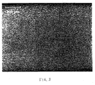
- Figure 3 shows a relatively fine-grained, homogenous, equiaxed lead alloy grain structure of the invention in the range of 10 - 30 microns.
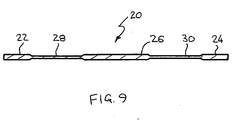
- Figure 9 illustrates a cross-section of a typical profile 20 of an extrusion of lead alloy suitable for expansion to a diamond design mesh such as shown in Figure 4 , by means of rotary expansion as described in detail in U.S. Patent No. 4,291,443 and No. 4,315,356 .
- rotary expansion in a preferred method of expansion expansion can be effected by reciprocating expansion, punching, machining, waterjet cutting, spark cutting or laser cutting.
- Exemplary profile 20 has relatively thick side edges 22, 24 and central portion 26, with thin intermediate sections 28, 30, to allow the provision of adequately thick lugs in finished battery plates for good grid support and good electrical connections while allowing the expansion of thin mesh strands between the lugs.
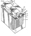
- Figure 10 illustrates a battery 100 having a plastic casing 102 with cover 104 including vent covers 106 containing extruded and expanded battery electrode plates produced by the method of the invention.
- the plates including paste 107 are stacked vertically as negative plates 72 alternating with positive plates 74 separated from one another by plate separators 112.
- the grid tabs 114 of negative plates 72 are interconnected by metal header 116 to negative battery post 118 and the grid tabs (not shown) of positive plates 74 are interconnected by metal header 122 to positive battery post 124.
- Sulphuric acid solution is added in an amount to submerge the battery plates for operating the battery.
- a good quality lead alloy required to obtain good results is typified by but not limited to an alloy comprising 0.05 - 0.09 Ca, 0.6 -1.8Sn, 0.01 - 0.06 Ag with the balance Pb. More preferred is the alloy 0.06 - 0.08Ca, 1.4-1.6 Sn, 0.010-0.035Ag, the balance Pb.
- a highly accurate control system that regulates the temperature in the extruder screw housing of the lead extruder within +/- 1°C for continuous extrusion, a water cooling system and strip drying system to control grain size, and a constant tension strip winder, are required.
- the lead extruder consists of a base frame, gearbox, lubrication unit for the gearbox, main motor, screwhousing, extrusion screw, cooling system for the screw housing, die block, feedpipes and inlet pipes and a melting pot, well-known in the art, as marketed by H. Folke Sandelin AB under the trade-mark the HANSSON-ROBERTSON continuous lead extruder.
- Lead alloy is loaded into the electrically heated melting pot and heated to a temperature of about 380°C.
- the molten alloy passes through the various zones of the melting pot, typically three zones, and then to the gravity feedpipe, via the melting pot outlet valve.
- the electrically heated feedpipe allows the alloy to pass through its omega construction to the straight inlet pipe and into the screwhousing.
- Liquid lead is very hygroscopic and can pass through openings that water cannot penetrate, so when the liquid material arrives at the screwhousing it needs to be made plastic before it can be transported by the rotating extrusion screw within the screwhousing. Regulated amounts of cooling water are applied to the three cooling zones of the screwhousing to reduce the alloy temperature below the melting point (melting point of lead is 327°C).
- the alloy is forced at pressures up to 2000 atmospheres (203MPa) into the die block.
- the die block forms the lead into the shape required as it passes through the die.
- the temperature of the material is approximately 200°C.
- the strip is cooled at preset positions (according to alloy) to achieve the desired grain size. The further away the cooling is from the die block exit, the larger the grain size will be.
- the output of the extruder varies depending on the alloy chosen. Pure lead and binary alloys of Pb-Sn can be output at up to 50 kg/min, whereas ternary and quaternary alloys have outputs of 23 - 30 kg/min.
- grain sizes should be kept in the range of about 100 - 300 microns. Very small grain sizes can lead to significant vertical growth due to the relatively straight grain boundary path through the thickness of the material. Very large grain sizes, with only 1- 2 grains through the thickness of the strip, can lead to the same problems for the same reason. Small grain sizes in the range of 10 - 30 microns however are suitable for negative alloy strip since the negative electrode is not subjected to corrosive attack due to the electrochemical characteristics of lead acid batteries.
- High tensile strength alloys are preferred, with high calcium alloy providing the best results.
- the key operating parameters are alloy choice and quenching position, which controls the grain size.
- Battery size grids are produced by the method desired.
- the bare, unpasted, grids are placed into a cell that contains 1.270sg sulphuric acid, at a temperature of 75°C.
- Counter negative electrodes of a typical negative alloy are placed between each positive grid that is to be tested. Typically each cell will hold between 4 and 16 positive grids for testing.
- a constant overpotential of 200mV versus the mercury reference electrode is applied to the positive grids.
- a control grid which is typically a cast PbCaSnAg alloy, expanded by rotary expansion, is used in order to set this potential. This test runs for 20 days, at which time the grids are removed and the maximum vertical growth of each grid is measured, and the grids are then stripped of corrosion product and the total weight loss is also determined. Comparisons of corrosion performance and vertical growth are then made with the control grid. Positive correlation between this type of accelerated bare grid test and pasted plate performance in batteries was observed.
- the Alloy C a CaSnAg alloy was chosen for further examination.
- the grain size was varied in order to determine what would be the best range for grain size with the extruded strip. It was decided to try three different grain sizes, one with very fine grains (20 - 30microns), one with large grains (400 - 500microns) and one with the grain size somewhere in between these extreme values (100 - 300microns).
- the extruded strip is by the most preferred of these methods when grid growth, which is directly correlated to battery life, is compared to the mass of the grid, which is directly related to both the cost of the battery to manufacture, as well as the fuel consumption of the vehicle that the battery will be placed in.
- Alloy C was the most preferable there is a wide alloy range that would provide acceptable results for strip used to produce battery electrodes, as seen in Figure 6 .
- the aging characteristics of the extruded strip are quite favourable.
- the extruded strip is significantly stronger than the conventional continuous cast strip.
- the conventional rolled material while initially stronger than the extruded strip overages significantly, as evidenced by the large decrease in tensile strength over time.
- the extruded strip, of a similar alloy does decrease slightly from the maximum strength achieved; however the decrease is minor compared to the drop shown in the rolled strip.
- the fine grain extruded material while aging slightly faster than the medium grain size extruded strip, has an overall lower strength over time.
Landscapes
- Chemical & Material Sciences (AREA)
- Chemical Kinetics & Catalysis (AREA)
- Electrochemistry (AREA)
- General Chemical & Material Sciences (AREA)
- Engineering & Computer Science (AREA)
- Manufacturing & Machinery (AREA)
- Cell Electrode Carriers And Collectors (AREA)
- Battery Electrode And Active Subsutance (AREA)
- Extrusion Of Metal (AREA)
Abstract
Description
- This invention relates to the continuous production of lead alloy strip and, more particularly, relates to the continuous high-speed extrusion of lead alloy strip for use as positive and negative electrodes of a lead-acid battery. The strip has a highly controlled microstructure which increases battery life by reducing the rate of vertical growth in the positive plate and reduces the rate of corrosion when compared with plates produced by other continuous processes. By reducing growth in the positive plate and by minimizing and forming a desired strip profile (e.g. by varying or tapering thickness from top to bottom of the strip) for the positive and negative alloy strip, the mass of both the positive and negative plates can be reduced, thereby reducing the overall weight and cost of batteries.
- In the production of lead-acid batteries there are several methods to produce the positive and negative grids used in the battery. In the continuous production of grids for lead-acid batteries these processes are limited to the production of either a rolled or cast strip which is punched or expanded by either reciprocating or rotary expansion processes or to the direct casting of grids, such as by the Concast™ process.
- The production of lead alloy strip for use as positive battery plates having limited plate growth is extremely important because plate growth can cause cell short circuits. This is a leading factor in shortening battery life in batteries made by continuous processes. The strip produced by conventional method such as rolling or continuous casting typically have a highly heterogenous microstructure with non-uniform grain sizes and shapes leading to undesirable plate growth and to corrosive attack from the battery electrolyte.
- The production of strip for negative plates also is commonly done by either continuous cast or rolling processes. The negative electrode is not subjected to corrosive attack due to the electrochemical characteristics of the electrode, and therefore the main focus of the negative strip is reducing the weight of the negative plate, while maintaining adequate conductivity. This is done by simply making the strip thinner, however if the lug is too thin there are problems in battery manufacturing, related to melting oflugs into the top lead.
- The extrusion of lead and lead alloys to provide a protective sheath on submersible cables to protect the cables from the corrosive effects of seawater, by means of extruding machines, has been done extensively in the past in the cable industry. Electrical cable is passed through the machine and a layer of lead alloy tube is extruded onto the cable. H.F. Sandelin is a world leader in the production of this type of machine. Other manufacturers include Pirelli, which produced a machine which is similar to the older Henley Extruder™ in utilizing a large horizontal screw. This type of apparatus has problems with alloy segregation and contamination of the screw.
-
U.S. Patent 4,332,629 describes the production of lead-antimony alloy strip by rarn-press extrusion. This process is limited to certain thicknesses and aspect ratios. Also, the process has limitations on production speed, this patent disclosing production rates of 6 - 10ft/min. (1.9 -3.2kg/min.). Strip produced by ram press extrusion has had negative results regarding corrosion and grid growth in laboratory testing. Also this process does not provide control of microstructure and grain size and is limited to alloy selection. -
JP 58-053158 A -
US 4,865,933 discloses a grid element for use in an electrochemical cell, comprising: a scrim woven from lengths of wire, each wire being a composite, continuous, electrically conductive wire comprising a core material and a coating of corrosion-resistant metal of substantially uniform thickness extruded onto the core material, the edge of said scrim being supported by a conductive frame.US 4,865,933 A discloses further a battery and a method of making a grid element for use in an electrochemical cell. - It is an object of the present invention to provide a method of continuously producing a lead alloy strip, a correspondingly extruded lead alloy strip for battery electrodes, a correspondingly expanded grid comprising the extruded lead alloy strip as well as a correspondingly lead acid battery comprising the expanded grid.
- The object of the present invention is achieved by the method according to claim 1. The object of the present invention is achieved by the extruded lead alloy strip according to
claim 10. The object of the present invention is achieved by the expanded grid according to claim 11. The object of the present invention is achieved by the lead acid battery to claim 12. - The objective of the present invention is to provide an extrusion method and apparatus that can economically produce superior extruded lead alloy strip of a desired profile for the production of positive and negative battery plates that are resistant to both vertical grid growth and weight loss through corrosion in lead-acid batteries. The strip is produced at a speed that is competitive with continuous cast and rolled strip, the extruded strip having superior qualities in any of the following areas; corrosion induced growth, corrosion weight loss, shape, grid weight, cost, and automation compared to conventional technologies.
- The preferred use of the invention is in the production of lead-alloy strip to be coiled for use in a continuous battery manufacturing line. This strip can be used to produce battery mesh by continuous reciprocating expansion of the strip into expanded mesh or by continuous rotary expansion of the strip into expanded mesh, such as disclosed in
U.S. Patents No. 4,315,356 issued February16, 1982 ,No. 4,291,443 issued September 29, 1981 ,No. 4,297,866 issued November 3, 1981 ,No. 5,462,109 issued October 31, 1995 , andNo. 5,896,635 issued April 27, 1999 to Cominco Ltd., incorporated herein by reference. The expanded mesh is then pasted and divided into individual battery plates that can be placed in a battery. - The minimum and maximum grain sizes of the extruded strip will vary with the thickness of the strip but can be controlled by means of rapid cooling with water spray after the strip exits the extruder die. The microstructure of extruded alloy strip is homogenous, stable and can be easily controlled through machine parameter adjustments. With the correct choice of alloy and grain size, the vertical growth of positive grids in the lead-acid battery, made with extruded strip, can be greatly reduced. When compared with the current continuous processes for strip production, the growth of the positive grid is reduced by 50-75% in common laboratory testing. Weight loss caused by corrosion of the grid is similar to that of grids produced from continuously cast strip, and is less than that of rolled strip or bookmold grids. In extrusion, the strip can have different grid thicknesses over the width of the strip by control of the strip profile. This allows plates to be made with very thin wires, while still having a lug thickness sufficient to overcome manufacturing problems associated with thinner lugs. This leads to a significant weight savings in the negative plate and reduces the overall weight and cost of the battery. It has been found that by modifying the die block to allow for strip production rather than tube production, planar high-quality lead alloy strip can be produced of a desired profile. By introducing a novel strip cooling system, which preferably is a water spray system outside of the extruder dieblock, the strip can be optimized in alloy composition, grain size and thickness for fabrication of battery plates for use in lead-acid batteries.
- The main advantage of the extrusion strip production method is the absolute control over the grain size and grain structure of the material. This allows for the optimization of these parameters for reducing corrosion, limiting corrosion induced growth, increasing strength, and manipulation of the aging process of the alloy.
- Specifically, there are eight areas for optimizing strip and the resultant grids in a battery.
- 1. Grain Size: Extrusion offers the possibility of controlling the actual grain size of the final product over a wide range, from 20 microns to 500 microns. It should be noted that the minimum grain size will be further influenced by strip thickness and strip alloy composition. While it is possible to produce grain sizes anywhere in this range by modifying the cooling distance from the dieblock exit or the cooling rate, it should be noted that for battery performance it is preferred that the grain size for positive electrodes be in the range of 100 - 500microns, most preferably in the range 100 - 300microns. This is because at very small grain sizes of less than 100 microns, e.g. 20 - 100 microns, the grain boundary path for corrosive attack is almost straight through the material along the boundaries of very many grains. At very large grain sizes of greater than 100 microns, the path is also quite straight along the path of only one or two grains. Negative electrodes, however, are not subjected to corrosive attack and small grain sizes down to 10-30 microns are acceptable.
- 2. Grain Structure: Extruded strip produces a homogenous, equiaxed grain structure that is unlike any other strip production method. In conventional continuous casting the grains are columnar and very long. This can lead to a very straight path for corrosion along grain boundaries through the entire thickness of the strip, leading to significant grid growth in the battery. Rolled strip has a very heterogeneous, stratified structure with significant defect structure throughout the thickness of the strip. While this structure does impart high strength, it also allows significant corrosive attack on the strip, leading to very high weight loss due to corrosive attack at the defect sites. The deformed grains simply are peeled away, layer by layer, by the corrosive attack. With the extruded strip, the equiaxed, homogenous structure, with an optimized grain size, having about 6 - 10 grains (100 - 300micron grain size) through the thickness of the material, provides a very limited defect structure and also presents a long and winding path for corrosive attack on the grain boundaries of positive electrodes. In order for corrosive product to penetrate the strip and proceed through the thickness of the strip, the grain boundary path would be quite long and would slow the process down significantly.
- 3. Strip Tolerance: The extruded strip can be produced with extremely accurate physical dimensions with strip thickness tolerances of+/- 0.025mm. There is no need to trim the edges of the resultant strip as it can be produced to the exact width that is required without affecting the properties of the strip near the edges.
- 4. Alloy: Extrusion offers a wide range of possible alloys, similar to that of continuous casting or rolled strip. There are some elements that should be avoided in the alloy composition for extruded strip. These include aluminum, bismuth and sulphur, which will preferentially deposit on the extrusion screw, increasing the friction on the screw as it transports the lead to the die block. At a certain point the friction forces will cause the lead to stop moving in the screw housing, leading to down time for maintenance and cleaning of the screw.
- 5. Lead Placement (Strip Profile): With extruded strip, the lead passes through a machined die in order to achieve the strip profile necessary (i.e. strip width and thickness). With this in mind the strip can be profiled such that there is sufficient lead thickness for lug welding and conductivity; however the wire thickness can be decreased in order to reduce the weight of either a positive or negative plate. It is most useful in the negative plate, since the thickness of the strip can be significantly reduced between the top and bottom borders of the grid. This can also be useful in relocation of metal in the positive grid for conductivity reasons.
- 6. Porosity of the Strip: It is well known that the extruded lead product has zero porosity. This has been extremely important in the submarine cable industry, as any level of porosity could lead to seawater intrusion and cable failure, at a huge expense to the owner/operator of the cable. Thus many tests have been done on the extruded product to prove that there is absolutely no porosity, which is desirable for battery strip since any defects such as porosity can lead to aggressive corrosion attack. In continuous cast strip the level of porosity is quite low, although there is some minor levels, depending on alloy composition, casting speed, etc. Rolled product can have significantly high levels of porosity due to inclusions and impurities that are trapped in the product during the rolling process. Book mold grids, while not continuous, have very high levels of porosity that can lead to plate failures due to very high weight loss through corrosion. The pores, which are defects in the product, lead to more surface area that is open to corrosion attack.
- 7. Grid Design: With the extruded strip the mechanical properties are quite impressive. There is a high initial tensile strength (which varies with alloy) and a very high elongation (>40%) before yield. This elongation stays high through the early aging process, which allows the use of high elongation tooling in a rotary expansion system. The use of higher elongation tooling allows the diamond design of battery grid mesh to be almost square, thereby bringing the SWD/LWD ratio close to 1. In the diamond the SWD is height from the top of the diamond to the bottom and the LWD is the width of the diamond. This will aid in reducing growth, as the material is physically stronger in the vertical direction with this type of geometry as compared to grids produced with conventional elongation tools. Conventional SWD/LWD ratios, as shown in
Figure 4 , are much less than 1. - 8. Aging of the Strip: It has been shown that both continuous cast and rolled strip product will suffer from overaging after a certain period of time, as shown in
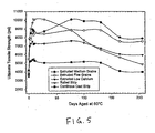
Figure 5 . This phenomenon, which is dependent on alloy composition and environmental conditions, significantly decreases the strength of the grid material, thereby increasing the possibility of grid growth. It has been shown that in standard 60°C aging tests, rolled strip will significantly overage after approximately 90 days. Continuous cast material, dependant on alloy composition, can extend this period. It has been found in extruded strip that the aging process continues for upwards of 130 days without any significant overaging. This does not seem to be dependant on the alloy composition, however there is some effect from the grain size, with the smaller grain sizes in the range of 10 to 30 microns having a lower overall strength reduction of approximately 10% after significant aging. - In its broad aspect, the method of producing a lead alloy strip for battery electrodes comprises extruding a lead alloy through a die block to produce an extrusion having a desired shape and rapidly cooling the extrusion to acquire a lead alloy grain size in the range of about 10 to 300 microns. More particularly, the method comprises extruding the lead alloy in the shape of a substantially planar profile or in the shape of a tube extrusion, slitting and opening the tube, and rolling the opened tube into a planar strip prior to rapidly cooling the extrusion. The planar strip preferably is cooled under tension and the cooled wound strip into a coil. The method additionally comprises slitting and expanding the cooled planar strip into an expanded grid by rotary expansion or by reciprocating expansion, punching, machining, waterjet cutting, spark cutting or laser cutting. Expanded grids are particularly suited for use as a battery electrode, such as in lead-acid batteries.
- The process of the invention and the products will now be described with reference to the accompanying drawings, in which:
- Figure 1
- is a photomicrograph of a cross-section of a conventional continuous cast strip of a typical alloy showing columnar or grain structure;
- Figure 2
- is a photomicrograph of a cross-section of a continuously extruded strip of an alloy produced according to the method of the present invention;
- Figure 3
- is a photomicrograph of a cross-section of a continuously extruded strip of an alloy produced according to the method of the present invention for use in negative electrode manufacture;
- Figure 4
- is a schematic plan view of a battery grid identifying grid components;
- Figure 5
- is a graph illustrating aging of extrusions produced according to the invention compared to aging characteristics of conventional materials;
- Figure 6
- is a graph showing vertical growth;
- Figure 7
- is a graph showing vertical growth for alloy C;
- Figure 8
- is a graph showing comparative vertical growth for a battery grid of the invention compared to conventional grids; and
- Figure 9
- is a cross-section of a typical strip extrusion, showing the strip profile; and
- Figure 10
- is a perspective view, partly cut away, of a battery having battery plate grids produced from strip extrusions of the invention.
- An H.F. Sandelin™ extruding machine was modified extensively in order to allow for the production of battery strip. The die block was re-engineered to allow for the production of flat strip rather than the conventional cable sheath, and the control system was modified to simplify the operation and to save space in crowded battery manufacturing facilities. The system was further modified by the addition of an outside strip cooling system that allows the lead alloy strip to exit the die block hot and to be cooled under controlled conditions to allow time for the grains to grow to the desired grain size. If the strip is cooled too soon, the grain size is very small, and if it is cooled too late, the grain size is very large. Although very fine or very coarse grain sizes can be produced, they are not optimal for use in battery production, due to poor performance under various tests conditions.
Figure 1 illustrates the columnar grain structure of a conventional, prior art continuously cast strip of a lead alloy.Figure 2 shows by comparison a homogenous equiaxed lead alloy grain structure of the invention having a grain size in the range of 100 - 300 microns.Figure 3 shows a relatively fine-grained, homogenous, equiaxed lead alloy grain structure of the invention in the range of 10 - 30 microns. -
Figure 9 illustrates a cross-section of atypical profile 20 of an extrusion of lead alloy suitable for expansion to a diamond design mesh such as shown inFigure 4 , by means of rotary expansion as described in detail inU.S. Patent No. 4,291,443 andNo. 4,315,356 . Although rotary expansion in a preferred method of expansion, expansion can be effected by reciprocating expansion, punching, machining, waterjet cutting, spark cutting or laser cutting.Exemplary profile 20 has relatively thick side edges 22, 24 andcentral portion 26, with thinintermediate sections -
Figure 10 illustrates abattery 100 having aplastic casing 102 withcover 104 including vent covers 106 containing extruded and expanded battery electrode plates produced by the method of the invention. Theplates including paste 107 are stacked vertically asnegative plates 72 alternating withpositive plates 74 separated from one another byplate separators 112. Thegrid tabs 114 ofnegative plates 72 are interconnected bymetal header 116 tonegative battery post 118 and the grid tabs (not shown) ofpositive plates 74 are interconnected bymetal header 122 to positive battery post 124. Sulphuric acid solution, not shown, is added in an amount to submerge the battery plates for operating the battery. - It should be noted that while it more preferable to produce flat strip having a desired profile by modifications to the die block, it is not absolutely necessary for the purposes of producing good quality battery strip. It is possible to produce a lead alloy tube and, by adding a knife edge to a conventional cable sheathing die, to slit the tube by the knife and subsequently open and flatten the tube. This opening and flattening process can be done either prior to the quenching of the metal or after the quenching. It is preferable to slit and open the tube prior to the quenching, due to the fact that it is mechanically easier to open the strip and flatten it while it is still at an elevated temperature. The Sandelin™ extruder is capable of production rates in excess of 78-156ft/min (25-50kg/min) or of strip, depending upon the alloy.
- A good quality lead alloy required to obtain good results, is typified by but not limited to an alloy comprising 0.05 - 0.09 Ca, 0.6 -1.8Sn, 0.01 - 0.06 Ag with the balance Pb. More preferred is the alloy 0.06 - 0.08Ca, 1.4-1.6 Sn, 0.010-0.035Ag, the balance Pb.
- A highly accurate control system that regulates the temperature in the extruder screw housing of the lead extruder within +/- 1°C for continuous extrusion, a water cooling system and strip drying system to control grain size, and a constant tension strip winder, are required.
- The lead extruder consists of a base frame, gearbox, lubrication unit for the gearbox, main motor, screwhousing, extrusion screw, cooling system for the screw housing, die block, feedpipes and inlet pipes and a melting pot, well-known in the art, as marketed by H. Folke Sandelin AB under the trade-mark the HANSSON-ROBERTSON continuous lead extruder.
- Lead alloy is loaded into the electrically heated melting pot and heated to a temperature of about 380°C. The molten alloy passes through the various zones of the melting pot, typically three zones, and then to the gravity feedpipe, via the melting pot outlet valve. The electrically heated feedpipe allows the alloy to pass through its omega construction to the straight inlet pipe and into the screwhousing. Liquid lead is very hygroscopic and can pass through openings that water cannot penetrate, so when the liquid material arrives at the screwhousing it needs to be made plastic before it can be transported by the rotating extrusion screw within the screwhousing. Regulated amounts of cooling water are applied to the three cooling zones of the screwhousing to reduce the alloy temperature below the melting point (melting point of lead is 327°C). Once transportation starts, the alloy is forced at pressures up to 2000 atmospheres (203MPa) into the die block. The die block forms the lead into the shape required as it passes through the die. At this point the temperature of the material is approximately 200°C. After extrusion the strip is cooled at preset positions (according to alloy) to achieve the desired grain size. The further away the cooling is from the die block exit, the larger the grain size will be.
- The output of the extruder varies depending on the alloy chosen. Pure lead and binary alloys of Pb-Sn can be output at up to 50 kg/min, whereas ternary and quaternary alloys have outputs of 23 - 30 kg/min.
- For satisfactory results for positive electrode strip, grain sizes should be kept in the range of about 100 - 300 microns. Very small grain sizes can lead to significant vertical growth due to the relatively straight grain boundary path through the thickness of the material. Very large grain sizes, with only 1- 2 grains through the thickness of the strip, can lead to the same problems for the same reason. Small grain sizes in the range of 10 - 30 microns however are suitable for negative alloy strip since the negative electrode is not subjected to corrosive attack due to the electrochemical characteristics of lead acid batteries.
- In the production of negative grid electrodes, high levels of calcium are typically added in order to increase the mechanical strength of the grid. This increases the ease of handling during manufacturing. With the level of calcium additions ranging from 0.08 to 0.10 wt%, there is often a high level of calcium loss due to oxidation during the production process, prior to the strip actually being fabricated. With the extruded strip, with a very fine grain size the initial age hardening is quicker than for other grain sizes. It is during this initial period of 2 - 3 days that handling is important. In order to achieve the same mechanical strength as a continuous cast negative strip with 0.08 wt% calcium, it is possible to produce an extruded strip with a lower level of calcium (0.05 - 0.07 wt% calcium). This will lead to less alloying elements required, which lowers the cost of production. Also, by the configuration of the melting pots in series with the extruder, oxidation of the lead alloy in the pot is minimized, thereby minimizing losses of calcium prior to strip production.
- High tensile strength alloys are preferred, with high calcium alloy providing the best results. Thus, the key operating parameters are alloy choice and quenching position, which controls the grain size.
- The product of the invention will now be described with reference to the following non-limitative examples. An accelerated test that has adequately screened grids produced from either conventional continuous cast strip, rolled strip or book mold processes is detailed as follows.
- Battery size grids are produced by the method desired. The bare, unpasted, grids are placed into a cell that contains 1.270sg sulphuric acid, at a temperature of 75°C. Counter negative electrodes of a typical negative alloy are placed between each positive grid that is to be tested. Typically each cell will hold between 4 and 16 positive grids for testing. A constant overpotential of 200mV versus the mercury reference electrode is applied to the positive grids. A control grid, which is typically a cast PbCaSnAg alloy, expanded by rotary expansion, is used in order to set this potential. This test runs for 20 days, at which time the grids are removed and the maximum vertical growth of each grid is measured, and the grids are then stripped of corrosion product and the total weight loss is also determined. Comparisons of corrosion performance and vertical growth are then made with the control grid. Positive correlation between this type of accelerated bare grid test and pasted plate performance in batteries was observed.
- Comparison with the results of typical rolled product and book mold grids were made. The results of the laboratory testing is shown in the tables below.
- Testing was done on several different alloys and each alloy was tested at different grain sizes, done by varying the quenching position of the strip after it exited the dieblock, as shown in
Figure 6 and tabulated in Table 1. Very small grain sizes, in the range of 10-30microns were also produced by running the extruder in the standard cable sheathing mode, with cooling internal to the dieblock.Table 1 Alloy Test Ca% Sn% Ag% Ba% Sr% Al% Average
Grain SizeExtruded A 0.00 0.88 0.062 0.00 0.035 0.00 150microns Extruded B 0.040 0.81 0.00 0.009 0.00 0.004 150microns Extruded C 0.060 1.66 0.033 0.00 0.00 0.00 150microns Extruded D 0.072 1.74 0.00 0.00 0.00 0.00 180microns - From these initial tests described above, the Alloy C, a CaSnAg alloy was chosen for further examination. The grain size was varied in order to determine what would be the best range for grain size with the extruded strip. It was decided to try three different grain sizes, one with very fine grains (20 - 30microns), one with large grains (400 - 500microns) and one with the grain size somewhere in between these extreme values (100 - 300microns).
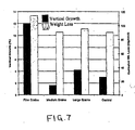
- The testing is summarized as illustrated in
Figure 7 . - All of the data shown in
Figure 7 are the average of multiple repeat tests. Each test will vary slightly due to ambient environmental changes, as well as small fluctuations in current and voltage during each test. - As can be seen from
Figure 7 , the medium grain Pb 0.06Ca 1.5Sn 0.03Ag (nominal) alloy, with the actual grain size averaging approximately 150 microns, was the best in this testing. - These results were compared with those of other continuous processes, as well as the incumbent book mold grids. The results are summarized in the chart of
Figure 8 . - The extruded strip is by the most preferred of these methods when grid growth, which is directly correlated to battery life, is compared to the mass of the grid, which is directly related to both the cost of the battery to manufacture, as well as the fuel consumption of the vehicle that the battery will be placed in.
- It should be noted that while the Alloy C was the most preferable there is a wide alloy range that would provide acceptable results for strip used to produce battery electrodes, as seen in
Figure 6 . - It is possible to produce a wide variety of battery alloys in the Sandelin™ extruder, over a wide range of grain sizes. By the choice of Alloy C, it is not intended to limit the scope of the alloys of the invention, but only to show one particular alloy, with a more specific grain size, that would be considered most preferred.
- Aging of the alloy is also quite impressive as indicated in the following graph, as illustrated in
Figure 5 . - As can be seen in the graph, the aging characteristics of the extruded strip are quite favourable. When compared to continuous cast and rolled strip of a similar alloy, there are significant differences. The extruded strip is significantly stronger than the conventional continuous cast strip. The conventional rolled material, while initially stronger than the extruded strip overages significantly, as evidenced by the large decrease in tensile strength over time. The extruded strip, of a similar alloy, does decrease slightly from the maximum strength achieved; however the decrease is minor compared to the drop shown in the rolled strip. Also, it is evident that the fine grain extruded material, while aging slightly faster than the medium grain size extruded strip, has an overall lower strength over time. The initial one to three days the strengths are similar, however the data shows the fine grain size material with a slightly higher strength during this short period. It is during this time that the material will be handled during manufacturing. Therefore, for the negative alloy strip, the fine grain size would add some needed strength to the material during the manufacturing and processing window.
- It will be understood, of course, that modifications can be made in the embodiments of the invention illustrated and described herein without departing from the scope and purview of the invention as defined by the appended claims.
Claims (12)
- A method of continuously producing a lead alloy strip having high initial tensile strength and elongation before yield greater than 40% for battery electrode plates characterized by heating a lead alloy to a temperature above the melting point of the lead alloy for feeding of molten lead alloy to an extruder having a screwhousing and a die block with a desired die profile, cooling the molten lead alloy within the screwhousing to a temperature below the melting point of the lead alloy for extrusion of the lead alloy through the die block, forcing the lead alloy through the die block at a pressure up to 2000 atmospheres to produce an extrusion with zero porosity having a desired strip profile and a homogeneous, equiaxed lead alloy grain structure, and rapidly cooling the extrusion by quenching while maintaining the extrusion under tension to acquire a strip having a homogeneous, equiaxed lead alloy grain structure with a predetermined grain size in the range of 10 to 300 microns, and winding the cooled extruded strip under tension into a coil.
- A method as claimed in claim 1, in which the lead alloy is heated to a temperature in a temperature range from the melting point of the lead alloy up to 380°C for feeding of molten lead alloy to the extruder.
- A method as claimed in claim 1 or 2, in which the lead alloy contains 0.05 to 0.07 wt% calcium, 0.6 to 1.8 wt% tin and the balance lead.
- A method as claimed in claim 1 or 2, in which the lead alloy comprises 0.05 - 0.09 wt% calcium, 0.6 - 1.8 wt% tin, 0.01 - 0.06 wt% silver and the balance lead.
- In a method as claimed in claim 1 or 2, extruding the lead alloy in the shape of a tube extrusion, slitting and opening the tube, and rolling the opened tube into a planar strip prior to rapidly cooling the extrusion.
- In a method as claimed in claim 1 or 2, extruding the lead alloy in the shape of a planar strip.
- A method as claimed in claim 6, extruding the lead alloy to produce an extrusion having a desired profile.
- A method as claimed in claim 6, additionally comprising slitting and expanding the cooled planar strip into an expanded diamond grid mesh by rotary expansion wherein the ratio of the height of the diamond to the width of the diamond of the diamond grid mesh is up to almost 1.
- A method as claimed in claim 6, additionally comprising forming the cooled planar strip into an expanded grid by reciprocating expansion, punching, machining, waterjet cutting, spark cutting or laser cutting.
- An extruded lead alloy strip for battery electrodes produced by the method of any of claims 1 through 9 characterized in that the lead alloy strip has zero porosity and high initial tensile strength and high elongation before yield greater than 40% with a homogeneous, equiaxed grain structure in the size range of 10 to 300 microns.
- An expanded grid comprising the extruded lead alloy strip of claim 10.
- A lead acid battery having a plurality of battery electrodes comprising the expanded grid of claim 11.
Applications Claiming Priority (3)
| Application Number | Priority Date | Filing Date | Title |
|---|---|---|---|
| CA2338168 | 2001-02-26 | ||
| CA002338168A CA2338168A1 (en) | 2001-02-26 | 2001-02-26 | Continuous extruded lead alloy strip for battery electrodes |
| PCT/CA2002/000210 WO2002069421A2 (en) | 2001-02-26 | 2002-02-20 | Continuous extruded lead alloy strip for battery electrodes |
Publications (2)
| Publication Number | Publication Date |
|---|---|
| EP1366532A2 EP1366532A2 (en) | 2003-12-03 |
| EP1366532B1 true EP1366532B1 (en) | 2010-12-01 |
Family
ID=4168433
Family Applications (1)
| Application Number | Title | Priority Date | Filing Date |
|---|---|---|---|
| EP02701126A Expired - Lifetime EP1366532B1 (en) | 2001-02-26 | 2002-02-20 | Continuous extruded lead alloy strip for battery electrodes |
Country Status (12)
| Country | Link |
|---|---|
| US (1) | US6797403B2 (en) |
| EP (1) | EP1366532B1 (en) |
| JP (1) | JP4380159B2 (en) |
| KR (1) | KR100758351B1 (en) |
| CN (1) | CN1305152C (en) |
| AT (1) | ATE490564T1 (en) |
| AU (1) | AU2002234457A1 (en) |
| BR (1) | BR0207417B1 (en) |
| CA (1) | CA2338168A1 (en) |
| DE (1) | DE60238469D1 (en) |
| MX (1) | MXPA03007498A (en) |
| WO (1) | WO2002069421A2 (en) |
Cited By (1)
| Publication number | Priority date | Publication date | Assignee | Title |
|---|---|---|---|---|
| WO2013139953A1 (en) | 2012-03-22 | 2013-09-26 | Vb Autobatterie Gmbh & Co. Kgaa | Producing electrodes for lead-acid batteries |
Families Citing this family (23)
| Publication number | Priority date | Publication date | Assignee | Title |
|---|---|---|---|---|
| US6274274B1 (en) | 1999-07-09 | 2001-08-14 | Johnson Controls Technology Company | Modification of the shape/surface finish of battery grid wires to improve paste adhesion |
| KR100566624B1 (en) | 2002-04-18 | 2006-03-31 | 후루카와 덴치 가부시키가이샤 | Leadbased alloy for lead storage battery, plate for lead storage battery and lead storage battery |
| WO2003092101A1 (en) * | 2002-04-26 | 2003-11-06 | The Furukawa Battery Co., Ltd. | Process for producing lead or lead alloy plate grid for lead storage battery and lead storage battery |
| JP4929558B2 (en) * | 2003-08-08 | 2012-05-09 | 株式会社Gsユアサ | Method for manufacturing lead-acid battery grid |
| EP3035422B1 (en) | 2005-05-23 | 2019-02-20 | Johnson Controls Technology Company | Battery grid |
| JP4983024B2 (en) * | 2006-01-12 | 2012-07-25 | パナソニック株式会社 | Method for producing expanded grid for lead-acid battery |
| US7976976B2 (en) | 2007-02-07 | 2011-07-12 | Rosecreek Technologies Inc. | Composite current collector |
| RU2477549C2 (en) | 2007-03-02 | 2013-03-10 | Джонсон Кэнтрэулз Текнолэджи Кампэни | Accumulator negative grid manufacture method |
| WO2009155949A1 (en) * | 2008-06-26 | 2009-12-30 | H. Folke Sandelin Ab | Metal extrusion of product comprising parts designed to be post-extrusion disconnected from each other |
| WO2010051848A1 (en) * | 2008-11-07 | 2010-05-14 | H. Folke Sandelin Ab | Methods and system for manufacturing lead battery plates |
| MX338843B (en) | 2010-03-03 | 2016-05-03 | Johnson Controls Tech Co | Battery grids and methods for manufacturing same. |
| KR101831423B1 (en) | 2010-04-14 | 2018-02-22 | 존슨 컨트롤스 테크놀러지 컴퍼니 | Battery, battery plate assembly, and method of assembly |
| US9748578B2 (en) | 2010-04-14 | 2017-08-29 | Johnson Controls Technology Company | Battery and battery plate assembly |
| ITPV20110011A1 (en) | 2011-05-25 | 2012-11-26 | Alessandro Mantovani | CUTTING AND ABLATION PROCESS FOR PRODUCTION OF LEAD GRIDS FOR ACCUMULATORS USING LASER BEAM |
| US9761883B2 (en) | 2011-11-03 | 2017-09-12 | Johnson Controls Technology Company | Battery grid with varied corrosion resistance |
| US9595360B2 (en) | 2012-01-13 | 2017-03-14 | Energy Power Systems LLC | Metallic alloys having amorphous, nano-crystalline, or microcrystalline structure |
| WO2014149254A2 (en) * | 2013-03-15 | 2014-09-25 | Dhar Subhash K | Metallic allyos having amorphous, nano-crystallline, or microcrystalline structure |
| DE202013012569U1 (en) | 2013-10-08 | 2017-07-17 | Johnson Controls Autobatterie Gmbh & Co. Kgaa | Grid arrangement for a plate-shaped battery electrode of an electrochemical accumulator and accumulator |
| DE102013111667A1 (en) | 2013-10-23 | 2015-04-23 | Johnson Controls Autobatterie Gmbh & Co. Kgaa | Grid arrangement for a plate-shaped battery electrode and accumulator |
| US20170084926A1 (en) | 2015-09-18 | 2017-03-23 | Mitek Holdings, Inc. | Battery grid and method of making |
| US12451493B2 (en) | 2017-01-27 | 2025-10-21 | Cps Technology Holdings Llc | Battery grid |
| CN113512726B (en) * | 2021-06-29 | 2023-04-21 | 杭州电子科技大学 | Method and device for preparing crevice corrosion of composite microstructure on high-hardness surface |
| CN114107854A (en) * | 2021-11-08 | 2022-03-01 | 天能电池集团(马鞍山)新能源科技有限公司 | Lead-based mesh belt heat treatment method and automatic transmission system based on lead-based mesh belt heat treatment method |
Citations (1)
| Publication number | Priority date | Publication date | Assignee | Title |
|---|---|---|---|---|
| JPS5853158A (en) * | 1981-09-25 | 1983-03-29 | Furukawa Battery Co Ltd:The | Working of lead-base alloy member for storage battery |
Family Cites Families (18)
| Publication number | Priority date | Publication date | Assignee | Title |
|---|---|---|---|---|
| US3189989A (en) * | 1963-05-20 | 1965-06-22 | Ass Elect Ind | Dispersion hardening of lead |
| GB1187305A (en) * | 1967-05-22 | 1970-04-08 | Dow Chemical Co | Process for production of Extruded Magnesium-Lithium Alloy Articles |
| US3929513A (en) * | 1968-07-25 | 1975-12-30 | Gould Inc | Lead alloy products |
| SE351791B (en) * | 1969-11-17 | 1972-12-11 | A Runevall | |
| US3756312A (en) * | 1970-12-28 | 1973-09-04 | American Hydrotherm Corp | Heat transfer system for a continuous lead extruder |
| CA1114241A (en) * | 1978-10-31 | 1981-12-15 | Cominco Ltd. | Forming expanded mesh sheet from deformable strip |
| ZA803745B (en) | 1979-06-29 | 1982-01-27 | Chloride Group Ltd | Electric storage batteries |
| JPS57130377A (en) * | 1981-02-05 | 1982-08-12 | Furukawa Battery Co Ltd:The | Manufacture of plate base for clad-type lead acid battery |
| US4658623A (en) * | 1984-08-22 | 1987-04-21 | Blanyer Richard J | Method and apparatus for coating a core material with metal |
| US4865933A (en) * | 1984-08-22 | 1989-09-12 | Blanyer Richard J | Battery grid structure made of composite wire |
| US5925470A (en) * | 1984-08-22 | 1999-07-20 | Blanyer; Richard J. | Coated elongated core material |
| JPS61114470A (en) * | 1984-11-08 | 1986-06-02 | Shin Kobe Electric Mach Co Ltd | Plate for lead storage battery |
| US5611128A (en) * | 1995-04-28 | 1997-03-18 | Wirtz Manufacturing Co., Inc. | Battery grids, method and apparatus |
| US5514494A (en) * | 1995-06-19 | 1996-05-07 | Corning Incorporated | Battery separator |
| US6342110B1 (en) * | 1996-03-01 | 2002-01-29 | Integran Technologies Inc. | Lead and lead alloys with enhanced creep and/or intergranular corrosion resistance, especially for lead-acid batteries and electrodes therefor |
| EP0795918A3 (en) * | 1996-03-12 | 2000-08-23 | Lucent Technologies Inc. | lead-acid battery with electrode structure, and method of making same |
| EP0795917A2 (en) * | 1996-03-12 | 1997-09-17 | Lucent Technologies Inc. | Lead-acid battery with corrosion resistant electrode structure, and method of making same |
| US6074576A (en) * | 1998-03-24 | 2000-06-13 | Therm-O-Disc, Incorporated | Conductive polymer materials for high voltage PTC devices |
-
2001
- 2001-02-26 CA CA002338168A patent/CA2338168A1/en not_active Abandoned
-
2002
- 2002-02-20 DE DE60238469T patent/DE60238469D1/en not_active Expired - Lifetime
- 2002-02-20 MX MXPA03007498A patent/MXPA03007498A/en active IP Right Grant
- 2002-02-20 AT AT02701126T patent/ATE490564T1/en not_active IP Right Cessation
- 2002-02-20 JP JP2002568440A patent/JP4380159B2/en not_active Expired - Lifetime
- 2002-02-20 AU AU2002234457A patent/AU2002234457A1/en not_active Abandoned
- 2002-02-20 CN CNB028055446A patent/CN1305152C/en not_active Expired - Lifetime
- 2002-02-20 KR KR1020037011167A patent/KR100758351B1/en not_active Expired - Lifetime
- 2002-02-20 WO PCT/CA2002/000210 patent/WO2002069421A2/en not_active Ceased
- 2002-02-20 BR BRPI0207417-6A patent/BR0207417B1/en not_active IP Right Cessation
- 2002-02-20 EP EP02701126A patent/EP1366532B1/en not_active Expired - Lifetime
- 2002-02-21 US US10/079,127 patent/US6797403B2/en not_active Expired - Lifetime
Patent Citations (1)
| Publication number | Priority date | Publication date | Assignee | Title |
|---|---|---|---|---|
| JPS5853158A (en) * | 1981-09-25 | 1983-03-29 | Furukawa Battery Co Ltd:The | Working of lead-base alloy member for storage battery |
Cited By (3)
| Publication number | Priority date | Publication date | Assignee | Title |
|---|---|---|---|---|
| WO2013139953A1 (en) | 2012-03-22 | 2013-09-26 | Vb Autobatterie Gmbh & Co. Kgaa | Producing electrodes for lead-acid batteries |
| DE102012102461A1 (en) | 2012-03-22 | 2013-09-26 | Vb Autobatterie Gmbh & Co. Kgaa | Process for the production of electrodes for lead-acid batteries, electrode and lead-acid battery produced thereafter |
| DE202012012740U1 (en) | 2012-03-22 | 2013-10-17 | Vb Autobatterie Gmbh & Co. Kgaa | Plant for the production of electrodes for lead-acid batteries |
Also Published As
| Publication number | Publication date |
|---|---|
| BR0207417A (en) | 2006-11-21 |
| DE60238469D1 (en) | 2011-01-13 |
| AU2002234457A1 (en) | 2002-09-12 |
| EP1366532A2 (en) | 2003-12-03 |
| US20020157743A1 (en) | 2002-10-31 |
| JP2005506654A (en) | 2005-03-03 |
| CN1305152C (en) | 2007-03-14 |
| ATE490564T1 (en) | 2010-12-15 |
| WO2002069421A2 (en) | 2002-09-06 |
| CA2338168A1 (en) | 2002-08-26 |
| BR0207417B1 (en) | 2012-06-26 |
| US6797403B2 (en) | 2004-09-28 |
| WO2002069421A3 (en) | 2003-09-25 |
| JP4380159B2 (en) | 2009-12-09 |
| MXPA03007498A (en) | 2003-12-08 |
| KR20040014464A (en) | 2004-02-14 |
| CN1636289A (en) | 2005-07-06 |
| KR100758351B1 (en) | 2007-09-14 |
Similar Documents
| Publication | Publication Date | Title |
|---|---|---|
| EP1366532B1 (en) | Continuous extruded lead alloy strip for battery electrodes | |
| EP0740357B1 (en) | Battery grids, manufacturing method and apparatus | |
| KR920007689B1 (en) | Electrode wire for wire discharge machining and its manufacturing method | |
| US6306523B1 (en) | Method of manufacturing porous electrode wire for electric discharge machining and structure of the electrode wire | |
| EP2738849B1 (en) | Aluminum alloy foil for electrode collector and production method therefor | |
| KR19990022736A (en) | Wire manufacturing method | |
| US20150037683A1 (en) | Reformed battery grids | |
| CN1011517B (en) | Process for strengthening lead-antimony alloys | |
| US6057059A (en) | Surface recrystallization of lead-alloy grid | |
| WO2011125555A1 (en) | Cu-zn alloy strip for tab material for connecting cells | |
| RU2136787C1 (en) | Copper wire and method of production of copper wire | |
| KR20150022906A (en) | Aluminum alloy foil for electrode collector, method for manufacturing same, and electrode material | |
| EP2738851A1 (en) | Aluminum alloy foil for electrode collectors and production method therefor | |
| US6802917B1 (en) | Perforated current collectors for storage batteries and electrochemical cells, having improved resistance to corrosion | |
| KR100617665B1 (en) | Manufacturing method of lead or lead alloy pole grid of lead acid battery and lead acid battery | |
| CA2438307C (en) | Continuous extruded lead alloy strip for battery electrodes | |
| US5830583A (en) | Copper wire | |
| JP2612137B2 (en) | Battery negative electrode zinc can | |
| JP2612138B2 (en) | Battery negative electrode zinc can | |
| JP4579514B2 (en) | Manufacturing method of grid substrate for lead acid battery | |
| EP0799665A1 (en) | Wire electrode for electro-discharge machining and method of manufacturing same | |
| KR100485645B1 (en) | The electrode wire for electrical discharge machining, and manufacturing method of it | |
| CN115198125A (en) | Preparation method and application of oxygen-free copper rod | |
| JPH11320268A (en) | Method of manufacturing electrode wire for electric discharge machining | |
| MXPA97001017A (en) | Copper thread and procedure for do |
Legal Events
| Date | Code | Title | Description |
|---|---|---|---|
| PUAI | Public reference made under article 153(3) epc to a published international application that has entered the european phase |
Free format text: ORIGINAL CODE: 0009012 |
|
| AK | Designated contracting states |
Kind code of ref document: A2 Designated state(s): AT BE CH CY DE DK ES FI FR GB GR IE IT LI LU MC NL PT SE TR |
|
| AX | Request for extension of the european patent |
Extension state: AL LT LV MK RO SI |
|
| 17P | Request for examination filed |
Effective date: 20030902 |
|
| 17Q | First examination report despatched |
Effective date: 20080331 |
|
| RAP1 | Party data changed (applicant data changed or rights of an application transferred) |
Owner name: TECK METALS LTD. |
|
| GRAP | Despatch of communication of intention to grant a patent |
Free format text: ORIGINAL CODE: EPIDOSNIGR1 |
|
| GRAS | Grant fee paid |
Free format text: ORIGINAL CODE: EPIDOSNIGR3 |
|
| GRAA | (expected) grant |
Free format text: ORIGINAL CODE: 0009210 |
|
| AK | Designated contracting states |
Kind code of ref document: B1 Designated state(s): AT BE CH CY DE DK ES FI FR GB GR IE IT LI LU MC NL PT SE TR |
|
| REG | Reference to a national code |
Ref country code: GB Ref legal event code: FG4D |
|
| REG | Reference to a national code |
Ref country code: CH Ref legal event code: EP |
|
| REG | Reference to a national code |
Ref country code: IE Ref legal event code: FG4D |
|
| REF | Corresponds to: |
Ref document number: 60238469 Country of ref document: DE Date of ref document: 20110113 Kind code of ref document: P |
|
| REG | Reference to a national code |
Ref country code: SE Ref legal event code: TRGR |
|
| REG | Reference to a national code |
Ref country code: NL Ref legal event code: VDEP Effective date: 20101201 |
|
| RAP2 | Party data changed (patent owner data changed or rights of a patent transferred) |
Owner name: H. FOLKE SANDELIN AB |
|
| PG25 | Lapsed in a contracting state [announced via postgrant information from national office to epo] |
Ref country code: NL Free format text: LAPSE BECAUSE OF FAILURE TO SUBMIT A TRANSLATION OF THE DESCRIPTION OR TO PAY THE FEE WITHIN THE PRESCRIBED TIME-LIMIT Effective date: 20101201 Ref country code: AT Free format text: LAPSE BECAUSE OF FAILURE TO SUBMIT A TRANSLATION OF THE DESCRIPTION OR TO PAY THE FEE WITHIN THE PRESCRIBED TIME-LIMIT Effective date: 20101201 Ref country code: FI Free format text: LAPSE BECAUSE OF FAILURE TO SUBMIT A TRANSLATION OF THE DESCRIPTION OR TO PAY THE FEE WITHIN THE PRESCRIBED TIME-LIMIT Effective date: 20101201 Ref country code: CY Free format text: LAPSE BECAUSE OF FAILURE TO SUBMIT A TRANSLATION OF THE DESCRIPTION OR TO PAY THE FEE WITHIN THE PRESCRIBED TIME-LIMIT Effective date: 20101201 |
|
| PG25 | Lapsed in a contracting state [announced via postgrant information from national office to epo] |
Ref country code: GR Free format text: LAPSE BECAUSE OF FAILURE TO SUBMIT A TRANSLATION OF THE DESCRIPTION OR TO PAY THE FEE WITHIN THE PRESCRIBED TIME-LIMIT Effective date: 20110302 |
|
| REG | Reference to a national code |
Ref country code: GB Ref legal event code: 732E Free format text: REGISTERED BETWEEN 20110704 AND 20110706 |
|
| PG25 | Lapsed in a contracting state [announced via postgrant information from national office to epo] |
Ref country code: BE Free format text: LAPSE BECAUSE OF FAILURE TO SUBMIT A TRANSLATION OF THE DESCRIPTION OR TO PAY THE FEE WITHIN THE PRESCRIBED TIME-LIMIT Effective date: 20101201 Ref country code: ES Free format text: LAPSE BECAUSE OF FAILURE TO SUBMIT A TRANSLATION OF THE DESCRIPTION OR TO PAY THE FEE WITHIN THE PRESCRIBED TIME-LIMIT Effective date: 20110312 Ref country code: PT Free format text: LAPSE BECAUSE OF FAILURE TO SUBMIT A TRANSLATION OF THE DESCRIPTION OR TO PAY THE FEE WITHIN THE PRESCRIBED TIME-LIMIT Effective date: 20110401 |
|
| REG | Reference to a national code |
Ref country code: DE Ref legal event code: R082 Ref document number: 60238469 Country of ref document: DE Representative=s name: MAIWALD PATENTANWALTSGESELLSCHAFT MBH, DE |
|
| PG25 | Lapsed in a contracting state [announced via postgrant information from national office to epo] |
Ref country code: MC Free format text: LAPSE BECAUSE OF NON-PAYMENT OF DUE FEES Effective date: 20110228 |
|
| REG | Reference to a national code |
Ref country code: CH Ref legal event code: PL |
|
| PLBE | No opposition filed within time limit |
Free format text: ORIGINAL CODE: 0009261 |
|
| STAA | Information on the status of an ep patent application or granted ep patent |
Free format text: STATUS: NO OPPOSITION FILED WITHIN TIME LIMIT |
|
| PG25 | Lapsed in a contracting state [announced via postgrant information from national office to epo] |
Ref country code: CH Free format text: LAPSE BECAUSE OF NON-PAYMENT OF DUE FEES Effective date: 20110228 Ref country code: DK Free format text: LAPSE BECAUSE OF FAILURE TO SUBMIT A TRANSLATION OF THE DESCRIPTION OR TO PAY THE FEE WITHIN THE PRESCRIBED TIME-LIMIT Effective date: 20101201 Ref country code: LI Free format text: LAPSE BECAUSE OF NON-PAYMENT OF DUE FEES Effective date: 20110228 |
|
| 26N | No opposition filed |
Effective date: 20110902 |
|
| REG | Reference to a national code |
Ref country code: DE Ref legal event code: R082 Ref document number: 60238469 Country of ref document: DE Representative=s name: MAIWALD PATENTANWALTSGESELLSCHAFT MBH, DE Effective date: 20110916 Ref country code: DE Ref legal event code: R081 Ref document number: 60238469 Country of ref document: DE Owner name: H. FOLKE SANDELIN AB, SE Free format text: FORMER OWNER: TECK METALS LTD., VANCOUVER, BRITISH COLUMBIA, CA Effective date: 20110916 Ref country code: DE Ref legal event code: R081 Ref document number: 60238469 Country of ref document: DE Owner name: H. FOLKE SANDELIN AB, SE Free format text: FORMER OWNER: TECK METALS LTD., VANCOUVER, CA Effective date: 20110916 Ref country code: DE Ref legal event code: R082 Ref document number: 60238469 Country of ref document: DE Representative=s name: MAIWALD PATENTANWALTS- UND RECHTSANWALTSGESELL, DE Effective date: 20110916 |
|
| REG | Reference to a national code |
Ref country code: IE Ref legal event code: MM4A |
|
| REG | Reference to a national code |
Ref country code: DE Ref legal event code: R097 Ref document number: 60238469 Country of ref document: DE Effective date: 20110902 |
|
| PG25 | Lapsed in a contracting state [announced via postgrant information from national office to epo] |
Ref country code: IT Free format text: LAPSE BECAUSE OF FAILURE TO SUBMIT A TRANSLATION OF THE DESCRIPTION OR TO PAY THE FEE WITHIN THE PRESCRIBED TIME-LIMIT Effective date: 20101201 |
|
| PG25 | Lapsed in a contracting state [announced via postgrant information from national office to epo] |
Ref country code: IE Free format text: LAPSE BECAUSE OF NON-PAYMENT OF DUE FEES Effective date: 20110220 |
|
| PG25 | Lapsed in a contracting state [announced via postgrant information from national office to epo] |
Ref country code: LU Free format text: LAPSE BECAUSE OF NON-PAYMENT OF DUE FEES Effective date: 20110220 |
|
| PG25 | Lapsed in a contracting state [announced via postgrant information from national office to epo] |
Ref country code: TR Free format text: LAPSE BECAUSE OF FAILURE TO SUBMIT A TRANSLATION OF THE DESCRIPTION OR TO PAY THE FEE WITHIN THE PRESCRIBED TIME-LIMIT Effective date: 20101201 |
|
| REG | Reference to a national code |
Ref country code: FR Ref legal event code: PLFP Year of fee payment: 14 |
|
| REG | Reference to a national code |
Ref country code: FR Ref legal event code: PLFP Year of fee payment: 15 |
|
| REG | Reference to a national code |
Ref country code: FR Ref legal event code: PLFP Year of fee payment: 16 |
|
| REG | Reference to a national code |
Ref country code: FR Ref legal event code: PLFP Year of fee payment: 17 |
|
| PGFP | Annual fee paid to national office [announced via postgrant information from national office to epo] |
Ref country code: FR Payment date: 20210119 Year of fee payment: 20 |
|
| PGFP | Annual fee paid to national office [announced via postgrant information from national office to epo] |
Ref country code: DE Payment date: 20210119 Year of fee payment: 20 Ref country code: SE Payment date: 20210118 Year of fee payment: 20 Ref country code: GB Payment date: 20210119 Year of fee payment: 20 |
|
| REG | Reference to a national code |
Ref country code: DE Ref legal event code: R071 Ref document number: 60238469 Country of ref document: DE |
|
| REG | Reference to a national code |
Ref country code: GB Ref legal event code: PE20 Expiry date: 20220219 |
|
| REG | Reference to a national code |
Ref country code: SE Ref legal event code: EUG |
|
| PG25 | Lapsed in a contracting state [announced via postgrant information from national office to epo] |
Ref country code: GB Free format text: LAPSE BECAUSE OF EXPIRATION OF PROTECTION Effective date: 20220219 |