EP1365517A2 - Input circuit for RF transmitter module - Google Patents
Input circuit for RF transmitter module Download PDFInfo
- Publication number
- EP1365517A2 EP1365517A2 EP03011577A EP03011577A EP1365517A2 EP 1365517 A2 EP1365517 A2 EP 1365517A2 EP 03011577 A EP03011577 A EP 03011577A EP 03011577 A EP03011577 A EP 03011577A EP 1365517 A2 EP1365517 A2 EP 1365517A2
- Authority
- EP
- European Patent Office
- Prior art keywords
- input circuit
- reference oscillator
- circuit according
- data signal
- transmitter module
- Prior art date
- Legal status (The legal status is an assumption and is not a legal conclusion. Google has not performed a legal analysis and makes no representation as to the accuracy of the status listed.)
- Withdrawn
Links
- 230000005540 biological transmission Effects 0.000 claims description 6
- 238000011045 prefiltration Methods 0.000 claims description 4
- 230000008878 coupling Effects 0.000 description 2
- 238000010168 coupling process Methods 0.000 description 2
- 238000005859 coupling reaction Methods 0.000 description 2
- 238000010586 diagram Methods 0.000 description 2
- 230000005611 electricity Effects 0.000 description 2
- XLYOFNOQVPJJNP-UHFFFAOYSA-N water Substances O XLYOFNOQVPJJNP-UHFFFAOYSA-N 0.000 description 2
- 239000003990 capacitor Substances 0.000 description 1
- 239000003795 chemical substances by application Substances 0.000 description 1
- 239000013078 crystal Substances 0.000 description 1
- 238000005516 engineering process Methods 0.000 description 1
- 239000010453 quartz Substances 0.000 description 1
- 230000001105 regulatory effect Effects 0.000 description 1
- VYPSYNLAJGMNEJ-UHFFFAOYSA-N silicon dioxide Inorganic materials O=[Si]=O VYPSYNLAJGMNEJ-UHFFFAOYSA-N 0.000 description 1
Images

Classifications
-
- H—ELECTRICITY
- H03—ELECTRONIC CIRCUITRY
- H03B—GENERATION OF OSCILLATIONS, DIRECTLY OR BY FREQUENCY-CHANGING, BY CIRCUITS EMPLOYING ACTIVE ELEMENTS WHICH OPERATE IN A NON-SWITCHING MANNER; GENERATION OF NOISE BY SUCH CIRCUITS
- H03B5/00—Generation of oscillations using amplifier with regenerative feedback from output to input
- H03B5/30—Generation of oscillations using amplifier with regenerative feedback from output to input with frequency-determining element being electromechanical resonator
- H03B5/32—Generation of oscillations using amplifier with regenerative feedback from output to input with frequency-determining element being electromechanical resonator being a piezoelectric resonator
- H03B5/36—Generation of oscillations using amplifier with regenerative feedback from output to input with frequency-determining element being electromechanical resonator being a piezoelectric resonator active element in amplifier being semiconductor device
- H03B5/366—Generation of oscillations using amplifier with regenerative feedback from output to input with frequency-determining element being electromechanical resonator being a piezoelectric resonator active element in amplifier being semiconductor device and comprising means for varying the frequency by a variable voltage or current
- H03B5/368—Generation of oscillations using amplifier with regenerative feedback from output to input with frequency-determining element being electromechanical resonator being a piezoelectric resonator active element in amplifier being semiconductor device and comprising means for varying the frequency by a variable voltage or current the means being voltage variable capacitance diodes
-
- H—ELECTRICITY
- H04—ELECTRIC COMMUNICATION TECHNIQUE
- H04B—TRANSMISSION
- H04B1/00—Details of transmission systems, not covered by a single one of groups H04B3/00 - H04B13/00; Details of transmission systems not characterised by the medium used for transmission
- H04B1/02—Transmitters
- H04B1/04—Circuits
- H04B1/0475—Circuits with means for limiting noise, interference or distortion
-
- H—ELECTRICITY
- H04—ELECTRIC COMMUNICATION TECHNIQUE
- H04L—TRANSMISSION OF DIGITAL INFORMATION, e.g. TELEGRAPHIC COMMUNICATION
- H04L27/00—Modulated-carrier systems
- H04L27/10—Frequency-modulated carrier systems, i.e. using frequency-shift keying
- H04L27/12—Modulator circuits; Transmitter circuits
-
- H—ELECTRICITY
- H03—ELECTRONIC CIRCUITRY
- H03B—GENERATION OF OSCILLATIONS, DIRECTLY OR BY FREQUENCY-CHANGING, BY CIRCUITS EMPLOYING ACTIVE ELEMENTS WHICH OPERATE IN A NON-SWITCHING MANNER; GENERATION OF NOISE BY SUCH CIRCUITS
- H03B2200/00—Indexing scheme relating to details of oscillators covered by H03B
- H03B2200/0002—Types of oscillators
- H03B2200/0008—Colpitts oscillator
Landscapes
- Engineering & Computer Science (AREA)
- Computer Networks & Wireless Communication (AREA)
- Signal Processing (AREA)
- Transmitters (AREA)
Abstract
Description
Die Erfindung betrifft eine Eingangsschaltung für einen integrierten HF-Sendebaustein eines batteriebetriebenen Geräts zur Übertragung eines Datensignals, wobei ein Referenzoszillator an einen der Eingänge des Sendebausteins angeschlossen ist.The invention relates to an input circuit for an integrated RF transmitter module a battery powered device for transmitting a Data signal, with a reference oscillator to one of the inputs of the Transmitter block is connected.
Derartige batteriebetriebene Geräte sind beispielsweise Verbrauchsmessgeräte, die zyklisch dem jeweiligen Verbrauchsstand entsprechende Funksignale senden, um den Verbrauchsstand für eine Verbrauchsabrechnung von ausserhalb des Gebäudes oder Raumes, in dem der Verbrauch stattfindet, erfassen zu können. Solche Verbrauchsmessgeräte können zur Erfassung des mittels eines Wasserzählers gemessenen Wasserverbrauchs oder des Wärmeverbrauchs an Heizkörpern oder des Stromverbrauchs dienen. Die Verbrauchsmessgeräte sollen kleinbauend und über mehrere Jahre wartungsfrei sein. Für den Betrieb solcher Geräte sind z. B. Funkfrequenzen von 433 MHz, 868 MHz und 915 MHz (USA ) freigegeben.Such battery-operated devices are, for example, consumption measuring devices that Send radio signals corresponding to the respective consumption level cyclically in order to the consumption level for a consumption bill from outside the Building or space in which consumption takes place. Such consumption meters can be used to detect the by means of a Water meter or measured water consumption or heat consumption Radiators or electricity consumption. The consumption measuring devices should small in size and maintenance-free for several years. For the operation of such Devices are e.g. B. Radio frequencies of 433 MHz, 868 MHz and 915 MHz (USA) Approved.
Als kostengünstiger HF-Sendebaustein ist der ASK/FSK-Transmitter 868/433 MHz TDA5100 oder TDA5102 (USA-Version) bzw. die TDA51xx-Familie der Fa. Infineon Technologys AG bekannt. Ähnliche Bausteine sind auch von anderen Herstellern bekannt. Bei der üblichen Beschaltung des Sendebausteins mit einem Referenzoszillator ist die übertragbare Datenrate auf etwa 20 kchip/s begrenzt. Dies ist ungünstig. Denn je niedriger die Datenrate ist, desto länger werden die Datentelegramme und desto größer wird der Stromverbrauch bei der Sendung der Datentelegramme. Ein hoher Stromverbrauch ist ungünstig, weil das batteriebetriebene Gerät jahrelang arbeiten soll, ohne dass die Batterien ausgetauscht oder nachgeladen werden müssen.The ASK / FSK transmitter 868/433 is a cost-effective RF transmitter MHz TDA5100 or TDA5102 (USA version) or the TDA51xx family of Infineon Technologys AG known. Similar building blocks are from others Manufacturers known. With the usual wiring of the transmitter module with a Reference oscillator, the transferable data rate is limited to about 20 kchip / s. This is inconvenient. Because the lower the data rate, the longer it gets Data telegrams and the greater the power consumption when sending the Data telegrams. A high power consumption is unfavorable because that battery powered device should work for years without the batteries need to be replaced or reloaded.
Aufgabe der Erfindung ist es, eine Eingangsschaltung der eingangs genannten Art vorzuschlagen, bei der die übertragene Datenrate sehr hoch gewählt werden kann.The object of the invention is an input circuit of the type mentioned to propose at which the transmitted data rate can be chosen to be very high.
Erfindungsgemäß ist obige Aufgabe durch die Merkmale des kennzeichnenden
Teils des Anspruchs 1 gelöst.According to the invention, the above object is characterized by the features of the
Part of
Durch die hohe Datenrate ist erreicht, dass die, beispielsweise eine Kennung und einen Zählerstand beinhaltenden, Datentelegramme jeweils sehr kurz dauern. Ihre Sendung verbraucht also entsprechend wenig Strom der Batterie. Um zugewährleisten, dass trotz der hohen Datenrate der bekannte HF-Sendebaustein zuverlässig arbeitet, wird die Amplitude des modulierten Datensignals begrenzt. Dadurch sind Spannungsspitzen und Spannungsschankungen des frequenzmodulierten Datensignals unterdrückt. Das Bandpassfilter hält störende Oberwellen und Schwebungen des modulierten Datensignals vom HF-Sendebaustein fern.The high data rate means that, for example, an identifier and data telegrams containing a counter reading each take a very short time. Your Consumption therefore consumes little battery power. Around ensure that, despite the high data rate, the well-known RF transmitter works reliably, the amplitude of the modulated data signal is limited. This causes voltage peaks and voltage fluctuations in the frequency-modulated data signal suppressed. The bandpass filter keeps annoying Harmonics and beats of the modulated data signal from the RF transmitter remote.
In weiterer Ausgestaltung der Erfindung ist das Datensignal über ein Vorfilter an den Referenzoszillator gelegt, das die Flankensteilheit des Datensignals verringert. Durch die verringerte Flankensteilheit sind Oberwellen des digitalen Datensignals schon vor dem Referenzoszillator unterdrückt.In a further embodiment of the invention, the data signal is on via a pre-filter the reference oscillator, which is the slope of the data signal reduced. Due to the reduced edge steepness, harmonics are digital Data signal suppressed before the reference oscillator.
Weitere vorteilhafte Ausgestaltungen der Erfindung ergeben sich aus den
Unteransprüchen und der folgenden Beschreibung eines Ausführungsbeispiels. In
der Zeichnung zeigen:
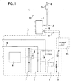
Der HF-Sendebaustein 1 ist der eingangs genannte TDA5100, an dessen Eingang
10 eine Eingangsschaltung 2 und an dessen Ausgang 14 eine Ausgangsschaltung
3 mit Antennenverstärker und Sendeantenne 4 liegt.The
Die Eingangsschaltung 2 weist einen Referenzoszillator 5 auf, der als Colpitts-Oszillator
aufgebaut ist. Er arbeitet mit einer Grundfrequenz von 6,788 MHz. An
seinem Schwingquarz 6 ist eine Modulationseinrichtung 7 angeschlossen, die mit
einer Kapazitätsdiode arbeitet. An diese ist über ein Vorfilter 8 das digitale
Datensignal (vgl. Fig. 2a) gelegt, das beispielsweise von einem Mikrocontroller
kommt, der dieses aus einem Messwert erzeugt.The
Am Ausgang des Referenzoszillators 5 liegt über ein Koppelglied 9 ein
Amplitudenbegrenzer 11 mit zwei Dioden. Zwischen den Amplitudenbegrenzer
11 und den Eingang 10 ist über weitere Koppelglieder 12,13 ein Bandpassfilter 15
geschaltet.At the output of the
Das Datensignal ist ein binäres Signal mit einer 3- aus 6-Kodierung. Seine Datenrate beträgt 100 kchip/s. Die Figur 2a zeigt nur einen Teil des Datensignals.The data signal is a binary signal with a 3 out of 6 coding. His Data rate is 100 kchip / s. Figure 2a shows only part of the data signal.
Das Vorfilter 8 verringert die Flankensteilheit des digitalen Datensignals (vgl. Fig.
2b). Mit dem gefilterten Datensignal wird die Grundfrequenz, beispielsweise
6,788 MHz, des Referenzoszillators 5 derart moduliert, dass beim
Spannungspegel H des Datensignals die Frequenz höher ist als beim
Spannungspegel L des Datensignals (vgl. Fig. 2c). Dieses modulierte Signal ist
noch von Spannungsspitzen und Oberwellen überlagert. Um die
Spannungsspitzen zu unterdrücken, reduziert der Amplitudenbegrenzer 11 die
Amplitude des frequenzmodulierten Referenzsignals, beispielsweise auf +/- 300
bis 600 mV (vgl. Fig. 2d).The pre-filter 8 reduces the slope of the digital data signal (see FIG.
2 B). With the filtered data signal, the fundamental frequency, for example
6.788 MHz, the
Das eine Spule und einen Kondensator aufweisende Bandpassfilter 15 begrenzt
die Bandbreite des modulierten Referenzsignals, um Oberwellen und
Schwebungen vor dem Eingang 10 des HF-Sendebausteins 1 zu unterdrücken.
Das Bandpassfilter 15 begrenzt die um die Grundfrequenz von etwa 6,788 MHz
liegende Bandbreite auf etwa 500 kHz (vgl. Fig. 2e). Damit ist das modulierte
Referenzsignal derart geglättet, dass es vom HF-Sendebaustein 1 trotz hoher
Datenrate störungsfrei verarbeitet werden kann.The
Der HF-Sendebaustein 1 arbeitet mit einer Trägerfrequenz von 868,95 MHz.
Diese Trägerfrequenz ist um den Faktor 128 höher als die Grundfrequenz des
Referenzoszillators 5. Im HF-Sendebaustein 1 ist ein PLL-Teiler (Phase-Locked-Loop-Divider)
mit dem Teilerfaktor 128 vorgesehen. Im HF-Sendebaustein 1 wird
die interne Frequenz von 868,95 MHz über den Teiler auf die Grundfrequenz von
6,788 MHz des Referenzoszillators 5 herabgesetzt und dann mit dem am Eingang
10 anstehenden frequenzmodulierten Referenzsignal verglichen. Entsprechend des
Vergleichs wird die Sendefrequenz von 868,95 MHz geregelt, so dass am
Ausgang 14 und damit an der Sendeantenne 4 ein entsprechend des
ursprünglichen Datensignals (vgl. Fig. 2a) moduliertes Sendesignal auftritt.The
Zur Stromersparnis sind der HF-Sendebaustein 1 und der Referenzoszillator 5
nicht ständig eingeschaltet, sondern werden vom genannten Mikrocontroller nur
zyklisch eingeschaltet. Beispielsweise erfolgt das Einschalten über
Einschaltleitungen 16 alle 4 s für 4 ms. Nur in diesen kurzen Zeitfenstem erfolgt
eine Sendung des Datensignals. Es hat sich gezeigt, dass diese kurzen Sendezeiten
genügen, um Zählerstände derart auszusenden, dass sie in einem einen
entsprechenden Empfänger mitführenden Fahrzeug empfangen werden können.
Es ist damit eine Zählerstandsablesung von außerhalb der Gebäude bzw. Räume,
in denen der Verbrauch stattfindet, auf einfache Weise möglich.To save electricity, the
Claims (12)
dadurch gekennzeichnet, dass die Grundfrequenz des Referenzoszillators (5) mit dem digitalen Datensignal moduliert ist, wobei die Datenrate größer als 20 kchip/s ist, und dass zwischen den Referenzoszillator (5) und den HF-Sendebaustein (1) ein Amplitudenbegrenzer (11) und ein Bandpassfilter (15) geschaltet ist.Input circuit for an integrated RF transmitter module of a battery-operated device for transmitting a data signal, a reference oscillator being connected to one of the inputs of the RF transmitter module,
characterized in that the fundamental frequency of the reference oscillator (5) is modulated with the digital data signal, the data rate being greater than 20 kchip / s, and in that an amplitude limiter (11) is located between the reference oscillator (5) and the RF transmitter module (1) and a bandpass filter (15) is connected.
dadurch gekennzeichnet, dass der Amplitudenbegrenzer (11) die Amplitude des frequenzmodulierten Datensignals auf etwa +/- 600 mV begrenzt.Input circuit according to claim 1,
characterized in that the amplitude limiter (11) limits the amplitude of the frequency-modulated data signal to approximately +/- 600 mV.
dadurch gekennzeichnet, dass das Bandpassfilter (15) die Bandbreite des frequenzmodulierten Datensignals auf etwa 500 kHz begrenzt.Input circuit according to claim 1,
characterized in that the bandpass filter (15) limits the bandwidth of the frequency-modulated data signal to approximately 500 kHz.
dadurch gekennzeichnet, dass das digitale Datensignal über ein Vorfilter (8) an den Referenzoszillator (5) gelegt ist, das die Flankensteilheit des Datensignals verringert.Input circuit according to one of the preceding claims,
characterized in that the digital data signal is applied to the reference oscillator (5) via a prefilter (8), which reduces the edge steepness of the data signal.
dadurch gekennzeichnet, dass das digitale Datensignal über eine eine Kapazitätsdiode aufweisende Modulationseinrichtung (7) an den Referenzoszillator (5) gelegt ist.Input circuit according to one of the preceding claims,
characterized in that the digital data signal is applied to the reference oscillator (5) via a modulation device (7) having a capacitance diode.
dadurch gekennzeichnet, dass der Referenzoszillator (5) ein Colpitts-Oszillator ist.Input circuit according to one of the preceding claims,
characterized in that the reference oscillator (5) is a Colpitts oscillator.
dadurch gekennzeichnet, dass die Grundfrequenz des Referenzoszillators (5) kleiner als die Sendefrequenz des HF-Sendebausteins (1) ist.Input circuit according to one of the preceding claims,
characterized in that the fundamental frequency of the reference oscillator (5) is lower than the transmission frequency of the RF transmission module (1).
dadurch gekennzeichnet, dass die Grundfrequenz des Referenzoszillators (5) etwa 6,788 MHz ist.Input circuit according to claim 7,
characterized in that the fundamental frequency of the reference oscillator (5) is approximately 6.788 MHz.
dadurch gekennzeichnet, dass die Sendefrequenz des HF-Sendebausteins (1) bei 868,95 MHz liegt.Input circuit according to one of the preceding claims 7, 8,
characterized in that the transmission frequency of the HF transmission module (1) is 868.95 MHz.
dadurch gekennzeichnet, dass die Datenrate 50 bis 120 kchip/s, insbesondere 100 kchip/s, beträgt.Input circuit according to one of the preceding claims,
characterized in that the data rate is 50 to 120 kchip / s, in particular 100 kchip / s.
dadurch gekennzeichnet, dass der HF-Sendebaustein (1) und der Referenzoszillator (5) zyklisch ein- und ausgeschaltet werden.Input circuit according to one of the preceding claims,
characterized in that the RF transmitter module (1) and the reference oscillator (5) are cyclically switched on and off.
dadurch gekennzeichnet, dass der HF-Sendebaustein (1) und der Referenzoszillator (5) etwa alle 4 s für 4 ms eingeschaltet sind.Input circuit according to claim 11,
characterized in that the RF transmitter module (1) and the reference oscillator (5) are switched on approximately every 4 s for 4 ms.
Applications Claiming Priority (2)
| Application Number | Priority Date | Filing Date | Title |
|---|---|---|---|
| DE10223396A DE10223396B4 (en) | 2002-05-25 | 2002-05-25 | Input circuit for an RF transmission block |
| DE10223396 | 2002-05-25 |
Publications (2)
| Publication Number | Publication Date |
|---|---|
| EP1365517A2 true EP1365517A2 (en) | 2003-11-26 |
| EP1365517A3 EP1365517A3 (en) | 2007-07-25 |
Family
ID=29285700
Family Applications (1)
| Application Number | Title | Priority Date | Filing Date |
|---|---|---|---|
| EP03011577A Withdrawn EP1365517A3 (en) | 2002-05-25 | 2003-05-22 | Input circuit for RF transmitter module |
Country Status (5)
| Country | Link |
|---|---|
| US (1) | US6885256B2 (en) |
| EP (1) | EP1365517A3 (en) |
| CN (1) | CN100534082C (en) |
| DE (1) | DE10223396B4 (en) |
| PL (1) | PL204897B1 (en) |
Cited By (1)
| Publication number | Priority date | Publication date | Assignee | Title |
|---|---|---|---|---|
| EP2360484A3 (en) * | 2010-01-22 | 2017-07-26 | Diehl Metering Systems GmbH | Bidirectional wireless data transmission method |
Citations (1)
| Publication number | Priority date | Publication date | Assignee | Title |
|---|---|---|---|---|
| WO1993020621A1 (en) | 1992-04-02 | 1993-10-14 | Stanford Telecommunications, Inc. | Method and apparatus for intermodulation noise suppression in rf power amplifiers |
Family Cites Families (8)
| Publication number | Priority date | Publication date | Assignee | Title |
|---|---|---|---|---|
| US3644831A (en) * | 1967-10-09 | 1972-02-22 | Gen Electric | Modulation system |
| US4755774A (en) * | 1985-07-15 | 1988-07-05 | Motorola Inc. | Two-port synthesizer modulation system employing an improved reference phase modulator |
| US5627529A (en) * | 1994-03-11 | 1997-05-06 | Prince Corporation | Vehicle control system with trainable transceiver |
| US5079526A (en) * | 1990-08-29 | 1992-01-07 | Motorola, Inc. | Frequency modulated synthesizer using low frequency offset mixed VCO |
| US5438329A (en) * | 1993-06-04 | 1995-08-01 | M & Fc Holding Company, Inc. | Duplex bi-directional multi-mode remote instrument reading and telemetry system |
| JPH08186519A (en) * | 1994-12-27 | 1996-07-16 | Sony Corp | Transmission/receptor circuit |
| IL117058A (en) * | 1996-02-06 | 2000-06-29 | Israel State | Millimeter-wave (MMW) synthesizer with FSK modulation transmitter |
| WO2002089327A1 (en) * | 2001-04-27 | 2002-11-07 | Koninklijke Philips Electronics N.V. | Switch in uhf bandpass |
-
2002
- 2002-05-25 DE DE10223396A patent/DE10223396B4/en not_active Expired - Fee Related
-
2003
- 2003-04-21 CN CNB031106250A patent/CN100534082C/en not_active Expired - Fee Related
- 2003-05-19 US US10/440,615 patent/US6885256B2/en not_active Expired - Fee Related
- 2003-05-22 EP EP03011577A patent/EP1365517A3/en not_active Withdrawn
- 2003-05-23 PL PL360323A patent/PL204897B1/en not_active IP Right Cessation
Patent Citations (1)
| Publication number | Priority date | Publication date | Assignee | Title |
|---|---|---|---|---|
| WO1993020621A1 (en) | 1992-04-02 | 1993-10-14 | Stanford Telecommunications, Inc. | Method and apparatus for intermodulation noise suppression in rf power amplifiers |
Cited By (1)
| Publication number | Priority date | Publication date | Assignee | Title |
|---|---|---|---|---|
| EP2360484A3 (en) * | 2010-01-22 | 2017-07-26 | Diehl Metering Systems GmbH | Bidirectional wireless data transmission method |
Also Published As
| Publication number | Publication date |
|---|---|
| EP1365517A3 (en) | 2007-07-25 |
| CN1459963A (en) | 2003-12-03 |
| CN100534082C (en) | 2009-08-26 |
| US20030218489A1 (en) | 2003-11-27 |
| DE10223396B4 (en) | 2005-08-04 |
| DE10223396A1 (en) | 2003-12-18 |
| PL204897B1 (en) | 2010-02-26 |
| US6885256B2 (en) | 2005-04-26 |
| PL360323A1 (en) | 2003-12-01 |
Similar Documents
| Publication | Publication Date | Title |
|---|---|---|
| DE3516810C2 (en) | ||
| US20080252366A1 (en) | Active Lc Band Pass Filter | |
| WO1999045499A1 (en) | Data medium for contactless reception of amplitude-modulated signals | |
| DE2660853C2 (en) | Wireless remote measuring device for physiological measured values of living beings | |
| DE3627226A1 (en) | SECURITY SYSTEM | |
| EP1365517A2 (en) | Input circuit for RF transmitter module | |
| DE3804592C1 (en) | Remote read-out system for consumption meter (electricity meter, supply meter) | |
| DE3426779C2 (en) | Arrangement for narrow-band filtering of the time signal of the transmitter DCF 77 | |
| WO2015055669A1 (en) | Wake-up receiver circuit | |
| DE102004024906B4 (en) | Clamping circuit for a receiver system | |
| DE2342345B2 (en) | Method for the transmission of the audio information received from a television or radio receiver via a wide beam of light | |
| DE19526635A1 (en) | Domestic equipment radio clock | |
| DE60217165T2 (en) | DIGITAL AUDIO BROADCASTING-V | |
| DE4342248A1 (en) | Communication device and method for its calibration | |
| DE812261C (en) | Power amplifier | |
| DE3641161C2 (en) | ||
| DE3720254C2 (en) | ||
| DE3618170A1 (en) | Arrangement for suppressing the transmission frequency of a radio-frequency transmitter at the input of an adjacent receiver | |
| DE102006035102B4 (en) | Hearing aid with a transceiver system | |
| DE624090C (en) | Receiving circuit in which the wave to be received is superimposed on a locally generated wave and the sum frequency of both is used | |
| DE2551863C3 (en) | Device for recording and remote transmission of physiological electrical signals | |
| EP0649226A2 (en) | Circuit arrangement for long-wave radio broadcast control receiver | |
| DE19707749B4 (en) | Circuit for generating a clock signal | |
| DE4427382A1 (en) | Receiver circuit for time sign signals | |
| DE3127947A1 (en) | Arrangement for transmitting digital signals according to the phase shift method |
Legal Events
| Date | Code | Title | Description |
|---|---|---|---|
| PUAI | Public reference made under article 153(3) epc to a published international application that has entered the european phase |
Free format text: ORIGINAL CODE: 0009012 |
|
| AK | Designated contracting states |
Kind code of ref document: A2 Designated state(s): AT BE BG CH CY CZ DE DK EE ES FI FR GB GR HU IE IT LI LU MC NL PT RO SE SI SK TR |
|
| AX | Request for extension of the european patent |
Extension state: AL LT LV MK |
|
| RAP1 | Party data changed (applicant data changed or rights of an application transferred) |
Owner name: HYDROMETER ELECTRONIC GMBH |
|
| PUAL | Search report despatched |
Free format text: ORIGINAL CODE: 0009013 |
|
| AK | Designated contracting states |
Kind code of ref document: A3 Designated state(s): AT BE BG CH CY CZ DE DK EE ES FI FR GB GR HU IE IT LI LU MC NL PT RO SE SI SK TR |
|
| AX | Request for extension of the european patent |
Extension state: AL LT LV MK |
|
| 17P | Request for examination filed |
Effective date: 20071009 |
|
| AKX | Designation fees paid |
Designated state(s): AT BE BG CH CY CZ DE DK EE ES FI FR GB GR HU IE IT LI LU MC NL PT RO SE SI SK TR |
|
| 17Q | First examination report despatched |
Effective date: 20100506 |
|
| STAA | Information on the status of an ep patent application or granted ep patent |
Free format text: STATUS: THE APPLICATION IS DEEMED TO BE WITHDRAWN |
|
| 18D | Application deemed to be withdrawn |
Effective date: 20121201 |