EP1365468A2 - Integrated condenser/separator for fuel cell exhaust gases - Google Patents
Integrated condenser/separator for fuel cell exhaust gases Download PDFInfo
- Publication number
- EP1365468A2 EP1365468A2 EP03006607A EP03006607A EP1365468A2 EP 1365468 A2 EP1365468 A2 EP 1365468A2 EP 03006607 A EP03006607 A EP 03006607A EP 03006607 A EP03006607 A EP 03006607A EP 1365468 A2 EP1365468 A2 EP 1365468A2
- Authority
- EP
- European Patent Office
- Prior art keywords
- gas flow
- coolant
- channels
- manifold
- outlet
- Prior art date
- Legal status (The legal status is an assumption and is not a legal conclusion. Google has not performed a legal analysis and makes no representation as to the accuracy of the status listed.)
- Withdrawn
Links
Images




Classifications
-
- B—PERFORMING OPERATIONS; TRANSPORTING
- B01—PHYSICAL OR CHEMICAL PROCESSES OR APPARATUS IN GENERAL
- B01D—SEPARATION
- B01D53/00—Separation of gases or vapours; Recovering vapours of volatile solvents from gases; Chemical or biological purification of waste gases, e.g. engine exhaust gases, smoke, fumes, flue gases, aerosols
- B01D53/26—Drying gases or vapours
- B01D53/265—Drying gases or vapours by refrigeration (condensation)
-
- B—PERFORMING OPERATIONS; TRANSPORTING
- B01—PHYSICAL OR CHEMICAL PROCESSES OR APPARATUS IN GENERAL
- B01D—SEPARATION
- B01D5/00—Condensation of vapours; Recovering volatile solvents by condensation
- B01D5/0003—Condensation of vapours; Recovering volatile solvents by condensation by using heat-exchange surfaces for indirect contact between gases or vapours and the cooling medium
- B01D5/0015—Plates
-
- B—PERFORMING OPERATIONS; TRANSPORTING
- B01—PHYSICAL OR CHEMICAL PROCESSES OR APPARATUS IN GENERAL
- B01D—SEPARATION
- B01D5/00—Condensation of vapours; Recovering volatile solvents by condensation
- B01D5/0033—Other features
- B01D5/0036—Multiple-effect condensation; Fractional condensation
-
- B—PERFORMING OPERATIONS; TRANSPORTING
- B01—PHYSICAL OR CHEMICAL PROCESSES OR APPARATUS IN GENERAL
- B01D—SEPARATION
- B01D5/00—Condensation of vapours; Recovering volatile solvents by condensation
- B01D5/0057—Condensation of vapours; Recovering volatile solvents by condensation in combination with other processes
-
- B—PERFORMING OPERATIONS; TRANSPORTING
- B01—PHYSICAL OR CHEMICAL PROCESSES OR APPARATUS IN GENERAL
- B01D—SEPARATION
- B01D5/00—Condensation of vapours; Recovering volatile solvents by condensation
- B01D5/0078—Condensation of vapours; Recovering volatile solvents by condensation characterised by auxiliary systems or arrangements
- B01D5/009—Collecting, removing and/or treatment of the condensate
-
- B—PERFORMING OPERATIONS; TRANSPORTING
- B01—PHYSICAL OR CHEMICAL PROCESSES OR APPARATUS IN GENERAL
- B01D—SEPARATION
- B01D5/00—Condensation of vapours; Recovering volatile solvents by condensation
- B01D5/0078—Condensation of vapours; Recovering volatile solvents by condensation characterised by auxiliary systems or arrangements
- B01D5/0093—Removing and treatment of non condensable gases
-
- F—MECHANICAL ENGINEERING; LIGHTING; HEATING; WEAPONS; BLASTING
- F28—HEAT EXCHANGE IN GENERAL
- F28B—STEAM OR VAPOUR CONDENSERS
- F28B1/00—Condensers in which the steam or vapour is separate from the cooling medium by walls, e.g. surface condenser
- F28B1/02—Condensers in which the steam or vapour is separate from the cooling medium by walls, e.g. surface condenser using water or other liquid as the cooling medium
-
- F—MECHANICAL ENGINEERING; LIGHTING; HEATING; WEAPONS; BLASTING
- F28—HEAT EXCHANGE IN GENERAL
- F28D—HEAT-EXCHANGE APPARATUS, NOT PROVIDED FOR IN ANOTHER SUBCLASS, IN WHICH THE HEAT-EXCHANGE MEDIA DO NOT COME INTO DIRECT CONTACT
- F28D9/00—Heat-exchange apparatus having stationary plate-like or laminated conduit assemblies for both heat-exchange media, the media being in contact with different sides of a conduit wall
- F28D9/0012—Heat-exchange apparatus having stationary plate-like or laminated conduit assemblies for both heat-exchange media, the media being in contact with different sides of a conduit wall the apparatus having an annular form
-
- F—MECHANICAL ENGINEERING; LIGHTING; HEATING; WEAPONS; BLASTING
- F28—HEAT EXCHANGE IN GENERAL
- F28D—HEAT-EXCHANGE APPARATUS, NOT PROVIDED FOR IN ANOTHER SUBCLASS, IN WHICH THE HEAT-EXCHANGE MEDIA DO NOT COME INTO DIRECT CONTACT
- F28D9/00—Heat-exchange apparatus having stationary plate-like or laminated conduit assemblies for both heat-exchange media, the media being in contact with different sides of a conduit wall
- F28D9/0031—Heat-exchange apparatus having stationary plate-like or laminated conduit assemblies for both heat-exchange media, the media being in contact with different sides of a conduit wall the conduits for one heat-exchange medium being formed by paired plates touching each other
- F28D9/0043—Heat-exchange apparatus having stationary plate-like or laminated conduit assemblies for both heat-exchange media, the media being in contact with different sides of a conduit wall the conduits for one heat-exchange medium being formed by paired plates touching each other the plates having openings therein for circulation of at least one heat-exchange medium from one conduit to another
-
- H—ELECTRICITY
- H01—ELECTRIC ELEMENTS
- H01M—PROCESSES OR MEANS, e.g. BATTERIES, FOR THE DIRECT CONVERSION OF CHEMICAL ENERGY INTO ELECTRICAL ENERGY
- H01M8/00—Fuel cells; Manufacture thereof
- H01M8/04—Auxiliary arrangements, e.g. for control of pressure or for circulation of fluids
- H01M8/04007—Auxiliary arrangements, e.g. for control of pressure or for circulation of fluids related to heat exchange
-
- H—ELECTRICITY
- H01—ELECTRIC ELEMENTS
- H01M—PROCESSES OR MEANS, e.g. BATTERIES, FOR THE DIRECT CONVERSION OF CHEMICAL ENERGY INTO ELECTRICAL ENERGY
- H01M8/00—Fuel cells; Manufacture thereof
- H01M8/04—Auxiliary arrangements, e.g. for control of pressure or for circulation of fluids
- H01M8/04007—Auxiliary arrangements, e.g. for control of pressure or for circulation of fluids related to heat exchange
- H01M8/04059—Evaporative processes for the cooling of a fuel cell
-
- H—ELECTRICITY
- H01—ELECTRIC ELEMENTS
- H01M—PROCESSES OR MEANS, e.g. BATTERIES, FOR THE DIRECT CONVERSION OF CHEMICAL ENERGY INTO ELECTRICAL ENERGY
- H01M8/00—Fuel cells; Manufacture thereof
- H01M8/04—Auxiliary arrangements, e.g. for control of pressure or for circulation of fluids
- H01M8/04082—Arrangements for control of reactant parameters, e.g. pressure or concentration
- H01M8/04089—Arrangements for control of reactant parameters, e.g. pressure or concentration of gaseous reactants
- H01M8/04119—Arrangements for control of reactant parameters, e.g. pressure or concentration of gaseous reactants with simultaneous supply or evacuation of electrolyte; Humidifying or dehumidifying
- H01M8/04156—Arrangements for control of reactant parameters, e.g. pressure or concentration of gaseous reactants with simultaneous supply or evacuation of electrolyte; Humidifying or dehumidifying with product water removal
-
- H—ELECTRICITY
- H01—ELECTRIC ELEMENTS
- H01M—PROCESSES OR MEANS, e.g. BATTERIES, FOR THE DIRECT CONVERSION OF CHEMICAL ENERGY INTO ELECTRICAL ENERGY
- H01M8/00—Fuel cells; Manufacture thereof
- H01M8/04—Auxiliary arrangements, e.g. for control of pressure or for circulation of fluids
- H01M8/04082—Arrangements for control of reactant parameters, e.g. pressure or concentration
- H01M8/04089—Arrangements for control of reactant parameters, e.g. pressure or concentration of gaseous reactants
- H01M8/04119—Arrangements for control of reactant parameters, e.g. pressure or concentration of gaseous reactants with simultaneous supply or evacuation of electrolyte; Humidifying or dehumidifying
- H01M8/04156—Arrangements for control of reactant parameters, e.g. pressure or concentration of gaseous reactants with simultaneous supply or evacuation of electrolyte; Humidifying or dehumidifying with product water removal
- H01M8/04164—Arrangements for control of reactant parameters, e.g. pressure or concentration of gaseous reactants with simultaneous supply or evacuation of electrolyte; Humidifying or dehumidifying with product water removal by condensers, gas-liquid separators or filters
-
- H—ELECTRICITY
- H01—ELECTRIC ELEMENTS
- H01M—PROCESSES OR MEANS, e.g. BATTERIES, FOR THE DIRECT CONVERSION OF CHEMICAL ENERGY INTO ELECTRICAL ENERGY
- H01M8/00—Fuel cells; Manufacture thereof
- H01M8/06—Combination of fuel cells with means for production of reactants or for treatment of residues
- H01M8/0662—Treatment of gaseous reactants or gaseous residues, e.g. cleaning
-
- B—PERFORMING OPERATIONS; TRANSPORTING
- B01—PHYSICAL OR CHEMICAL PROCESSES OR APPARATUS IN GENERAL
- B01D—SEPARATION
- B01D2258/00—Sources of waste gases
- B01D2258/02—Other waste gases
- B01D2258/0208—Other waste gases from fuel cells
-
- F—MECHANICAL ENGINEERING; LIGHTING; HEATING; WEAPONS; BLASTING
- F28—HEAT EXCHANGE IN GENERAL
- F28D—HEAT-EXCHANGE APPARATUS, NOT PROVIDED FOR IN ANOTHER SUBCLASS, IN WHICH THE HEAT-EXCHANGE MEDIA DO NOT COME INTO DIRECT CONTACT
- F28D21/00—Heat-exchange apparatus not covered by any of the groups F28D1/00 - F28D20/00
- F28D2021/0019—Other heat exchangers for particular applications; Heat exchange systems not otherwise provided for
- F28D2021/0043—Other heat exchangers for particular applications; Heat exchange systems not otherwise provided for for fuel cells
-
- F—MECHANICAL ENGINEERING; LIGHTING; HEATING; WEAPONS; BLASTING
- F28—HEAT EXCHANGE IN GENERAL
- F28F—DETAILS OF HEAT-EXCHANGE AND HEAT-TRANSFER APPARATUS, OF GENERAL APPLICATION
- F28F2250/00—Arrangements for modifying the flow of the heat exchange media, e.g. flow guiding means; Particular flow patterns
- F28F2250/10—Particular pattern of flow of the heat exchange media
- F28F2250/102—Particular pattern of flow of the heat exchange media with change of flow direction
-
- Y—GENERAL TAGGING OF NEW TECHNOLOGICAL DEVELOPMENTS; GENERAL TAGGING OF CROSS-SECTIONAL TECHNOLOGIES SPANNING OVER SEVERAL SECTIONS OF THE IPC; TECHNICAL SUBJECTS COVERED BY FORMER USPC CROSS-REFERENCE ART COLLECTIONS [XRACs] AND DIGESTS
- Y02—TECHNOLOGIES OR APPLICATIONS FOR MITIGATION OR ADAPTATION AGAINST CLIMATE CHANGE
- Y02E—REDUCTION OF GREENHOUSE GAS [GHG] EMISSIONS, RELATED TO ENERGY GENERATION, TRANSMISSION OR DISTRIBUTION
- Y02E60/00—Enabling technologies; Technologies with a potential or indirect contribution to GHG emissions mitigation
- Y02E60/30—Hydrogen technology
- Y02E60/50—Fuel cells
Definitions
- This invention relates to heat exchangers and liquid/gas separators, and more particularly, to condensers and liquid/gas separators for condensing and separating a condensate from a cathode exhaust gas flow in a fuel cell system, the condenser/separator comprising: a housing including a gas flow inlet, a gas flow outlet, a condensate outlet, a coolant inlet, a coolant outlet and a baffle plate positioned in the housing to divide an interior of the housing into a first gas flow chamber and a second gas flow chamber.
- An exemplary embodiment of the invention achieves at least some of the foregoing objects in an integrated condenser/separator for condensing and separating a condensate from a cathode exhaust gas flow in a fuel cell system.
- the condenser/separator includes a housing, a baffle plate positioned in the housing to divide the interior of the housing into a first gas flow chamber and a second gas flow chamber, and a plurality of heat exchange units arranged as a first stack of the heat exchange units positioned in the first gas flow chamber and a second stack of the heat exchanger units positioned in the second gas flow chamber.
- the housing includes a gas flow inlet, a gas flow outlet, a condensate outlet, a coolant inlet, and coolant outlet.
- a coolant opening is provided in the baffle plate to allow a flow of coolant through the baffle plate, a gas flow opening is provided in the baffle plate to allow a gas flow through the baffle plate.
- a first condensate drain is provided in the first gas flow chamber to drain condensate from the first gas flow chamber.
- the first stack of heat exchange units includes a first plurality of coolant channels interleaved with a first plurality of gas flow channels, a first inlet manifold to direct coolant into the first plurality of coolant channels, a first outlet manifold to receive coolant from the first plurality of coolant channels, and a first gas flow manifold to communicate gas flow with the first plurality of gas flow channels.
- the second stack includes a second plurality of coolant channels interleaved with a second plurality of gas flow channels, a second inlet manifold to direct coolant into the second plurality of coolant channels, a second outlet manifold that receives coolant from the second plurality of coolant channels, and a second gas flow manifold to communicate gas flow with the second plurality of gas flow channels.
- the first or second gas flow manifolds are aligned with 'the gas flow openings in 'the baffle plate so that *the gas flow makes one pass through the first plurality of gas flow channels and another pass through the second plurality of gas flow channels.
- the gas flow inlet opens into the first gas flow chamber, and the first and second gas flow manifolds are aligned with the gas flow openings in the baffle plate so that the gas flow makes a first pass from the first gas flow chamber through the first plurality of gas flow channels to the first gas flow manifold, flows from the gas flow manifold to the second gas flow manifold, and makes a second pass from the second gas flow manifold through the second plurality of second gas flow channels to the second gas flow chamber.
- a coalescing member is positioned upstream of the first and second plurality of gas flow channels.
- the integrated condenser/separator further includes a condensate manifold in fluid communication with the condensate outlet and the first condensate drain to direct condensate from the condensate drain to the condensate outlet.
- the condensate manifold includes a wall that surrounds at least part of the first and second gas flow chambers to define an exterior surface of the housing.
- the second outlet manifold and the first inlet manifold are aligned with the coolant opening in the baffle plate to allow coolant flow from the second outlet manifold to the first inlet manifold so that the coolant makes a pass through the second plurality of coolant channels and an additional pass through the first plurality of coolant channels.
- the baffle plate has an additional coolant opening
- the first and second inlet manifolds are aligned with one of the coolant openings in the baffle plate to allow coolant flow between the first and second inlet manifolds
- the first and second outlet manifolds are aligned with the other coolant openings in the baffle to allow coolant flow between the first and second outlet manifolds.
- each of the heat exchange units includes a pair of plates sealingly joined at peripheral edges to define a coolant channel in each of the heat exchange units, and the heat exchange units are spaced from each other to define the gas flow channels between the heat exchange units.
- the heat exchange units include respective sets of interconnected openings defining the inlet manifolds, the outlet manifolds, and the gas flow manifolds.
- the integrated condenser/separator further includes a second baffle plate positioned in the housing to divide the interior of the housing into a third gas flow chamber adjacent to the second gas flow chamber, a second condensate drain in the second gas flow chamber to drain condensate from the second gas flow chamber, and a third stack of heat exchange units positioned in the third gas flow chamber.
- the second baffle plate has a second coolant opening to allow a flow of coolant through the second baffle plate, and a second gas flow opening to allow a gas flow through the second baffle plate.
- the third stack includes a third plurality of coolant channels interleaved with a third plurality of gas flow channels, a third inlet manifold to direct coolant into the third plurality of coolant channels, a third outlet manifold to receive coolant from the third plurality of coolant channels, and a third gas flow manifold to communicate gas flow with a third plurality of gas flow channels.
- the gas flow inlet opens into the first gas flow chamber
- the first and second gas flow manifolds are aligned with the gas flow opening in the first baffle plate
- the third gas flow manifold is blocked by an imperforate portion of the second baffle plate so that the gas flow makes a first pass from the first gas flow chamber through the first plurality of gas flow channels to the first gas flow manifold, flows from the first gas flow manifold to the second gas flow manifold, makes a second pass from the second gas flow manifold through the second plurality of gas flow channels, flows through the gas flow opening in the second baffle plate to the third gas flow chamber, and makes a third pass from the third gas flow chamber through the third plurality of gas flow channels to the third gas flow manifold.
- an integrated condenser/separator 10 is provided for condensing and separating a condensate 11 from a cathode exhaust gas flow 12 of a fuel cell stack 13 in a fuel cell system 14.
- the condensate 11 is water
- the separated condensate 11 can be used for the purpose of humidifying the fuel cell inlet gasses, performing evaporative cooling of inlet -asses, and/of, supplying water for the various chemical reactions that occur within a hydrocarbon fuel processing system, as discussed in the Background of the Invention section of the present application.
- the condenser/separator 10 receives a flow of coolant 16 from the fuel cell system 14 for cooling the cathode exhaust gas flow 12.
- the coolant is returned to the fuel cell system 14.
- the components 15 will typically include a water tank, a methanol tank, a fuel vaporizer, a reformer and catalytic burner, a gas purification reactor, and a compressor/expander, all of which are known.
- Electric power generated by the fuel cell stack 13 is employed, during operation, to drive pumps, motors, etc. within the system as well as to provide electric power for a load to be driven by the system.
- the load will typically be a motor coupled to the vehicle traction system.
- the condenser/separator 10 includes a housing 17 centered about a vertical axis 18; first and second baffle plates 19 and 20 positioned in the housing 17 to divide the interior 22 of the housing 17 into first, second, and third gas flow chambers 24, 26, and 28; and a plurality of heat exchange units 30 arranged as a first stack 32 of the heat exchange units 30 positioned in the first gas flow chamber 24, a second stack 34 of the heat exchange units 30 positioned in the second gas flow chamber 26, and a third stack 36 of the heat exchange units 30 positioned in the third gas flow chamber 28.
- the first baffle plate 19 has a first coolant opening 38 to allow a flow of the coolant 16 through the baffle plate 19, and a gas flow opening 40 preferably centered in the baffle plate 19 to allow the gas flow 12 through the baffle plate 19.
- the second baffle plate 20 has a coolant opening 42 to allow the flow of coolant through the baffle plate 20, and preferably a plurality of upwardly flanged gas flow openings 44 equally spaced about an outer rim of the baffle plate 20 to allow the gas flow 12 through the baffle plate 20.
- the housing 17 includes a coolant inlet 48 directing the coolant 16 into the condenser/separator 10, a coolant outlet 50 for directing the coolant 16 away from the condense r/separator 10, a gas flow inlet 52 for directing the gas flow 12 into the condenser/separator 10, a gas flow outlet 54 for directing the gas flow 12 from the condenser/separator 10, and a condensate outlet 56 for directing the condensate 11 from the condenser/separator 10.
- the first stack 32 of the heat exchange units includes a first plurality of coolant channels 60 interleaved with a first plurality of gas flow channels 62, a first inlet manifold 64 to direct the coolant 16 into the first plurality of coolant channels 60, a first outlet manifold 66 to receive the coolant 16 from the first plurality of coolant channels 60, and a first gas flow manifold 68 to communicate the gas flow 12 with the first plurality of gas flow channels 62.
- the second stack 34 includes a second plurality of coolant channels 70 interleaved with a second plurality of gas flow channels 72, a second ;Inlet manifold 74 to direct the coolant 16 into the second plurality of coolant channels 70, a second outlet manifold 76 that receives the coolant 16 from the second plurality of coolant channel 70, and a second gas flow manifold 78 to communicate the gas flow 12 with the second plurality of gas flow channels 72.
- the third stack 36 includes a third plurality of coolant channels 80 interleaved with a third plurality of gas flow channels 82, a third inlet manifold 84 to direct the coolant 16 into the third plurality of coolant channels 80, a third outlet manifold 86 to receive the coolant 16 from the third plurality of coolant channel 80, and a third gas flow manifold 88 to communicate the gas flow 12 with the third plurality of gas flow channels 82.
- the coolant inlet 48 is aligned with and sealingly connected to the third inlet manifold 84 so that the coolant 16 is directed into the third inlet manifold 84, then makes a first pass through the third plurality of coolant channels 80 to the third outlet manifold 86, as shown by the arrowed lines in Fig. 3.
- the third outlet manifold 86 and the second inlet manifold 74 are aligned with the coolant opening 42 in the baffle plate 20 so that the coolant 16 flows from the third outlet manifold 86 to the second inlet manifold 74 and makes a second pass from the second inlet manifold 74 through the second plurality of coolant channels 70 to the second outlet manifold 76.
- the second outlet manifold 76 and the first inlet manifold 64 are aligned with the coolant opening 38 in the baffle plate 19, and the first outlet manifold 66 is aligned with and sealingly connected to coolant outlet 50 so that the coolant 16 flows from the second outlet manifold 76 to the first inlet manifold 64, makes a third pass from the first inlet manifold 64 through. the first plurality of coolant channels 60 to the first outlet manifold 66, and exits the condenser/separator 10 through the coolant outlet 50.
- the flow of the coolant through the condenser/separator 10 can be reversed by reversing the function of the coolant inlet 48 and the coolant outlet 50 so that the coolant 16 enters the condenser/separator 10 through the coolant outlet 50 and exits the condenser/separator 10 through the coolant inlet 48.
- each of the heat exchange units 30 comprises a pair of plates 90 sealing joined at their peripheral edges 92 to define one of the coolant channels 60, 70, 80 in each of the heat exchange units 30.
- each of the plates 90 is disc shaped with the peripheral edges 92 being substantially circular in shape.
- Each of the plates 90 includes a centrally located opening 94 that is sealingly joined with the opening 94 of the other plate 90 of the pair to define the respective gas flow manifolds 68, 78, and 88 of the first, second and third stack 32, 34, and 36.
- each of the plates 90 includes first and second flanged openings 96 and 98, with each of the first flanged openings 96 being sealingly joined to a flanged opening 96 of an adjacent heat exchange unit 30 to define the respective first, second, and third inlet manifolds 64, 74, and 84, and each of the second flanged openings 98 being connected with a flanged opening 98 of the adjacent heat exchange unit 30 to define the respective first, second and third outlet manifolds 66, 76, and 86.
- the top most plate 90 in the first stack 32 has only the flanged opening 98 which is aligned with the coolant outlet 50
- the bottom most plate 90 in the first stack 32 and the top most plate 90 in the second stack 34 have only the flanged openings 96 which are aligned with the coolant opening 38 in the baffle plate 19
- the bottom most plate 90 in the second stack 34 and the top most plate 90 in the third stack 36 have only the flanged openings 98 which are aligned with the coolant opening 42 in the baffle plate 20
- the bottom most plate 90 in the third stack 36 has only the flanged opening 96 which is aligned with the coolant inlet 48.
- suitable fins 97 such as lanced and offset fins, are provided in the gas flow channels 62, 72 and 82 between each of the heat exchange units 30.
- dimples formed in the plates 90 can be substituted for the fins 97.
- suitable turbulators, such as dimples 98 formed in the plates 90 or lanced and offset fins may be provided in each of the coolant flow channels 60, 70, and 80.
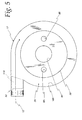
- each of the first, second and third gas flow chambers 24, 26, and 28 are bounded by respective cylindrical sidewalls 100, 102, and 104, and, as best seen in Fig. 5, the gas flow inlet 52 directs the gas flow 12 tangentially along the sidewall 100 into the first gas flow chamber 24 so that the gas flow 12 circulates about the axis 18 to help centrifuge condensate 11 from the gas flow 12.
- first and second condensate drains 106 and 108 are provided in the first and second gas flow chambers 24 and 26 respectively.
- each of the drains 106, 108 is provided in the form of a plurality of equally spaced openings 110 formed through the respective sidewalls 100 and 102.
- each of the baffle plates 19, 20 include a downwardly directed, cone shaped outer rim 112, 114 so that condensate 11 drains from the respective gas flow channels 62, 72 to the first and second condensate drains 106, 108.
- each of the openings 44 include an upwardly extending flange 116 to restrict the flow of condensate 11 through the openings 44.
- a condensate manifold 118 is defined by a cylindrical wall 120 that surrounds at least the portions of the walls 100 and 102 that include the openings 110 for the drains 106, 108 so that the condensate 11 is directed from the drains 106, 108 through the manifold 118 to the condensate outlet 56, as shown by the arrowed lines in Fig. 6.
- a coalescing pad or member 119 can optionally be provided in the gas flow inlet 52 to remove condensate that is already contained in the gas flow 12 prior to the gas flow 12 entering the plurality of gas flow channel 62.
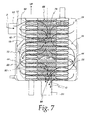
- the first gas flow manifold 68 and the second gas flow manifold 78 are aligned with the gas flow opening 40 in the baffle plate 19 so that the gas flow 12 makes a first pass from the first gas flow chamber 24 through the first plurality of gas flow channels 62 to the first gas flow manifold 68, flows from the first gas flow manifold 68 to the second gas flow manifold 78, and then makes a second pass from the second gas flow manifold 78 through the second plurality of gas flow channels 72 to the second gas flow chamber 26, as shown by the arrowed lines in Fig. 7.
- the gas flow outlet 54 is aligned with the third gas flow manifold 88 so that the gas flow 12 passes through the plurality of gas flow openings 44 in the second baffle plate 20 into the third gas flow chamber 28, makes a third pass through the third plurality of gas flow channels 88 to the third gas flow manifold 88, and exits the condenser/separator 10 via the gas flow outlet 54.
- Figs. 1 through 7 show an equal number of heat exchange units 30 in the three gas flow chambers 24, 26, and 28, it may be desirable in some applications for there to be an unequal number of the heat exchange units 30 in one or more of the gas flow chambers 24, 26, and 28.
- the condenser/separator 10 shown in Figs. 1-5 has three gas flow chambers 24, 26, and 28 and three stacks 32, 34 and 36 of the heat exchange units 30, it may be desirable in some applications to have more than, or less than three gas flow chambers and associated stacks of heat exchanger units 30.
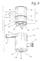
- FIG 8 shows one example of a condenser/separator 10 having only two gas flow chambers 24, 26 and two stacks 32, 34 of the heat exchange units 30, rather than three, as well as an unequal number of the heat exchange units 30 in each of the stacks 32 and 34 heat exchange units 30 are shown only schematically.
- the condenser/separator 10 in Figs. 1-7 show a three pass arrangement for the coolant flow 16 through the condenser/separator 10, it may be desirable of some applications for there to be more than, or fewer than three passes of coolant flow 16 through the condenser/separator 10.
- FIG. 1-7 shows the main body of the housing 17 being a four piece nested construction, with three inverted cup shaped pieces 130, 132 and 134 defining the first second and third gas flow chambers 24, 26 and 28, the baffle plates 19 and 20 being unitary parts of the cups pieces 132 and 134, respectively and an upwardly opening cup shaped piece 136 defining the condensate manifold 118, and the bottom of the housing 17, many other constructions are possible. For example, as shown in Fig.
- the main body of the housing 17 could be provided by an opened ended can shaped member 138, with one or more of the baffle plates 19, 20 being defined by a disk shaped member 140 that engages a cylindrical interior wall 142 of the can shaped member 138, and with the drain openings 110 being provided by cutouts 144 in the periphery of the disk shaped members 140 to allow the condensate to drain down the wall 142.
- Fig. 9 Another example of a possible housing modification is shown in Fig. 9 wherein the main body of the housing 17 is defined by three upwardly opening cup shaped members 150,152 and 154 that define the gas flow chambers 24, 26 and 28, respectively, a fourth upwardly opening member 156 that defines the condensate manifold 118, and a lid 158.
- the sidewalls 100, 102, 104 each have a downwardly converging conical shape instead of a cylindrical shape 1 58. It is believed that the downwardly converging conical shape may assist in the separation of the condensate 11 from the gas flow 12.
- the coalescing member 119 could be provided inside the first gas flow chamber 24 surrounding the heat exchange units 30, rather then in the gas flow inlet 52. Such a construction is shown by the cylindrical coalescing member 19 shown by broken lines in Fig. 9.
- the condensate manifold 118 could be provided by an inverted cup 160 that is fed condensate by channels 162 formed in a bottom 164 of the housing 17, such as is shown in Fig. 8.
- the components of the condenser/separator 10 are formed from a suitable material, such as aluminum, with the components being sealing connected by a suitable bonding method, such as brazing, as is well known from the "donut oil cooler” art.
- the condenser/separator 10 can provide a compact solution in comparison to conventional systems that employ separate devices.
- the condenser/separator 10 can be configured into any reasonable and independent number of coolant and gas sight passes as may be required to meet the thermal dynamic and pressure drop requirements of each particular application.
Landscapes
- Chemical & Material Sciences (AREA)
- Engineering & Computer Science (AREA)
- Chemical Kinetics & Catalysis (AREA)
- General Chemical & Material Sciences (AREA)
- Sustainable Energy (AREA)
- Life Sciences & Earth Sciences (AREA)
- Sustainable Development (AREA)
- Electrochemistry (AREA)
- Manufacturing & Machinery (AREA)
- Physics & Mathematics (AREA)
- Thermal Sciences (AREA)
- Mechanical Engineering (AREA)
- General Engineering & Computer Science (AREA)
- Analytical Chemistry (AREA)
- Oil, Petroleum & Natural Gas (AREA)
- Fuel Cell (AREA)
Abstract
Description
a housing including a gas flow inlet, a gas flow outlet, a condensate outlet, a coolant inlet, a coolant outlet and a baffle plate positioned in the housing to divide an interior of the housing into a first gas flow chamber and a second gas flow chamber.
For example, because fuel cells offer advantages in efficiency and in emission, interest in utilizing fuel cells as electricity generating plants and/or as a power source for vehicles has been increasing as concerns grow over the supply of fossil-fuel and the environmental effects of conventional fossil-fuel power sources, such as internal combustion engines for vehicles. However, improvements in affordability and compactness may be required before fuel cells become acceptable for widespread usage, particularly in vehicles.
It is another object of the invention to provide a relatively compact construction for a condenser and liquid/gas separator for fuel cell exhaust gas.
An exemplary embodiment of the invention achieves at least some of the foregoing objects in an integrated condenser/separator for condensing and separating a condensate from a cathode exhaust gas flow in a fuel cell system. The condenser/separator includes a housing, a baffle plate positioned in the housing to divide the interior of the housing into a first gas flow chamber and a second gas flow chamber, and a plurality of heat exchange units arranged as a first stack of the heat exchange units positioned in the first gas flow chamber and a second stack of the heat exchanger units positioned in the second gas flow chamber. The housing includes a gas flow inlet, a gas flow outlet, a condensate outlet, a coolant inlet, and coolant outlet. A coolant opening is provided in the baffle plate to allow a flow of coolant through the baffle plate, a gas flow opening is provided in the baffle plate to allow a gas flow through the baffle plate. A first condensate drain is provided in the first gas flow chamber to drain condensate from the first gas flow chamber. The first stack of heat exchange units includes a first plurality of coolant channels interleaved with a first plurality of gas flow channels, a first inlet manifold to direct coolant into the first plurality of coolant channels, a first outlet manifold to receive coolant from the first plurality of coolant channels, and a first gas flow manifold to communicate gas flow with the first plurality of gas flow channels. The second stack includes a second plurality of coolant channels interleaved with a second plurality of gas flow channels, a second inlet manifold to direct coolant into the second plurality of coolant channels, a second outlet manifold that receives coolant from the second plurality of coolant channels, and a second gas flow manifold to communicate gas flow with the second plurality of gas flow channels.
Claims (22)
- An integrated condenser/separator (10) for condensing and separating a condensate (11) from a cathode exhaust gas flow (12) in a fuel cell system, the condenser/separator (10) comprising:characterized in that,a housing (17) including a gas flow inlet (52), a gas flow outlet (54), a condensate outlet (56), a coolant inlet (48), and a coolant outlet (50); anda baffle plate (19) positioned in the housing (17) to divide an interior of the housing (17) into a first gas flow chamber (24) and a second gas flow chamber (26),
the baffle plate (19) having a coolant opening (38) to allow a flow of coolant (16) through the baffle plate (19) and a gas flow opening (40) to allow a gas flow through the baffle plate (19,);
a first condensate drain (106) in the first gas flow chamber (24) to drain condensate from the first gas flow chamber (24); and
a plurality of heat exchange units (30) arranged as a first stack (32) of the heat exchange units positioned in the first gas flow chamber (24) and a second stack (34) of the heat exchange units (30) positioned in the second gas flow chamber (26),
the first stack (32) including a first plurality of coolant channels (60) interleaved with a first plurality of gas flow channels (62), a first inlet manifold (64) to direct coolant (16) into the first plurality of coolant channels (60), a first outlet manifold (66) to receive coolant from the first plurality of coolant channels (60), and a first gas flow manifold (68) to communicate gas flow (12) with the first plurality of gas flow channels (62),
the second stack (34) including a second plurality of coolant channels (70) interleaved with a second plurality of gas flow channels (72), a second inlet manifold (74) to direct coolant into the second plurality of coolant channels (70), a second outlet manifold (76) that receives coolant (16) from the second plurality of coolant channels (70), and a second gas flow manifold (78) to communicate gas flow with the second plurality of gas flow channels (72). - The integrated condenser/separator of claim 1 wherein the first and second gas flow manifolds (68, 78) are aligned with the gas flow opening (40) in the baffle plate (19) whereby the gas flow (12) makes one pass through the first plurality of gas flow channels (62) and another pass through the second plurality of gas flow channels (72).
- The integrated condenser/separator of claims 1 or 2 wherein the gas flow inlet (52) opens into the first gas flow chamber (24) whereby the gas flow (12) makes a first pass from the first gas flow chamber (24) through the first plurality of gas flow channels (62) to the first gas flow manifold (68), flows from the first gas flow manifold (68) through the gas flow opening (40) to the second gas flow manifold (78), and makes a second pass from the second gas flow manifold (78) through the second plurality of gas flow channels (72) to the second gas flow chamber (26).
- The integrated condenser/separator of claim 1 wherein the housing (17) comprises cylindrical side walls (130, 132, 134, 138) surrounding the peripheries of the first and second stack (32, 34) of heat exchanger units (30).
- The integrated condenser/separator of claim 1 further comprising a coalescing member (119) positioned upstream of the first and second plurality of gas flow channels (62, 72).
- The integrated condenser/separator of claim 1 further comprising:a condensate manifold (118, 162) in fluid communication with the condensate outlet (56) and the first condensate drain (106, 144) to direct condensate from the condensate drain (106, 144) to the condensate outlet (56).
- The integrated condenser/separator of claim 6 wherein the condensate manifold (118) comprises a wall (120, 156) that surrounds at least parts of the first and second gas flow chambers (24, 26) to define an exterior surface of the housing (17).
- The integrated condenser/separator of claim 1 wherein said housing (17) comprises a first downwardly converging conical side wall (100), surrounding the periphery of the first stack (32) of heat exchanger units (30), and a second downwardly converging conical side wall (102, 104) surrounding the periphery of the second stack (34) of heat exchanger units (30).
- The integrated condenser/separator of claim 1 wherein the second outlet manifold and the first inlet manifold are aligned with the coolant opening (38) in the baffle plate (19) to allow coolant flow from the second outlet manifold to the first inlet manifold whereby the coolant makes a pass through the second plurality of coolant channels (70) and an additional pass through the first plurality of coolant channels (60).
- The integrated condenser/separator of claim 1 wherein the baffle plate (19) has an additional coolant opening (42), the first and second inlet manifolds are aligned with one of the coolant opening (42) in the baffle plate (19) to allow coolant flow between the first and second inlet manifolds,
the first and second outlet manifolds are aligned with the other coolant opening (42) in the baffle plate to (19) allow coolant flow between the first and second outlet manifolds. - The integrated condenser/separator of claim 1 further comprising:a second baffle plate (20) positioned in the housing (17) to divide the interior of the housing (17) into a third gas flow chamber (28) adjacent the second gas flow chamber (26), the second baffle plate (20) having a second coolant opening to allow a flow of coolant through the second baffle plate (20) and a second gas flow opening to allow a gas flow through the second baffle plate (20);a second condensate drain (108) in the second gas flow chamber (26) to drain condensate from the second gas flow chamber (26);and a third stack (36) of the heat exchange units (30) positioned in the third gas flow chamber (28), the third stack (36) including a third plurality of the coolant channels (80) interleaved with a third plurality of gas flow channels (82), a third inlet manifold to direct coolant into the third plurality of coolant channels (80), a third outlet manifold to receive coolant from the third plurality of coolant channels (80), and a third gas flow manifold to communicate gas flow with the third plurality of gas flow channels (82).
- An integrated condenser/separator (10) for condensing and separating a condensate (11) from a cathode exhaust gas flow (12) in a fuel cell system, the condenser/separator (10) comprising:characterized in that,a housing (17) including a gas flow inlet (52), a gas flow outlet (54), a condensate outlet (56), a coolant inlet (48), and a coolant outlet (50);a baffle plate (19) positioned in the housing to divide the interior of the housing (17) into a first gas flow chamber (24) and a second gas flow chamber (26),
the baffle plate (140) having first and second coolant openings (42) to allow a flow of coolant through the baffle plate (140), and a gas flow opening to allow a gas flow through the baffle plate;
a first condensate drain (144) in the first gas flow chamber to drain condensate from the first gas flow chamber (24); and
a plurality of heat exchange units (30) arranged as a first stack of the heat exchange units positioned in the first gas flow chamber and a second stack of the heat exchange units positioned in the second gas flow chamber;
each heat exchange unit (30) comprising a pair of plates (90) sealing joined at peripheral edges (92) to define a coolant channel (60, 70, 80) in each said unit, the first stack (32) having a first plurality of the coolant channels (60) and the second stack (34) having a second plurality of the coolant channels (70),
the heat exchange units (30) being spaced from each other to define a plurality of gas flow channels (62, 72) between the heat exchange units (30),
the first stack (32) having a first plurality of the gas flow channels (62) interleaved with the first plurality of coolant channels (60),
the second stack (34) having a second plurality of the gas flow channels interleaved with the second plurality of coolant channels (70);
the heat exchange units (30) of the first stack (32) having respective sets of interconnected openings defining a first inlet manifold to direct coolant into the first plurality of coolant channels and a first outlet manifold to receive coolant from the first plurality of coolant channels,
the heat exchange units (30) of the second stack (34) having respective sets of interconnected openings defining a second inlet manifold to direct coolant into the second plurality of coolant channels (70) and a second outlet manifold that receives coolant from the second plurality of coolant channels (70),
the first and second inlet manifolds aligned with the first coolant opening (42) in the baffle plate (140) to allow coolant flow between the first and second inlet manifolds,
the first and second outlet manifolds aligned with the second coolant opening (42) in the baffle plate (140) to allow coolant flow between the first and second outlet manifolds,
the first stack (32) having another set of interconnected openings defining a first gas flow manifold to communicate gas flow with the first plurality of gas flow channels, and
the second stack (34) having another set of interconnected openings defining a second gas flow manifold to communicate gas flow with the second plurality of gas flow channels. - The integrated condenser/separator of claim 12 wherein the first and second gas flow manifolds are aligned with the gas flow opening in the baffle plate (140) whereby the gas flow makes one pass through the first plurality of gas flow channels (62) and another pass through the second plurality of gas flow channels (72).
- The integrated condenser/separator of claim 12 or 13 wherein the gas flow inlet (52) opens into the first gas flow chamber (24) whereby the gas flow makes a first pass from the first gas flow chamber (24) through the first plurality of gas flow channels (62) to the first gas flow manifold (68), flows from the first gas flow manifold (68) through the gas flow opening to the second gas flow manifold (78), and makes a second pass from the second gas flow manifold (78) through the second plurality of gas flow channels (72) to the second gas flow chamber (26).
- An integrated condenser/separator (10) for condensing and separating a condensate (11) from a cathode exhaust gas flow (12) in a fuel cell system, the condenser/separator (10) comprising:characterized in that,a housing (17) including a gas flow inlet (52), a gas flow outlet (54), a condensate outlet (56), a coolant inlet (48), and a coolant outlet (50); anda baffle plate (19) positioned in the housing to divide the interior of the housing (17) into a first gas flow chamber (24) and a second gas flow chamber (26),
a second baffle plate (20) positioned in the housing (17) to divide an interior of the housing (17) into a first, second, and a third gas flow chambers (28), each of the baffle plates (19, 20) having a coolant opening (38, 42) to allow a flow of coolant through the baffle plates (19, 20) and a gas flow opening (40, 44) to allow a gas flow through the baffle plates (19, 20);
a first condensate drain (106) in the first gas flow chamber (24) to drain condensate from the first gas flow chamber;
a second condensate drain (108) in the second gas flow chamber (26) to drain condensate from the second gas flow chamber; and
a plurality of heat exchange units (30) arranged as a first stack (32) of the heat exchange units (30) positioned in the first gas flow chamber (24), a second stack of the heat exchange units (30) positioned in the second gas flow chamber (26), and a third stack of heat exchange units (30) positioned in the third gas flow chamber (28),
the first stack (32) including a first plurality of coolant channels (60) interleaved with a first plurality of gas flow channels (62), a first inlet manifold to direct coolant into the first plurality of coolant channels (60), a first outlet manifold to receive coolant from the first plurality of coolant channels (60), and a first gas flow manifold to communicate gas flow with the first plurality of gas flow channels (62),
the second stack (34) including a second plurality of coolant channels (70) interleaved with a second plurality of gas flow channels (72), a second inlet manifold to direct coolant into the second plurality of coolant channels (70), a second outlet manifold that receives coolant from the second plurality of coolant channels (70), and a second gas flow manifold to communicate gas flow with the second plurality of gas flow channels (72),
the third stack (36) including a third plurality of coolant channels (80) interleaved with a third plurality of gas flow channels (82), a third inlet manifold to direct coolant into the third plurality of coolant channels (80), a third outlet manifold that receives coolant from the third plurality of coolant channels (80), and a third gas flow manifold to communicate gas flow with the third plurality of gas flow channels (82),
the first outlet manifold and the second inlet manifold aligned with the coolant opening (38) in the baffle plate (19) to allow coolant flow from the first outlet manifold to the second inlet manifold whereby the coolant makes a first pass through the first plurality of coolant channels (60) and a second pass through the second plurality of coolant channels (70), and
the second outlet manifold and the third inlet manifold are aligned with the coolant opening (42) in the second baffle plate (20) to allow coolant flow from the second outlet manifold to the third inlet manifold whereby the coolant makes a third pass through the third plurality of coolant channels (80). - The integrated condenser/separator of claim 15 wherein the gas flow inlet (52) opens into the first gas flow chamber (24), the first and second gas flow manifolds are aligned with the gas flow opening (40) in the first baffle plate (19), and the third gas flow manifold is blocked by an imperforate portion (122) of the second baffle plate (20) whereby the gas flow makes a first pass from the first gas flow chamber (24) through the first plurality of gas flow channels (62) to the first gas flow manifold, flows from the first gas flow manifold through the gas flow opening in the opening baffle plate (19) to the second gas flow manifold, makes a second pass from the second gas flow manifold through the second plurality of gas flow channels (72) to the second gas flow chamber (26), flows from the second gas flow chamber (26) through the gas flow opening (44) in the second baffle plate (20) to the third gas flow chamber (28), and makes a third pass from the third gas flow chamber (28) through the third plurality of gas flow channels (82) to the third gas flow manifold.
- An integrated condenser/separator (10) for condensing and separating a condensate (11) from a cathode exhaust gas flow (12) in a fuel cell system, the condenser/separator (10) comprising:characterized in that,a housing (17) including a gas flow inlet (52), a gas flow outlet (54), a condensate outlet (56), a coolant inlet (48), and a coolant outlet (50); anda baffle plate (19) positioned in the housing (17) to divide an interior of the housing (17) into a first gas flow chamber (24) and a second gas flow chamber (26),
the baffle plate (19) having a coolant opening (38) to allow a flow of coolant through the baffle plate (19) and a gas flow opening (40) to allow a gas flow through the baffle plate (19);
a first condensate drain (106) in the first gas flow chamber (24) to drain condensate from the first gas flow chamber; and
a plurality of heat exchange units (30) arranged as a first stack (32) of the heat exchange units (30) positioned in the first gas flow chamber (24) and a second stack of (34) the heat exchange units (30) positioned in the second gas flow chamber (26),
each heat exchange unit (30) comprising a pair of plates (90) sealing joined at peripheral edges (92) to define a coolant channel (60) in each said unit, the first stack (32) having a first plurality of the coolant channels (60) and the second stack (34) having a second plurality of the coolant channels(70),
the heat exchange units (30) being spaced from each other to define a plurality of gas flow channels (62) between the heat exchange units (30), the first stack (32) having a first plurality of the gas flow channels (62) interleaved with the first plurality of coolant channels (60), the second stack (34) having a second plurality of the gas flow channels (72) interleaved with the second plurality of coolant channels (70);
the heat exchange units (30) of the first stack (32) having respective sets of interconnected openings defining a first inlet manifold (64) to direct coolant into the first plurality of coolant channels (60) and a first outlet manifold (66) to receive coolant from the first plurality of coolant channels (60),
the heat exchange units (30) of the second stack (34) having respective sets of interconnected openings defining a second inlet manifold (74) to direct coolant into the second plurality of coolant channels (70) and a second outlet manifold (76) that receives coolant from the second plurality of coolant channels (70),
the first outlet manifold and the second inlet manifold aligned with the coolant opening (38) in the baffle plate (19) to allow coolant flow from the first outlet manifold to the second inlet manifold whereby the coolant makes a first pass through the first plurality of coolant channels and a second pass through the second plurality of coolant channels (60),
the first stack (32) having another set of interconnected openings defining a first gas flow manifold to communicate gas flow with the first plurality of gas flow channels (62), and
the second stack (34) having another set of interconnected openings defining a second gas flow manifold to communicate gas flow with the second plurality of gas flow channels (72). - The integrated condenser/separator of claim 17 wherein the first and second gas flow manifolds are aligned with the gas flow opening (40) in the baffle plate (19) whereby the gas flow makes one pass through the first plurality of gas flow channels (62) and another pass through the second plurality of gas flow channels (72).
- The integrated condenser/separator of claim 18 wherein the gas flow inlet (52) opens into the first gas flow chamber (24) whereby the gas flow makes a first pass from the first gas flow chamber (24) through the first plurality of gas flow channels (62) to the first gas flow manifold, flows from the first gas flow manifold through the gas flow opening (40) to the second gas flow manifold, and makes a second pass from the second gas flow manifold through the second plurality of gas flow channels (72) to the second gas flow chamber (26).
- The integrated condenser/separator of claim 17 further comprising:a second baffle plate (20) positioned in the housing (17) to divide the interior of the housing (17) into a third gas flow chamber (28) adjacent the second gas flow chamber (26), the second baffle plate (20) having another coolant opening (42) to allow a flow of coolant through the second baffle plate (20) and a second gas flow opening (44) to allow a gas flow through the second baffle plate (20);a second condensate drain (108) in the second gas flow chamber (26) to drain condensate from the second gas flow chamber (26); anda third stack (36) of the heat exchange units (30) positioned in the third gas flow chamber (28),the third stack (36) including a third plurality of the coolant channels (80) interleaved with a third plurality of gas flow channels (82),the heat exchange units (30) of the third stack (36) having respective sets of interconnected openings defining a third inlet manifold to direct coolant into the third plurality of coolant channels (80) and a third outlet manifold to receive coolant from the third plurality of coolant channels (80),the second outlet manifold and the third inlet manifold aligned with the second coolant opening (42) in the second baffle plate (20) to allow coolant flow from the second outlet manifold to the third inlet manifold whereby the coolant makes a third pass through the third plurality of coolant channels (80),the third stack (36) having another set of interconnected openings defining a third gas flow manifold to communicate gas flow with the third plurality of gas flow channels (82).
- An integrated condenser/separator (10) for condensing and separating a condensate (11) from a cathode exhaust gas flow (12) in a fuel cell system, the condenser/separator (10) comprising:characterized in that,a housing (17) including a gas flow chamber (24), a gas flow inlet (52), a gas flow outlet (54), a condensate outlet (56), a coolant inlet (48), and a coolant outlet (50); anda baffle plate (19) positioned in the housing (17) to divide the interior of the housing (17) into a first gas flow chamber (24) and a second gas flow chamber (26),
a condensate drain (106) in the gas flow chamber (24) to drain condensate from the gas flow chamber (24);
a stack of heat exchange units (30) positioned in the gas flow chamber (24) and having a plurality of coolant channels (60) interleaved with a plurality of gas flow channels (62), an inlet manifold to direct coolant (16) into the plurality of coolant channels (60), an outlet manifold to receive coolant from the plurality of coolant channels (60), and a gas flow manifold to communicate gas flow with the plurality of gas flow channels (62); and
a coalescing member (119) positioned upstream of the plurality of gas flow channels. - An integrated condenser/separator (10) for condensing and separating a condensate (11) from a cathode exhaust gas flow (12) in a fuel cell system, the condenser/separator (10) comprising:characterized in that,a housing (17) including a gas flow chamber (24), a gas flow inlet (52), a gas flow outlet (54), a condensate outlet (56), a coolant inlet (48), and a coolant outlet (50); anda baffle plate (19) positioned in the housing (17) to divide the interior of the housing (17) into a first gas flow chamber (24) and a second gas flow chamber (26),
a condensate drain (106) in the gas flow chamber (24) to drain condensate from the first gas flow chamber;
a stack of heat exchange units (30) positioned in the gas flow chamber (24) and having a plurality of coolant channels (60) interleaved with a plurality of gas flow channels (62), an inlet manifold to direct coolant into the plurality of coolant channels (60), an outlet manifold to receive coolant from the plurality of coolant channels (60), and a gas flow manifold to communicate gas flow with the plurality of gas flow channels (62); and a condensate manifold in fluid communication with the condensate outlet (56) and the drain (106) to direct condensate from the condensate drain (106) to the condensate outlet (56),
the condensate manifold including a wall (136) that extends around a wall (132, 134) of the gas flow chamber housing to define an exterior surface of the housing (17).
Applications Claiming Priority (2)
| Application Number | Priority Date | Filing Date | Title |
|---|---|---|---|
| US115194 | 2002-04-02 | ||
| US10/115,194 US6832647B2 (en) | 2002-04-02 | 2002-04-02 | Integrated condenser/separator for fuel cell exhaust gases |
Publications (2)
| Publication Number | Publication Date |
|---|---|
| EP1365468A2 true EP1365468A2 (en) | 2003-11-26 |
| EP1365468A3 EP1365468A3 (en) | 2007-03-07 |
Family
ID=28453879
Family Applications (1)
| Application Number | Title | Priority Date | Filing Date |
|---|---|---|---|
| EP03006607A Withdrawn EP1365468A3 (en) | 2002-04-02 | 2003-03-25 | Integrated condenser/separator for fuel cell exhaust gases |
Country Status (6)
| Country | Link |
|---|---|
| US (1) | US6832647B2 (en) |
| EP (1) | EP1365468A3 (en) |
| JP (1) | JP2003317759A (en) |
| AU (1) | AU2003202459A1 (en) |
| BR (1) | BR0301002A (en) |
| MX (1) | MXPA03002658A (en) |
Families Citing this family (28)
| Publication number | Priority date | Publication date | Assignee | Title |
|---|---|---|---|---|
| DE10330816A1 (en) * | 2003-07-08 | 2005-01-27 | Still Gmbh | Industrial truck with an electric drive, a fuel cell system and a heater for an operator station |
| US7645537B2 (en) * | 2003-10-15 | 2010-01-12 | Hewlett-Packard Development Company, L.P. | Multi-cell fuel cell layer and system |
| DE10353046A1 (en) * | 2003-11-13 | 2005-06-09 | Lessing, Jürgen | Cooling device, in particular for cooling cold rooms |
| CN100369307C (en) * | 2004-08-17 | 2008-02-13 | 比亚迪股份有限公司 | Proton exchange membrane humidification method and device for fuel cell |
| US7237406B2 (en) * | 2004-09-07 | 2007-07-03 | Modine Manufacturing Company | Condenser/separator and method |
| DE102005007180B4 (en) * | 2005-02-14 | 2011-11-17 | ZAE Bayern Bayerisches Zentrum für angewandte Energieforschung e.V. | A limited heat loadable system having a fuel cell stack and method of operating a limited heat loadable system with a fuel cell stack |
| KR20060102852A (en) * | 2005-03-25 | 2006-09-28 | 삼성에스디아이 주식회사 | Secondary battery module |
| KR20060102853A (en) * | 2005-03-25 | 2006-09-28 | 삼성에스디아이 주식회사 | Secondary battery module |
| KR100757441B1 (en) * | 2005-09-23 | 2007-09-11 | 엘지전자 주식회사 | Fuel cell system |
| US7477505B2 (en) * | 2005-10-18 | 2009-01-13 | General Hydrogen Corporation | Capacitor bank for electrical generator |
| JP5055751B2 (en) * | 2005-11-22 | 2012-10-24 | 日産自動車株式会社 | Fuel cell system |
| JP4847117B2 (en) * | 2005-12-02 | 2011-12-28 | 富士電機株式会社 | Fuel reforming system |
| KR101314982B1 (en) * | 2006-01-17 | 2013-10-04 | 삼성에스디아이 주식회사 | fuel cell system using butane |
| ITPD20070170A1 (en) * | 2007-05-11 | 2008-11-12 | Zilmet S P A | DEVICE WITH PLATE HEAT EXCHANGERS, FOR AIR DEHUMIDIFICATION |
| DE102007033203A1 (en) * | 2007-07-17 | 2009-01-22 | Daimler Ag | Assembly for a fuel cell system and fuel cell system |
| US8399139B2 (en) * | 2008-12-16 | 2013-03-19 | Utc Power Corporation | Corrosion resistant membrane condenser for recovery of fuel cell electrolyte |
| US20100170666A1 (en) * | 2009-01-07 | 2010-07-08 | Zess Inc. | Heat Exchanger and Method of Making and Using the Same |
| US20100248043A1 (en) * | 2009-03-31 | 2010-09-30 | Ise Corporation | Hydrogen Fuel Cell Water Knock Out Device and Method of Use |
| US9353967B2 (en) * | 2010-02-03 | 2016-05-31 | Farshid Ahmady | Fluid heating apparatus |
| US20110303400A1 (en) * | 2010-06-15 | 2011-12-15 | Pb Heat, Llc | Counterflow heat exchanger |
| EP2515061A1 (en) * | 2011-04-20 | 2012-10-24 | Senior Uk Limited | Plate condenser with condensate trap |
| CN104335404B (en) * | 2012-06-04 | 2016-11-09 | 本田技研工业株式会社 | Water cut-off structure of gas outlet area in fuel cell stack |
| SE536738C2 (en) * | 2012-11-02 | 2014-07-01 | Heatcore Ab | Heat exchanger plate for plate heat exchanger, plate heat exchanger comprising such heat exchanger plates and heating device comprising plate heat exchanger |
| KR101596284B1 (en) * | 2014-03-18 | 2016-02-23 | 주식회사 경동나비엔 | Heat exchanger |
| CN104180510B (en) * | 2014-09-10 | 2016-11-30 | 浙江音诺伟森热能科技有限公司 | A kind of condensing gas wall hanging stove |
| US10113803B2 (en) * | 2014-11-13 | 2018-10-30 | Hamilton Sundstrand Corporation | Round heat exchanger |
| EP3236188B1 (en) * | 2016-04-18 | 2018-12-19 | Hamilton Sundstrand Corporation | Heat exchangers |
| EP3489604B1 (en) * | 2017-11-24 | 2020-12-23 | TitanX Holding AB | Vehicle condenser |
Family Cites Families (24)
| Publication number | Priority date | Publication date | Assignee | Title |
|---|---|---|---|---|
| GB234330A (en) * | 1924-08-18 | 1925-05-28 | Engineering Dev Company | Improvements in surface condensers |
| US2084743A (en) * | 1935-05-17 | 1937-06-22 | Westinghouse Electric & Mfg Co | Heat exchanger |
| US3718506A (en) | 1971-02-22 | 1973-02-27 | Bbc Brown Boveri & Cie | Fuel cell system for reacting hydrocarbons |
| US4969507A (en) * | 1977-06-30 | 1990-11-13 | Rosenblad Axel E | Integral blow down concentrator with air-cooled surface condenser |
| US4669530A (en) | 1982-08-10 | 1987-06-02 | Heat Exchanger Industries, Inc. | Heat exchanger method and apparatus |
| US4372759A (en) | 1981-08-28 | 1983-02-08 | United Technologies Corporation | Electrolyte vapor condenser |
| US4473110A (en) * | 1981-12-31 | 1984-09-25 | Union Carbide Corporation | Corrosion protected reversing heat exchanger |
| US4638852A (en) | 1985-08-16 | 1987-01-27 | Basseen Sanjiv K | Air dryer for pneumatic systems |
| JPH0650638B2 (en) * | 1986-12-10 | 1994-06-29 | 株式会社日立製作所 | Fuel cell |
| US5364604A (en) * | 1987-03-02 | 1994-11-15 | Turbotak Technologies Inc. | Solute gas-absorbing procedure |
| US4824740A (en) | 1987-06-15 | 1989-04-25 | International Fuel Cell Corporation | Fuel cell stack cooling system |
| US4994331A (en) | 1989-08-28 | 1991-02-19 | International Fuel Cells Corporation | Fuel cell evaporative cooling using fuel as a carrier gas |
| US4973530A (en) | 1989-12-21 | 1990-11-27 | The United States Of America As Represented By The United States Department Of Energy | Fuel cell water transport |
| FR2665755B1 (en) * | 1990-08-07 | 1993-06-18 | Air Liquide | NITROGEN PRODUCTION APPARATUS. |
| US5547776A (en) | 1991-01-15 | 1996-08-20 | Ballard Power Systems Inc. | Electrochemical fuel cell stack with concurrently flowing coolant and oxidant streams |
| DE59306256D1 (en) | 1992-11-05 | 1997-05-28 | Siemens Ag | Method and device for water and / or inert gas disposal of a fuel cell block |
| JP3368326B2 (en) * | 1994-04-04 | 2003-01-20 | 日揮株式会社 | Heat exchange device and multi-stage heat exchange device |
| FR2728669B1 (en) * | 1994-12-21 | 1997-04-11 | Air Liquide | FLUID CIRCULATION APPARATUS |
| FR2728670B1 (en) * | 1994-12-23 | 1997-03-21 | Air Liquide | FLUID IN / OUT CHAMBER, AND CORRESPONDING FLUID CIRCULATION APPARATUS |
| FR2733039B1 (en) * | 1995-04-14 | 1997-07-04 | Air Liquide | HEAT EXCHANGER WITH BRAZED PLATES, AND CORRESPONDING METHOD FOR TREATING A DIPHASIC FLUID |
| US5964280A (en) | 1996-07-16 | 1999-10-12 | Modine Manufacturing Company | Multiple fluid path plate heat exchanger |
| CA2215172C (en) * | 1997-09-11 | 2005-11-29 | Sean Terence Brooks | Baffle insert for heat exchangers |
| FR2774755B1 (en) * | 1998-02-09 | 2000-04-28 | Air Liquide | PERFECTED BRAZED PLATE CONDENSER AND ITS APPLICATION TO DOUBLE AIR DISTILLATION COLUMNS |
| US6015634A (en) | 1998-05-19 | 2000-01-18 | International Fuel Cells | System and method of water management in the operation of a fuel cell |
-
2002
- 2002-04-02 US US10/115,194 patent/US6832647B2/en not_active Expired - Fee Related
-
2003
- 2003-03-25 EP EP03006607A patent/EP1365468A3/en not_active Withdrawn
- 2003-03-26 AU AU2003202459A patent/AU2003202459A1/en not_active Abandoned
- 2003-03-27 MX MXPA03002658A patent/MXPA03002658A/en not_active Application Discontinuation
- 2003-03-31 BR BR0301002-3A patent/BR0301002A/en not_active IP Right Cessation
- 2003-04-01 JP JP2003098087A patent/JP2003317759A/en not_active Abandoned
Also Published As
| Publication number | Publication date |
|---|---|
| EP1365468A3 (en) | 2007-03-07 |
| MXPA03002658A (en) | 2004-10-29 |
| US6832647B2 (en) | 2004-12-21 |
| AU2003202459A1 (en) | 2003-10-23 |
| JP2003317759A (en) | 2003-11-07 |
| BR0301002A (en) | 2005-04-12 |
| US20030183374A1 (en) | 2003-10-02 |
Similar Documents
| Publication | Publication Date | Title |
|---|---|---|
| US6832647B2 (en) | Integrated condenser/separator for fuel cell exhaust gases | |
| EP2315995B1 (en) | U-flow heat exchanger | |
| JP4361788B2 (en) | Fuel cell system incorporating integrated cathode exhaust condenser and stack cooler | |
| KR100659421B1 (en) | Moisture separator | |
| JP2000504140A (en) | Fluid-cooled fuel cell with distribution passage | |
| CN1853081A (en) | Fuel vaporizer for a reformer type fuel cell system | |
| JP2009512832A (en) | Heat exchanger | |
| JP2006082076A (en) | Condenser/separator and method | |
| US20240326548A1 (en) | Heat exchanger for a motor vehicle | |
| RU2005102067A (en) | UREA PRODUCTION PLANT | |
| US20100092831A1 (en) | Fuel Cell And Fuel Cell System | |
| CN118149627B (en) | Heat exchange device, inverter cooling system and converter cooling system | |
| KR102764361B1 (en) | Integrated heat exchanger for vehicles | |
| CN216223713U (en) | A high-efficiency gas-liquid separation device | |
| KR20230133607A (en) | Integrated heat exchanger for vehicles | |
| US6610260B1 (en) | Vapor processor with condensate reflux | |
| CN223909798U (en) | Gas-liquid separator, heat pump air conditioning system and vehicle | |
| CN223665474U (en) | Gas-water separators, fuel cells, and vehicles | |
| JP2002352829A (en) | Capacitor for fuel cell | |
| CN212985413U (en) | Oil separator of engine for oil exploitation | |
| CN114604920A (en) | Concentration tower and wastewater treatment system | |
| JPH1114281A (en) | Heat exchanger | |
| JPH076782A (en) | Fuel cell stack | |
| CN117716198A (en) | Heat exchanger for a motor vehicle | |
| JPH113722A (en) | Steam separator for fuel cells |
Legal Events
| Date | Code | Title | Description |
|---|---|---|---|
| PUAI | Public reference made under article 153(3) epc to a published international application that has entered the european phase |
Free format text: ORIGINAL CODE: 0009012 |
|
| AK | Designated contracting states |
Kind code of ref document: A2 Designated state(s): AT BE BG CH CY CZ DE DK EE ES FI FR GB GR HU IE IT LI LU MC NL PT RO SE SI SK TR |
|
| AX | Request for extension of the european patent |
Extension state: AL LT LV MK |
|
| PUAL | Search report despatched |
Free format text: ORIGINAL CODE: 0009013 |
|
| AK | Designated contracting states |
Kind code of ref document: A3 Designated state(s): AT BE BG CH CY CZ DE DK EE ES FI FR GB GR HU IE IT LI LU MC NL PT RO SE SI SK TR |
|
| AX | Request for extension of the european patent |
Extension state: AL LT LV MK |
|
| RIC1 | Information provided on ipc code assigned before grant |
Ipc: B01D 53/26 20060101ALI20070130BHEP Ipc: B01D 5/00 20060101ALI20070130BHEP Ipc: F28F 9/26 20060101ALI20070130BHEP Ipc: H01M 8/06 20060101ALI20070130BHEP Ipc: F28D 9/00 20060101ALI20070130BHEP Ipc: F28B 1/02 20060101ALI20070130BHEP Ipc: F28F 9/02 20060101ALI20070130BHEP Ipc: F28B 9/08 20060101ALI20070130BHEP Ipc: H01M 8/04 20060101AFI20070130BHEP |
|
| STAA | Information on the status of an ep patent application or granted ep patent |
Free format text: STATUS: THE APPLICATION HAS BEEN WITHDRAWN |
|
| 18W | Application withdrawn |
Effective date: 20070816 |