EP1365400A1 - Setting the rotation speed of a rotating disk memory - Google Patents
Setting the rotation speed of a rotating disk memory Download PDFInfo
- Publication number
- EP1365400A1 EP1365400A1 EP02010142A EP02010142A EP1365400A1 EP 1365400 A1 EP1365400 A1 EP 1365400A1 EP 02010142 A EP02010142 A EP 02010142A EP 02010142 A EP02010142 A EP 02010142A EP 1365400 A1 EP1365400 A1 EP 1365400A1
- Authority
- EP
- European Patent Office
- Prior art keywords
- interface
- rotation speed
- disk drive
- module
- disk memory
- Prior art date
- Legal status (The legal status is an assumption and is not a legal conclusion. Google has not performed a legal analysis and makes no representation as to the accuracy of the status listed.)
- Granted
Links
- 230000015654 memory Effects 0.000 title claims abstract description 79
- 238000000034 method Methods 0.000 claims abstract description 12
- 230000003287 optical effect Effects 0.000 claims description 3
- 230000005540 biological transmission Effects 0.000 description 10
- 238000004891 communication Methods 0.000 description 4
- 238000013459 approach Methods 0.000 description 3
- 230000006870 function Effects 0.000 description 3
- 238000004364 calculation method Methods 0.000 description 2
- 230000000694 effects Effects 0.000 description 2
- 238000012545 processing Methods 0.000 description 2
- 238000012546 transfer Methods 0.000 description 2
- 230000001133 acceleration Effects 0.000 description 1
- 230000003139 buffering effect Effects 0.000 description 1
- 230000003247 decreasing effect Effects 0.000 description 1
- 230000001419 dependent effect Effects 0.000 description 1
- 238000013461 design Methods 0.000 description 1
- 238000009826 distribution Methods 0.000 description 1
- 238000005265 energy consumption Methods 0.000 description 1
- 239000000945 filler Substances 0.000 description 1
- 230000001360 synchronised effect Effects 0.000 description 1
Images


Classifications
-
- G—PHYSICS
- G11—INFORMATION STORAGE
- G11B—INFORMATION STORAGE BASED ON RELATIVE MOVEMENT BETWEEN RECORD CARRIER AND TRANSDUCER
- G11B19/00—Driving, starting, stopping record carriers not specifically of filamentary or web form, or of supports therefor; Control thereof; Control of operating function ; Driving both disc and head
- G11B19/20—Driving; Starting; Stopping; Control thereof
- G11B19/26—Speed-changing arrangements; Reversing arrangements; Drive-transfer means therefor
Definitions
- the invention relates to a device comprising a disk drive for rotating a disk memory and at least one interface enabling a data flow between a disk memory rotated by the disk drive and at least one other module.
- the invention relates equally to a method for setting the rotation speed of a disk drive of such a device.
- rotating disk based memories like hard disk drives (HDD) or optical disks are employed for storing data.
- Data can be written into such a disk memory or read from such a disk memory while it is rotated by a disk drive of some device.
- Data that is to be stored in the rotating disk memory can be provided by some module internal or external to the device. Equally, a module internal or external to the device might require data that is stored in the rotating disk memory.
- modules can be connected to the rotating disk memory via an interface enabling a corresponding data flow.
- a buffer is required, in order to be able to store data read from the rotating disk memory with a data rate exceeding the data rate supported by the slower interfaces.
- This buffer is usually realized as a non-volatile buffer.
- a device comprising a disk drive for rotating a disk memory and with at least one interface enabling a data flow between a disk memory rotated by the disk drive and at least one other module.
- the proposed device further comprises means for setting the rotation speed of the disk drive based on an indication of the data rate supported by an interface of the device, which interface is currently to be employed for enabling a data flow between the rotating disk memory and at least one other module.
- the object of the invention is reached with a method for setting the rotation speed of a disk drive of such a device.
- the proposed method comprises as a first step determining a rotation speed for the disk drive based on an indication of the data rate supported by an interface of the device, which interface is currently to be employed for enabling a data flow between the disk memory and at least one other module.
- the rotation speed of the disk drive is then set to the determined rotation speed.
- the invention proceeds from the consideration that the effective data rate of the data read from or written to a rotating disk memory relates to the rotation speed of the disk memory, and that therefore, it is possible to achieve an optimal co-operation between a rotating disk memory and an interface, if the respective rotation speed is adapted to the capabilities of the employed interface.
- the effective data rate of the disk memory can be adjusted in particular such that it is always close to the effective data rate of the currently employed interface.
- the invention therefore eliminates the need for a non-volatile buffer. This allows to remove one component from the system and thus to reduce cost and size of the device. A volatile cache will be sufficient for handling irregularities in the data traffic.
- the same software and hardware for controlling the disk memory can be used for devices comprising only a slow interface, for devices comprising only a fast interface and for devices comprising slow and fast interfaces, since in each case the rotation speed is adjusted automatically to the optimum value for the respectively used interface.
- the disk memory will be operated at two speeds, a high speed resulting in a high data rate for the fast interface, in order to improve the usability, and a low speed resulting in a low data rate for the slow interface, in order to decrease the power consumption.
- a device according to the invention comprising only a single interface can be considered to constitute a special case of the general embodiment with multiple interfaces.
- a device with a single interface has the advantage that its hardware can be realized in a particularly simple way, and that the required overhead of transmissions can be much smaller. Further, it is possible to optimize the energy much better, since the speed of the drive does not have to be changed.
- the disk memory that is rotated by the disk drive of the device can be for example a hard disk drive or an optical disk.
- At least one interface of the device can be a wired interface or a wireless interface.
- a wired interface e.g. a USB (Universal Serial Bus) interface
- USB Universal Serial Bus
- a wireless interface like a BluetoothTM interface.
- USB and BluetoothTM are only exemplary interfaces. The invention can equally be employed with any other interface.
- the indication of the data rate supported by the respective interface can be provided to the means for adjusting the rotation speed, e.g. by an indication of the type of the interface for which the supported data rate is known.
- the means for adapting the rotation speed of the disk memory may comprise in particular a servo driver controlling the rotation speed of the disk drive.
- the rotation speed of the disk memory is varied by a servo driver according to a rotation profile which is either defined by software or hard-coded into the servo driver.
- the rotation profile associates a respective indication of the data rate supported by an interface to a respective rotation speed to be employed for a disk memory.
- the software forwards the determined rotation speed to the servo driver for adjusting the rotation speed of the disk drive.
- all possible applications for which a data flow may be desired are divided into a plurality of classes, based on the data-rate requirements of the respective application.
- the class of the respective application is then taken into account in addition, when determining the rotation speed.
- the applications are divided into 2-3 classes, and the disk speed is set accordingly to one of 2-3 different values depending on the class of the particular running application.
- This embodiment of the invention can be implemented in a variety of ways.
- the required class information is included as an extra field in a file allocation table.
- a mirror copy of a file allocation table is created in a non-volatile memory, which memory holds the normal file allocation table data in addition to a field associating the files to a respective class.
- the mirror file allocation table is then used to access the data.
- the mirror file allocation table and the actual file allocation table have to be kept synchronized.
- the required class information is derived from file attributes, when the system receives the command to access a file, e.g. the file extension.
- the other module or modules connected to the disk memory via an interface can either be comprised in a device according to the invention, or be external to such a device.
- the device and the method according to the invention may support a one-to-one connection, i.e. a connection between the device and one other module, or a one-to-many connection, i.e. a connection between the device and several other modules. It is an advantage of a device and a method realizing a one-to-one connection that they will be significantly simpler.
- the device can further be a stand-alone system or part of a larger system, like a mobile phone. In the latter case, a connection possibility for other components of the system to the device will usually be required, in order to enable communications within the system.
- a queue control algorithm is used to optimize the usage of the disk memory. For example, it would be disadvantageous to switch rotation speeds quickly, since this requires much energy. Therefore, it is proposed to employ a queue control algorithm for grouping those operations together which require the same speed. This should be balanced against the user wait times, in which such a grouping can result. Another approach could be to arrange data transfers concerning the same module in a consecutive order in the queue.
- the queue control algorithm can also be simplified for a device comprising a plurality of interfaces, in case there is a restriction that only one interface can operate at a time. Such a restriction would avoid the need to group transmissions requiring the same speed together.
- the most flexible queuing algorithm has thus three modes, a BT-only mode, an USB-only mode and a joint BT and USB mode. All the other software can be shared in the three modes.
- the device according to the invention can be any device that enables the use of a rotating disk memory.
- the invention is of a particular advantage for handheld devices like mobile terminals.
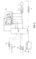
- Figure 1 shows a system comprising an embodiment of a device according to the invention and two modules connected to the device.
- the device can be for example a mobile terminal of a first user, and the modules can be mobile terminals of other users.
- the device comprises a disk drive 1 for rotating a rotating disk memory.
- the disk drive 1 is controlled by servo drivers 2, arm drivers 3 and R/W (read/write) drivers 4.
- the servo drivers 2 control the rotation speed of the disk drive 1, while the arm drivers control read/write heads used for reading data from and writing data to a rotating disk memory.
- the R/W drivers 4 control the actual reading of data from a disk memory and writing data to a disk memory.
- Servo drivers 2, arm drivers 3 and R/W drivers 4 are further connected to system and EM chip or chips 5.
- the operation mode of the connection between the servo drivers 2 and the system and EM chip 5 can be "sleep", "idle”, “seek”, or "rotating".
- the operation mode of the connection between the arm drivers 3 and the system and EM chip 5 can be “sleep”, “idle” or “seeking”.
- the operation mode of the connection between the R/W drivers 4 and the system and EM chip 5 can be “sleep”, “idle” or "R/W”.
- the system and EM chip 5 comprises an energy management (EM) part 6, a microcontroller unit (MCU) 7, a random access memory (RAM) 8 and a nonvolatile memory (NVM) 9, e.g. a flash memory.
- EM energy management
- MCU microcontroller unit
- RAM random access memory
- NVM nonvolatile memory
- the EM part 6 provides a wireless interface for connecting modules supporting BluetoothTM to the device and a USB interface for connecting modules via USB to the device.
- a BluetoothTM component 10 is connected to the device via a BluetoothTM driver 11 included in the BluetoothTM component 10.
- a second module 12 comprising a USB slot is connected to the device via a USB driver 13 included in the second module 12.
- the operation mode of the connection between the EM part 6 and the BluetoothTM component 10 can be "sleep", “monitor” or "RX/TX" (receiving/transmitting). The same operation modes are available for the connection between the EM part 6 and the USB module 12.
- the MCU 7 constitutes processing means controlling the data flow between a disk memory rotated by the disk drive 1 and modules 10, 12 connected to the system and EM chip 5 via the BluetoothTM interface or the USB interface.
- the system and EM chip 5 is moreover connected to a non-volatile buffer 14, which is depicted in figure 1 with dotted lines. Also the connection of the buffer 14 to the system and EM chip 5 is depicted with a dotted line. The dotted lines indicate that the buffer 14 is either extremely small or even missing.
- the operation mode of the connection between the system and EM chip 5 and the buffer 14, if present, can be "sleep" or "ready".
- the system and EM chip 5 is connected for their power supply to a battery 15.
- the operation mode of this connection can be “off”, “sleep” or “full power”.
- the battery 15 can be removable or fixed to the device.
- the battery 15 can be connected to an external charger 16 for recharging the battery 15.
- the operation mode of the connection between the battery 15 and the charger 16 can thus be either “off” or “charging”.
- the device is a mobile terminal as suggested above, additional components of the mobile terminal preferably connect to the systems and EM chips 5 of the device for enabling communications within the mobile terminal. Such a connectivity is not required, in case the device is a stand-alone device provided exclusively for an access to the disk drive 1.
- Figures 2 and 3 relate to the operation of a device comprising multiple interfaces. It will be assumed in the following that this device corresponds to the embodiment of figure 1.
- Figure 2 illustrates the reading of data from a disk memory and figure 3 the writing of data into a disk memory.
- the depicted components and connections are identical in figures 2 and 3. However, different inactive or waiting connections are indicated in both figures with different dotted lines.
- the device comprises a BluetoothTM interface with a receiving unit BT RX 21 and a transmitting unit BT RX 22 and moreover a wired USB interface with a receiving unit USB RX 24 and a transmitting unit USB TX 25. Both interfaces are provided by the EM part 6 of the system and EM chip 5 in figure 1.
- the different receiving and transmitting units 21, 24 and 22, 25 are connected to the MCU 7 of the system and EM chip 5 of figure 1.
- the MCU 7 is used for controlling the traffic between a disk memory and the different interfaces.
- a non-volatile memory 26 constituting a file system is equally connected to the MCU 7.
- the memory 36 can be part of the RAM 8 or the NVM 9 in figure 1 and comprises a file system.
- the file system includes a file system table which constitutes basically a file allocation table (FAT) which enables the device to communicate with the disk drive 1.
- FAT file allocation table
- An output of the MCU 7 is connected to a queue 23. Outputs of the queue 23 are connected to the MCU 7 and to servo and arm drivers 2, 3 controlling the disk drive 1. The disk memory rotated by the disk drive 1 is further connected via an R/W driver 4 to the MCU 7.
- the-maximum bandwidth is reserved for the data-transmitting route to one module, while the other modules are allowed to use only enough bandwidth to transmit read/write commands. This is one of the key factors causing an overhead in the transmissions via the air interface. Since the overhead may not be exactly constant, it may further be necessary to be able to vary. the rotation speed a little bit also for a given interface.
- the device is a mobile phone as suggested above, additional components of the mobile phone may be connected to the system and EM chips 5 of figure 1 for required communications specifically via the file system 26.
- the MCU checks with the file system table 26, from which place in the disk memory requested data has to be read, or to which place in the disk memory data provided by a module should be written.
- information is associated to each read/write command received from connected modules.
- the information comprises an indication of the type of the respectively used interface, an identification of the respective module in multiuser protocols, an R/W flag, an indication of where to start reading or writing and, optionally, an indication of where to stop reading or writing in the disk memory.
- the R/W flag indicates whether the command is a read command, identified in the figure by an "R”, or a write command, identified in the figure by a "W". Since only one module at a time can be connected to the device via the USB interface, an identification of such a module is not required.
- This information is provided by the MCU 7 according to commands received via one of the interfaces and according to the information retrieved from the file system table 26.
- the respective information. that was first provided to the queue 23 is also first retrieved from the queue 23.
- the currently retrieved information indicates that the concerned interface is a BluetoothTM interface "BT", that the information relates to a module with an identification number "2", and that data is to be read “R” from a disk memory from place "AA00" to place “AAFF”.
- the retrieved indication of the type of the interface and the identification of the module is transmitted to the MCU 7.
- the indication of the type of the interface is also provided together with the R/W flag and the start and stop information to the servo and arm drivers 2, 3.
- the servo drivers 2 translate the received indication of the type of the concerned interface to an associated rotation speed, i.e. to a rotation speed matched to the data rate supported by the BluetoothTM interface. This speed is lower than the rotation speed associated to the USB interface.
- the servo driver 2 may comprise a hard-coded rotation profile defining corresponding relations.
- the servo and arm drivers 2, 3 control the rotation speed of the disk drive 1 and the position of the read/write heads in accordance with the determined rotation speed.
- the R/W driver 4 controls a reading of data with a corresponding data rate from place "AA00" to place "AAFF" from a disk memory rotated by the disk drive 1 and provides the read data to the MCU 7.
- the MCU 7 With the indication of the concerned type of interface and of the concerned module, the MCU 7 is able to correctly initiate a transmission of the received data stream to module 2 via the transmission unit BT TX 22 of the BluetoothTM interface. Since the data rate with which the data is received from the disk memory corresponds basically to the data rate supported by the BluetoothTM interface, a further storing of the read data is not required.
- the next set of information is retrieved from the queue 23.
- This information indicates that the concerned interface is again a BluetoothTM interface "BT" and that the information relates again to a module with an identification number "2". In this case, however, data that will be provided by module 2 is to be written "W" into the disk memory beginning at place "BBBB”.
- the indication of the type of the interface and the identification of the module is transmitted again to the MCU 7. Further, the indication of the type of the interface is provided together with the R/W flag and the start information to the servo and drivers 2, 3.
- the servo drivers 2 translate the received indication of the type of the concerned interface again to an associated rotation speed, as described with reference to figure 2.
- the MCU 7 receives data from module 2 via the BT RX 21 in accordance with the information received from the queue 23 and provides the data to the R/W driver 4.
- the servo and arm drivers 2, 3 control meanwhile the disk drive 1 in accordance with the determined rotation speed.
- the R/W driver 4 controls a writing of the received data into a disk memory rotated by the disk drive 1 beginning at place "BBBB" with a data rate corresponding to the rotation speed set by the servo driver 2.
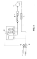
- FIG 4 shows logical flows in a stand-alone device which comprises only a BluetoothTM interface and which is designed in a particularly simple way. It will be assumed in the following that this device corresponds basically to the embodiment of figure 1, but does not comprise a USB interface.
- the BluetoothTM interface includes a receiving unit BT RX 41 and a transmitting unit BT TX 42. Via this interface, one or more BluetoothTM modules maybe connected to the device.
- the receiving unit 41 is connected to the input of a queue 43.
- the queue 43 may be contained for example in the RAM 8 of the device of figure 1.
- the output of the queue 43 is connected to the servo and arm drivers 2, 3 of figure 1.
- the servo and arm drivers 2, 3 are connected as in figure 1 to the disk drive 1 of the device.
- the disk drive 1 is equally connected to an R/W driver 4, as in figure 1.
- the output of the queue 43 is further connected together with the R/W driver 4 to the transmitting unit 42.
- the information in the queue 43 comprises an identification of the respective module providing such a command, e.g. the user ID.
- a specific identification is only depicted for the first two entries in the queue, for the other three entries the identification is represented by a respective dot.
- the information further comprises an R/W flag for indicating whether the command is a read command "R" or a write command "W".
- the information comprises as well an indication of where to start and stop reading from the disk memory.
- the information comprises instead an indication of where to start and stop writing into the disk memory.
- the maximum bandwidth is reserved for the data-transmitting route to one module, while the other modules are allowed to use only enough bandwidth to transmit read/write commands.
- the respective information that was first provided to the queue 43 is also first retrieved from the queue 43.
- the currently retrieved information indicates that it relates to "module 2", and that information is to be read “R” from place “AA00” to place “AAFF” of a disk memory.
- the identification of the module is transmitted to the transmitting unit 42, while the R/W flag and the start and stop information is provided to the servo and arm drivers 2, 3, which controls the rotation speed of the disk drive 1 and the position of the read/write heads.
- the rotation speed of the disk drive 1 is set more specifically such that the resulting effective data rate for reading data from or writing data to the rotating disk memory is matched to the data rate supported by the BluetoothTM interface.
- the required rotation speed may be indicated e.g.
- the data rate required for the BluetoothTM interface is known and fixed, it may be stored for instance in the hardware (ASIC) of the device or in the NVM 9 of the system and EM chips 5 in figure 1.
- the R/W driver 4 controls a reading of data from place "AA00" to place “AAFF” from the rotated disk memory with a corresponding data rate and provides it to the transmitting unit 42. With the indication of the concerned module received directly from the queue 43, the transmitting unit 42 is able to transmit the received data stream correctly to this module 2.
- the device employed for the operations described with reference to figure 4 can be a particularly simple device. All information required for a data transfer is comprised in the BluetoothTM modules connecting to the device. The connected modules know in particular the contents of the disk memory and its structure. The device does not even have to comprise the MCU 7 depicted in figure 1. This approach thus minimizes the required components and the complexity of the device according to the invention.
- the rotation speed of the disk drive 1 is always set such that-the effective data rate for reading data from or writing data to a rotating disk memory is matched to the data rate supported by the currently employed interface.
- the maximum data rate B in bit/s on the air interface is known.
- the maximum data rate of a disk memory is much higher, but for a wireless transmission as for BluetoothTM, its effective data rate BD is set according to the invention close to B. More exactly, it is set to k*B, where k is slightly larger than 1 to accommodate overhead in the BluetoothTM interface. It is to be noted that k will be larger for one-to-many protocols than for one-to-one protocols, since the multiuser protocol needs more overheads.
- the overhead value k may not be exactly constant even for a given interface. It may vary for example with the number of attached modules in a BluetoothTM-based system. If possible, this should be avoided in the air interface by always using the smallest bandwidth for data transmission, even if the overhead is not needed.
- k could be recalculated for example once a second. If the value of k has changed appreciably, then the rotation speed can be changed accordingly. However, by default such changes should be avoided, since acceleration and deceleration of the disk require the maximum amounts of energy.
- the value of k can also be set to the average expected value, but this requires a larger buffer, since at times the HDD may transmit more bits than the air interface can transmit.
- the data rate of the air interface is B bit/s
Landscapes
- Signal Processing For Digital Recording And Reproducing (AREA)
Abstract
Description
- The invention relates to a device comprising a disk drive for rotating a disk memory and at least one interface enabling a data flow between a disk memory rotated by the disk drive and at least one other module. The invention relates equally to a method for setting the rotation speed of a disk drive of such a device.
- It is well known from the state of the art that rotating disk based memories like hard disk drives (HDD) or optical disks are employed for storing data. Data can be written into such a disk memory or read from such a disk memory while it is rotated by a disk drive of some device. Data that is to be stored in the rotating disk memory can be provided by some module internal or external to the device. Equally, a module internal or external to the device might require data that is stored in the rotating disk memory. Such modules can be connected to the rotating disk memory via an interface enabling a corresponding data flow.
- In devices comprising different interfaces to a disk memory rotated by a disk drive, which interfaces support different data rates, a buffer is required, in order to be able to store data read from the rotating disk memory with a data rate exceeding the data rate supported by the slower interfaces. This buffer is usually realized as a non-volatile buffer.
- In particular with handheld devices which are powered by small batteries, it is necessary to keep the power consumption as low as possible in order to enable a long operation without the need to exchange or reload the battery. It is also desirable to keep the number and/or size of the components of the device as small as possible, in order to be able to provide a small and light device for a maximum comfort for the user of the device and in order to minimize the costs of the device.
- It is primarily an object of the invention to enable a low power consumption, while avoiding disadvantageous effects on the operation of the device. It is further an object of the invention to reduce the number or size of the components of the device. It is also an object of the invention to improve the comfort in using a device comprising a disk drive for rotating a disk memory.
- This object is reached on the one hand with a device comprising a disk drive for rotating a disk memory and with at least one interface enabling a data flow between a disk memory rotated by the disk drive and at least one other module. The proposed device further comprises means for setting the rotation speed of the disk drive based on an indication of the data rate supported by an interface of the device, which interface is currently to be employed for enabling a data flow between the rotating disk memory and at least one other module.
- On the other hand, the object of the invention is reached with a method for setting the rotation speed of a disk drive of such a device. The proposed method comprises as a first step determining a rotation speed for the disk drive based on an indication of the data rate supported by an interface of the device, which interface is currently to be employed for enabling a data flow between the disk memory and at least one other module. In a second step of the proposed method, the rotation speed of the disk drive is then set to the determined rotation speed.
- The invention proceeds from the consideration that the effective data rate of the data read from or written to a rotating disk memory relates to the rotation speed of the disk memory, and that therefore, it is possible to achieve an optimal co-operation between a rotating disk memory and an interface, if the respective rotation speed is adapted to the capabilities of the employed interface. The effective data rate of the disk memory can be adjusted in particular such that it is always close to the effective data rate of the currently employed interface.
- It is an advantage of the invention that it results in a lower power consumption while employing interfaces supporting only a low data rate. This leads to a longer battery use time. At the same time, it is ensured that interfaces supporting a high data rate, e.g. wired interfaces, can be used for data transmissions with this high data rate.
- It is moreover an advantage of the invention that it minimizes the need for buffer space, since with an adjusted rotation speed, it is no longer necessary to buffer data read from the disk memory for slow interfaces. The invention therefore eliminates the need for a non-volatile buffer. This allows to remove one component from the system and thus to reduce cost and size of the device. A volatile cache will be sufficient for handling irregularities in the data traffic.
- Finally, it is an advantage of the invention that it provides a new freedom in the design of signal-processing algorithms, where the same software and hardware can be employed in different embodiments of a communication device according to the invention. This leads to further savings in cost, size and complexity. For example, the same software and/or hardware for controlling the disk memory can be used for devices comprising only a slow interface, for devices comprising only a fast interface and for devices comprising slow and fast interfaces, since in each case the rotation speed is adjusted automatically to the optimum value for the respectively used interface. In case the device has both, a slow and a fast interface, the disk memory will be operated at two speeds, a high speed resulting in a high data rate for the fast interface, in order to improve the usability, and a low speed resulting in a low data rate for the slow interface, in order to decrease the power consumption.
- A device according to the invention comprising only a single interface can be considered to constitute a special case of the general embodiment with multiple interfaces. A device with a single interface has the advantage that its hardware can be realized in a particularly simple way, and that the required overhead of transmissions can be much smaller. Further, it is possible to optimize the energy much better, since the speed of the drive does not have to be changed.
- Preferred embodiments of the invention become apparent from the subclaims.
- The disk memory that is rotated by the disk drive of the device can be for example a hard disk drive or an optical disk.
- At least one interface of the device can be a wired interface or a wireless interface. A wired interface, e.g. a USB (Universal Serial Bus) interface, will usually be faster than a wireless interface, like a Bluetooth™ interface. It is to be noted that USB and Bluetooth™ are only exemplary interfaces. The invention can equally be employed with any other interface.
- The indication of the data rate supported by the respective interface can be provided to the means for adjusting the rotation speed, e.g. by an indication of the type of the interface for which the supported data rate is known. The means for adapting the rotation speed of the disk memory may comprise in particular a servo driver controlling the rotation speed of the disk drive.
- In a preferred embodiment of the invention, the rotation speed of the disk memory is varied by a servo driver according to a rotation profile which is either defined by software or hard-coded into the servo driver. The rotation profile associates a respective indication of the data rate supported by an interface to a respective rotation speed to be employed for a disk memory. In case a software external to the servo driver is employed, the software forwards the determined rotation speed to the servo driver for adjusting the rotation speed of the disk drive.
- In one special embodiment of the invention, all possible applications for which a data flow may be desired are divided into a plurality of classes, based on the data-rate requirements of the respective application. The class of the respective application is then taken into account in addition, when determining the rotation speed. Preferably, the applications are divided into 2-3 classes, and the disk speed is set accordingly to one of 2-3 different values depending on the class of the particular running application. This embodiment of the invention can be implemented in a variety of ways. In a first possible implementation, the required class information is included as an extra field in a file allocation table. In a second possible implementation, a mirror copy of a file allocation table is created in a non-volatile memory, which memory holds the normal file allocation table data in addition to a field associating the files to a respective class. The mirror file allocation table is then used to access the data. The mirror file allocation table and the actual file allocation table have to be kept synchronized. In a third possible implementation, the required class information is derived from file attributes, when the system receives the command to access a file, e.g. the file extension.
- The other module or modules connected to the disk memory via an interface can either be comprised in a device according to the invention, or be external to such a device.
- The device and the method according to the invention may support a one-to-one connection, i.e. a connection between the device and one other module, or a one-to-many connection, i.e. a connection between the device and several other modules. It is an advantage of a device and a method realizing a one-to-one connection that they will be significantly simpler.
- The device can further be a stand-alone system or part of a larger system, like a mobile phone. In the latter case, a connection possibility for other components of the system to the device will usually be required, in order to enable communications within the system.
- The most simple realization of the invention is achieved with a stand-alone device comprising only a single interface which is employed exclusively for one-to-one connections.
- In a preferred embodiment of the invention, a queue control algorithm is used to optimize the usage of the disk memory. For example, it would be disadvantageous to switch rotation speeds quickly, since this requires much energy. Therefore, it is proposed to employ a queue control algorithm for grouping those operations together which require the same speed. This should be balanced against the user wait times, in which such a grouping can result. Another approach could be to arrange data transfers concerning the same module in a consecutive order in the queue.
- In devices comprising only a single interface, there is no need for queue-control algorithms to optimize the energy, since the energy is always the same. However, even in this case there could be a queue control to handle requests that have different urgencies.
- The queue control algorithm can also be simplified for a device comprising a plurality of interfaces, in case there is a restriction that only one interface can operate at a time. Such a restriction would avoid the need to group transmissions requiring the same speed together. The most flexible queuing algorithm has thus three modes, a BT-only mode, an USB-only mode and a joint BT and USB mode. All the other software can be shared in the three modes.
- The device according to the invention can be any device that enables the use of a rotating disk memory. The invention is of a particular advantage for handheld devices like mobile terminals.
- Other objects and features of the present invention will become apparent from the following detailed description considered in conjunction with the accompanying drawings, wherein:
- Fig. 1
- schematically shows the physical architecture of a system comprising an embodiment of the device according to the invention;
- Fig. 2
- illustrates logical flows for reading of data from a disk memory in an embodiment of the device according to the invention comprising multiple interfaces;
- Fig. 3
- illustrates logical flows for writing data to a disk memory in an embodiment of the device according to the invention comprising multiple interfaces; and
- Fig. 4
- illustrates the logical flows in an embodiment of the device according to the invention comprising a single interface.
- Figure 1 shows a system comprising an embodiment of a device according to the invention and two modules connected to the device. The device can be for example a mobile terminal of a first user, and the modules can be mobile terminals of other users.
- The device comprises a
disk drive 1 for rotating a rotating disk memory. Thedisk drive 1 is controlled byservo drivers 2,arm drivers 3 and R/W (read/write)drivers 4. Theservo drivers 2 control the rotation speed of thedisk drive 1, while the arm drivers control read/write heads used for reading data from and writing data to a rotating disk memory. The R/W drivers 4 control the actual reading of data from a disk memory and writing data to a disk memory.Servo drivers 2,arm drivers 3 and R/W drivers 4 are further connected to system and EM chip orchips 5. The operation mode of the connection between theservo drivers 2 and the system andEM chip 5 can be "sleep", "idle", "seek", or "rotating". The operation mode of the connection between thearm drivers 3 and the system andEM chip 5 can be "sleep", "idle" or "seeking". The operation mode of the connection between the R/W drivers 4 and the system andEM chip 5 can be "sleep", "idle" or "R/W". - The system and
EM chip 5 comprises an energy management (EM)part 6, a microcontroller unit (MCU) 7, a random access memory (RAM) 8 and a nonvolatile memory (NVM) 9, e.g. a flash memory. - The
EM part 6 provides a wireless interface for connecting modules supporting Bluetooth™ to the device and a USB interface for connecting modules via USB to the device. In figure 1, aBluetooth™ component 10 is connected to the device via aBluetooth™ driver 11 included in theBluetooth™ component 10. Further, asecond module 12 comprising a USB slot is connected to the device via aUSB driver 13 included in thesecond module 12. The operation mode of the connection between theEM part 6 and theBluetooth™ component 10 can be "sleep", "monitor" or "RX/TX" (receiving/transmitting). The same operation modes are available for the connection between theEM part 6 and theUSB module 12. - The
MCU 7 constitutes processing means controlling the data flow between a disk memory rotated by thedisk drive 1 andmodules EM chip 5 via the Bluetooth™ interface or the USB interface. - The system and
EM chip 5 is moreover connected to anon-volatile buffer 14, which is depicted in figure 1 with dotted lines. Also the connection of thebuffer 14 to the system andEM chip 5 is depicted with a dotted line. The dotted lines indicate that thebuffer 14 is either extremely small or even missing. The operation mode of the connection between the system andEM chip 5 and thebuffer 14, if present, can be "sleep" or "ready". - Finally, the system and
EM chip 5 is connected for their power supply to abattery 15. The operation mode of this connection can be "off", "sleep" or "full power". Thebattery 15 can be removable or fixed to the device. Thebattery 15 can be connected to anexternal charger 16 for recharging thebattery 15. The operation mode of the connection between thebattery 15 and thecharger 16 can thus be either "off" or "charging". - In case the device is a mobile terminal as suggested above, additional components of the mobile terminal preferably connect to the systems and
EM chips 5 of the device for enabling communications within the mobile terminal. Such a connectivity is not required, in case the device is a stand-alone device provided exclusively for an access to thedisk drive 1. - Logical flows occurring during the operation in an embodiment of the device according to the invention are illustrated in more detail in figures 2 to 4.
- Figures 2 and 3 relate to the operation of a device comprising multiple interfaces. It will be assumed in the following that this device corresponds to the embodiment of figure 1. Figure 2 illustrates the reading of data from a disk memory and figure 3 the writing of data into a disk memory. The depicted components and connections are identical in figures 2 and 3. However, different inactive or waiting connections are indicated in both figures with different dotted lines.
- In the embodiment of figures 2 and 3, the device comprises a Bluetooth™ interface with a receiving
unit BT RX 21 and a transmittingunit BT RX 22 and moreover a wired USB interface with a receivingunit USB RX 24 and a transmittingunit USB TX 25. Both interfaces are provided by theEM part 6 of the system andEM chip 5 in figure 1. - The different receiving and transmitting
units MCU 7 of the system andEM chip 5 of figure 1. TheMCU 7 is used for controlling the traffic between a disk memory and the different interfaces. Anon-volatile memory 26 constituting a file system is equally connected to theMCU 7. The memory 36 can be part of theRAM 8 or theNVM 9 in figure 1 and comprises a file system. The file system includes a file system table which constitutes basically a file allocation table (FAT) which enables the device to communicate with thedisk drive 1. - An output of the
MCU 7 is connected to aqueue 23. Outputs of thequeue 23 are connected to theMCU 7 and to servo andarm drivers disk drive 1. The disk memory rotated by thedisk drive 1 is further connected via an R/W driver 4 to theMCU 7. - Queuing is necessary, since the wireless interface may be too slow to accommodate all data requests immediately. In this embodiment, the-maximum bandwidth is reserved for the data-transmitting route to one module, while the other modules are allowed to use only enough bandwidth to transmit read/write commands. This is one of the key factors causing an overhead in the transmissions via the air interface. Since the overhead may not be exactly constant, it may further be necessary to be able to vary. the rotation speed a little bit also for a given interface.
- In case the device is a mobile phone as suggested above, additional components of the mobile phone may be connected to the system and
EM chips 5 of figure 1 for required communications specifically via thefile system 26. - When read/write commands are received from modules via the receiving
unit - In the
queue 23, information is associated to each read/write command received from connected modules. The information comprises an indication of the type of the respectively used interface, an identification of the respective module in multiuser protocols, an R/W flag, an indication of where to start reading or writing and, optionally, an indication of where to stop reading or writing in the disk memory. The R/W flag indicates whether the command is a read command, identified in the figure by an "R", or a write command, identified in the figure by a "W". Since only one module at a time can be connected to the device via the USB interface, an identification of such a module is not required. This information is provided by theMCU 7 according to commands received via one of the interfaces and according to the information retrieved from the file system table 26. - In the presented embodiment, the respective information. that was first provided to the
queue 23 is also first retrieved from thequeue 23. - In figure 2, the currently retrieved information indicates that the concerned interface is a Bluetooth™ interface "BT", that the information relates to a module with an identification number "2", and that data is to be read "R" from a disk memory from place "AA00" to place "AAFF". The retrieved indication of the type of the interface and the identification of the module is transmitted to the
MCU 7. The indication of the type of the interface is also provided together with the R/W flag and the start and stop information to the servo andarm drivers servo drivers 2 translate the received indication of the type of the concerned interface to an associated rotation speed, i.e. to a rotation speed matched to the data rate supported by the Bluetooth™ interface. This speed is lower than the rotation speed associated to the USB interface. In order to be able to translate an indication of the type of an interface to a specific rotation speed, theservo driver 2 may comprise a hard-coded rotation profile defining corresponding relations. - The servo and
arm drivers disk drive 1 and the position of the read/write heads in accordance with the determined rotation speed.. The R/W driver 4 controls a reading of data with a corresponding data rate from place "AA00" to place "AAFF" from a disk memory rotated by thedisk drive 1 and provides the read data to theMCU 7. With the indication of the concerned type of interface and of the concerned module, theMCU 7 is able to correctly initiate a transmission of the received data stream tomodule 2 via the transmissionunit BT TX 22 of the Bluetooth™ interface. Since the data rate with which the data is received from the disk memory corresponds basically to the data rate supported by the Bluetooth™ interface, a further storing of the read data is not required. - In figure 3, the next set of information is retrieved from the
queue 23. This information indicates that the concerned interface is again a Bluetooth™ interface "BT" and that the information relates again to a module with an identification number "2". In this case, however, data that will be provided bymodule 2 is to be written "W" into the disk memory beginning at place "BBBB". The indication of the type of the interface and the identification of the module is transmitted again to theMCU 7. Further, the indication of the type of the interface is provided together with the R/W flag and the start information to the servo anddrivers servo drivers 2 translate the received indication of the type of the concerned interface again to an associated rotation speed, as described with reference to figure 2. - The
MCU 7 receives data frommodule 2 via theBT RX 21 in accordance with the information received from thequeue 23 and provides the data to the R/W driver 4. - The servo and
arm drivers disk drive 1 in accordance with the determined rotation speed. - The R/
W driver 4 controls a writing of the received data into a disk memory rotated by thedisk drive 1 beginning at place "BBBB" with a data rate corresponding to the rotation speed set by theservo driver 2. - Figure 4 shows logical flows in a stand-alone device which comprises only a Bluetooth™ interface and which is designed in a particularly simple way. It will be assumed in the following that this device corresponds basically to the embodiment of figure 1, but does not comprise a USB interface. The Bluetooth™ interface includes a receiving
unit BT RX 41 and a transmittingunit BT TX 42. Via this interface, one or more Bluetooth™ modules maybe connected to the device. The receivingunit 41 is connected to the input of aqueue 43. Thequeue 43 may be contained for example in theRAM 8 of the device of figure 1. The output of thequeue 43 is connected to the servo andarm drivers arm drivers disk drive 1 of the device. Thedisk drive 1 is equally connected to an R/W driver 4, as in figure 1. The output of thequeue 43 is further connected together with the R/W driver 4 to the transmittingunit 42. - In the
queue 43, information is stored in accordance with the read/write commands received from connected modules via the receivingunit 41. First, the device requires a unique identification for each module sending read/write commands. Therefore, the information in thequeue 43 comprises an identification of the respective module providing such a command, e.g. the user ID. In figure 4, a specific identification is only depicted for the first two entries in the queue, for the other three entries the identification is represented by a respective dot. The information further comprises an R/W flag for indicating whether the command is a read command "R" or a write command "W". In case of a read command, the information comprises as well an indication of where to start and stop reading from the disk memory. In case of a write command, the information comprises instead an indication of where to start and stop writing into the disk memory. - As in the embodiment of figures 2 and 3, the maximum bandwidth is reserved for the data-transmitting route to one module, while the other modules are allowed to use only enough bandwidth to transmit read/write commands.
- The respective information that was first provided to the
queue 43 is also first retrieved from thequeue 43. In the presented example, the currently retrieved information indicates that it relates to "module 2", and that information is to be read "R" from place "AA00" to place "AAFF" of a disk memory. The identification of the module is transmitted to the transmittingunit 42, while the R/W flag and the start and stop information is provided to the servo andarm drivers disk drive 1 and the position of the read/write heads. The rotation speed of thedisk drive 1 is set more specifically such that the resulting effective data rate for reading data from or writing data to the rotating disk memory is matched to the data rate supported by the Bluetooth™ interface. The required rotation speed may be indicated e.g. by some software implemented in the device to the servo andarm drivers NVM 9 of the system andEM chips 5 in figure 1. - The R/
W driver 4 controls a reading of data from place "AA00" to place "AAFF" from the rotated disk memory with a corresponding data rate and provides it to the transmittingunit 42. With the indication of the concerned module received directly from thequeue 43, the transmittingunit 42 is able to transmit the received data stream correctly to thismodule 2. - The device employed for the operations described with reference to figure 4 can be a particularly simple device. All information required for a data transfer is comprised in the Bluetooth™ modules connecting to the device. The connected modules know in particular the contents of the disk memory and its structure. The device does not even have to comprise the
MCU 7 depicted in figure 1. This approach thus minimizes the required components and the complexity of the device according to the invention. - As mentioned above, the rotation speed of the
disk drive 1 is always set such that-the effective data rate for reading data from or writing data to a rotating disk memory is matched to the data rate supported by the currently employed interface. The maximum data rate B in bit/s on the air interface is known. The maximum data rate of a disk memory is much higher, but for a wireless transmission as for Bluetooth™, its effective data rate BD is set according to the invention close to B. More exactly, it is set to k*B, where k is slightly larger than 1 to accommodate overhead in the Bluetooth™ interface. It is to be noted that k will be larger for one-to-many protocols than for one-to-one protocols, since the multiuser protocol needs more overheads. - Note that in some cases, the overhead value k may not be exactly constant even for a given interface. It may vary for example with the number of attached modules in a Bluetooth™-based system. If possible, this should be avoided in the air interface by always using the smallest bandwidth for data transmission, even if the overhead is not needed.
- However, even if this is impossible, this results only in small perturbations around the average value of the rotation speed ω. The simplest way to handle this problem is to recalculate k at regular intervals with a frequency much lower than the bandwidth frequency. In the case of Bluetooth™, k could be recalculated for example once a second. If the value of k has changed appreciably, then the rotation speed can be changed accordingly. However, by default such changes should be avoided, since acceleration and deceleration of the disk require the maximum amounts of energy. In general, it is preferable to set k to the minimum expected value, i.e. the HDD transmits data at a rate that is smaller than the maximum rate of the air interface. Filler bits may be needed in this case to achieve the correct air transmission speed. Although this will result in sub-optimal speeds in the air interface, the power savings are considerable. The value of k can also be set to the average expected value, but this requires a larger buffer, since at times the HDD may transmit more bits than the air interface can transmit.
- It will now be shown that such an approach minimizes the power consumption of the system.
- For the disk drive, the data rate is given by s = σωr, where σ is the number of bits per millimeter on the surface of the disk memory, where ω is the rotation speed of the disk memory, and where r is the radius at which the read head is located. r is assumed to be constant in the following calculations.
- The power consumption is given in general by P = Σaiωk ( i ), where i is an index, running, in theory, from 1 to infinity, where ai is a coefficient assigned to a respective index i, and where k(i) approximates the energy function. k(i) is typically, but not always, equal to i. More specifically, this approximation is usually valid for a close to steady state operation, although it may not be valid for the spin-up and spin-down phases, in which several non-linearities occur. If k(i)=i, then k(i) is the Taylor series that approximates the energy function.
- The length L of a data file can be put into relation to the data rate s and the reading time T, and thus to the rotation speed ω and the reading time T, by the equations L = sT = σωrT. The energy required for this data file is thensince P is not dependent on time. While usually k(i) is equal to i, some'of the k(i) values could also be fractional. It is for instance possible that for some specific system, the energy is best approximated by an equation like E=2.1*ω2 + 0.7*ω0.7. In order to find the exact ω-energy profile of a system, it is necessary to use empirical estimates or calculations.

- In a typical case, one component of the series dominates P (usually i=k (i)=2), leading to the approximation E1/E2 ≈ ω1/ω2. The power consumption scales as the square, but the total expended energy scales according to the preceding relation, since the slower read mode also uses more time. Thus, it becomes apparent that decreasing the rotation speed greatly reduces the energy consumption of the system.
- Strictly speaking, it is necessary for E(ω) to be monotonously increasing, which is the case for any normal system. There may be theoretical systems that have some type of gear system, in which the energy might actually locally decrease over some small range of ω. However, any such system can be described by the above equation for the energy, and does not change the fundamental idea. In theory, if the ω for a given B happens to fall within this falling range, it would be possible to optimize the energy by increasing_ω slightly so that it reaches the local minimum
ω . However, this means that the disk data rate becomes larger than the air data rate, which requires the use of a larger buffer. The required size of the buffer can in theory be estimated from S= <OT>*[ω -ω], where the <OT> is a statistical estimate of the length of time that would be spent in this mode (overshoot time). This time depends on expected clip size distributions etc. In practice, such cases are so rare that there is no point in adding this complexity and extra buffering to the system. - The equation presented for the determination of energy E covers all cases, except those where there is hysteresis. Even in the case of hysteresis, it is possible to use the presented equation by writing ai in the sum as a function of time, and possibly also of ω, i.e. as ai=ai (ω,t). In this case, it is not possible to determine analytically how much power is saved by the proposed method. Nor is it easily possible to determine whether there are local minima of ω as mentioned above. However, even when this is possible, the task of estimating the buffer size becomes essentially impossible analytically. Thus, hysteresis will have an effect on the amount of power savings, but even in this case the simple algorithm described above gives the best average power savings for the least complexity and the smallest system (buffer) size.
- As mentioned above, the data rate of the air interface is B bit/s, and the bit rate of the disk memory BD is set for a transmission via the air interface to BD=k*B. The rotation speed ω required' for achieving this data rate BD can be calculated according to the above equations to:
- It is to be noted that the described embodiments constitute selected ones of a variety of possible embodiments of the invention.
Claims (14)
- Device comprisinga disk drive (1) for rotating a disk memory;at least one interface enabling a data flow between a disk memory rotated by said disk drive (1) and at least one other module (10,12); andmeans (2) for setting the rotation speed of said disk drive (1) based on an indication of the data rate supported by an interface of said device, which interface is currently to be employed for 'enabling a data flow between said rotating disk memory and at least one other module (10,12).
- Device according to claim 1, wherein said indication of a supported data rate is given by an indication of the type of said interface which is currently to be employed for enabling a data flow between said rotating disk memory and at least one other module (10,12).
- Device according to one of the preceding claims, wherein said means for setting the rotation speed of said disk drive (1) comprise a servo driver (2) controlling the rotation speed of said disk drive (1), and wherein said means for setting the rotation speed of said disk drive (1) further comprise software associating a respective indication of a supported data rate to a respective rotation speed of said disk drive (1), which associated rotation speed is employed by said servo driver (2) for controlling said disk drive (1).
- Device according to one of the preceding claims,
wherein said means for setting the rotation speed of
said disk drive (1) comprise a servo driver (2) controlling the rotation speed of said disk drive (1), wherein said servo driver (2) comprises a hard-coded rotation profile translating received indications of a supported data rate to a respective rotation speed of said disk driver, and wherein a rotation speed determined based on said hard-coded rotation profile is employed by said servo driver (2) for controlling said disk drive (1). - Device according to one of the preceding claims, wherein said means (2) for setting the rotation speed of said disk drive (1) set said rotation speed based in addition on the class of the application for which said data flow is required, each possible application being associated to one of at least two different classes.
- Device according to one of the preceding claims, wherein said at least one interface is an interface enabling a connection of one other module at a time, or an interface enabling a connection of a plurality of other modules at a time.
- Device according to one of the preceding claims, wherein said at least one interface is a wired and/or a wireless interface.
- Device according to one of the preceding claims, wherein said at least one other module is comprised in said device.
- Device according to one of the preceding claims, wherein said at least one other module is external to said device.
- Device according to one of the preceding claims, wherein said disk memory is a hard disk drive or an optical disk.
- Device according to one of the preceding claims, wherein said device is a handheld terminal.
- Method for setting the rotation speed of a disk drive(1) of a device, which disk drive (1) rotates a disk memory, wherein at least one interface of said device enables a data flow between said rotating disk memory and at least one other module (10,12), said method comprising:determining a rotation speed for said disk drive (1) based on an indication of the data rate supported by an interface of said device, which interface is currently to be employed for enabling a data flow between said disk memory and at least one other module (10,12); andsetting the rotation speed of said disk drive (1) to said determined rotation speed.
- Method according to claim 12, wherein said indication of a supported data rate is given by an indication of the type of the respective interface.
- Method according to claim 12 or 13, wherein said rotation speed is determined based in addition on the class of the application for which said data flow is required, each possible application being associated to one of at least two different classes.
Priority Applications (7)
| Application Number | Priority Date | Filing Date | Title |
|---|---|---|---|
| DE60220991T DE60220991T2 (en) | 2002-05-13 | 2002-05-13 | Setting the rotational speed of a rotating disk storage |
| EP02010142A EP1365400B1 (en) | 2002-05-13 | 2002-05-13 | Setting the rotation speed of a rotating disk memory |
| AU2003214586A AU2003214586A1 (en) | 2002-05-13 | 2003-04-15 | Setting the rotation speed of a rotating disk memory |
| CNB038108240A CN100463068C (en) | 2002-05-13 | 2003-04-15 | Device and method for setting the rotational speed of a carousel memory |
| US10/514,085 US7262929B2 (en) | 2002-05-13 | 2003-04-15 | Setting the rotation speed of a rotating disk memory |
| KR1020047018166A KR100971166B1 (en) | 2002-05-13 | 2003-04-15 | Apparatus and method for setting the rotation speed of a rotating disk memory |
| PCT/IB2003/001467 WO2003096335A1 (en) | 2002-05-13 | 2003-04-15 | Setting the rotation speed of a rotating disk memory |
Applications Claiming Priority (1)
| Application Number | Priority Date | Filing Date | Title |
|---|---|---|---|
| EP02010142A EP1365400B1 (en) | 2002-05-13 | 2002-05-13 | Setting the rotation speed of a rotating disk memory |
Publications (2)
| Publication Number | Publication Date |
|---|---|
| EP1365400A1 true EP1365400A1 (en) | 2003-11-26 |
| EP1365400B1 EP1365400B1 (en) | 2007-07-04 |
Family
ID=29286113
Family Applications (1)
| Application Number | Title | Priority Date | Filing Date |
|---|---|---|---|
| EP02010142A Expired - Lifetime EP1365400B1 (en) | 2002-05-13 | 2002-05-13 | Setting the rotation speed of a rotating disk memory |
Country Status (7)
| Country | Link |
|---|---|
| US (1) | US7262929B2 (en) |
| EP (1) | EP1365400B1 (en) |
| KR (1) | KR100971166B1 (en) |
| CN (1) | CN100463068C (en) |
| AU (1) | AU2003214586A1 (en) |
| DE (1) | DE60220991T2 (en) |
| WO (1) | WO2003096335A1 (en) |
Families Citing this family (3)
| Publication number | Priority date | Publication date | Assignee | Title |
|---|---|---|---|---|
| US8369040B2 (en) * | 2009-11-17 | 2013-02-05 | Hitachi, Ltd. | Storage control device and rotation speed control method for storage device |
| JP2016531370A (en) * | 2013-09-09 | 2016-10-06 | シーゲイト テクノロジー エルエルシーSeagate Technology LLC | Mobile data storage device with temperature management |
| JP2024046317A (en) * | 2022-09-22 | 2024-04-03 | 株式会社東芝 | magnetic disk device |
Citations (3)
| Publication number | Priority date | Publication date | Assignee | Title |
|---|---|---|---|---|
| US4943907A (en) * | 1987-05-08 | 1990-07-24 | Colorado Memory Systems, Inc. | Speed controller for recording and playback apparatus |
| US5825572A (en) * | 1994-03-28 | 1998-10-20 | Sony Corporation | Apparatus and method for recording data according to a measured transfer speed |
| EP1168326A2 (en) * | 2000-06-20 | 2002-01-02 | Ricoh Company, Ltd. | Information reproducing method and apparatus |
Family Cites Families (15)
| Publication number | Priority date | Publication date | Assignee | Title |
|---|---|---|---|---|
| JPS60154373A (en) * | 1984-01-23 | 1985-08-14 | Teac Co | Magnetic disk device |
| JPS60177404A (en) * | 1984-02-23 | 1985-09-11 | Toshiba Corp | Disk device |
| JPH09198688A (en) * | 1996-01-19 | 1997-07-31 | Hitachi Ltd | Disc reproducing method and disc reproducing apparatus |
| MY117767A (en) * | 1996-07-10 | 2004-08-30 | Sony Corp | Apparatus and method for reproducing data recorded at a predetermined linear velocity on a disc-like recording medium. |
| JPH11120687A (en) * | 1997-10-15 | 1999-04-30 | Mitsumi Electric Co Ltd | Optical disk drive |
| KR20010004773A (en) * | 1999-06-29 | 2001-01-15 | 구자홍 | Method for controling velocity of reproducing speed on disc player |
| KR100259234B1 (en) * | 1999-11-18 | 2000-06-15 | Kwon Oh Jin | Portable compressed color still image display device |
| JP2001154808A (en) * | 1999-11-30 | 2001-06-08 | Sony Corp | Information processing system, control device, controlled device, and connection state confirmation method |
| US6876606B2 (en) * | 2000-02-07 | 2005-04-05 | Matsushita Electric Industrial Co., Ltd. | Motor control apparatus, disk apparatus and acceleration detection device |
| JP2001256717A (en) * | 2000-03-14 | 2001-09-21 | Matsushita Electric Ind Co Ltd | Disk unit |
| JP3795738B2 (en) * | 2000-09-29 | 2006-07-12 | 富士通株式会社 | Recording medium rotation control method and storage device |
| JP2002222522A (en) * | 2001-01-24 | 2002-08-09 | Matsushita Electric Ind Co Ltd | Information disc recording / reproducing apparatus and vibration detection method for information disc recording / reproducing apparatus |
| KR200230770Y1 (en) * | 2001-02-21 | 2001-07-19 | 주식회사 새로텍 | An external storage device having compatibility to multi-interfaces |
| JP2002343013A (en) * | 2001-05-18 | 2002-11-29 | Sanyo Electric Co Ltd | Disk drive device |
| KR100357377B1 (en) * | 2002-04-08 | 2002-10-19 | (주)그루아이티에스 | Fixed and mobile antenna systems for aquisition, transmission and display of inter-vehicle information |
-
2002
- 2002-05-13 EP EP02010142A patent/EP1365400B1/en not_active Expired - Lifetime
- 2002-05-13 DE DE60220991T patent/DE60220991T2/en not_active Expired - Lifetime
-
2003
- 2003-04-15 WO PCT/IB2003/001467 patent/WO2003096335A1/en not_active Ceased
- 2003-04-15 KR KR1020047018166A patent/KR100971166B1/en not_active Expired - Fee Related
- 2003-04-15 AU AU2003214586A patent/AU2003214586A1/en not_active Abandoned
- 2003-04-15 US US10/514,085 patent/US7262929B2/en not_active Expired - Lifetime
- 2003-04-15 CN CNB038108240A patent/CN100463068C/en not_active Expired - Fee Related
Patent Citations (3)
| Publication number | Priority date | Publication date | Assignee | Title |
|---|---|---|---|---|
| US4943907A (en) * | 1987-05-08 | 1990-07-24 | Colorado Memory Systems, Inc. | Speed controller for recording and playback apparatus |
| US5825572A (en) * | 1994-03-28 | 1998-10-20 | Sony Corporation | Apparatus and method for recording data according to a measured transfer speed |
| EP1168326A2 (en) * | 2000-06-20 | 2002-01-02 | Ricoh Company, Ltd. | Information reproducing method and apparatus |
Also Published As
| Publication number | Publication date |
|---|---|
| WO2003096335A1 (en) | 2003-11-20 |
| US7262929B2 (en) | 2007-08-28 |
| KR100971166B1 (en) | 2010-07-20 |
| KR20040108799A (en) | 2004-12-24 |
| CN100463068C (en) | 2009-02-18 |
| AU2003214586A1 (en) | 2003-11-11 |
| US20050240684A1 (en) | 2005-10-27 |
| CN1653537A (en) | 2005-08-10 |
| DE60220991T2 (en) | 2008-03-06 |
| EP1365400B1 (en) | 2007-07-04 |
| DE60220991D1 (en) | 2007-08-16 |
Similar Documents
| Publication | Publication Date | Title |
|---|---|---|
| US7636809B2 (en) | Adaptive storage system including hard disk drive with flash interface | |
| US7500030B2 (en) | Control of information units in fibre channel communications | |
| US7617359B2 (en) | Adaptive storage system including hard disk drive with flash interface | |
| KR101580658B1 (en) | Solid-state disk with wireless functionality | |
| US6564271B2 (en) | Method and apparatus for automatically transferring I/O blocks between a host system and a host adapter | |
| US7352486B2 (en) | Printer | |
| US8464084B2 (en) | Serial ATA (SATA) power optimization through automatic deeper power state transition | |
| US20020065982A1 (en) | 1394 hard disk sector format selection | |
| US6868478B2 (en) | Method, system, and article of manufacture for optimizing storage utilization | |
| US6311257B1 (en) | Method and system for allocating memory for a command queue | |
| JP4036992B2 (en) | Cache control apparatus and method for dynamically managing data between cache modules | |
| EP1365400B1 (en) | Setting the rotation speed of a rotating disk memory | |
| US8244939B2 (en) | Method and apparatus for dynamically allocating queue depth by initiator | |
| CN108205478B (en) | Intelligent sequential SCSI physical layer power management | |
| US5717949A (en) | System for reading transfer control parameters based on identification codes stored in first and second registers storing destination identification and designated control section identification data | |
| EP1418506A2 (en) | Data storing system and transmission control method | |
| WO1998028679A1 (en) | Data transfer with mirroring | |
| US7143209B2 (en) | Storage control apparatus and control method thereof | |
| KR20040066311A (en) | Apparatus and method for data transmission in dma | |
| CN223679640U (en) | I2C slave controller, slave device and electronic control system | |
| US11126233B2 (en) | Interface bridge circuit capable of reducing heat generation | |
| JP2003099396A (en) | Network interface circuit | |
| JPH0546532A (en) | High speed SCSI host adapter |
Legal Events
| Date | Code | Title | Description |
|---|---|---|---|
| PUAI | Public reference made under article 153(3) epc to a published international application that has entered the european phase |
Free format text: ORIGINAL CODE: 0009012 |
|
| AK | Designated contracting states |
Kind code of ref document: A1 Designated state(s): AT BE CH CY DE DK ES FI FR GB GR IE IT LI LU MC NL PT SE TR |
|
| AX | Request for extension of the european patent |
Extension state: AL LT LV MK RO SI |
|
| 17P | Request for examination filed |
Effective date: 20040206 |
|
| AKX | Designation fees paid |
Designated state(s): DE FI FR GB NL |
|
| 17Q | First examination report despatched |
Effective date: 20050323 |
|
| GRAP | Despatch of communication of intention to grant a patent |
Free format text: ORIGINAL CODE: EPIDOSNIGR1 |
|
| GRAS | Grant fee paid |
Free format text: ORIGINAL CODE: EPIDOSNIGR3 |
|
| GRAA | (expected) grant |
Free format text: ORIGINAL CODE: 0009210 |
|
| AK | Designated contracting states |
Kind code of ref document: B1 Designated state(s): DE FI FR GB NL |
|
| REG | Reference to a national code |
Ref country code: GB Ref legal event code: FG4D |
|
| REF | Corresponds to: |
Ref document number: 60220991 Country of ref document: DE Date of ref document: 20070816 Kind code of ref document: P |
|
| ET | Fr: translation filed | ||
| PG25 | Lapsed in a contracting state [announced via postgrant information from national office to epo] |
Ref country code: FI Free format text: LAPSE BECAUSE OF FAILURE TO SUBMIT A TRANSLATION OF THE DESCRIPTION OR TO PAY THE FEE WITHIN THE PRESCRIBED TIME-LIMIT Effective date: 20070704 |
|
| PLBE | No opposition filed within time limit |
Free format text: ORIGINAL CODE: 0009261 |
|
| STAA | Information on the status of an ep patent application or granted ep patent |
Free format text: STATUS: NO OPPOSITION FILED WITHIN TIME LIMIT |
|
| 26N | No opposition filed |
Effective date: 20080407 |
|
| PGFP | Annual fee paid to national office [announced via postgrant information from national office to epo] |
Ref country code: FR Payment date: 20110523 Year of fee payment: 10 |
|
| PGFP | Annual fee paid to national office [announced via postgrant information from national office to epo] |
Ref country code: GB Payment date: 20120509 Year of fee payment: 11 |
|
| REG | Reference to a national code |
Ref country code: FR Ref legal event code: ST Effective date: 20130131 |
|
| PG25 | Lapsed in a contracting state [announced via postgrant information from national office to epo] |
Ref country code: FR Free format text: LAPSE BECAUSE OF NON-PAYMENT OF DUE FEES Effective date: 20120531 |
|
| GBPC | Gb: european patent ceased through non-payment of renewal fee |
Effective date: 20130513 |
|
| PG25 | Lapsed in a contracting state [announced via postgrant information from national office to epo] |
Ref country code: GB Free format text: LAPSE BECAUSE OF NON-PAYMENT OF DUE FEES Effective date: 20130513 |
|
| REG | Reference to a national code |
Ref country code: DE Ref legal event code: R082 Ref document number: 60220991 Country of ref document: DE Representative=s name: COHAUSZ & FLORACK PATENT- UND RECHTSANWAELTE P, DE Ref country code: DE Ref legal event code: R081 Ref document number: 60220991 Country of ref document: DE Owner name: NOKIA TECHNOLOGIES OY, FI Free format text: FORMER OWNER: NOKIA CORP., 02610 ESPOO, FI |
|
| REG | Reference to a national code |
Ref country code: NL Ref legal event code: PD Owner name: NOKIA TECHNOLOGIES OY; FI Free format text: DETAILS ASSIGNMENT: VERANDERING VAN EIGENAAR(S), OVERDRACHT; FORMER OWNER NAME: NOKIA CORPORATION Effective date: 20151111 |
|
| PGFP | Annual fee paid to national office [announced via postgrant information from national office to epo] |
Ref country code: NL Payment date: 20170512 Year of fee payment: 16 |
|
| REG | Reference to a national code |
Ref country code: NL Ref legal event code: MM Effective date: 20180601 |
|
| REG | Reference to a national code |
Ref country code: DE Ref legal event code: R082 Ref document number: 60220991 Country of ref document: DE Representative=s name: COHAUSZ & FLORACK PATENT- UND RECHTSANWAELTE P, DE Ref country code: DE Ref legal event code: R081 Ref document number: 60220991 Country of ref document: DE Owner name: PROVENANCE ASSET GROUP LLC, PITTSFORD, US Free format text: FORMER OWNER: NOKIA TECHNOLOGIES OY, ESPOO, FI |
|
| PG25 | Lapsed in a contracting state [announced via postgrant information from national office to epo] |
Ref country code: NL Free format text: LAPSE BECAUSE OF NON-PAYMENT OF DUE FEES Effective date: 20180601 |
|
| PGFP | Annual fee paid to national office [announced via postgrant information from national office to epo] |
Ref country code: DE Payment date: 20200406 Year of fee payment: 19 |
|
| REG | Reference to a national code |
Ref country code: DE Ref legal event code: R119 Ref document number: 60220991 Country of ref document: DE |
|
| PG25 | Lapsed in a contracting state [announced via postgrant information from national office to epo] |
Ref country code: DE Free format text: LAPSE BECAUSE OF NON-PAYMENT OF DUE FEES Effective date: 20211201 |