EP1365287A1 - Coating device and coating method using the device - Google Patents
Coating device and coating method using the device Download PDFInfo
- Publication number
- EP1365287A1 EP1365287A1 EP03011545A EP03011545A EP1365287A1 EP 1365287 A1 EP1365287 A1 EP 1365287A1 EP 03011545 A EP03011545 A EP 03011545A EP 03011545 A EP03011545 A EP 03011545A EP 1365287 A1 EP1365287 A1 EP 1365287A1
- Authority
- EP
- European Patent Office
- Prior art keywords
- liquid
- coating
- bar
- coating liquid
- inter
- Prior art date
- Legal status (The legal status is an assumption and is not a legal conclusion. Google has not performed a legal analysis and makes no representation as to the accuracy of the status listed.)
- Granted
Links
- 238000000576 coating method Methods 0.000 title claims abstract description 192
- 239000011248 coating agent Substances 0.000 title claims abstract description 181
- 239000007788 liquid Substances 0.000 claims abstract description 147
- 238000011176 pooling Methods 0.000 claims abstract description 51
- 238000011144 upstream manufacturing Methods 0.000 claims abstract description 14
- 238000000034 method Methods 0.000 claims abstract description 4
- 230000015572 biosynthetic process Effects 0.000 claims description 34
- 239000010410 layer Substances 0.000 description 35
- 230000007547 defect Effects 0.000 description 20
- 239000000463 material Substances 0.000 description 11
- NJPPVKZQTLUDBO-UHFFFAOYSA-N novaluron Chemical compound C1=C(Cl)C(OC(F)(F)C(OC(F)(F)F)F)=CC=C1NC(=O)NC(=O)C1=C(F)C=CC=C1F NJPPVKZQTLUDBO-UHFFFAOYSA-N 0.000 description 10
- 239000011324 bead Substances 0.000 description 6
- 238000000926 separation method Methods 0.000 description 6
- 230000001105 regulatory effect Effects 0.000 description 3
- 239000004411 aluminium Substances 0.000 description 2
- XAGFODPZIPBFFR-UHFFFAOYSA-N aluminium Chemical compound [Al] XAGFODPZIPBFFR-UHFFFAOYSA-N 0.000 description 2
- 229910052782 aluminium Inorganic materials 0.000 description 2
- 238000010586 diagram Methods 0.000 description 2
- 229910000838 Al alloy Inorganic materials 0.000 description 1
- 229910000831 Steel Inorganic materials 0.000 description 1
- QVQLCTNNEUAWMS-UHFFFAOYSA-N barium oxide Chemical compound [Ba]=O QVQLCTNNEUAWMS-UHFFFAOYSA-N 0.000 description 1
- 229910001864 baryta Inorganic materials 0.000 description 1
- 230000005465 channeling Effects 0.000 description 1
- 239000003795 chemical substances by application Substances 0.000 description 1
- 239000011247 coating layer Substances 0.000 description 1
- 239000000084 colloidal system Substances 0.000 description 1
- 230000000694 effects Effects 0.000 description 1
- 239000012530 fluid Substances 0.000 description 1
- 239000000203 mixture Substances 0.000 description 1
- 230000003647 oxidation Effects 0.000 description 1
- 238000007254 oxidation reaction Methods 0.000 description 1
- GGCZERPQGJTIQP-UHFFFAOYSA-N sodium;9,10-dioxoanthracene-2-sulfonic acid Chemical compound [Na+].C1=CC=C2C(=O)C3=CC(S(=O)(=O)O)=CC=C3C(=O)C2=C1 GGCZERPQGJTIQP-UHFFFAOYSA-N 0.000 description 1
- 239000010959 steel Substances 0.000 description 1
Images


Classifications
-
- G—PHYSICS
- G03—PHOTOGRAPHY; CINEMATOGRAPHY; ANALOGOUS TECHNIQUES USING WAVES OTHER THAN OPTICAL WAVES; ELECTROGRAPHY; HOLOGRAPHY
- G03D—APPARATUS FOR PROCESSING EXPOSED PHOTOGRAPHIC MATERIALS; ACCESSORIES THEREFOR
- G03D5/00—Liquid processing apparatus in which no immersion is effected; Washing apparatus in which no immersion is effected
-
- B—PERFORMING OPERATIONS; TRANSPORTING
- B05—SPRAYING OR ATOMISING IN GENERAL; APPLYING FLUENT MATERIALS TO SURFACES, IN GENERAL
- B05C—APPARATUS FOR APPLYING FLUENT MATERIALS TO SURFACES, IN GENERAL
- B05C11/00—Component parts, details or accessories not specifically provided for in groups B05C1/00 - B05C9/00
- B05C11/02—Apparatus for spreading or distributing liquids or other fluent materials already applied to a surface ; Controlling means therefor; Control of the thickness of a coating by spreading or distributing liquids or other fluent materials already applied to the coated surface
- B05C11/023—Apparatus for spreading or distributing liquids or other fluent materials already applied to a surface
- B05C11/025—Apparatus for spreading or distributing liquids or other fluent materials already applied to a surface with an essentially cylindrical body, e.g. roll or rod
-
- B—PERFORMING OPERATIONS; TRANSPORTING
- B05—SPRAYING OR ATOMISING IN GENERAL; APPLYING FLUENT MATERIALS TO SURFACES, IN GENERAL
- B05C—APPARATUS FOR APPLYING FLUENT MATERIALS TO SURFACES, IN GENERAL
- B05C3/00—Apparatus in which the work is brought into contact with a bulk quantity of liquid or other fluent material
- B05C3/18—Apparatus in which the work is brought into contact with a bulk quantity of liquid or other fluent material only one side of the work coming into contact with the liquid or other fluent material
-
- B—PERFORMING OPERATIONS; TRANSPORTING
- B05—SPRAYING OR ATOMISING IN GENERAL; APPLYING FLUENT MATERIALS TO SURFACES, IN GENERAL
- B05C—APPARATUS FOR APPLYING FLUENT MATERIALS TO SURFACES, IN GENERAL
- B05C5/00—Apparatus in which liquid or other fluent material is projected, poured or allowed to flow on to the surface of the work
- B05C5/02—Apparatus in which liquid or other fluent material is projected, poured or allowed to flow on to the surface of the work the liquid or other fluent material being discharged through an outlet orifice by pressure, e.g. from an outlet device in contact or almost in contact, with the work
- B05C5/0254—Coating heads with slot-shaped outlet
Definitions
- the present invention relates to a coating device and a coating method. More particularly, the present invention relates to a coating device and coating method in which, in a case in which a belt body is conveyed at high speed while a coating fluid with high viscosity is coated, liquid interruption due to entrained air that is carried in with the belt body does not occur.
- a planographic printing plate undergoes processes as follows to be fabricated. Commonly, at least one face of an aluminium web formed of pure aluminium or an aluminium alloy is dressed. Then an electrolytic oxidation layer is formed at that face as necessary, and thus a support web is formed. Next, a platemaking layer-forming liquid, such as a photosensitive layer formation solution, or a heat-sensitive layer formation solution, is coated onto a surface at the side of the support that has been dressed and is dried, and a photosensitive or heat-sensitive platemaking layer surface is formed.
- a platemaking layer-forming liquid such as a photosensitive layer formation solution, or a heat-sensitive layer formation solution
- a bar coater is employed for coating a coating liquid, such as a photosensitive layer formation solution, or a heat-sensitive layer formation solution, at a belt body, such as the aforementioned support web.
- a coating liquid such as a photosensitive layer formation solution, or a heat-sensitive layer formation solution
- this bar coater is generally equipped with a bar and a coating section. While the bar is in contact with a lower surface of a continually running web, the bar rotates in a direction the same as the running direction of the web, or a direction opposite thereto. While the web is running, the coating section discharges the coating liquid at an upstream side from the bar, relative to the running direction of the web, and forms a coating liquid pool, thus coating the coating liquid onto the lower face of the web.
- the upstream side relative to the running direction of a web is hereafter referred to simply as "the upstream side".
- the bar coater may be an SLB-type bar coater or a PBS-type bar coater.
- An SLB-type bar coater disclosed in Utility Model Registration No. 2,054,836 includes a dam plate which is provided in proximity with a bar at the upstream side of the bar, and is formed such that thickness at an upper end portion thereof becomes thin toward a downstream side in the running direction of the web. The upper end portion of the dam plate curves toward the bar, and includes a flat face with a length of 0.1 to 1 mm at a peak portion thereof.
- a PBS-type bar coater disclosed in Japanese Patent Application Publication (JP-B) No. 58-004589 includes a first dam plate which is formed such that thickness at an upper end portion thereof becomes thinner toward a downstream side. This bar coater is also provided with a second dam plate at the downstream side of the bar.
- the downstream side in the running direction of a web is hereafter referred to simply as "the downstream side”.
- an entrained air layer which is a film of air that follows along and runs with the support web, that is, entrained air, is formed at the surface of the support web.
- An object of the present invention is to provide a coating device and coating method which can carry out stable coating such that film discontinuities do not occur at a coating film, even in a case in which coating is carried out while a belt body such as a support web is run at a high speed which is high enough that an entrained air layer is formed at a surface of the belt body.
- a first aspect of the present invention is a coating device which coats a coating liquid on a surface of a belt body which is conveyed in a certain direction.
- This coating device includes a first side bar, a second side bar, a coating liquid supply channel, and a liquid-pooling section.
- the first side bar extends along a transverse direction of a conveyance plane, which includes a conveyance path of the belt body.
- the second side bar extends in parallel with the first side bar at a downstream side relative to the first side bar.
- the coating liquid supply channel supplies the coating liquid at the upstream side of the first side bar.
- the liquid-pooling section is located between the first side bar and the second side bar, and accumulates the coating liquid at a time of coating of the coating liquid.
- the coating liquid supplied from the first side coating liquid supply channel is drawn up by the first side bar.
- a portion of the coating liquid adheres to the surface of the belt body, and the rest passes through between the belt body and the first side bar and is accumulated in the inter-bar liquid-pooling section.
- the coating liquid that has adhered to the surface of the belt body is regulated to a predetermined coating amount at the second side bar. That is, where the coating liquid is excessively applied at the first side bar, the coating liquid is scraped off from the coated surface at the second side bar, and where a coating amount of the coating liquid at the first side bar is insufficient, the coating liquid at the coated surface is supplemented at the second side bar.
- the coated surface is a face of the belt body that is coated with the coating liquid.
- the coating amount of the coating liquid is maintained to be constant at the second side bar. As a result, a uniform coated surface is obtained.
- Entrained air which is entrained at the belt body and guided in from the upstream side of the coating device, is pushed back in the upstream direction by pressure of the coating liquid that has accumulated at the inter-bar liquid-pooling section. In other words, the entrained air is blocked. As a result, even in cases in which the conveyance speed of the belt body is raised, liquid interruption due to the entrained air will not occur, and a uniformly coated surface is obtained.
- the first side bar and the second side bar may be smooth bars with surfaces which are even.
- the bars may also be, for example, grooved bars in which circumferential direction grooves are formed, wire bars at whose surfaces metallic wires with diameters of around 0.1 mm are wound to a predetermined pitch or are tightly wound.
- Belt bodies have continuous belt forms and include base materials having flexibility. Specific examples include, besides a support web mentioned above, base materials which are employed in photosensitive materials, magnetic recording materials.
- a base material may be, for example, the aforementioned support web, a base material for a photographic film, baryta paper for photographic printing paper, a base material for an audio recording tape, a base material for a video tape, or a base material for a floppy disk.
- metallic thin plates employed for coated metallic plates, such as a color steel sheet, can be used.
- the coating liquid may be a photosensitive agent colloid solution employed for forming a photosensitive layer for silver salt photography, a magnetic layer formation solution employed in formation of a magnetic layer of the above-mentioned magnetic recording material, various coating materials employed for undercoat layers, intermediate coating layers, and overcoat layers of the above-mentioned coated metallic plates.
- the present invention may further include an air-liquid boundary surface formation apparatus which forms an air-liquid boundary surface, which includes a boundary surface between the coating liquid and air, between the belt body and the inter-bar liquid-pooling section.
- the air-liquid boundary surface formation apparatus may be, for example, a coating liquid surface-lowering mechanism which generates the air-liquid boundary surface by lowering a liquid surface of the coating liquid in the inter-bar liquid-pooling section.
- the coating liquid surface-lowering mechanism may be, for example, a coating liquid lead-out channel, which leads out the coating liquid to outside the inter-bar liquid-pooling section.
- the coating device may further include a second side coating liquid supply channel which supplies the coating liquid at a downstream side at the second side bar. Furthermore, in the present invention, a supplied amount of the coating liquid at the second side coating liquid supply channel may be controlled independently from a supplied amount of the coating liquid at the first side coating liquid supply channel.
- the air-liquid boundary surface formation apparatus may include a connecting channel which connects the inter-bar liquid-pooling section with the first side coating liquid supply channel.
- this communicating channel opens at the inter-bar liquid-pooling section, and the other end of the same opens at the first side coating liquid supply channel.
- the coating liquid flows at high speed toward the first side bar. Consequently, the coating liquid in the communicating channel is sucked out into the first side coating liquid supply channel from the other end side opening, and thus the coating liquid in the inter-bar liquid-pooling section is sucked into the communicating channel from the one end side opening.
- the communicating channel functions as the coating liquid lead-out channel mentioned above, and thus the communicating channel encompasses the coating liquid surface-lowering mechanism.
- this coating device an effect of sucking out by flowing the coating liquid in the first side coating liquid supply channel is utilized for forming the air-liquid boundary surface in the coating liquid pool.
- the connecting channel may include a coating liquid suction opening portion which opens along the transverse direction of the inter-bar liquid-pooling section, across substantially the whole width of the inter-bar liquid-pooling section.
- a liquid surface height of the coating liquid is a uniform height along the transverse direction of the inter-bar liquid-pooling section. Therefore, the occurrence of the aforementioned stripe-form defects can be effectively prevented.
- the transverse direction of the inter-bar liquid-pooling section can also be referred to as the direction in which the first side bar extends.
- the coating liquid suction opening portion may be a continuous slit-form opening portion.
- the liquid surface height of the coating liquid along the transverse direction of the inter-bar liquid-pooling section is particularly uniform.
- the occurrence of the aforementioned stripe-form defects can be particularly effectively prevented.
- the present invention may further include a first side dam-form member, which is provided standing at the upstream side relative to the first side bar and forms a portion of a wall face of the first side coating liquid supply channel.
- the present invention may be a coating device which forms the air-liquid boundary surface at a position in the height direction which can be set by specifying a positional relationship in the height direction of a peak portion of the first side dam-form member in relation to the first side bar.
- This coating device is an example in which the first side dam-form member is provided in the coating device described previously.
- the liquid surface height of the air-liquid boundary surface is a liquid surface height at a vicinity of an opening portion of the communicating channel that opens at the inter-bar liquid-pooling section.
- the liquid surface height of the air-liquid boundary surface is the same as a liquid surface height at the first side coating liquid supply channel.
- the liquid surface height at the first side coating liquid supply channel is the height of the peak portion of the first side dam-form member.
- the liquid surface height of the air-liquid boundary surface is also the same as the height of the peak portion of the first side dam-form member.
- the height of the liquid surface of the coating liquid at the air-liquid boundary surface can be set by setting the height of the peak portion of the first side dam-form member, and thus the liquid surface height of the air-liquid boundary surface can be set with ease.
- a second aspect of the present invention is a coating method for coating a coating liquid on a surface of a belt body, which is conveyed in a certain direction, using a first side bar which extends along a transverse direction of a conveyance plane and a second side bar which extends in parallel with the first side bar at a downstream side of the first side bar, the method including the step of carrying out the coating while an inter-bar liquid-pooling section is formed between the first side bar and the second side bar.
- a uniform coated surface can be obtained without the occurrence of liquid interruption due to entrained air, even in a case in which the conveyance speed of the belt body is high.
- the second aspect of the present invention may include the step of, during the coating of the coating liquid, forming an air-liquid boundary surface, which is a boundary surface between the coating liquid and air, at the inter-bar liquid-pooling section.
- the coating method in this case is an example of carrying out coating of the coating liquid while forming the air-liquid boundary surface.
- a coating device 100 relating to embodiment 1 is, as shown in Figure 1, an example of a belt mode of the present invention.
- the coating device 100 is a coating device which coats a platemaking layer formation solution on a roughened surface of a support web W, which is conveyed along the direction shown by arrow a.
- the coating device 100 is equipped with a first side bar 2, a second side bar 4 and an inter-bar liquid-pooling section 6.
- the first side bar 2 extends in a direction orthogonal to the conveyance direction of the support web W at a conveyance plane which is a conveyance path of the belt body.
- the second side bar 4 is provided to be parallel with the first side bar 2, at a downstream side relative to the first side bar 2, and the second side bar 4 is at the same height as the first side bar 2.
- the inter-bar liquid-pooling section 6 is located between the first side bar 2 and the second side bar 4.
- the first side bar 2 and the second side bar 4 both rotate in the same direction as the conveyance direction a, as viewed from a conveyance plane T, which is the conveyance path of the support web W.
- a separation of the central axes of the first side bar 2 and the second side bar 4 can be suitably specified in accordance with composition and viscosity of the platemaking layer formation solution. Generally, the separation is set such that a duration from when the support web W passes over the first side bar 2 until the support web W passes over the second side bar 4 is 0.02 seconds or less.
- the first side bar 2 and the second side bar 4 are supported from below by a pedestal 8.
- the inter-bar liquid-pooling section 6 is formed at an upper side of the pedestal 8.
- a first side dam-form member (dam plate) 10 which is an example of a dam-form member of the present invention, is provided standing at an upstream side relative to the pedestal 8.
- a second side dam-form member 12 is provided standing at a downstream side relative to the pedestal 8. Both the first side dam-form member 10 and the second side dam-form member 12 are standingly provided to be parallel with the pedestal 8.
- a first side supply flow channel 14 is formed between the first side dam-form member 10 and the pedestal 8.
- a second side supply flow channel 16 is formed between the second side dam-form member 12 and the pedestal 8.
- the platemaking layer formation solution is supplied toward the first side bar 2 from below, and at the second side supply flow channel 16, the platemaking layer formation solution is supplied toward the second side bar 4 from below.
- the first side supply flow channel 14 and the second side supply flow channel 16 supply the platemaking layer formation solution respectively independently.
- the connecting flow channel 18 opens at the inter-bar liquid-pooling section 6 in a slit form which is continuous along the direction orthogonal to the conveyance direction a.
- the connecting flow channel 18 is provided with a vertical flow channel 18A and a horizontal flow channel 18B.
- the vertical flow channel 18A is a channel which extends downward in a vertical direction from the inter-bar liquid-pooling section 6.
- the horizontal flow channel 18B is provided in a horizontal direction toward the first side supply flow channel 14 from a lower end of the vertical flow channel 18A.
- the horizontal flow channel 18B may be formed in a divided slit form which is divided in a lateral direction into two or more divisions.
- the horizontal flow channel 18B may also be a flow channel which is formed by numerous small holes which are mutually parallel.
- the vertical flow channel 18A may open at the inter-bar liquid-pooling section 6 in a divided slit form as shown in Figure 3. Further, as shown in Figure 4, the vertical flow channel 18A may have small hole-form openings which are arranged in a row, or in two or more rows.
- the first side dam-form member 10 is formed such that a peak portion thereof is lower than the conveyance plane T.
- the platemaking layer formation solution supplied from the first side supply flow channel 14 is drawn up by the first side bar 2 and adheres to the roughened surface of the support web W.
- a portion of the platemaking layer formation solution is conveyed downstream by the first side bar 2 and is accumulated in the inter-bar liquid-pooling section 6.
- the support web W that has passed the first side bar 2 passes the inter-bar liquid-pooling section 6.
- the support web W that has passed the inter-bar liquid-pooling section 6 then passes over the second side bar 4.
- the platemaking layer formation solution that has been applied to the support web W is regulated to a predetermined coating amount.
- the platemaking layer formation solution is supplied from the second side supply flow channel 16.
- the platemaking layer formation solution is supplied through a channel which is independent from the first side supply flow channel 14. Therefore, in any conditions, even if the supply flow amount at the first side supply flow channel 14 varies, the supply flow amount can be maintained to be stable at the second side supply flow channel 16.
- the platemaking layer formation solution circulates toward the upper side, there is a lowering of pressure at an opening portion at the first side supply flow channel 14 side of the horizontal flow channel 18B. Because the horizontal flow channel 18B communicates with the inter-bar liquid-pooling section 6 via the vertical flow channel 18A, the platemaking layer formation solution in the inter-bar liquid-pooling section 6 flows into the vertical flow channel 18A, and flows out to the first side supply flow channel 14 through the horizontal flow channel 18B. Thus, as shown by the arrows b in Figure 1, a flow from the inter-bar liquid-pooling section 6 through the connecting flow channel 18 and as far as the first side supply flow channel 14 is generated.
- a height of the first side supply flow channel 14 is the same as a height of the first side dam-form member 10, and the height of the first side dam-form member 10 is lower than a height of the conveyance plane T, that is, a height of a peak portion of the first side bar 2. Accordingly, a liquid surface in the inter-bar liquid-pooling section 6 descends to the height of the first side dam-form member 10, and a space is formed between the liquid surface and the support web W. Thus, an air-liquid boundary surface is formed in the inter-bar liquid-pooling section 6.
- the air-liquid boundary surface is formed in the inter-bar liquid-pooling section 6 in this fashion, a stable bead of the platemaking layer formation solution is formed at an upstream side of the second side bar 4. Therefore, even in a case in which the support web W is conveyed at high speed and a platemaking layer formation solution with high viscosity is supplied from the first side supply flow channel 14, a stable coated surface that is free of stripe-form defects such as ripple lines, blanking lines, constant pitch lines, black unevenness is obtained.
- Figure 5 shows another example of a coating device relating to the present invention.
- reference numerals that are the same as in Figures 1 and 2 indicate elements that are the same as the structural elements that are indicated by those reference numerals in Figures 1 and 2.
- a coating device 102 relating to embodiment 2 has the same structural elements as the coating device relating to embodiment 1, except that the connecting flow channel 18 is not formed in the pedestal 8.
- the platemaking layer formation solution supplied from the first side supply flow channel 14 is drawn up by the first side bar 2 to the upper side thereof, and adheres to the roughened surface of the support web W.
- the support web W that has passed the first side bar 2 passes the inter-bar liquid-pooling section 6.
- the support web W that has passed the inter-bar liquid-pooling section 6 then passes over the second side bar 4.
- the platemaking layer formation solution that has been applied to the support web W is regulated to a predetermined coating amount.
- the structure can be simplified.
- a photosensitive layer-forming solution was coated on a roughened surface of a support web.
- Coating conditions for the photosensitive layer-forming solution were as follows. a. Thickness of support web W 0.3 mm b. Running speed of support web W 120 m/min c. Separation of centers between the first side bar 2 and the second side bar 4 21 mm d. Diameter of the first side bar 2 10 mm e. Rotation speed of the first side bar 2 50 rpm f. Width of downstream side slit 5 mm g. Surface tension of photosensitive layer-forming solution 23 mN/m h. Coating amount of photosensitive layer-forming solution at the first side supply flow channel 14 50 cc/m 2 i. Coated amount of photosensitive layer-forming solution after passing the second side bar 20 cc/m 2 j. Viscosity of photosensitive layer-forming solution 20 cp
- Results are shown in table 1.
- table 1 "A” indicates a case in which the occurrence of black unevenness at the coated surface was not observed, and "B” represents a case in which the occurrence of black unevenness was observed to a slight extent.
- Communicating channel Form of vertical channel Occurrence of white stripes
- Occurrence of black unevenness Occurrence of excessive coating
- Example 1 Present Divided slit form 0 /m 2 (600 m 2 inspected)
- providing an air-liquid boundary surface formation apparatus is effective for preventing the occurrence of stripe-form defects in a case in which a high-viscosity platemaking layer formation liquid is coated at high speed.
- Liquid channeling of the platemaking layer formation solution was not observed with the coating devices of any of Examples 1 and 2 and Reference Example 1.
- Example 3 A platemaking layer formation solution the same as that used in Example 1 was coated at a conveyance speed of 120 m/min. The separation of centers between the first side bar and the second side bar was varied in three steps: 20 mm, 40 mm and 50 mm. Results at these times are as shown in table 2.
- Example 3 Example 4 Reference Example 2 Inter-bar separation 20 mm 40 mm 50 mm Inter-bar passage duration 0.01 s 0.02 s 0.025 s Occurrence of stripe-form defects Not occurred Not occurred Occurred
- the inter-bar separation represents the distance between the centers of the first side bar and the second side bar.
- the inter-bar passage duration represents a time duration from when the support web W passes above the first side bar until the support web W passes above the second side bar.
- Example 3 and Example 4 in which the inter-bar passage duration was 0.02 seconds or less, none of white striping, black unevenness and excessive coating occurred. In contrast, in Reference Example 2, in which the inter-bar passage duration exceeded 0.02 seconds, each of these stripe-form defects was observed.
- a coating device and coating method can be provided with which, even in a case in which a belt body is run at high speed and coating is carried out, defects such as film discontinuities in a coating film do not occur, and stable coating can be carried out.
Landscapes
- Physics & Mathematics (AREA)
- General Physics & Mathematics (AREA)
- Application Of Or Painting With Fluid Materials (AREA)
- Coating Apparatus (AREA)
- Materials For Medical Uses (AREA)
Abstract
Description
- The present invention relates to a coating device and a coating method. More particularly, the present invention relates to a coating device and coating method in which, in a case in which a belt body is conveyed at high speed while a coating fluid with high viscosity is coated, liquid interruption due to entrained air that is carried in with the belt body does not occur.
- A planographic printing plate undergoes processes as follows to be fabricated. Commonly, at least one face of an aluminium web formed of pure aluminium or an aluminium alloy is dressed. Then an electrolytic oxidation layer is formed at that face as necessary, and thus a support web is formed. Next, a platemaking layer-forming liquid, such as a photosensitive layer formation solution, or a heat-sensitive layer formation solution, is coated onto a surface at the side of the support that has been dressed and is dried, and a photosensitive or heat-sensitive platemaking layer surface is formed.
- Generally, a bar coater is employed for coating a coating liquid, such as a photosensitive layer formation solution, or a heat-sensitive layer formation solution, at a belt body, such as the aforementioned support web.
- Conventionally, this bar coater is generally equipped with a bar and a coating section. While the bar is in contact with a lower surface of a continually running web, the bar rotates in a direction the same as the running direction of the web, or a direction opposite thereto. While the web is running, the coating section discharges the coating liquid at an upstream side from the bar, relative to the running direction of the web, and forms a coating liquid pool, thus coating the coating liquid onto the lower face of the web. The upstream side relative to the running direction of a web is hereafter referred to simply as "the upstream side".
- The bar coater may be an SLB-type bar coater or a PBS-type bar coater. An SLB-type bar coater disclosed in Utility Model Registration No. 2,054,836 includes a dam plate which is provided in proximity with a bar at the upstream side of the bar, and is formed such that thickness at an upper end portion thereof becomes thin toward a downstream side in the running direction of the web. The upper end portion of the dam plate curves toward the bar, and includes a flat face with a length of 0.1 to 1 mm at a peak portion thereof. A PBS-type bar coater disclosed in Japanese Patent Application Publication (JP-B) No. 58-004589 includes a first dam plate which is formed such that thickness at an upper end portion thereof becomes thinner toward a downstream side. This bar coater is also provided with a second dam plate at the downstream side of the bar. The downstream side in the running direction of a web is hereafter referred to simply as "the downstream side".
- However, when the running speed of the support web becomes higher, an entrained air layer, which is a film of air that follows along and runs with the support web, that is, entrained air, is formed at the surface of the support web.
- In either of the above-described SLB-type bar coater and PBS-type bar coater, when an entrained air layer is formed at the surface of the support web, the entrained air layer is carried into the coating liquid pool. As a result, the coating liquid is not applied to the surface of the support web uniformly, and coating of the coating liquid is not carried out stably, causing film discontinuities.
- An object of the present invention is to provide a coating device and coating method which can carry out stable coating such that film discontinuities do not occur at a coating film, even in a case in which coating is carried out while a belt body such as a support web is run at a high speed which is high enough that an entrained air layer is formed at a surface of the belt body.
- A first aspect of the present invention is a coating device which coats a coating liquid on a surface of a belt body which is conveyed in a certain direction. This coating device includes a first side bar, a second side bar, a coating liquid supply channel, and a liquid-pooling section. The first side bar extends along a transverse direction of a conveyance plane, which includes a conveyance path of the belt body. The second side bar extends in parallel with the first side bar at a downstream side relative to the first side bar. The coating liquid supply channel supplies the coating liquid at the upstream side of the first side bar. The liquid-pooling section is located between the first side bar and the second side bar, and accumulates the coating liquid at a time of coating of the coating liquid.
- In the coating device described above, the coating liquid supplied from the first side coating liquid supply channel is drawn up by the first side bar. Here, a portion of the coating liquid adheres to the surface of the belt body, and the rest passes through between the belt body and the first side bar and is accumulated in the inter-bar liquid-pooling section.
- The coating liquid that has adhered to the surface of the belt body is regulated to a predetermined coating amount at the second side bar. That is, where the coating liquid is excessively applied at the first side bar, the coating liquid is scraped off from the coated surface at the second side bar, and where a coating amount of the coating liquid at the first side bar is insufficient, the coating liquid at the coated surface is supplemented at the second side bar. Herein, the coated surface is a face of the belt body that is coated with the coating liquid.
- Therefore, even in a case in which the coating liquid is not applied uniformly at the first side bar, the coating amount of the coating liquid is maintained to be constant at the second side bar. As a result, a uniform coated surface is obtained.
- Entrained air, which is entrained at the belt body and guided in from the upstream side of the coating device, is pushed back in the upstream direction by pressure of the coating liquid that has accumulated at the inter-bar liquid-pooling section. In other words, the entrained air is blocked. As a result, even in cases in which the conveyance speed of the belt body is raised, liquid interruption due to the entrained air will not occur, and a uniformly coated surface is obtained.
- The first side bar and the second side bar may be smooth bars with surfaces which are even. The bars may also be, for example, grooved bars in which circumferential direction grooves are formed, wire bars at whose surfaces metallic wires with diameters of around 0.1 mm are wound to a predetermined pitch or are tightly wound.
- Belt bodies have continuous belt forms and include base materials having flexibility. Specific examples include, besides a support web mentioned above, base materials which are employed in photosensitive materials, magnetic recording materials. A base material may be, for example, the aforementioned support web, a base material for a photographic film, baryta paper for photographic printing paper, a base material for an audio recording tape, a base material for a video tape, or a base material for a floppy disk. Alternatively, metallic thin plates employed for coated metallic plates, such as a color steel sheet, can be used.
- Besides a platemaking layer-forming liquid mentioned in the "Description of the Related Art", the coating liquid may be a photosensitive agent colloid solution employed for forming a photosensitive layer for silver salt photography, a magnetic layer formation solution employed in formation of a magnetic layer of the above-mentioned magnetic recording material, various coating materials employed for undercoat layers, intermediate coating layers, and overcoat layers of the above-mentioned coated metallic plates.
- The present invention may further include an air-liquid boundary surface formation apparatus which forms an air-liquid boundary surface, which includes a boundary surface between the coating liquid and air, between the belt body and the inter-bar liquid-pooling section.
- In the coating device described above, because the air-liquid boundary surface is formed at the inter-bar liquid-pooling section, a stable coating liquid bead is formed at the upstream side of the second side bar. Therefore, even in a case in which the belt body is conveyed at high speed and a liquid with high viscosity is used as the coating liquid, coating of the coating liquid is carried out stably. Consequently, the occurrence of stripe-form defects, such as blanking lines which occur as a result of the coating liquid not being adhered sufficiently, constant pitch lines which are generated with a constant narrow pitch at the face of the belt body, black unevenness which is caused by the coating liquid being excessively adhered due to the coating liquid surface between the first side bar and the second side bar being raised up, can be more effectively prevented. These stripe-form defects are ripple lines, which are wave-like non-uniform portions that are manifested in the transverse direction of the belt body, stripe-form defects which are similarly manifested in the transverse direction of the belt body.
- The air-liquid boundary surface formation apparatus may be, for example, a coating liquid surface-lowering mechanism which generates the air-liquid boundary surface by lowering a liquid surface of the coating liquid in the inter-bar liquid-pooling section.
- The coating liquid surface-lowering mechanism may be, for example, a coating liquid lead-out channel, which leads out the coating liquid to outside the inter-bar liquid-pooling section.
- In the present invention, the coating device may further include a second side coating liquid supply channel which supplies the coating liquid at a downstream side at the second side bar. Furthermore, in the present invention, a supplied amount of the coating liquid at the second side coating liquid supply channel may be controlled independently from a supplied amount of the coating liquid at the first side coating liquid supply channel.
- In the coating device described above, even if supplied amounts of the coating liquid at the first side supply channel vary, supplied amounts of coating liquid at the second side supply channel are stably maintained. Consequently, a bead that is formed at a periphery of the second side bar is stably maintained in spite of variations in supplied amounts of the coating liquid at the first side coating liquid supply channel. Thus, instability of the bead, which causes defects at the coated surface, can be effectively prevented.
- In the present invention, the air-liquid boundary surface formation apparatus may include a connecting channel which connects the inter-bar liquid-pooling section with the first side coating liquid supply channel.
- One end of this communicating channel opens at the inter-bar liquid-pooling section, and the other end of the same opens at the first side coating liquid supply channel. In the first side coating liquid supply channel, the coating liquid flows at high speed toward the first side bar. Consequently, the coating liquid in the communicating channel is sucked out into the first side coating liquid supply channel from the other end side opening, and thus the coating liquid in the inter-bar liquid-pooling section is sucked into the communicating channel from the one end side opening. In this manner, the communicating channel functions as the coating liquid lead-out channel mentioned above, and thus the communicating channel encompasses the coating liquid surface-lowering mechanism.
- In this coating device, an effect of sucking out by flowing the coating liquid in the first side coating liquid supply channel is utilized for forming the air-liquid boundary surface in the coating liquid pool. Thus, this structure, as well as being simple, operates reliably.
- In the present invention, the connecting channel may include a coating liquid suction opening portion which opens along the transverse direction of the inter-bar liquid-pooling section, across substantially the whole width of the inter-bar liquid-pooling section.
- In the coating device described above, a liquid surface height of the coating liquid is a uniform height along the transverse direction of the inter-bar liquid-pooling section. Therefore, the occurrence of the aforementioned stripe-form defects can be effectively prevented.
- Herein, the transverse direction of the inter-bar liquid-pooling section can also be referred to as the direction in which the first side bar extends.
- In the present invention, the coating liquid suction opening portion may be a continuous slit-form opening portion.
- In the coating device described above, the liquid surface height of the coating liquid along the transverse direction of the inter-bar liquid-pooling section is particularly uniform. Thus, the occurrence of the aforementioned stripe-form defects can be particularly effectively prevented.
- The present invention may further include a first side dam-form member, which is provided standing at the upstream side relative to the first side bar and forms a portion of a wall face of the first side coating liquid supply channel. The present invention may be a coating device which forms the air-liquid boundary surface at a position in the height direction which can be set by specifying a positional relationship in the height direction of a peak portion of the first side dam-form member in relation to the first side bar.
- This coating device is an example in which the first side dam-form member is provided in the coating device described previously.
- In the coating device described above, the liquid surface height of the air-liquid boundary surface is a liquid surface height at a vicinity of an opening portion of the communicating channel that opens at the inter-bar liquid-pooling section.
- Hence, because the inter-bar liquid-pooling section is communicated with the first side coating liquid supply channel by the communicating channel, the liquid surface height of the air-liquid boundary surface is the same as a liquid surface height at the first side coating liquid supply channel.
- Here, because a portion of the wall face of the first side coating liquid supply channel is formed by the first side dam-form member, the liquid surface height at the first side coating liquid supply channel is the height of the peak portion of the first side dam-form member.
- Therefore, the liquid surface height of the air-liquid boundary surface is also the same as the height of the peak portion of the first side dam-form member.
- Accordingly, in this coating device, the height of the liquid surface of the coating liquid at the air-liquid boundary surface can be set by setting the height of the peak portion of the first side dam-form member, and thus the liquid surface height of the air-liquid boundary surface can be set with ease.
- A second aspect of the present invention is a coating method for coating a coating liquid on a surface of a belt body, which is conveyed in a certain direction, using a first side bar which extends along a transverse direction of a conveyance plane and a second side bar which extends in parallel with the first side bar at a downstream side of the first side bar, the method including the step of carrying out the coating while an inter-bar liquid-pooling section is formed between the first side bar and the second side bar.
- According to the coating method described above, for the same reasons as described for the first aspect of the present invention, a uniform coated surface can be obtained without the occurrence of liquid interruption due to entrained air, even in a case in which the conveyance speed of the belt body is high.
- The second aspect of the present invention may include the step of, during the coating of the coating liquid, forming an air-liquid boundary surface, which is a boundary surface between the coating liquid and air, at the inter-bar liquid-pooling section.
- The coating method in this case is an example of carrying out coating of the coating liquid while forming the air-liquid boundary surface.
- According to the coating method described above, the occurrence of stripe-form defects can be effectively prevented.
-
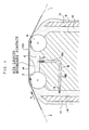
- Figure 1 is a sectional diagram showing structure of a coating device relating to an embodiment 1.
- Figure 2 is a perspective view, viewed from diagonally above, of the coating device shown in Figure 1.
- Figure 3 is a perspective view showing an example of the coating device shown in Figure 1, with a communicating channel with a form which differs from the form shown in Figure 1.
- Figure 4 is a perspective view showing an example of the coating device shown in Figure 1, with a communicating channel with a form which differs from the forms shown in Figures 1 and 2.
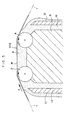
- Figure 5 is a sectional diagram showing structure of a coating device
relating to an
embodiment 2. -
- An example of a coating device of the present invention will be described below.
- A
coating device 100 relating to embodiment 1 is, as shown in Figure 1, an example of a belt mode of the present invention. Thecoating device 100 is a coating device which coats a platemaking layer formation solution on a roughened surface of a support web W, which is conveyed along the direction shown by arrow a. Thecoating device 100 is equipped with afirst side bar 2, asecond side bar 4 and an inter-bar liquid-poolingsection 6. Thefirst side bar 2 extends in a direction orthogonal to the conveyance direction of the support web W at a conveyance plane which is a conveyance path of the belt body. Thesecond side bar 4 is provided to be parallel with thefirst side bar 2, at a downstream side relative to thefirst side bar 2, and thesecond side bar 4 is at the same height as thefirst side bar 2. The inter-bar liquid-poolingsection 6 is located between thefirst side bar 2 and thesecond side bar 4. - The
first side bar 2 and thesecond side bar 4 both rotate in the same direction as the conveyance direction a, as viewed from a conveyance plane T, which is the conveyance path of the support web W. - A separation of the central axes of the
first side bar 2 and thesecond side bar 4 can be suitably specified in accordance with composition and viscosity of the platemaking layer formation solution. Generally, the separation is set such that a duration from when the support web W passes over thefirst side bar 2 until the support web W passes over thesecond side bar 4 is 0.02 seconds or less. - The
first side bar 2 and thesecond side bar 4 are supported from below by apedestal 8. The inter-bar liquid-poolingsection 6 is formed at an upper side of thepedestal 8. - A first side dam-form member (dam plate) 10, which is an example of a dam-form member of the present invention, is provided standing at an upstream side relative to the
pedestal 8. A second side dam-form member 12 is provided standing at a downstream side relative to thepedestal 8. Both the first side dam-form member 10 and the second side dam-form member 12 are standingly provided to be parallel with thepedestal 8. - A first side
supply flow channel 14 is formed between the first side dam-form member 10 and thepedestal 8. A second sidesupply flow channel 16 is formed between the second side dam-form member 12 and thepedestal 8. At the first sidesupply flow channel 14, the platemaking layer formation solution is supplied toward thefirst side bar 2 from below, and at the second sidesupply flow channel 16, the platemaking layer formation solution is supplied toward thesecond side bar 4 from below. The first sidesupply flow channel 14 and the second sidesupply flow channel 16 supply the platemaking layer formation solution respectively independently. - A connecting
flow channel 18, which communicates the inter-bar liquid-poolingsection 6 with the first sidesupply flow channel 14, is formed in thepedestal 8. - As shown in Figure 2, the connecting
flow channel 18 opens at the inter-bar liquid-poolingsection 6 in a slit form which is continuous along the direction orthogonal to the conveyance direction a. The connectingflow channel 18 is provided with avertical flow channel 18A and ahorizontal flow channel 18B. Thevertical flow channel 18A is a channel which extends downward in a vertical direction from the inter-bar liquid-poolingsection 6. Thehorizontal flow channel 18B is provided in a horizontal direction toward the first sidesupply flow channel 14 from a lower end of thevertical flow channel 18A. Thehorizontal flow channel 18B may be formed in a divided slit form which is divided in a lateral direction into two or more divisions. Thehorizontal flow channel 18B may also be a flow channel which is formed by numerous small holes which are mutually parallel. - The
vertical flow channel 18A may open at the inter-bar liquid-poolingsection 6 in a divided slit form as shown in Figure 3. Further, as shown in Figure 4, thevertical flow channel 18A may have small hole-form openings which are arranged in a row, or in two or more rows. - The first side dam-
form member 10 is formed such that a peak portion thereof is lower than the conveyance plane T. - In this
coating device 100, the platemaking layer formation solution supplied from the first sidesupply flow channel 14 is drawn up by thefirst side bar 2 and adheres to the roughened surface of the support web W. - A portion of the platemaking layer formation solution is conveyed downstream by the
first side bar 2 and is accumulated in the inter-bar liquid-poolingsection 6. - The support web W that has passed the
first side bar 2 passes the inter-bar liquid-poolingsection 6. - The support web W that has passed the inter-bar liquid-pooling
section 6 then passes over thesecond side bar 4. At thesecond side bar 4, the platemaking layer formation solution that has been applied to the support web W is regulated to a predetermined coating amount. - At the
second side bar 4, the platemaking layer formation solution is supplied from the second sidesupply flow channel 16. At the second sidesupply flow channel 16, the platemaking layer formation solution is supplied through a channel which is independent from the first sidesupply flow channel 14. Therefore, in any conditions, even if the supply flow amount at the first sidesupply flow channel 14 varies, the supply flow amount can be maintained to be stable at the second sidesupply flow channel 16. - Accordingly, because a particularly stable bead is formed at a periphery of the
second side bar 4, the occurrence of defects due to instability of this bead is effectively prevented. - When the support web W passes the inter-bar liquid-pooling
section 6, entrained air at the surface of the support web W is blocked by coating liquid that has accumulated in the inter-bar liquid-poolingsection 6. As a result, defects such as liquid interruption in the coating film do not occur. - At the first side
supply flow channel 14, because the platemaking layer formation solution circulates toward the upper side, there is a lowering of pressure at an opening portion at the first sidesupply flow channel 14 side of thehorizontal flow channel 18B. Because thehorizontal flow channel 18B communicates with the inter-bar liquid-poolingsection 6 via thevertical flow channel 18A, the platemaking layer formation solution in the inter-bar liquid-poolingsection 6 flows into thevertical flow channel 18A, and flows out to the first sidesupply flow channel 14 through thehorizontal flow channel 18B. Thus, as shown by the arrows b in Figure 1, a flow from the inter-bar liquid-poolingsection 6 through the connectingflow channel 18 and as far as the first sidesupply flow channel 14 is generated. - Here, a height of the first side
supply flow channel 14 is the same as a height of the first side dam-form member 10, and the height of the first side dam-form member 10 is lower than a height of the conveyance plane T, that is, a height of a peak portion of thefirst side bar 2. Accordingly, a liquid surface in the inter-bar liquid-poolingsection 6 descends to the height of the first side dam-form member 10, and a space is formed between the liquid surface and the support web W. Thus, an air-liquid boundary surface is formed in the inter-bar liquid-poolingsection 6. - Because the air-liquid boundary surface is formed in the inter-bar liquid-pooling
section 6 in this fashion, a stable bead of the platemaking layer formation solution is formed at an upstream side of thesecond side bar 4. Therefore, even in a case in which the support web W is conveyed at high speed and a platemaking layer formation solution with high viscosity is supplied from the first sidesupply flow channel 14, a stable coated surface that is free of stripe-form defects such as ripple lines, blanking lines, constant pitch lines, black unevenness is obtained. - Figure 5 shows another example of a coating device relating to the present invention. In Figure 5, reference numerals that are the same as in Figures 1 and 2 indicate elements that are the same as the structural elements that are indicated by those reference numerals in Figures 1 and 2.
- As shown in Figure 5, a
coating device 102 relating toembodiment 2 has the same structural elements as the coating device relating to embodiment 1, except that the connectingflow channel 18 is not formed in thepedestal 8. - In the
coating device 102, the platemaking layer formation solution supplied from the first sidesupply flow channel 14 is drawn up by thefirst side bar 2 to the upper side thereof, and adheres to the roughened surface of the support web W. - The support web W that has passed the
first side bar 2 passes the inter-bar liquid-poolingsection 6. - The support web W that has passed the inter-bar liquid-pooling
section 6 then passes over thesecond side bar 4. At thesecond side bar 4, the platemaking layer formation solution that has been applied to the support web W is regulated to a predetermined coating amount. - When the support web W passes the inter-bar liquid-pooling
section 6, entrained air at the surface of the support web W is blocked by coating liquid that has accumulated in the inter-bar liquid-poolingsection 6. Therefore, defects such as liquid interruption in the coating film do not occur. - Further, because there is no need to form a communicating flow channel in the
pedestal 8, the structure can be simplified. - Using the coating device shown in Figure 1, a photosensitive layer-forming solution was coated on a roughened surface of a support web. Coating conditions for the photosensitive layer-forming solution were as follows.
a. Thickness of support web W 0.3 mm b. Running speed of support web W 120 m/min c. Separation of centers between the first side bar 2 and thesecond side bar 421 mm d. Diameter of the first side bar 210 mm e. Rotation speed of the first side bar 250 rpm f. Width of downstream side slit 5 mm g. Surface tension of photosensitive layer-forming solution 23 mN/m h. Coating amount of photosensitive layer-forming solution at the first side supply flow channel 1450 cc/m2 i. Coated amount of photosensitive layer-forming solution after passing the second side bar 20 cc/m2 j. Viscosity of photosensitive layer-forming solution 20 cp - Results are shown in table 1. In table 1, "A" indicates a case in which the occurrence of black unevenness at the coated surface was not observed, and "B" represents a case in which the occurrence of black unevenness was observed to a slight extent.
Communicating channel Form of vertical channel Occurrence of white stripes Occurrence of black unevenness Occurrence of excessive coating Example 1 Present Divided slit form 0 /m2 (600 m2 inspected) B No Example 2 Present Continuous slit form 0 /m2 (600 m2 inspected) A No Reference Example 1 Absent -- 50 /m2 (50 m2 inspected) A Yes - As is shown in table 1, it can be seen that, when the platemaking layer formation solution was coated, stripe-form defects were generated at the coating device of Reference Example 1, in which an air-liquid boundary surface formation apparatus was not provided, whereas at the coating devices of Example 1 and Example 2, which were provided with air-liquid boundary surface formation apparatuses, the occurrence of stripe-form defects could be prevented.
- Hence, it can be seen that providing an air-liquid boundary surface formation apparatus is effective for preventing the occurrence of stripe-form defects in a case in which a high-viscosity platemaking layer formation liquid is coated at high speed.
- Note that, although the occurrence of stripe-form defects was observed with the coating device of Reference Example 1, it is thought that the occurrence of stripe-form defects might not be observed if the viscosity, surface tension of the photosensitive layer-forming solution were different.
- Liquid channeling of the platemaking layer formation solution was not observed with the coating devices of any of Examples 1 and 2 and Reference Example 1.
- A platemaking layer formation solution the same as that used in Example 1 was coated at a conveyance speed of 120 m/min. The separation of centers between the first side bar and the second side bar was varied in three steps: 20 mm, 40 mm and 50 mm. Results at these times are as shown in table 2.
Example 3 Example 4 Reference Example 2 Inter-bar separation 20 mm 40 mm 50 mm Inter-bar passage duration 0.01 s 0.02 s 0.025 s Occurrence of stripe-form defects Not occurred Not occurred Occurred - In table 2, the inter-bar separation represents the distance between the centers of the first side bar and the second side bar. The inter-bar passage duration represents a time duration from when the support web W passes above the first side bar until the support web W passes above the second side bar.
- In Example 3 and Example 4, in which the inter-bar passage duration was 0.02 seconds or less, none of white striping, black unevenness and excessive coating occurred. In contrast, in Reference Example 2, in which the inter-bar passage duration exceeded 0.02 seconds, each of these stripe-form defects was observed.
- Note that, even with the conditions represented in Reference Example 2, it is thought that the occurrence of the aforementioned stripe-form defects might not be observed if the surface tension and viscosity of the photosensitive layer-forming solution were different, the conveyance speed was higher.
- As is explained above, according to the present invention, a coating device and coating method can be provided with which, even in a case in which a belt body is run at high speed and coating is carried out, defects such as film discontinuities in a coating film do not occur, and stable coating can be carried out.
Claims (9)
- A coating device for coating a coating liquid on a surface of a belt body which is conveyed in a certain direction, the coating device comprising:a first side bar which extends along a transverse direction of a conveyance plane, which conveyance plane includes a conveyance path of the belt body;a second side bar at a downstream side relative to the first side bar, which extends in parallel with the first side bar;a first side coating liquid supply channel, which supplies the coating liquid at an upstream side at the first side bar; andan inter-bar liquid-pooling section located between the first side bar and the second side bar, which accumulates the coating liquid at a time of coating of the coating liquid.
- The coating device of claim 1, further comprising an air-liquid boundary surface formation apparatus which forms an air-liquid boundary surface, which includes a boundary surface between the coating liquid and air, between the belt body and the inter-bar liquid-pooling section.
- The coating device of claim 1, further comprising a second side coating liquid supply channel which supplies the coating liquid at a downstream side at the second side bar, wherein a supplied amount of the coating liquid at the second side coating liquid supply channel is controlled independently from a supplied amount of the coating liquid at the first side coating liquid supply channel.
- The coating device of claim 2 or 3, wherein the air-liquid boundary surface formation apparatus comprises a connecting channel which connects the inter-bar liquid-pooling section with the first side coating liquid supply channel.
- The coating device of claim 4, wherein the connecting channel comprises a coating liquid suction opening portion which opens along the transverse direction of the inter-bar liquid-pooling section, across substantially the whole width of the inter-bar liquid-pooling section.
- The coating device of claim 5, wherein the coating liquid suction opening portion comprises a continuous slit-form opening portion.
- The coating device of any one of claims 2 through 6, further comprising a first side dam-form member provided standing at an upstream side relative to the first side bar, the first side dam-form member forming a portion of a wall face of the first side coating liquid supply channel, wherein a peak portion of the first side dam-form member includes a height which is equal to or higher than a height of a bottom face of the inter-bar liquid-pooling section and which is lower than the conveyance plane.
- A coating method for coating a coating liquid at a surface of a belt body, the method comprising:conveying the belt body in a certain direction;forming an inter-bar liquid-pooling section between a first side bar, which extends along a transverse direction of a conveyance plane, and a second side bar, which extends in parallel with the first side bar at a downstream side of the first side bar; andusing the first side bar and the second side bar to coat the coating liquid at the surface.
- The coating method of claim 8, further comprising the step of, during the coating of the coating liquid, forming an air-liquid boundary surface, which is a boundary surface between the coating liquid and air, at the inter-bar liquid-pooling section.
Applications Claiming Priority (2)
| Application Number | Priority Date | Filing Date | Title |
|---|---|---|---|
| JP2002147940A JP4057841B2 (en) | 2002-05-22 | 2002-05-22 | Coating apparatus and coating method |
| JP2002147940 | 2002-05-22 |
Publications (2)
| Publication Number | Publication Date |
|---|---|
| EP1365287A1 true EP1365287A1 (en) | 2003-11-26 |
| EP1365287B1 EP1365287B1 (en) | 2008-05-21 |
Family
ID=29397857
Family Applications (1)
| Application Number | Title | Priority Date | Filing Date |
|---|---|---|---|
| EP03011545A Expired - Lifetime EP1365287B1 (en) | 2002-05-22 | 2003-05-21 | Coating device and coating method using the device |
Country Status (5)
| Country | Link |
|---|---|
| US (1) | US7041339B2 (en) |
| EP (1) | EP1365287B1 (en) |
| JP (1) | JP4057841B2 (en) |
| AT (1) | ATE396425T1 (en) |
| DE (1) | DE60321085D1 (en) |
Cited By (1)
| Publication number | Priority date | Publication date | Assignee | Title |
|---|---|---|---|---|
| US10413933B2 (en) | 2017-12-01 | 2019-09-17 | Metal Industries Research & Development Centre | Coating method and coating device |
Families Citing this family (7)
| Publication number | Priority date | Publication date | Assignee | Title |
|---|---|---|---|---|
| US7329437B2 (en) * | 2001-08-17 | 2008-02-12 | Fujifilm Corporation | Coating method and coating apparatus |
| US7527691B2 (en) * | 2003-01-17 | 2009-05-05 | Fujifilm Corporation | Coating apparatus and coating method |
| JP4419468B2 (en) * | 2003-08-08 | 2010-02-24 | Tdk株式会社 | Bar coating device |
| JP2007275818A (en) * | 2006-04-10 | 2007-10-25 | Fujifilm Corp | Bar coating method and apparatus |
| JP5162504B2 (en) * | 2009-03-13 | 2013-03-13 | 富士フイルム株式会社 | Bar coating apparatus and bar coating method |
| EP3069797B1 (en) * | 2015-03-17 | 2019-05-08 | Maan Intellectual Properties B.V. | Combination of device for applying a hot-melt to a web of material and a web of material |
| CN111469394B (en) * | 2020-04-13 | 2023-04-11 | 白建国 | Numerical control foam lines self-adhesion glass fiber mesh cloth parcel equipment |
Citations (5)
| Publication number | Priority date | Publication date | Assignee | Title |
|---|---|---|---|---|
| GB1192515A (en) * | 1967-05-22 | 1970-05-20 | Maxime Georges Willynck | Improvements in or relating to Coating Devices |
| US4116162A (en) * | 1977-08-31 | 1978-09-26 | Hoechst Aktiengesellschaft | Coating device |
| US4518637A (en) * | 1982-05-19 | 1985-05-21 | Fuji Photo Film Co., Ltd. | Coating solution metering method and apparatus |
| US4521459A (en) * | 1982-05-19 | 1985-06-04 | Fuji Photo Film Co., Ltd. | Coating method and apparatus |
| US5083527A (en) * | 1987-01-14 | 1992-01-28 | Fuji Photo Film Co., Ltd. | Coating apparatus and coating rod |
Family Cites Families (10)
| Publication number | Priority date | Publication date | Assignee | Title |
|---|---|---|---|---|
| JPS584589B2 (en) * | 1976-08-12 | 1983-01-27 | 富士写真フイルム株式会社 | Application method |
| JPS584589A (en) | 1981-07-01 | 1983-01-11 | 川嶋工業株式会社 | Sheath of knife |
| JP3108199B2 (en) | 1992-06-25 | 2000-11-13 | 川崎製鉄株式会社 | Plane shape control method in thick plate rolling |
| DE4444779B4 (en) * | 1994-12-15 | 2005-08-04 | Voith Sulzer Papiermaschinen Gmbh | Device for applying a liquid or pasty medium to a moving material web, in particular of paper or cardboard |
| DE19934441A1 (en) * | 1999-07-22 | 2001-01-25 | Voith Paper Patent Gmbh | Device for direct or indirect application of a liquid or pasty application medium to a running material web, in particular made of paper or cardboard |
| JP2002192050A (en) * | 2000-12-26 | 2002-07-10 | Fuji Photo Film Co Ltd | Coating apparatus and coating method |
| JP2002224608A (en) | 2001-01-31 | 2002-08-13 | Fuji Photo Film Co Ltd | Method and apparatus for applying coating liquid |
| JP4319364B2 (en) | 2001-08-17 | 2009-08-26 | 富士フイルム株式会社 | Coating apparatus and coating method |
| US7329437B2 (en) * | 2001-08-17 | 2008-02-12 | Fujifilm Corporation | Coating method and coating apparatus |
| JP2003103212A (en) | 2001-09-28 | 2003-04-08 | Fuji Photo Film Co Ltd | Coating apparatus and coating method |
-
2002
- 2002-05-22 JP JP2002147940A patent/JP4057841B2/en not_active Expired - Fee Related
-
2003
- 2003-05-15 US US10/437,973 patent/US7041339B2/en not_active Expired - Fee Related
- 2003-05-21 AT AT03011545T patent/ATE396425T1/en not_active IP Right Cessation
- 2003-05-21 EP EP03011545A patent/EP1365287B1/en not_active Expired - Lifetime
- 2003-05-21 DE DE60321085T patent/DE60321085D1/en not_active Expired - Lifetime
Patent Citations (5)
| Publication number | Priority date | Publication date | Assignee | Title |
|---|---|---|---|---|
| GB1192515A (en) * | 1967-05-22 | 1970-05-20 | Maxime Georges Willynck | Improvements in or relating to Coating Devices |
| US4116162A (en) * | 1977-08-31 | 1978-09-26 | Hoechst Aktiengesellschaft | Coating device |
| US4518637A (en) * | 1982-05-19 | 1985-05-21 | Fuji Photo Film Co., Ltd. | Coating solution metering method and apparatus |
| US4521459A (en) * | 1982-05-19 | 1985-06-04 | Fuji Photo Film Co., Ltd. | Coating method and apparatus |
| US5083527A (en) * | 1987-01-14 | 1992-01-28 | Fuji Photo Film Co., Ltd. | Coating apparatus and coating rod |
Cited By (1)
| Publication number | Priority date | Publication date | Assignee | Title |
|---|---|---|---|---|
| US10413933B2 (en) | 2017-12-01 | 2019-09-17 | Metal Industries Research & Development Centre | Coating method and coating device |
Also Published As
| Publication number | Publication date |
|---|---|
| US7041339B2 (en) | 2006-05-09 |
| US20030217692A1 (en) | 2003-11-27 |
| DE60321085D1 (en) | 2008-07-03 |
| JP2003340344A (en) | 2003-12-02 |
| EP1365287B1 (en) | 2008-05-21 |
| ATE396425T1 (en) | 2008-06-15 |
| JP4057841B2 (en) | 2008-03-05 |
Similar Documents
| Publication | Publication Date | Title |
|---|---|---|
| US7041339B2 (en) | Coating device and coating method using the device | |
| US20080175998A1 (en) | Coating device, and coating method using said device | |
| JP2002192050A (en) | Coating apparatus and coating method | |
| US20080063805A1 (en) | Coating apparatus and coating method | |
| EP0425562B1 (en) | Curtain coating method and apparatus | |
| JP2565412B2 (en) | Coating device | |
| JP2934186B2 (en) | Application method | |
| EP0930530B1 (en) | Curtain coating apparatus | |
| US6294023B1 (en) | Curtain coating apparatus and method | |
| JPH07108207A (en) | Coating apparatus | |
| JP4024156B2 (en) | Coating apparatus and coating method | |
| JP4090318B2 (en) | Coating apparatus and coating method | |
| JP4319364B2 (en) | Coating apparatus and coating method | |
| JP2572333B2 (en) | Multi-layer coating equipment for dam type paint | |
| JP4857813B2 (en) | Coating apparatus, coating method, and method for producing coating film forming web | |
| JP2004230353A (en) | Bar coater and application method | |
| JP3854185B2 (en) | Coating apparatus and coating method | |
| JP2000005681A (en) | Device and method for coating | |
| JPS5832776Y2 (en) | flow coater | |
| JP2003275642A (en) | Coating device and coating method | |
| JP2852865B2 (en) | Coating device | |
| JP2004089949A (en) | Coating apparatus and coating method | |
| JPH11138079A (en) | Method and apparatus for curtain coating | |
| JPH11169770A (en) | Coating device | |
| JPH08131923A (en) | Method and device for coating |
Legal Events
| Date | Code | Title | Description |
|---|---|---|---|
| PUAI | Public reference made under article 153(3) epc to a published international application that has entered the european phase |
Free format text: ORIGINAL CODE: 0009012 |
|
| AK | Designated contracting states |
Kind code of ref document: A1 Designated state(s): AT BE BG CH CY CZ DE DK EE ES FI FR GB GR HU IE IT LI LU MC NL PT RO SE SI SK TR |
|
| AX | Request for extension of the european patent |
Extension state: AL LT LV MK |
|
| 17P | Request for examination filed |
Effective date: 20040420 |
|
| AKX | Designation fees paid |
Designated state(s): AT BE BG CH CY CZ DE DK EE ES FI FR GB GR HU IE IT LI LU MC NL PT RO SE SI SK TR |
|
| 17Q | First examination report despatched |
Effective date: 20050125 |
|
| RAP1 | Party data changed (applicant data changed or rights of an application transferred) |
Owner name: FUJIFILM CORPORATION |
|
| 17Q | First examination report despatched |
Effective date: 20050125 |
|
| GRAP | Despatch of communication of intention to grant a patent |
Free format text: ORIGINAL CODE: EPIDOSNIGR1 |
|
| GRAS | Grant fee paid |
Free format text: ORIGINAL CODE: EPIDOSNIGR3 |
|
| GRAA | (expected) grant |
Free format text: ORIGINAL CODE: 0009210 |
|
| AK | Designated contracting states |
Kind code of ref document: B1 Designated state(s): AT BE BG CH CY CZ DE DK EE ES FI FR GB GR HU IE IT LI LU MC NL PT RO SE SI SK TR |
|
| REG | Reference to a national code |
Ref country code: GB Ref legal event code: FG4D |
|
| REG | Reference to a national code |
Ref country code: CH Ref legal event code: EP |
|
| REF | Corresponds to: |
Ref document number: 60321085 Country of ref document: DE Date of ref document: 20080703 Kind code of ref document: P |
|
| REG | Reference to a national code |
Ref country code: IE Ref legal event code: FG4D |
|
| PG25 | Lapsed in a contracting state [announced via postgrant information from national office to epo] |
Ref country code: SI Free format text: LAPSE BECAUSE OF FAILURE TO SUBMIT A TRANSLATION OF THE DESCRIPTION OR TO PAY THE FEE WITHIN THE PRESCRIBED TIME-LIMIT Effective date: 20080521 |
|
| PG25 | Lapsed in a contracting state [announced via postgrant information from national office to epo] |
Ref country code: ES Free format text: LAPSE BECAUSE OF FAILURE TO SUBMIT A TRANSLATION OF THE DESCRIPTION OR TO PAY THE FEE WITHIN THE PRESCRIBED TIME-LIMIT Effective date: 20080901 Ref country code: FI Free format text: LAPSE BECAUSE OF FAILURE TO SUBMIT A TRANSLATION OF THE DESCRIPTION OR TO PAY THE FEE WITHIN THE PRESCRIBED TIME-LIMIT Effective date: 20080521 |
|
| NLV1 | Nl: lapsed or annulled due to failure to fulfill the requirements of art. 29p and 29m of the patents act | ||
| PG25 | Lapsed in a contracting state [announced via postgrant information from national office to epo] |
Ref country code: NL Free format text: LAPSE BECAUSE OF FAILURE TO SUBMIT A TRANSLATION OF THE DESCRIPTION OR TO PAY THE FEE WITHIN THE PRESCRIBED TIME-LIMIT Effective date: 20080521 Ref country code: AT Free format text: LAPSE BECAUSE OF FAILURE TO SUBMIT A TRANSLATION OF THE DESCRIPTION OR TO PAY THE FEE WITHIN THE PRESCRIBED TIME-LIMIT Effective date: 20080521 |
|
| PG25 | Lapsed in a contracting state [announced via postgrant information from national office to epo] |
Ref country code: MC Free format text: LAPSE BECAUSE OF NON-PAYMENT OF DUE FEES Effective date: 20080531 |
|
| REG | Reference to a national code |
Ref country code: CH Ref legal event code: PL |
|
| PG25 | Lapsed in a contracting state [announced via postgrant information from national office to epo] |
Ref country code: LI Free format text: LAPSE BECAUSE OF NON-PAYMENT OF DUE FEES Effective date: 20080531 Ref country code: DK Free format text: LAPSE BECAUSE OF FAILURE TO SUBMIT A TRANSLATION OF THE DESCRIPTION OR TO PAY THE FEE WITHIN THE PRESCRIBED TIME-LIMIT Effective date: 20080521 Ref country code: CZ Free format text: LAPSE BECAUSE OF FAILURE TO SUBMIT A TRANSLATION OF THE DESCRIPTION OR TO PAY THE FEE WITHIN THE PRESCRIBED TIME-LIMIT Effective date: 20080521 Ref country code: SE Free format text: LAPSE BECAUSE OF FAILURE TO SUBMIT A TRANSLATION OF THE DESCRIPTION OR TO PAY THE FEE WITHIN THE PRESCRIBED TIME-LIMIT Effective date: 20080821 Ref country code: PT Free format text: LAPSE BECAUSE OF FAILURE TO SUBMIT A TRANSLATION OF THE DESCRIPTION OR TO PAY THE FEE WITHIN THE PRESCRIBED TIME-LIMIT Effective date: 20081021 Ref country code: CH Free format text: LAPSE BECAUSE OF NON-PAYMENT OF DUE FEES Effective date: 20080531 |
|
| PG25 | Lapsed in a contracting state [announced via postgrant information from national office to epo] |
Ref country code: BE Free format text: LAPSE BECAUSE OF FAILURE TO SUBMIT A TRANSLATION OF THE DESCRIPTION OR TO PAY THE FEE WITHIN THE PRESCRIBED TIME-LIMIT Effective date: 20080521 Ref country code: SK Free format text: LAPSE BECAUSE OF FAILURE TO SUBMIT A TRANSLATION OF THE DESCRIPTION OR TO PAY THE FEE WITHIN THE PRESCRIBED TIME-LIMIT Effective date: 20080521 Ref country code: RO Free format text: LAPSE BECAUSE OF FAILURE TO SUBMIT A TRANSLATION OF THE DESCRIPTION OR TO PAY THE FEE WITHIN THE PRESCRIBED TIME-LIMIT Effective date: 20080521 |
|
| PLBE | No opposition filed within time limit |
Free format text: ORIGINAL CODE: 0009261 |
|
| STAA | Information on the status of an ep patent application or granted ep patent |
Free format text: STATUS: NO OPPOSITION FILED WITHIN TIME LIMIT |
|
| 26N | No opposition filed |
Effective date: 20090224 |
|
| GBPC | Gb: european patent ceased through non-payment of renewal fee |
Effective date: 20080821 |
|
| PG25 | Lapsed in a contracting state [announced via postgrant information from national office to epo] |
Ref country code: IE Free format text: LAPSE BECAUSE OF NON-PAYMENT OF DUE FEES Effective date: 20080521 Ref country code: BG Free format text: LAPSE BECAUSE OF FAILURE TO SUBMIT A TRANSLATION OF THE DESCRIPTION OR TO PAY THE FEE WITHIN THE PRESCRIBED TIME-LIMIT Effective date: 20080821 Ref country code: EE Free format text: LAPSE BECAUSE OF FAILURE TO SUBMIT A TRANSLATION OF THE DESCRIPTION OR TO PAY THE FEE WITHIN THE PRESCRIBED TIME-LIMIT Effective date: 20080521 |
|
| REG | Reference to a national code |
Ref country code: FR Ref legal event code: ST Effective date: 20090331 |
|
| PG25 | Lapsed in a contracting state [announced via postgrant information from national office to epo] |
Ref country code: IT Free format text: LAPSE BECAUSE OF FAILURE TO SUBMIT A TRANSLATION OF THE DESCRIPTION OR TO PAY THE FEE WITHIN THE PRESCRIBED TIME-LIMIT Effective date: 20080521 Ref country code: FR Free format text: LAPSE BECAUSE OF NON-PAYMENT OF DUE FEES Effective date: 20080602 |
|
| PG25 | Lapsed in a contracting state [announced via postgrant information from national office to epo] |
Ref country code: GB Free format text: LAPSE BECAUSE OF NON-PAYMENT OF DUE FEES Effective date: 20080821 |
|
| PG25 | Lapsed in a contracting state [announced via postgrant information from national office to epo] |
Ref country code: CY Free format text: LAPSE BECAUSE OF FAILURE TO SUBMIT A TRANSLATION OF THE DESCRIPTION OR TO PAY THE FEE WITHIN THE PRESCRIBED TIME-LIMIT Effective date: 20080521 Ref country code: HU Free format text: LAPSE BECAUSE OF FAILURE TO SUBMIT A TRANSLATION OF THE DESCRIPTION OR TO PAY THE FEE WITHIN THE PRESCRIBED TIME-LIMIT Effective date: 20081122 Ref country code: LU Free format text: LAPSE BECAUSE OF NON-PAYMENT OF DUE FEES Effective date: 20080521 |
|
| PG25 | Lapsed in a contracting state [announced via postgrant information from national office to epo] |
Ref country code: TR Free format text: LAPSE BECAUSE OF FAILURE TO SUBMIT A TRANSLATION OF THE DESCRIPTION OR TO PAY THE FEE WITHIN THE PRESCRIBED TIME-LIMIT Effective date: 20080521 |
|
| PG25 | Lapsed in a contracting state [announced via postgrant information from national office to epo] |
Ref country code: GR Free format text: LAPSE BECAUSE OF FAILURE TO SUBMIT A TRANSLATION OF THE DESCRIPTION OR TO PAY THE FEE WITHIN THE PRESCRIBED TIME-LIMIT Effective date: 20080822 |
|
| PGFP | Annual fee paid to national office [announced via postgrant information from national office to epo] |
Ref country code: DE Payment date: 20120516 Year of fee payment: 10 |
|
| PG25 | Lapsed in a contracting state [announced via postgrant information from national office to epo] |
Ref country code: DE Free format text: LAPSE BECAUSE OF NON-PAYMENT OF DUE FEES Effective date: 20131203 |
|
| REG | Reference to a national code |
Ref country code: DE Ref legal event code: R119 Ref document number: 60321085 Country of ref document: DE Effective date: 20131203 |