EP1365236A2 - Measuring cell, apparatus and method for determining foreign matter content in a fluid - Google Patents
Measuring cell, apparatus and method for determining foreign matter content in a fluid Download PDFInfo
- Publication number
- EP1365236A2 EP1365236A2 EP20030005925 EP03005925A EP1365236A2 EP 1365236 A2 EP1365236 A2 EP 1365236A2 EP 20030005925 EP20030005925 EP 20030005925 EP 03005925 A EP03005925 A EP 03005925A EP 1365236 A2 EP1365236 A2 EP 1365236A2
- Authority
- EP
- European Patent Office
- Prior art keywords
- measuring
- liquid
- measuring chamber
- determining
- measured
- Prior art date
- Legal status (The legal status is an assumption and is not a legal conclusion. Google has not performed a legal analysis and makes no representation as to the accuracy of the status listed.)
- Withdrawn
Links
Images


Classifications
-
- G—PHYSICS
- G01—MEASURING; TESTING
- G01N—INVESTIGATING OR ANALYSING MATERIALS BY DETERMINING THEIR CHEMICAL OR PHYSICAL PROPERTIES
- G01N35/00—Automatic analysis not limited to methods or materials provided for in any single one of groups G01N1/00 - G01N33/00; Handling materials therefor
- G01N35/10—Devices for transferring samples or any liquids to, in, or from, the analysis apparatus, e.g. suction devices, injection devices
- G01N35/1095—Devices for transferring samples or any liquids to, in, or from, the analysis apparatus, e.g. suction devices, injection devices for supplying the samples to flow-through analysers
- G01N35/1097—Devices for transferring samples or any liquids to, in, or from, the analysis apparatus, e.g. suction devices, injection devices for supplying the samples to flow-through analysers characterised by the valves
-
- G—PHYSICS
- G01—MEASURING; TESTING
- G01N—INVESTIGATING OR ANALYSING MATERIALS BY DETERMINING THEIR CHEMICAL OR PHYSICAL PROPERTIES
- G01N13/00—Investigating surface or boundary effects, e.g. wetting power; Investigating diffusion effects; Analysing materials by determining surface, boundary, or diffusion effects
- G01N13/02—Investigating surface tension of liquids
-
- G—PHYSICS
- G01—MEASURING; TESTING
- G01N—INVESTIGATING OR ANALYSING MATERIALS BY DETERMINING THEIR CHEMICAL OR PHYSICAL PROPERTIES
- G01N15/00—Investigating characteristics of particles; Investigating permeability, pore-volume, or surface-area of porous materials
- G01N15/06—Investigating concentration of particle suspensions
-
- G—PHYSICS
- G01—MEASURING; TESTING
- G01N—INVESTIGATING OR ANALYSING MATERIALS BY DETERMINING THEIR CHEMICAL OR PHYSICAL PROPERTIES
- G01N29/00—Investigating or analysing materials by the use of ultrasonic, sonic or infrasonic waves; Visualisation of the interior of objects by transmitting ultrasonic or sonic waves through the object
- G01N29/02—Analysing fluids
-
- G—PHYSICS
- G01—MEASURING; TESTING
- G01N—INVESTIGATING OR ANALYSING MATERIALS BY DETERMINING THEIR CHEMICAL OR PHYSICAL PROPERTIES
- G01N29/00—Investigating or analysing materials by the use of ultrasonic, sonic or infrasonic waves; Visualisation of the interior of objects by transmitting ultrasonic or sonic waves through the object
- G01N29/22—Details, e.g. general constructional or apparatus details
- G01N29/222—Constructional or flow details for analysing fluids
-
- G—PHYSICS
- G01—MEASURING; TESTING
- G01N—INVESTIGATING OR ANALYSING MATERIALS BY DETERMINING THEIR CHEMICAL OR PHYSICAL PROPERTIES
- G01N29/00—Investigating or analysing materials by the use of ultrasonic, sonic or infrasonic waves; Visualisation of the interior of objects by transmitting ultrasonic or sonic waves through the object
- G01N29/22—Details, e.g. general constructional or apparatus details
- G01N29/32—Arrangements for suppressing undesired influences, e.g. temperature or pressure variations, compensating for signal noise
- G01N29/326—Arrangements for suppressing undesired influences, e.g. temperature or pressure variations, compensating for signal noise compensating for temperature variations
-
- G—PHYSICS
- G01—MEASURING; TESTING
- G01N—INVESTIGATING OR ANALYSING MATERIALS BY DETERMINING THEIR CHEMICAL OR PHYSICAL PROPERTIES
- G01N29/00—Investigating or analysing materials by the use of ultrasonic, sonic or infrasonic waves; Visualisation of the interior of objects by transmitting ultrasonic or sonic waves through the object
- G01N29/44—Processing the detected response signal, e.g. electronic circuits specially adapted therefor
- G01N29/4409—Processing the detected response signal, e.g. electronic circuits specially adapted therefor by comparison
- G01N29/4427—Processing the detected response signal, e.g. electronic circuits specially adapted therefor by comparison with stored values, e.g. threshold values
-
- G—PHYSICS
- G01—MEASURING; TESTING
- G01N—INVESTIGATING OR ANALYSING MATERIALS BY DETERMINING THEIR CHEMICAL OR PHYSICAL PROPERTIES
- G01N33/00—Investigating or analysing materials by specific methods not covered by groups G01N1/00 - G01N31/00
- G01N33/26—Oils; viscous liquids; paints; inks
- G01N33/28—Oils, i.e. hydrocarbon liquids
- G01N33/2894—Oils, i.e. hydrocarbon liquids for metal working or machining
-
- G—PHYSICS
- G01—MEASURING; TESTING
- G01N—INVESTIGATING OR ANALYSING MATERIALS BY DETERMINING THEIR CHEMICAL OR PHYSICAL PROPERTIES
- G01N2291/00—Indexing codes associated with group G01N29/00
- G01N2291/01—Indexing codes associated with the measuring variable
- G01N2291/011—Velocity or travel time
-
- G—PHYSICS
- G01—MEASURING; TESTING
- G01N—INVESTIGATING OR ANALYSING MATERIALS BY DETERMINING THEIR CHEMICAL OR PHYSICAL PROPERTIES
- G01N2291/00—Indexing codes associated with group G01N29/00
- G01N2291/01—Indexing codes associated with the measuring variable
- G01N2291/015—Attenuation, scattering
-
- G—PHYSICS
- G01—MEASURING; TESTING
- G01N—INVESTIGATING OR ANALYSING MATERIALS BY DETERMINING THEIR CHEMICAL OR PHYSICAL PROPERTIES
- G01N2291/00—Indexing codes associated with group G01N29/00
- G01N2291/02—Indexing codes associated with the analysed material
- G01N2291/028—Material parameters
- G01N2291/02818—Density, viscosity
-
- G—PHYSICS
- G01—MEASURING; TESTING
- G01N—INVESTIGATING OR ANALYSING MATERIALS BY DETERMINING THEIR CHEMICAL OR PHYSICAL PROPERTIES
- G01N2291/00—Indexing codes associated with group G01N29/00
- G01N2291/04—Wave modes and trajectories
- G01N2291/045—External reflections, e.g. on reflectors
Definitions
- the invention relates to a measuring chamber, a measuring device and a measuring method to determine the foreign matter content of a liquid.
- the invention continues by determining the concentration of individuals Components in a liquid multi-component system, an entry of water-insoluble components in particular both liquid and solid, such as oils or particles, is of interest.
- Corresponding monitoring alternatives are, for example, from DE 41 36 442 A1, DE 199 06 940 A1 and known from DE 199 27 666 A1.
- DE 41 36 442 A1 one with the dynamic surface tension of a liquid using a correlated value of a bubble tensiometer. Based on this value, then processing of the cleaning liquid and / or replenishment of the cleaning agent.
- DE 199 06 940 A1 discloses a corresponding examination procedure or a suitable one Measuring device in which one of both the detergent concentration as well as the size dependent on the load and at least on the detergent concentration or size dependent on the load and from these quantities a statement about the detergent concentration and / or the load is hit.
- the invention proposes a measuring chamber, a measuring device and a measuring method for determining the foreign matter content of a liquid with the features of the attached main claims.
- the invention proposes a measuring chamber for determining a Foreign matter content of a liquid with a bottom area and a above the upper area, which is characterized by a in the upper Area arranged suction marks. Accordingly the invention also proposes a measuring method for determining the foreign matter content a liquid in which a measured variable in a Measuring chamber is determined and which is characterized in that before Start the measurement with a sample of the liquid to be measured a negative pressure generated in the measuring chamber is conveyed into the measuring chamber becomes.
- the liquid or sample quantity to be measured can be sucked through be transferred very gently into a corresponding measuring chamber. In this way, unnecessary turbulence can in particular Air pockets are avoided, which may be the corresponding Falsify measurement result.
- the inlet opening in the bottom area of the measuring chamber is arranged, a smooth inflow of the liquid to be measured can be guaranteed.
- the inlet opening preferably also serves as an outlet opening.
- the invention proposes a measuring device for determining the Foreign matter content of a liquid, which means for determining of sound properties of the liquid and means for determining the Conductivity, surface tension and / or pH of the liquid includes.
- a measuring device for determining the Foreign matter content of a liquid which means for determining of sound properties of the liquid and means for determining the Conductivity, surface tension and / or pH of the liquid includes.
- the invention proposes cumulatively or alternatively, in which Measuring chamber tempering plates must be provided in order to be as uniform as possible and enable rapid tempering.
- Heating coils or the like are only on the edge of a measuring cell provided that the temperature control of the can cause liquid contained therein.
- the invention Temperature control plates, which in particular in the wall of a corresponding Measuring chamber may be provided or this wall at least partially can form, the time for a tempering can be considerable shortened and ensure a more even temperature control.
- the tempering plates stainless steel, as this material is used for Relatively low cost stable against chemical attacks and yet is relatively good heat conductor.
- Peltier elements are preferably used for tempering, which can be attached to the temperature control plates, for example.
- the temperature control plates can be used both for heating and for heating Serve cooling.
- such elements have been proportionate short response times so that the temperature can be regulated very precisely leaves, which in turn increases the measuring accuracy considerably can.
- the measuring chamber preferably has a housing made of plastic.
- Plastic is a relatively poor heat conductor, so this causes the measuring chamber proportionally to the outside without additional measures is well thermally insulated. This can ensure that with tempering only the liquid itself and a small one Edge area that is in contact with the liquid varies thermally, whereby the total mass to be tempered is reduced and the total duration is reduced for the temperature control.
- a housing made of polyacetals or polyoxymethylene has proven advantageous (POM) proved that this material protects against chemical attacks, for example can start from the liquid itself, relatively is stable.
- the above-described configurations of the measuring chamber are particularly suitable in interaction with the measurement of sound or ultrasonic properties, such as in particular runtime measurements or measurements of the Damping. In this context, they lead in particular to a shortening the measurement duration as well as reliable and reproducible measurement results.
- At least one sound transmitter and / or receiver is preferably behind a membrane provided in one piece with a chamber wall.
- a membrane provided in one piece with a chamber wall.
- the membrane is made with a lower roughness depth than that remaining housings, which further distorts the measurement let reduce.
- the membrane also leads to the corresponding Sound transmitter or receiver not directly with the one to be measured Liquid is in contact and in this way through the liquid cannot be attacked. It is understood that the presence such a membrane also independent of the other features the measuring chamber according to the invention is advantageous.
- a sound reflector in particular a, in the measuring chamber Sound reflector plate provided.
- the sound reflector made of a different material than one behind it Housing wall.
- a Sound reflector made of stainless steel, especially in combination with one Plastic housing provides sufficiently good results.
- such a sound reflector is also independent of the other features present invention can advantageously be used. In particular this can also reduce the number of measuring devices, which can save costs.
- the measuring accuracy for runtime and damping measurements of ultrasound can also be increased cumulatively or alternatively if one Sequence of ultrasonic pulses, for example of 200 individual pulses, for the measurement is introduced into the liquid to be measured. This sequence of pulses can then be subjected to normal statistics.
- the overall evaluation is particularly easy if only measurement results be allowed at a certain time because that time, for example depending on falling below a certain fluctuation range of the measurement results is set.
- the measurements be carried out in conjunction with temperature control processes can the fluctuation or the change of the measured values as an indication for a Temperature change can be evaluated. In this respect, if the fluctuation falls below a previously selected value, it is assumed that the liquid to be measured has the desired temperature is.
- the optical sensor can in particular comprise an optical transmitter and an optical receiver, wherein these elements can also be designed as a unit.
- a simple optical measurement can be, for example, a transmission measurement be made.
- the optical transmitter and the optical receiver a measuring section to be irradiated.
- the transmitter emits the signal
- the receiver registers, for example, in which Intensity the signal arrives.
- disturbances can lie. Especially when flowing in a Liquid is measured, often interfere with the flow entrained Air bubbles the measurement.
- a measuring device or a measuring chamber an alternative is to determine the foreign substance content of a liquid or cumulatively a sensor for measuring intramolecular properties is provided. For example, with high precision from molecular resonances of the mixture to be measured is directly based on the substances present there become.
- the senor does not require direct contact with the one to be measured Liquid. Rather, it can, for example, by optics from the Liquid must be separated, so that this advantage even with optical measurements occurs.
- the sensors can measure the fluid on a molecular level Influence level via microwave excitation or fluorescence excitation. There is no macroscopic intervention in the liquid.
- the molecularly focused measurement also has the advantage that the underlying sizes largely independent of integral properties of the liquid to be measured. Influence as an example Surface tension, temperature, density and others in particular Viscosity-determining variables determine the molecular resonance over large value ranges Not.
- intramolecular measurements such as fluorescence measurements or microwave resonance measurements or other measurements, those with selected constituents of atoms or molecules of the liquid components to be monitored interact, the advantage that external influences, such as air bubbles, temperature or Pressure fluctuations, other liquid components or color changes or the like, little or no impact on the Have measurement result.
- external influences such as air bubbles, temperature or Pressure fluctuations, other liquid components or color changes or the like
- it is used for such measurements in the Usually not necessary macroscopically, for example by taking samples, Temperature change or chemical interventions or titration in which too measure liquid or liquid circuits.
- time-resolved fluorescence measurements especially time-resolved X-ray fluorescence measurements, as these especially largely independent of other physical or chemical Environmental conditions can work.
- the appropriate measurement parameters according to the ones to be checked Particles determined beforehand, before actually taking online measurements be performed.
- Such intramolecular measurements such as fluorescence measurements, X-ray fluorescence measurements or microwave resonance measurements or other measurements, those with selected constituents of atoms or molecules of those to be monitored Liquid components interact, whether time-resolved or not, also for the determination of surface contamination with appropriate Liquids can be used, with a corresponding one Excitation beam guided over the surfaces to be checked can be.
- the same measurement parameters in particular, can be used here also found for flowing samples as selective for the measurement, as Measurement parameters can be used for surface testing.
- a laser can be radiated into a fiber that conducts laser light which lies in the mixture to be measured and at least partially there is not covered. Due to the light emission directly from the fiber into the Mixture affect the optical properties of the mixture in one Interaction of the laser light in the fiber. Depending on the ones to be measured Mixture present substances and the corresponding physical Molecular properties is irradiated at different wavelengths Laser light to determine a different molecular resonance.
- a receiver determines the intensity spectrum of the fiber emerging Laser light and compares it with the absorption line of a molecule, whose concentration is to be determined. From the change in intensity of the laser light emerging from the fiber can affect the concentration of the respective molecule in the area around the uncovered section the fiber are closed.
- the receiver can also use the fluorescent radiation emanating from the mixture at least two time intervals after a laser light pulse record the ratio between the measurement signals recorded in the intervals calculate and this with known for different concentrations Compare fluorescence decay curves to determine the concentration in Determine mixture.
- the sensors are preferably in a flow through the entire line Measuring arrangement provided. While it makes sense to take measurements so far to be carried out as possible on a stationary medium. This is how the DE beats 195 07 119 C2 that pulsed laser radiation onto a stationary sample in directed into a vessel and the fluorescence radiation is measured. In reverse of these, however, it turned out to be advantageous, the measurement in or on a current. So at first it is observed less often that substances accumulate in the measuring area, which then the measurement results can influence and falsify. In addition, the homogeneity decreases mixing in a standing sample tends to decrease.
- a homogenizing device can therefore advantageously be used to achieve thorough mixing be provided in the flow-through line.
- the sensors flow in a sideline are arranged.
- the sideline for example a branched one and pipe running parallel to the primary line, can be as small as possible Influence on the flow in the primary line also strongly on the flow be influenced.
- Such a bypass can even be completely closed , for example for taking reference samples or for rinsing or Cleaning purposes.
- means for speed adjustment can also be used in the flow through the line can be provided.
- Methods of fluorescence radiation detection are, for example Time intervals of a few hundred nanoseconds are required. So it has to be ensured be that the flowing mixture in its middle or preferably greatest local flow velocity within this period cannot flow completely through the measuring range.
- speed adjustment can therefore, for example, if the pipe flow is too fast a cross-sectional widening of the conduit can be made.
- an optical sensor can be used or a sensor for measuring intramolecular properties also non-invasive be arranged on a window, which is in particular in a The wall of the liquid line or a container nestles flush.
- the measurement can also be non-invasive on a free-mirror line or the liquid level of the mixture in a vessel become.
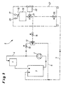
- a cleaning agent is required Consumer 1 via a supply pump 2 with cleaning liquid supplied from a central supply 3.
- the consumer 1 can, for example a CNC machine or the like.
- the Cleaning liquid which is in a corresponding supply circuit 4 circulates, contaminated on the one hand by foreign matter and on the other hand reduced in terms of their detergent concentration, so that after must be prepared or exchanged for a certain time.
- a measuring device 5 which on the one hand Primary line 6 (shown with a line) and on the other hand a secondary line 7 (shown in broken lines).
- Primary line 6 shown with a line
- secondary line 7 shown in broken lines.
- Both the primary line 6 and the secondary line 7 are in circulation executed. With alternative design variants, however, they can also individually or both lead to disposal.
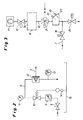
- the primary circuit 6 shown in particular in FIG. 2 comprises in detail behind the inlet of the actual supply circuit 4 manual shut-off device 8, a pressure limiter 9, a safety valve 10, a pressure indicator 11, an analysis filter 12 and a flow warmer 13 before it flows into the central supply 3.
- the safety valve 10 is controlled by a leak warning probe 14, which monitors the escape of liquid into a safety trough 15.
- the secondary line 7 branches off from the primary line 6 on the analysis filter 12. It is shown in detail in FIG. 3.
- the inflow to the secondary line 7 is controlled by a supply valve 16.
- the Liquid to be measured from the secondary circuit 7 by means of a pump 17, preferably by means of a rotary vane pump, into the measuring chamber 18 sucked.
- a valve 19 is located between the measuring chamber 18 and the pump 17 provided that switching between filling and emptying the Measuring chamber.
- the present exemplary embodiment is used for emptying a membrane pump 20, by means of which the located in the measuring chamber Liquid is transferred back to the secondary line 7.
- a changeover valve 21 is also provided, which leads to a calibration unit 22.
- a tempering tank 23 which on the one hand a pre-tempering the liquid to be measured and on the other hand a pH value measurement 24 and Conductivity measurement 25 is used, the latter two measurements by the Temperature control can also be increased in its accuracy.
- the secondary line 7 comprises a discharge valve 26, which in particular can be used in conjunction with the valve 16 through the membrane pump 20 introduced into the secondary line 7 liquid in the to let the desired direction flow.
- the measuring chamber 18 shown in detail in FIGS. 4 and 5 comprises in Essentially a measuring space 27, which is made of a base body 28 made of POM is surrounded, which is arranged via insulation 29 in a housing 30 is.
- the measuring room itself has a diamond-shaped cross-section, such as particularly evident from FIG. 5. This results in a tapering Bottom area 31, so that a corresponding liquid easily can run in or out through a feed line 32.
- the measuring chamber 18 also includes a level sensor 33, which in particular outputs when the measuring space 27 is completely filled and a corresponding one Measurement can be made.
- the measuring room is over a suction line 34 is subjected to a negative pressure or positive pressure, to initiate the desired fluid movement.
- the measuring chamber comprises an ultrasonic sensor 35, which is in active connection with the measuring chamber 27 via a membrane 36, which with a reflector plate 37, which is opposite the ultrasonic sensor, interacts and which by means of an adapter 38 which on a Pressure ring 39 acts in the base body is fixed.
- the membrane 36 is integrally formed with the base body 28 and in the present embodiment about 1mm thick. Your surface was pre-existing Example polished to achieve a small depth. It goes without saying that in an alternative embodiment the ultrasonic sensor, which in the present case serves as both a transmitter and a receiver, can also be arranged in the bottom region 31, and also in this embodiment a reflector plate 37 arranged opposite this sensor should be.
- a temperature sensor 40 projects into the measuring space 27 fastened in the base body 28 by means of a compression fitting 41 is.
- the first expanded measuring chamber in FIG. 5a already has Described an optical sensor 100 or a sensor 100 for Measure intramolecular properties.
- a laser light is conductive optical fiber 101 at right angles to an outside 102 of an optical system 103 introduced.
- the optics 103 are integrated in an optics holder 104 and, like this, is flush with a wall 105 of the measuring space 27.
- the optics holder 104 is not firmly connected to the base body 28, but only screwed with a fiber adapter 106 via a thread 107. By screwing the fiber adapter 106 into the optics holder 104 via the stop of a stop ring 108 on the base body 28 In addition, a sealing ring 109 between the optics holder 104 and the Base body 28 pressed in such that the measuring space 27 is tight against leakage of the liquid to be measured.
- a laser light pulse is generated by the fiber 101 and the optics 103 during operation of the sensor radiated into a measuring area 110 of the measuring space 27.
- the hereby excited fluorescence emission to optics 103 is transmitted outwards this passes through and reaches the fiber 101.
- a receiver unit is connected to the end of the fiber (not shown), which detects and evaluates the light.
- conductive fiber 121 is brought up to an upper side 122 of the measuring space 27 and sealed with an adapter 123 in the base body 28.
- the end horizontal optics 124 form the measuring room.
- the temperature sensor 40 is arranged in the center of the measuring space 27 or alternatively designed so small that it is not in the measuring range under the optics 124 lies.
- the laser light hits the surface of one perpendicularly into the Measuring chamber sucked in liquid and is therefore returned in the best possible way the fiber reflects.
- the fill level sensor 33 can easily be omitted, for example via a transit time measurement of the one emitted and reflected in the measuring space 27 Laser light the distance between the optics 124 and the liquid level can be measured reliably.
- the measuring chamber 18 has temperature control plates 42, which form the side wall of the measuring space 27 and on the outside thereof Peltier elements 43 are provided which interact with heat sinks 44.
- the Peltier elements 43 can be cooled or have a warming effect on the liquid in the measuring space 27.
- heat sinks 44 are operated by means of fans 45 tempered.
- the base body 28 is also with fastening holes 46 the insulation 29 or the housing 30 connected.
- the measuring device itself is, as shown in FIG. 1, housed in a system cabinet 47, Depending on the specific application, parts of the primary line 6 and the secondary line 7 is provided inside or outside this cabinet could be.
- An evaluation unit 48, a Central control 49 and a screen 50 may be provided.
- the cabinet preferably has an overall temperature control 51, for example a fan, on and includes the safety tub 15.
- the system cabinet 47 can be provided with a chassis 52 his.
- a protective door 53 is preferably provided in the system cabinet 47, through which the calibration unit 22 is accessible.
- the calibration unit 22 preferably has a plurality of vessels 54, which, for example, over Provide suction lances 55 with the calibration medium from measuring chamber 18. This can be done, for example, via a separate pump 56 or via the existing system pump 17 happen anyway, preferably each Suction lance is provided with a corresponding valve 57.
- each vessel 54 has a fill level sensor 58, so that the measuring device can be warned in time if there is not enough calibration fluid is available. This can then easily be refilled through the door 53 are, for security reasons, the opening state of this door 53rd by means of a safety switch 59 or a comparable device is monitored.
- a safety trough 60 is arranged under the calibration device 22, which opens into the safety trough 15, so that calibration fluid after Possibility not to overflow uncontrolled or distributed in the system cabinet can be.
- rinsing systems can be provided by means of whose measuring chambers are rinsed between individual measuring cycles can, so that in particular the measurement results falsify deposits can be avoided.
- optical sensors or sensors for measuring intramolecular properties can also be provided in or on all flow-through lines, in particular in the primary line 6, the secondary line 7 or the non-numbered Feed to the measuring chamber 18.
- These lines can be used at a measuring point for example, an unclad, laser light-conducting fiber in the line be mounted to measure the fluorescence.
- a measuring point for example, an unclad, laser light-conducting fiber in the line be mounted to measure the fluorescence.
- the larger the optical contact area the better the measurement results the fiber with the liquid to be measured.
- Achieving optical contact area can be done in a pipeline, for example arranged a spiral fiber coaxial with the tube his.
- the pipe flow is influenced and on the other hand the fiber in the to be measured Liquid lies so that, for example, substances are found in dead flow areas can attach to the fiber.
- a window in the pipe boundary here in the pipe wall his.
- the window closes on the inside of the tube thereby flush with the pipe wall.
- a window can in particular also have an elongated shape that extends along the pipe direction extends.
- a likewise elongated sensor can be arranged on the tube with which a longer residence time of the flowing molecules in the spatial measuring range can be guaranteed.
- Flow deflectors ensure homogeneous mixing of the flowing liquid are promoted, for example by strengthening the vertebrae and Turbulence.
Abstract
Description
Die Erfindung betrifft eine Messkammer, ein Messgerät sowie ein Messverfahren zur Ermittlung des Fremdstoffgehaltes einer Flüssigkeit. Insbesondere setzt sich die Erfindung mit der Bestimmung der Konzentration einzelner Komponenten in einem flüssigen Mehrkomponentensystem auseinander, wobei hierbei insbesondere auch ein Eintrag wasserunlöslicher Bestandteile sowohl flüssiger als auch fester Natur, wie beispielsweise Öle oder Partikel, von Interesse ist.The invention relates to a measuring chamber, a measuring device and a measuring method to determine the foreign matter content of a liquid. In particular The invention continues by determining the concentration of individuals Components in a liquid multi-component system, an entry of water-insoluble components in particular both liquid and solid, such as oils or particles, is of interest.
Insbesondere bei industriellen Reinigungsverfahren stellt sich die Problematik, die Konzentration eines Reinigungsmittels in einer Flüssigkeit exakt zu bestimmen, um ausreichend Reinigungsmittel in der Flüssigkeit zu behalten. Verluste an Reinigungsmitteln können beispielsweise dadurch auftreten, dass diese Reinigungsmittel während des Reinigungsvorganges bzw. durch die Bindung mit verschmutzenden Partikeln oder ähnlichen Bestandteilen für eine Reinigung nicht mehr zu Verfügung stehen. Ebenso werden regelmäßig Bestandteile an Reinigungsmitteln durch die zu reinigenden Teile ausgeschleppt und stehen aus diesem Grunde zur Reinigung nicht mehr zur Verfügung. Darüber hinaus können derartige Flüssigkeiten durch den Eintrag von Kühlmittel oder Fremdstoffen, insbesondere auch durch den reinigungsbedingten Eintrag, kontaminiert werden. Ein zu großer Anteil an derartigen kontaminierenden Stoffen kann ebenfalls zu einer Unbrauchbarkeit der entsprechenden Reinigungsflüssigkeit führen. Zwar sind in der Regel Einrichtungen vorgesehen, die derartige kontaminierende Elemente aus der Reinigungsflüssigkeit wieder entfernen sollen. Einerseits kann dieses jedoch in der Regel nicht vollends geschehen und andererseits wird auch bei derartigen Entnahmeprozessen Reinigungsmittel aus der Reinigungsflüssigkeit ausgetragen. Aus diesem Grunde ist es notwendig, ein Maß für die in der Flüssigkeit enthaltene Reinigungsreserve zu erhalten, wie dieses beispielsweise durch Bestimmung der Reinigungsmittelkonzentration geschehen kann. Nur hierdurch lässt sich einerseits eine ausreichende Reinigungsmittelkonzentration und eine nicht übermäßige Kontamination gewährleisten und andererseits vermeiden, dass Flüssigkeit mit noch ausreichender Reinigungsmittelkonzentration bzw. nicht unzulässig kontaminierte Flüssigkeit bereits entsorgt wird.The problem arises in particular with industrial cleaning processes, the concentration of a detergent in a liquid exactly Determine to keep sufficient detergent in the liquid. Loss of cleaning agents can occur, for example, that these detergents during the cleaning process or through binding with polluting particles or similar components for cleaning is no longer available. Likewise, be regular Components of cleaning agents are dragged out by the parts to be cleaned and are therefore no longer available for cleaning. In addition, such liquids can be caused by the entry of Coolants or foreign substances, especially those caused by cleaning Entry to be contaminated. Too much of this Contaminating substances can also render the corresponding useless Lead cleaning liquid. There are usually facilities provided such contaminating elements from the cleaning liquid should remove again. On the one hand, this can be done in generally do not happen completely, and on the other hand, such is also the case Withdrawal processes Detergent discharged from the cleaning liquid. Because of this, it is necessary to take a measure of that in the liquid to get contained cleaning reserve, such as this can be done by determining the detergent concentration. Just on the one hand, this allows a sufficient concentration of detergent and ensure non-excessive contamination and on the other hand avoid spilling liquid with sufficient detergent concentration or not impermissibly contaminated liquid has already been disposed of becomes.
Entsprechende Überwachungsalternativen sind beispielsweise aus der DE 41
36 442 A1, DE 199 06 940 A1 und aus der DE 199 27 666 A1 bekannt.
Hierbei wird bei dem Verfahren gemäß der DE 41 36 442 A1 ein mit der
dynamischen Oberflächenspannung einer Flüssigkeit korrelierter Wert mittels
eines Blasentensiometers gemessen. Anhand dieses Wertes kann dann
eine Aufarbeitung der Reinigungsflüssigkeit und/oder eine Nachdosierung
des Reinigungsmittels durchgeführt werden. Die DE 199 06 940 A1 offenbart
ein entsprechendes Untersuchungsverfahren bzw. ein hierzu geeignetes
Messgerät, bei welchem eine von sowohl der Reinigungsmittelkonzentration
als auch der Belastung abhängige Größe sowie eine wenigstens von der Reinigungsmittelkonzentration
oder der Belastung abhängige Größe bestimmt
und aus diesen Größen eine Aussage über die Reinigungsmittelkonzentration
und/oder die Belastung getroffen wird. In konkreter Ausführung schlägt diese
Druckschrift hierbei vor, bei konstanter Temperatur die Laufzeit von Ultraschall
sowie die Viskosität der entsprechenden Reinigungsflüssigkeit zu
messen, wobei die Reinigungsflüssigkeit von oben in eine Messkammer gefüllt
und nach bzw. während der Messung unter aus der Messkammer herausgelassen
wird. Eine ähnliche Messung schlägt die DE 199 27 666 A1
vor, bei welcher jedoch die Reinigungsflüssigkeit mittels einer Pumpe in eine
Messküvette gefördert und in dieser Messküvette die Ultraschalllaufzeit
bzw. -dämpfung bei zwei unterschiedlichen Temperaturen ermittelt und
nach vorherigen Kalibrierschritt hieraus die Konzentrationen der
Einzelkomponenten bestimmt werden.Corresponding monitoring alternatives are, for example, from DE 41
36 442 A1, DE 199 06 940 A1 and known from DE 199 27 666 A1.
Here, in the method according to
Es hat sich herausgestellt, dass diese vorgeschlagenen Lösungen hinsichtlich ihrer Reproduzierbarkeit und hinsichtlich ihrer Messgenauigkeit industriellen Anforderungen nicht gewachsen sind.It has been found that these proposed solutions regarding their reproducibility and industrial accuracy Requirements have not grown.
Aus diesem Grunde ist es Aufgabe vorliegender Erfindung, ein System zu schaffen, welches industriellen Anforderungen genügt.For this reason, it is an object of the present invention to provide a system create which meets industrial requirements.
Als Lösung schlägt die Erfindung eine Messkammer, ein Messgerät sowie ein Messverfahren zur Ermittlung des Fremdstoffgehaltes einer Flüssigkeit mit den Merkmalen der anliegenden Hauptansprüche vor. As a solution, the invention proposes a measuring chamber, a measuring device and a measuring method for determining the foreign matter content of a liquid with the features of the attached main claims.
Im Einzelnen schlägt die Erfindung eine Messkammer zur Ermittlung eines Fremdstoffgehaltes einer Flüssigkeit mit einem Bodenbereich und einem darüber angeordneten oberen Bereich vor, welche sich durch eine im oberen Bereich angeordnete Ansaugöffnung kennzeichnet. Dementsprechend schlägt die Erfindung auch ein Messverfahren zur Ermittlung des Fremdstoffgehaltes einer Flüssigkeit vor, bei welchem eine Messgröße in einer Messkammer ermittelt wird und welches sich dadurch auszeichnet, dass vor Beginn der Messung eine Probemenge der zu messenden Flüssigkeit durch einen in der Messkammer erzeugten Unterdruck in die Messkammer gefördert wird.In detail, the invention proposes a measuring chamber for determining a Foreign matter content of a liquid with a bottom area and a above the upper area, which is characterized by a in the upper Area arranged suction marks. Accordingly the invention also proposes a measuring method for determining the foreign matter content a liquid in which a measured variable in a Measuring chamber is determined and which is characterized in that before Start the measurement with a sample of the liquid to be measured a negative pressure generated in the measuring chamber is conveyed into the measuring chamber becomes.
Durch den Ansaugvorgang kann die zu messende Flüssigkeit bzw. Probemenge äußerst schonend in eine entsprechende Messkammer überführt werden. Auf diese Weise können insbesondere unnötige Verwirbelungen sowie Lufteinschlüsse vermieden werden, welche möglicherweise das entsprechende Messergebnis verfälschen. Dieses betrifft insbesondere Messungen der Dichte bzw. der Viskosität sowie der Laufzeit bzw. Dämpfung von Schall bzw. Ultraschall. Durch die erfindungsgemäß vorgeschlagene Lösung ist gewährleistet, dass die zu messende Flüssigkeit möglichst ruhig in die Messkammer überführt wird, wodurch Messergebnisse wesentlich reproduzierbarer und genauer ermittelt werden können.The liquid or sample quantity to be measured can be sucked through be transferred very gently into a corresponding measuring chamber. In this way, unnecessary turbulence can in particular Air pockets are avoided, which may be the corresponding Falsify measurement result. This applies in particular to measurements the density or the viscosity as well as the running time or damping of Sound or ultrasound. Through the solution proposed according to the invention it is ensured that the liquid to be measured is as calm as possible in the Measuring chamber is transferred, making measurement results much more reproducible and can be determined more precisely.
Insbesondere wenn eine Einlassöffnung im Bodenbereich der Messkammer angeordnet ist, kann ein ruhiges Einströmen der zu vermessenden Flüssigkeit gewährleistet werden. Es ist insbesondere auch möglich, im Bodenbereich eine Auslassöffnung vorzusehen, so dass die Messkammer ohne Weiteres vollends geleert werden kann. Vorzugsweise dient die Einlassöffnung auch als Auslassöffnung.Especially if there is an inlet opening in the bottom area of the measuring chamber is arranged, a smooth inflow of the liquid to be measured can be guaranteed. In particular, it is also possible in the floor area to provide an outlet opening so that the measuring chamber easily can be completely emptied. The inlet opening preferably also serves as an outlet opening.
Des Weiteren schlägt die Erfindung ein Messgerät zur Ermittlung des Fremdstoffgehaltes einer Flüssigkeit vor, welches Mittel zum Bestimmen von Schalleigenschaften der Flüssigkeit sowie Mittel zum Bestimmen der Leitfähigkeit, der Oberflächenspannung und/oder des pH-Wertes der Flüssigkeit umfasst. Durch eine derartige Kombination von Messgrößen lässt sich die Aussagekraft der Messung der Schalleigenschaften erheblich steigern. Da aufgrund der unabhängigen Messparameter, die beim Vermessen der Schalleigenschaften beispielsweise bei verschiedenen Temperaturen gemessen werden können, nur eine begrenzte Zahl an Informationen erhalten werden kann, lässt sich durch diese Zusatzgrößen in verhältnismäßig einfacher Weise die Aussagekraft der Gesamtmessung erhöhen. Einerseits spricht die Konstanz des zusätzlich gemessenen Parameters bzw. der zusätzlich gemessenen Parameter dafür, dass die aus der Schalleigenschaft gewonnenen Informationen sich im erwarteten Bereich bewegen. Änderungen dieser zusätzlich gemessenen Parameter können hingegen beispielsweise dazu genutzt werden, ein Aufsalzen oder eine bakterielle Kontamination der Reinigungsflüssigkeit festzustellen. So konnte beispielsweise experimentell ermittelt werden, dass ein Aufsalzen auch die Beeinflussung von Schall durch die Flüssigkeit verändert, wodurch Messergebnisse nicht reproduzierbar werden würden. Durch pH-Wert-Messungen lässt sich diesbezüglich unmittelbar Abhilfe schaffen, wobei einerseits beispielsweise die Möglichkeit besteht, bei Veränderungen des pH-Wertes unmittelbar die Unbrauchbarkeit der Ultraschall- bzw. der Schallmessungen anzuzeigen und um Korrektur zu bitten. Andererseits besteht auch die Möglichkeit, die Ergebnisse der pH-Wert-Messung zur Korrektur des Messergebnisses aus den Schall- bzw. Ultraschallmessungen zu nutzen. Ähnliche Informationen lassen sich auch aus Leitfähigkeitsmessungen, die ebenfalls unmittelbar auf ein Aufsalzen ansprechen, ermitteln. Messungen der Oberflächenspannung und/oder des pH-Wertes können darüber hinaus Aufschluss über andere Kontaminationen geben, insbesondere die Kontamination mit Bakterien oder ähnlichen Lebensformen, welche sich, insbesondere wenn diese einen Filter durchdringen können, auch in den Ultraschall- bzw. Schallmessungen niederschlägt und die Messergebnisse verfälschen kann.Furthermore, the invention proposes a measuring device for determining the Foreign matter content of a liquid, which means for determining of sound properties of the liquid and means for determining the Conductivity, surface tension and / or pH of the liquid includes. With such a combination of measured variables the meaningfulness of the measurement of the sound properties increases considerably. Because due to the independent measurement parameters that are involved in the measurement the sound properties measured for example at different temperatures can only receive a limited amount of information can be comparatively easier with these additional sizes Way increase the informative value of the overall measurement. On the one hand speaks the constancy of the additionally measured parameter or the additional measured parameters for the fact that those obtained from the sound properties Information is in the expected range. Changes this additionally measured parameters, however, can be used, for example salting or bacterial contamination of the cleaning liquid determine. For example, it was determined experimentally that salting is also the influence of sound by the Liquid changes, making measurement results not reproducible would. In this regard, pH value measurements can be carried out immediately To remedy the situation, for example there is the possibility when the pH value changes, the uselessness of the ultrasound or the sound measurements and ask for correction. On the other hand, there is also the possibility of measuring the results of the pH value to correct the measurement result from the sound or ultrasound measurements to use. Similar information can also be omitted Conductivity measurements, which also respond directly to salting, determine. Surface tension and / or pH measurements can also provide information about other contaminations, especially contamination with bacteria or similar life forms, which, especially if they penetrate a filter can also be reflected in the ultrasound and sound measurements and can falsify the measurement results.
Insbesondere im Zusammenhang mit der Überprüfung von Schalleigenschaften können Fremdpartikel die Messergebnisse dahingehend verfälschen, dass keine reproduzierbaren Aussagen getroffen werden können. Aus diesem Grunde wird erfindungsgemäß vorgeschlagen, dass vor einer Messkammer zum Bestimmen der Schalleigenschaften ein Filter angeordnet ist. Durch eine derartige Anordnung kann, unabhängig von den übrigen Eigenschaften vorliegender Erfindung, auf äußerst einfache Weise gewährleistet werden, dass Schalleigenschaften, insbesondere Laufzeit oder Dämpfung von Ultraschall, auch unter industriellen Bedingungen zuverlässig und reproduzierbar gemessen und hieraus Aussagen über die Zusammensetzung der gemessenen Flüssigkeit getroffen werden können. Vorliegende Erfindung wendet sich somit bewusst von herrschenden Verfahren ab, bei welchen eine zu untersuchende Flüssigkeit als Ganzes einer entsprechenden Messkammer zugeführt wird, um durch die Filterung Bestandteile der Flüssigkeit abzutrennen, damit die Messergebnisse reproduzierbar werden bzw. der entsprechende Messvorgang beherrschbar wird.Especially in connection with the verification of sound properties foreign particles can falsify the measurement results that no reproducible statements can be made. For this It is basically proposed according to the invention that in front of a measuring chamber a filter is arranged to determine the sound properties. Such an arrangement can, regardless of the other properties present invention, ensured in an extremely simple manner that sound properties, especially transit time or damping of ultrasound, reliable and reproducible even under industrial conditions measured and from this statements about the composition of the measured liquid can be taken. The present invention thus deliberately turns away from prevailing processes, in which a liquid to be examined as a whole a corresponding one Measuring chamber is supplied to the liquid by filtering constituents separate so that the measurement results are reproducible or the corresponding measuring process can be mastered.
Insbesondere im Zusammenspiel mit der Messung von Schalleigenschaften, wie beispielsweise der Laufzeit bzw. Dämpfung von Ultraschall, spielt die Temperatur eine kritische Rolle. Damit die Messungen möglichst reproduzierbar und dennoch in einem vertretbaren Zeitrahmen durchgeführt werden können, wird vorgeschlagen, vor einer entsprechenden Messkammer eine Temperiereinrichtung vorzusehen. Auf diese Weise wird die zu untersuchende Flüssigkeit bereits temperiert bzw. vortemperiert der entsprechenden Messkammer zugeführt, wodurch sich eventuelle Relaxaktionszeiten reduzieren. Insbesondere kann eine derartige Vortemperierung auf geringere Flüssigkeitsvolumina abgestellt sein, insbesondere wenn diese Volumina einen entsprechenden Temperierbereich durchströmen. Auf diese Weise können während des Befüllens der entsprechenden Messkammer wesentlich größere Anteile der Flüssigkeit unmittelbar vortemperiert werden, während dieses in der Messkammer selbst, in welcher in der Regel eine Temperierung lediglich von den Messkammerwänden ausgehend erfolgen kann, schwieriger bzw. zeitaufwendiger ist. Es versteht sich, dass eine derartige Vortemperierung auch unabhängig von den übrigen Merkmalen der Erfindung vorteilhaft ist. Especially in interaction with the measurement of sound properties, such as the duration or damping of ultrasound, plays the Temperature is critical. So that the measurements are as reproducible as possible and still be carried out in a reasonable time frame can, it is suggested that a To provide temperature control. In this way, the one to be examined Liquid already tempered or pre-tempered the corresponding one Measuring chamber fed, whereby possible relaxation times are reduced. In particular, such preheating can be reduced Liquid volumes must be turned off, especially if these volumes flow through a corresponding temperature range. In this way can be essential while filling the corresponding measuring chamber larger portions of the liquid are immediately preheated while this in the measuring chamber itself, in which usually a temperature control can only take place starting from the measuring chamber walls, is more difficult or time consuming. It is understood that such Pre-tempering also independent of the other features of the invention is advantageous.
Darüber hinaus schlägt die Erfindung kumulativ bzw. alternativ vor, in der Messkammer Temperierplatten vorzusehen, um eine möglichst gleichförmige und zügige Temperierung zu ermöglichen. Nach dem Stand der Technik werden lediglich am Rand einer Messküvette Heizwicklungen oder ähnliches vorgesehen, die jedoch nur sehr ungenügend eine Temperierung der hierin enthaltenen Flüssigkeit bewirken können. Die erfindungsgemäßen Temperierplatten, welche insbesondere in der Wandung einer entsprechenden Messkammer vorgesehen sein bzw. diese Wandung wenigstens teilweise bilden können, können die Zeitdauer für eine Temperierung erheblich verkürzt und eine gleichmäßigere Temperierung gewährleisten. Vorzugsweise wird für die Temperierplatten Edelstahl verwandt, da dieses Material bei verhältnismäßig geringen Kosten gegen chemische Angriffe stabil und dennoch verhältnismäßig gut wärmeleitend ist.In addition, the invention proposes cumulatively or alternatively, in which Measuring chamber tempering plates must be provided in order to be as uniform as possible and enable rapid tempering. According to the state of the art heating coils or the like are only on the edge of a measuring cell provided that the temperature control of the can cause liquid contained therein. The invention Temperature control plates, which in particular in the wall of a corresponding Measuring chamber may be provided or this wall at least partially can form, the time for a tempering can be considerable shortened and ensure a more even temperature control. Preferably is used for the tempering plates stainless steel, as this material is used for Relatively low cost stable against chemical attacks and yet is relatively good heat conductor.
Vorzugsweise werden zur Temperierung Peltier-Elemente verwandt, welche beispielsweise an den Temperierplatten angebracht sein können. Auf diese Weise können die Temperierplatten sowohl einer Erwärmung als auch einer Abkühlung dienen. Darüber hinaus haben derartige Elemente verhältnismäßig kurze Ansprechzeiten, so dass sich die Temperatur sehr genau regeln lässt, wodurch wiederum die Messgenauigkeit erheblich gesteigert werden kann.Peltier elements are preferably used for tempering, which can be attached to the temperature control plates, for example. To this The temperature control plates can be used both for heating and for heating Serve cooling. In addition, such elements have been proportionate short response times so that the temperature can be regulated very precisely leaves, which in turn increases the measuring accuracy considerably can.
Vorzugsweise weist die Messkammer ein Gehäuse aus Kunststoff auf. Kunststoff ist ein verhältnismäßig schlechter Wärmeleiter, so dass hierdurch die Messkammer nach außen hin ohne zusätzliche Maßnahmen verhältnismäßig gut thermisch isoliert ist. Hierdurch kann gewährleistet werden, dass bei einer Temperierung lediglich die Flüssigkeit selbst und ein geringer Randbereich, der mit der Flüssigkeit in Kontakt steht, thermisch variiert, wodurch die zu temperierende Gesamtmasse reduziert und die Gesamtdauer für die Temperierung verringert wird.The measuring chamber preferably has a housing made of plastic. Plastic is a relatively poor heat conductor, so this causes the measuring chamber proportionally to the outside without additional measures is well thermally insulated. This can ensure that with tempering only the liquid itself and a small one Edge area that is in contact with the liquid varies thermally, whereby the total mass to be tempered is reduced and the total duration is reduced for the temperature control.
Als vorteilhaft hat sich ein Gehäuse aus Polyacetalen bzw. Polyoximethylen (POM) erwiesen, da dieses Material gegen chemische Angriffe, welche beispielsweise von der Flüssigkeit selbst ausgehen können, verhältnismäßig stabil ist.A housing made of polyacetals or polyoxymethylene has proven advantageous (POM) proved that this material protects against chemical attacks, for example can start from the liquid itself, relatively is stable.
Die vorbeschriebenen Ausgestaltungen der Messkammer eignen sich insbesondere im Zusammenspiel mit der Messung von Schall- bzw. Ultraschalleigenschaften, wie insbesondere Laufzeitmessungen bzw. Messungen der Dämpfung. Sie führen in diesem Zusammenhang insbesondere zu einer Verkürzung der Messdauer sowie zu zuverlässigen und reproduzierbaren Messergebnissen.The above-described configurations of the measuring chamber are particularly suitable in interaction with the measurement of sound or ultrasonic properties, such as in particular runtime measurements or measurements of the Damping. In this context, they lead in particular to a shortening the measurement duration as well as reliable and reproducible measurement results.
Vorzugsweise ist wenigstens ein Schallsender und/oder Empfänger hinter einer einstückig mit einer Kammerwandung verbundenen Membran vorgesehen. Durch eine derartige Ausgestaltung kann vermieden werden, dass sich an Materialübergängen Partikel oder sonstige Reste anlagern, die zu einer Verfälschung der Messergebnisse führen. Darüber hinaus werden auf diese Weise verfälschende Grenzflächen, an denen Schall in unvorhersehbarer Weise gebrochen oder reflektiert wird, vermieden bzw. reduziert. Vorzugsweise ist die Membran mit einer geringeren Rauhtiefe gefertigt als das übrige Gehäuse, wodurch sich die Messung verfälschende Einflüsse weiter reduzieren lassen. Die Membran führt darüber hinaus dazu, dass der entsprechende Schallsender bzw. -empfänger nicht unmittelbar mit der zu messenden Flüssigkeit in Kontakt steht und auf diese Weise durch die Flüssigkeit nicht angegriffen werden kann. Es versteht sich, dass das Vorhandensein einer derartigen Membran auch unabhängig von den übrigen Merkmalen der erfindungsgemäßen Messkammer vorteilhaft ist.At least one sound transmitter and / or receiver is preferably behind a membrane provided in one piece with a chamber wall. Such a configuration can avoid that particles or other residues accumulate at material transitions, which lead to falsify the measurement results. Beyond that on this way falsifying interfaces where sound in unpredictable Way is broken or reflected, avoided or reduced. Preferably the membrane is made with a lower roughness depth than that remaining housings, which further distorts the measurement let reduce. The membrane also leads to the corresponding Sound transmitter or receiver not directly with the one to be measured Liquid is in contact and in this way through the liquid cannot be attacked. It is understood that the presence such a membrane also independent of the other features the measuring chamber according to the invention is advantageous.
Vorzugsweise ist in der Messkammer ein Schallreflektor, insbesondere eine Schallreflektorplatte vorgesehen. Auf diese Weise lässt sich konstruktiv verhältnismäßig einfach eine vom Schall bzw. Ultraschall durchlaufende Messstrecke und auf diese Weise die Messgenauigkeit erhöhen. Vorzugsweise ist der Schallreflektor aus einem anderen Material als eine dahinterliegende Gehäusewand. Auf diese Weise können Grenzflächeneffekte sowie Mehrfachreflektierungen reduziert werden. Es hat sich herausgestellt, dass ein Schallreflektor aus Edelstahl, insbesondere im Zusammenspiel mit einem Kunststoffgehäuse, ausreichend gute Resultate liefert. Es versteht sich, dass ein derartiger Schallreflektor auch unabhängig von den übrigen Merkmalen vorliegender Erfindung vorteilhaft zur Anwendung kommen kann. Insbesondere kann hierdurch auch die Zahl der Messeinrichtungen reduziert werden, wodurch sich Kosten einsparen lassen.There is preferably a sound reflector, in particular a, in the measuring chamber Sound reflector plate provided. In this way it can be constructively proportionate simply a measuring section running through the sound or ultrasound and increase the measuring accuracy in this way. Preferably the sound reflector made of a different material than one behind it Housing wall. In this way, interface effects as well as multiple reflections be reduced. It has been found that a Sound reflector made of stainless steel, especially in combination with one Plastic housing, provides sufficiently good results. It goes without saying that such a sound reflector is also independent of the other features present invention can advantageously be used. In particular this can also reduce the number of measuring devices, which can save costs.
Die Messgenauigkeit bei Laufzeit- bzw. Dämpfungsmessungen von Ultraschall lässt sich des Weiteren kumulativ bzw. alternativ erhöhen, wenn eine Folge von Ultraschallpulsen, beispielsweise von 200 Einzelpulsen, zur Messung in die zu messende Flüssigkeit eingebracht wird. Diese Folge von Pulsen kann dann einer üblichen Statistik unterzogen werden. Die Gesamtauswertung gestaltet sich besonders einfach, wenn lediglich Messergebnisse ab einem bestimmten Zeitpunkt zugelassen werden, weil dieser Zeitpunkt beispielsweise in Abhängigkeit vom Unterschreiten einer bestimmten Schwankungsbreite der Messergebnisse gesetzt wird. Insbesondere wenn die Messungen im Zusammenspiel mit Temperiervorgängen vorgenommen werden, kann die Schwankung bzw. die Änderung der Messwerte als Indiz für eine Temperaturänderung gewertet werden. Insofern kann, wenn die Schwankung einen vorher gewählten Wert unterschreitet, davon ausgegangen werden, dass die zu vermessende Flüssigkeit im gewünschten Maße temperiert ist.The measuring accuracy for runtime and damping measurements of ultrasound can also be increased cumulatively or alternatively if one Sequence of ultrasonic pulses, for example of 200 individual pulses, for the measurement is introduced into the liquid to be measured. This sequence of pulses can then be subjected to normal statistics. The overall evaluation is particularly easy if only measurement results be allowed at a certain time because that time, for example depending on falling below a certain fluctuation range of the measurement results is set. Especially when the measurements be carried out in conjunction with temperature control processes, can the fluctuation or the change of the measured values as an indication for a Temperature change can be evaluated. In this respect, if the fluctuation falls below a previously selected value, it is assumed that the liquid to be measured has the desired temperature is.
Um die Ergebnisqualität bei der Ermittlung des Fremdstoffgehalts einer Flüssigkeit signifikant zu erhöhen, wird auch vorgeschlagen, dass eine hierzu vorgesehene Messkammer oder ein entsprechendes Messgerät einen optischen Sensor aufweisen. Die Technologie im Bereich der Auswertung optisch erlangter Daten ist hoch entwickelt und sehr präzise. Daher ist dies gerade zur Messung von Kühlschmierstoff-, Reinigungsmittel- oder ähnlichen Konzentrationen in Fluiden vorteilhaft. Der optische Sensor kann insbesondere einen optischen Sender und einen optischen Empfänger umfassen, wobei diese Elemente auch in Baueinheit ausgeführt sein können.To the quality of the results when determining the foreign matter content of a To significantly increase fluidity, it is also suggested that one do this provided measuring chamber or a corresponding measuring device an optical Have sensor. The technology in the field of optical evaluation The data obtained is highly developed and very precise. Therefore, this is straight for measuring cooling lubricants, cleaning agents or similar Concentrations in fluids advantageous. The optical sensor can in particular comprise an optical transmitter and an optical receiver, wherein these elements can also be designed as a unit.
Eine einfache optische Messung kann beispielsweise als Durchstrahlmessung vorgenommen werden. Hierbei begrenzen der optische Sender und der optische Empfänger eine zu durchstrahlende Messstrecke. Der Sender emittiert das Signal, und der Empfänger registriert beispielsweise, in welcher Intensität das Signal ankommt. Hierbei ist allerdings zu beachten, dass in der Messstrecke Störungen liegen können. Insbesondere wenn in einer strömenden Flüssigkeit gemessen wird, stören oft mit der Strömung mitgeführte Luftbläschen die Messung.A simple optical measurement can be, for example, a transmission measurement be made. Here limit the optical transmitter and the optical receiver a measuring section to be irradiated. The transmitter emits the signal, and the receiver registers, for example, in which Intensity the signal arrives. However, it should be noted that in the Measurement section disturbances can lie. Especially when flowing in a Liquid is measured, often interfere with the flow entrained Air bubbles the measurement.
In einer bevorzugten Ausführungsform eines Messgeräts oder einer Messkammer zur Ermittlung des Fremdstoffgehalts einer Flüssigkeit ist alternativ bzw. kumulativ ein Sensor zum Messen intramolekularer Eigenschaften vorgesehen. Beispielsweise kann mit hoher Präzision aus molekularen Resonanzen des zu messenden Gemischs direkt auf dort vorhandene Stoffe geschlossen werden.In a preferred embodiment of a measuring device or a measuring chamber an alternative is to determine the foreign substance content of a liquid or cumulatively a sensor for measuring intramolecular properties is provided. For example, with high precision from molecular resonances of the mixture to be measured is directly based on the substances present there become.
Dabei ist üblicherweise die Verschmutzungsgefahr für die zu messende Flüssigkeit durch das Vornehmen der Messung äußerst gering, denn der Sensor benötigt in vielen Fällen keinen direkten Kontakt mit der zu messenden Flüssigkeit. Vielmehr kann er beispielsweise durch eine Optik von der Flüssigkeit getrennt sein, so dass dieser Vorteil auch bei optischen Messungen auftritt. Beispielhaft können die Sensoren die Flüssigkeit auf molekularer Ebene über Mikrowellenanregung oder Fluoreszenzanregung beeinflussen. Ein makroskopischer Eingriff in die Flüssigkeit findet dabei nicht statt. Die molekular fokussierte Messung hat zudem den Vorteil, dass die ihr zugrundeliegenden Größen weitgehend unabhängig von integralen Eigenschaften der zu messenden Flüssigkeit sein können. Beispielhaft beeinflussen Oberflächenspannung, Temperatur, Dichte und weitere insbesondere die Viskosität bestimmende Größen die molekulare Resonanz über große Wertebereiche nicht.This is usually the risk of contamination for the one to be measured Liquid by taking the measurement extremely low, because the In many cases, the sensor does not require direct contact with the one to be measured Liquid. Rather, it can, for example, by optics from the Liquid must be separated, so that this advantage even with optical measurements occurs. For example, the sensors can measure the fluid on a molecular level Influence level via microwave excitation or fluorescence excitation. There is no macroscopic intervention in the liquid. The molecularly focused measurement also has the advantage that the underlying sizes largely independent of integral properties of the liquid to be measured. Influence as an example Surface tension, temperature, density and others in particular Viscosity-determining variables determine the molecular resonance over large value ranges Not.
Insofern haben intramolekulare Messungen, wie beispielsweise Fluoreszenzmessungen oder Mikrowellenresonanzmessungen oder sonstige Messungen, die mit ausgewählten Bestandteilen von Atomen bzw. Molekülen der zu überwachenden Flüssigkeitskomponenten wechselwirken, den Vorteil, dass äußere Einflüsse, wie beispielsweise Luftblasen, Temperatur- oder Druckschwankungen, andere Flüssigkeitskomponenten bzw. Farbumschläge oder ähnliches, keinen oder nur verschwindend geringen Einfluss auf das Messergebnis haben. Darüber hinaus ist es für derartige Messungen in der Regel nicht notwendig makroskopisch, beispielsweise durch Probenentnahme, Temperaturänderung oder chemische Eingriffe bzw. Titrieren, in die zu messende Flüssigkeit bzw. Flüssigkeitskreisläufe einzugreifen. Als besonders vorteilhaft, insbesondere für Messungen an Kühlschmierstoffen bzw. Reinigungsflüssigkeiten, haben sich zeitaufgelöste Fluoreszenzmessungen, besonders zeitaufgelöste Röntgenfluoreszenzmessungen, erwiesen, da diese insbesondere weitgehend unabhängig von anderen physikalischen oder chemischen Umgebungsbedingungen arbeiten können. Hierbei werden vorzugsweise die geeigneten Messparameter entsprechend der zu überprüfenden Partikel zuvor bestimmt, bevor dann eigentlich online Messungen durchgeführt werden. In this respect, intramolecular measurements, such as fluorescence measurements or microwave resonance measurements or other measurements, those with selected constituents of atoms or molecules of the liquid components to be monitored interact, the advantage that external influences, such as air bubbles, temperature or Pressure fluctuations, other liquid components or color changes or the like, little or no impact on the Have measurement result. In addition, it is used for such measurements in the Usually not necessary macroscopically, for example by taking samples, Temperature change or chemical interventions or titration in which too measure liquid or liquid circuits. As special advantageous, especially for measurements on cooling lubricants or Cleaning fluids, have time-resolved fluorescence measurements, especially time-resolved X-ray fluorescence measurements, as these especially largely independent of other physical or chemical Environmental conditions can work. Here are preferred the appropriate measurement parameters according to the ones to be checked Particles determined beforehand, before actually taking online measurements be performed.
Es hat sich im Übrigen herausgestellt, dass derartige intramolekulare Messungen, wie beispielsweise Fluoreszenzmessungen, Röntgenfluoreszenzmessungen oder Mikrowellenresonanzmessungen oder sonstige Messungen, die mit ausgewählten Bestandteilen von Atomen bzw. Molekülen der zu überwachenden Flüssigkeitskomponenten wechselwirken, ob zeitaufgelöst oder nicht, auch zur Bestimmung von Oberflächenkontaminationen mit entsprechenden Flüssigkeiten genutzt werden können, wobei dann ein entsprechender Anregungsstrahl über die zu überprüfenden Oberflächen geführt werden kann. Hierbei können insbesondere dieselben Messparameter, die auch für fließende Proben als für die Messung selektiv gefunden wurden, als Messparameter für die Oberflächenprüfung genutzt werden.It has also been found that such intramolecular measurements, such as fluorescence measurements, X-ray fluorescence measurements or microwave resonance measurements or other measurements, those with selected constituents of atoms or molecules of those to be monitored Liquid components interact, whether time-resolved or not, also for the determination of surface contamination with appropriate Liquids can be used, with a corresponding one Excitation beam guided over the surfaces to be checked can be. The same measurement parameters, in particular, can be used here also found for flowing samples as selective for the measurement, as Measurement parameters can be used for surface testing.
Zum Integrieren der genannten Sensoren in eine Messanordnung und zum Vornehmen der Messungen werden verschiedene Möglichkeiten vorgeschlagen:To integrate the sensors mentioned in a measuring arrangement and Various options are proposed for taking the measurements:
Beispielweise kann ein Laser in eine Laserlicht leitende Faser eingestrahlt werden, welche im zu messenden Gemisch liegt und dort zumindest teilweise nicht ummantelt ist. Infolge des Lichtaustritts direkt von der Faser in das Gemisch beeinflussen die optischen Eigenschaften des Gemischs in einer Wechselwirkung das Laserlicht in der Faser. Abhängig von den im zu messenden Gemisch vorliegenden Stoffen und den entsprechenden physikalischen Moleküleigenschaften ist bei verschiedenen Wellenlängen des eingestrahlten Laserlichts eine unterschiedliche molekulare Resonanz festzustellen. For example, a laser can be radiated into a fiber that conducts laser light which lies in the mixture to be measured and at least partially there is not covered. Due to the light emission directly from the fiber into the Mixture affect the optical properties of the mixture in one Interaction of the laser light in the fiber. Depending on the ones to be measured Mixture present substances and the corresponding physical Molecular properties is irradiated at different wavelengths Laser light to determine a different molecular resonance.
Ein Empfänger ermittelt das Intensitätsspektrum des aus der Faser austretenden Laserlichts und vergleicht dieses mit der Absorptionslinie eines Moleküls, dessen Konzentration ermittelt werden soll. Aus der Intensitätsänderung des aus der Faser austretenden Laserlichts kann auf die Konzentration des jeweiligen Moleküls im Bereich um den nicht ummantelten Abschnitt der Faser geschlossen werden.A receiver determines the intensity spectrum of the fiber emerging Laser light and compares it with the absorption line of a molecule, whose concentration is to be determined. From the change in intensity of the laser light emerging from the fiber can affect the concentration of the respective molecule in the area around the uncovered section the fiber are closed.
Auch kann der Empfänger die vom Gemisch ausgehende Fluoreszenzstrahlung in mindestens zwei zeitlichen Intervallen nach einem Laserlichtpuls aufnehmen, das Verhältnis zwischen den in den Intervallen erfassten Messsignalen berechnen und dieses mit für verschiedene Konzentrationen bekannten Fluoreszenzzerfallskurven vergleichen, um die Konzentration im Gemisch zu ermitteln.The receiver can also use the fluorescent radiation emanating from the mixture at least two time intervals after a laser light pulse record the ratio between the measurement signals recorded in the intervals calculate and this with known for different concentrations Compare fluorescence decay curves to determine the concentration in Determine mixture.
Die Sensoren sind dabei bevorzugt in einer durchströmten Leitung der gesamten Messanordnung vorgesehen. Zwar liegt es nahe, Messungen so weit wie möglich an ruhendem Medium durchzuführen. So schlägt auch die DE 195 07 119 C2 vor, dass gepulste Laserstrahlung auf eine ruhende Probe in einem Gefäß gerichtet und die Fluoreszenzstrahlung gemessen wird. In Abkehrung hiervon hat es sich aber als vorteilhaft herausgestellt, die Messung in oder an einer Strömung vorzunehmen. So ist zunächst seltener zu beobachten, dass sich Stoffe im Messbereich anlagern, die dann die Messergebnisse beeinflussen und verfälschen können. Darüber hinaus nimmt die Homogenität der Durchmischung in einer stehenden Probe tendenziell ab. Insbesondere bei der Konzentrationsermittlung mit Fluoreszenzmessungen, bei welcher unter Umständen aus einem relativ kleinen räumlichen Messbereich auf das Gesamtgemisch geschlossen wird, ist aber eine möglichst homogene Durchmischung, wie sie durch eine Strömung erreicht wird, besonders wichtig. Gerade bei der Ermittlung des Gehalts an emulgierten Fremdstoffen - beispielsweise mit Reinigungsmittel oder Kühlschmierstoff - gewinnt das Erfordernis eines homogenen Gemischs nochmals an Bedeutung.The sensors are preferably in a flow through the entire line Measuring arrangement provided. While it makes sense to take measurements so far to be carried out as possible on a stationary medium. This is how the DE beats 195 07 119 C2 that pulsed laser radiation onto a stationary sample in directed into a vessel and the fluorescence radiation is measured. In reverse of these, however, it turned out to be advantageous, the measurement in or on a current. So at first it is observed less often that substances accumulate in the measuring area, which then the measurement results can influence and falsify. In addition, the homogeneity decreases mixing in a standing sample tends to decrease. In particular when determining the concentration with fluorescence measurements, at which may come from a relatively small spatial measuring range the overall mixture is concluded, but is as homogeneous as possible Mixing, as achieved by a flow, is particularly important. Especially when determining the content of emulsified foreign substances - for example with cleaning agents or cooling lubricant - that wins The need for a homogeneous mixture is even more important.
Zum Erreichen einer guten Durchmischung kann daher vorteilhaft eine Homogenisiereinrichtung in der durchströmten Leitung vorgesehen sein. Um den primären Kreislauf der zu messenden Flüssigkeit nicht zu stören, wird zudem vorgeschlagen, dass die Sensoren in einer durchströmten Seitenlinie angeordnet sind. In der Seitenlinie, also beispielsweise einem abgezweigten und parallel zur Primärlinie verlaufenden Rohr, kann mit möglichst geringem Einfluss auf die Strömung in der Primärlinie auch stark auf die Strömung eingewirkt werden. Ein solcher Bypass kann sogar vollständig geschlossen werden, beispielsweise zur Entnahme von Referenzproben oder für Spülbeziehungsweise Reinigungszwecke.A homogenizing device can therefore advantageously be used to achieve thorough mixing be provided in the flow-through line. Around not to disturb the primary circulation of the liquid to be measured also suggested that the sensors flow in a sideline are arranged. In the sideline, for example a branched one and pipe running parallel to the primary line, can be as small as possible Influence on the flow in the primary line also strongly on the flow be influenced. Such a bypass can even be completely closed , for example for taking reference samples or for rinsing or Cleaning purposes.
Insbesondere können aber auch Mittel zur Geschwindigkeitsanpassung in der durchströmten Leitung vorgesehen sein. Abhängig von der räumlichen Ausgestaltung eines verbauten Sensors ergibt sich ein Messbereich, auf welchen die erfassende Einheit des Sensors beschränkt ist. Bei der beschriebenen Methode der Fluoreszenzstrahlungserfassung werden beispielsweise Zeitintervalle von einigen hundert Nanosekunden benötigt. Es muss also sichergestellt sein, dass das strömende Gemisch in seiner mittleren oder vorzugsweise größten lokalen Strömungsgeschwindigkeit innerhalb dieser Zeitspanne den Messbereich nicht vollständig durchströmen kann. Zur Geschwindigkeitsanpassung kann daher beispielweise bei zu schneller Rohrströmung eine Querschnittsaufweitung des Leitungsrohrs vorgenommen sein.In particular, means for speed adjustment can also be used in the flow through the line can be provided. Depending on the spatial Design of a built-in sensor results in a measuring range on which the sensing unit of the sensor is limited. With the described Methods of fluorescence radiation detection are, for example Time intervals of a few hundred nanoseconds are required. So it has to be ensured be that the flowing mixture in its middle or preferably greatest local flow velocity within this period cannot flow completely through the measuring range. For speed adjustment can therefore, for example, if the pipe flow is too fast a cross-sectional widening of the conduit can be made.
Anstatt der beschriebenen invasiven Messmethodik kann ein optischer Sensor bzw. ein Sensor zum Messen intramolekularer Eigenschaften auch nicht-invasiv an einem Fenster angeordnet sein, welches sich insbesondere in eine Wandung der Flüssigkeitsleitung oder eines Behälters bündig einschmiegt. Zudem kann die Messung auch nicht-invasiv an einer Freispiegelleitung oder dem Flüssigkeitsspiegel des in einem Gefäß befindlichen Gemischs vorgenommen werden.Instead of the invasive measurement method described, an optical sensor can be used or a sensor for measuring intramolecular properties also non-invasive be arranged on a window, which is in particular in a The wall of the liquid line or a container nestles flush. In addition, the measurement can also be non-invasive on a free-mirror line or the liquid level of the mixture in a vessel become.
Es hat sich herausgestellt, dass bereits das Integrieren eines optischen Sensors bzw. eines Sensors zum Messen intramolekularer Eigenschaften an einem Messgerät oder einer Messkammer zur Ermittlung des Fremdstoffgehalts einer Flüssigkeit auch unabhängig von den anderen vorteilhaften Merkmalen vorteilhaft ist. Insbesondere bei Anordnung des Sensors in einer durchströmten Linie werden noch weitere Vorteile erreicht. Es sei betont, dass beides auch selbständig als erfinderisch betrachtet wird.It has been found that the integration of an optical sensor or a sensor for measuring intramolecular properties on one Measuring device or a measuring chamber to determine the foreign matter content a liquid also independent of the other advantageous Features is advantageous. Especially when the sensor is arranged in a flowed through the line further advantages are achieved. It should be emphasized that both are viewed independently as inventive.
Weitere Vorteile, Ziele und Eigenschaften vorliegender Erfindung werden anhand der nachfolgenden Beschreibung anliegender Zeichnung erläutert, in welcher beispielhaft ein erfindungsgemäßes Messgerät sowie entsprechende Messkammern dargestellt sind. In der Zeichnung zeigen:
Figur 1- einen Versorgungskreislauf für Reinigungsflüssigkeit mit einem erfindungsgemäßen Messgerät;
Figur 2- eine Detaildarstellung der Primärlinie der Anordnung nach Figur 1;
Figur 3- eine Detaildarstellung der Sekundärlinie der Anordnung nach Figur 1;
- Figur 4
- eine schematische Darstellung einer erfindungsgemäßen Messkammer;
- Figur 5
- die Messkammer nach Figur 4 im Schnitt;
- Figur 5a
- eine erste erweiterte Messkammer in einem Schnitt analog zu Figur 5;
- Figur 5b
- eine zweite erweiterte Messkammer in einem Schnitt analog zu Figur 5;
Figur 6- eine Detailansicht der Kalibriereinheit der Anordnung nach Figur 1;
Figur 7- eine schematische Darstellung des in
Figur 1 dargestellten Gehäuseschranks,
- Figure 1
- a supply circuit for cleaning liquid with a measuring device according to the invention;
- Figure 2
- a detailed view of the primary line of the arrangement of Figure 1;
- Figure 3
- a detailed view of the secondary line of the arrangement of Figure 1;
- Figure 4
- a schematic representation of a measuring chamber according to the invention;
- Figure 5
- the measuring chamber of Figure 4 in section;
- Figure 5a
- a first expanded measuring chamber in a section analogous to Figure 5;
- Figure 5b
- a second expanded measuring chamber in a section analogous to Figure 5;
- Figure 6
- a detailed view of the calibration unit of the arrangement of Figure 1;
- Figure 7
- 2 shows a schematic illustration of the housing cabinet shown in FIG. 1,
Bei der in Figur 1 dargestellten Anordnung wird ein Reinigungsmittel benötigender
Verbraucher 1 über eine Versorgungspumpe 2 mit Reinigungsflüssigkeit
aus einer Zentralversorgung 3 versorgt. Der Verbraucher 1 kann beispielsweise
eine CNC-Maschine oder ähnliches sein. Mit der Zeit wird die
Reinigungsflüssigkeit, welche in einem entsprechenden Versorgungskreislauf
4 zirkuliert, einerseits durch Fremdstoff kontaminiert und andererseits
hinsichtlich ihrer Reinigungsmittelkonzentration reduziert, so dass sie nach
einer gewissen Zeit aufbereitet bzw. ausgetauscht werden muss.In the arrangement shown in Figure 1, a cleaning agent is required
Um die Güte der Reinigungsflüssigkeit laufend zu überprüfen, ist bei der
Anordnung nach Figur 1 ein Messgerät 5 vorgesehen, welches einerseits eine
Primärlinie 6 (gestrichen dargestellt) und andererseits eine Sekundärlinie
7 (strichpunktiert dargestellt) umfasst. Bei vorliegendem Ausführungsbeispiel
sind sowohl die Primärlinie 6 als auch die Sekundärlinie 7 im Kreislauf
ausgeführt. Bei alternativen Ausführungsvarianten können diese jedoch auch
einzeln bzw. beide zu einer Entsorgung führen.In order to continuously check the quality of the cleaning liquid, the
Arrangement according to Figure 1, a measuring device 5 is provided, which on the one hand
Primary line 6 (shown with a line) and on the other hand a secondary line
7 (shown in broken lines). In the present embodiment
Both the
Der insbesondere in Figur 2 dargestellte Primärkreislauf 6 umfasst im Einzelnen
hinter dem Zulauf von dem eigentlichen Versorgungskreislauf 4 ein
manuelles Absperrorgan 8, einen Druckbegrenzer 9, ein Sicherheitsventil 10,
eine Druckanzeige 11, einen Analysenfilter 12 sowie einen Durchflusswärter
13, bevor er in die Zentralversorgung 3 mündet. The
Es versteht sich, dass die einzelnen Baugruppen auch in einer anderen Reihenfolge
angeordnet sein können, wobei die gewählte Anordnung hinsichtlich
einer Überwachung des Analysenfilters 12 sowie hinsichtlich einer zuverlässigen
Ansteuerung des Sicherheitsventils 10 vorteilhaft ist.It is understood that the individual assemblies also in a different order
can be arranged, the selected arrangement with respect
monitoring of the
Das Sicherheitsventil 10 wird über eine Leckwarnsonde 14 angesteuert,
welche einen Austritt von Flüssigkeit in eine Sicherheitswanne 15 überwacht.The
Die Sekundärlinie 7 zweigt am Analysenfilter 12 aus der Primärlinie 6 ab.
Sie ist im Einzelnen in Figur 3 dargestellt. Der Zufluss zu der Sekundärlinie
7 wird durch ein Zufuhrventil 16 gesteuert. Für einen Messvorgang wird die
zu messende Flüssigkeit aus dem Sekundärkreislauf 7 mittels einer Pumpe
17, vorzugsweise mittels einer Drehschieberpumpe, in die Messkammer 18
gesaugt. Zwischen der Messkammer 18 und der Pumpe 17 ist ein Ventil 19
vorgesehen, welches einem Umschalten zwischen Füllen und Entleeren der
Messkammer dient. Zum Entleeren nutzt vorliegendes Ausführungsbeispiel
eine Membranpumpe 20, mittels welcher die in der Messkammer befindliche
Flüssigkeit wieder in die Sekundärlinie 7 überführt wird. Vor Eintritt in die
Messkammer 18 ist darüber hinaus ein Umschaltventil 21 vorgesehen, welches
zu einer Kalibriereinheit 22 führt.The
Darüber hinaus befindet sich in dem zu der Messkammer 18 führenden
Zweig ein Temperierbehälter 23, welcher einerseits einer Vortemperierung
der zu messenden Flüssigkeit und anderseits einer pH-Wertmessung 24 und
Leitfähigkeitsmessung 25 dient, wobei letztere beiden Messungen durch die
Temperierung in ihrer Genauigkeit ebenfalls gesteigert werden. Darüber hinaus
umfasst die Sekundärlinie 7 ein Abführventil 26, welches insbesondere
dazu genutzt werden kann, im Zusammenspiel mit dem Ventil 16 die durch
die Membranpumpe 20 in die Sekundärlinie 7 eingebrachte Flüssigkeit in die
gewünschte Richtung fließen zu lassen.In addition, is located in the leading to the measuring
Die in Figuren 4 und 5 im Detail dargestellte Messkammer 18 umfasst im
Wesentlichen einen Messraum 27, der von einem Grundkörper 28 aus POM
umgeben ist, welcher über eine Isolation 29 in einem Gehäuse 30 angeordnet
ist. Der Messraum an sich weist einen rautenförmigen Querschnitt auf, wie
insbesondere aus Figur 5 ersichtlich. Hierdurch ergibt sich ein sich verjüngender
Bodenbereich 31, sodass eine entsprechende Flüssigkeit ohne weiteres
durch eine Zuleitung 32 zu- bzw. ablaufen kann. Die Messkammer 18
umfasst darüber hinaus einen Füllstandssensor 33, welcher insbesondere
ausgibt, wenn der Messraum 27 zur Gänze befüllt ist und eine entsprechende
Messung vorgenommen werden kann. Der Messraum wird hierbei über
eine Ansaugleitung 34 mit einem Unterdruck bzw. Überdruck beaufschlagt,
um die gewünschte Flüssigkeitsbewegung zu veranlassen.The measuring
Darüber hinaus umfasst die Messkammer einen Ultraschallsensor 35, welcher
über eine Membran 36 mit dem Messraum 27 in Wirkverbindung steht,
welcher mit einer Reflektorplatte 37, die dem Ultraschallsensor gegenüberliegt,
wechselwirkt und welcher mittels eines Adapters 38, der auf einen
Andruckring 39 wirkt, in dem Grundkörper fixiert ist. Die Membran 36 ist
einstückig mit dem Grundkörper 28 ausgebildet und bei vorliegendem Ausführungsbeispiel
ca. 1mm stark. Ihre Oberfläche wurde vorab bei vorliegendem
Ausführungsbeispiel poliert, um eine geringe Raumtiefe zu erreichen.
Es versteht sich, dass in einer alternativen Ausführungsform der Ultraschallsensor,
welcher vorliegend gleichzeitig als Sender und als Empfänger dient,
auch im Bodenbereich 31 angeordnet sein kann, wobei auch bei dieser Ausführungsform
eine Reflektorplatte 37 diesem Sensor gegenüberliegend angeordnet
sein sollte.In addition, the measuring chamber comprises an
Darüber hinaus ragt in den Messraum 27 ein Temperaturfühler 40, welcher
mittels einer Klemmringverschraubung 41 in dem Grundkörper 28 befestigt
ist.In addition, a
Die erste erweiterte Messkammer in Figur 5a weist zusätzlich zu dem bereits
Beschriebenen einen optischen Sensor 100 bzw. einen Sensor 100 zum
Messen intramolekularer Eigenschaften auf. Hierzu ist eine Laserlicht leitende
optische Faser 101 rechtwinklig an eine Außenseite 102 einer Optik
103 herangeführt. Die Optik 103 ist in eine Optikaufnahme 104 integriert
und schließt wie diese bündig mit einer Wandung 105 des Messraums 27 ab.In addition to that, the first expanded measuring chamber in FIG. 5a already has
Described an
Die Optikaufnahme 104 ist nicht fest mit dem Grundkörper 28 verbunden,
sondern lediglich mit einem Faseradapter 106 über ein Gewinde 107 verschraubt.
Durch Einschrauben des Faseradapters 106 in die Optikaufnahme
104 über den Anschlag eines Anschlagrings 108 an den Grundkörper 28
hinaus wird ein Dichtring 109 zwischen der Optikaufnahme 104 und dem
Grundkörper 28 so eingepresst, dass der Messraum 27 dicht gegen das Austreten
der zu messenden Flüssigkeit ist. The
Durch die Faser 101 und die Optik 103 wird im Betrieb des Sensors ein Laserlichtpuls
in einen Messbereich 110 des Messraums 27 gestrahlt. Die hierdurch
angeregte Fluoreszenzemission zur Optik 103 wird auswärts durch
diese hindurch geleitet und gelangt in die Faser 101. An einem gegenüberliegenden
Ende der Faser (nicht dargestellt) ist eine Empfängereinheit angeschlossen,
die das Licht erfasst und auswertet.A laser light pulse is generated by the
Bei der zweiten erweiterten Messkammer 120 in Figur 5b ist ein Laserlicht
leitende Faser 121 an eine Oberseite 122 des Messraums 27 herangeführt
und mit einem Adapter 123 im Grundkörper 28 dichtend fixiert. Den Abschluss
zum Messraum bildet eine horizontal liegende Optik 124. Der Temperaturfühler
40 ist dabei so ausmittig in dem Messraum 27 angeordnet oder
alternativ so klein ausgebildet, dass er nicht im Messbereich unter der Optik
124 liegt.There is a laser light in the second expanded measuring
Infolge der lotrechten Einstrahlung durch die Faser 121 und die Optik 124
im Messbetrieb trifft das Laserlicht senkrecht auf die Oberfläche einer in die
Messkammer eingesaugten Flüssigkeit und wird daher bestmöglich zurück in
die Faser reflektiert. Bei einer solchen Anordnung können daher insbesondere
an der Oberfläche des zu messenden Gemischs Messwerte ermittelt werden.
Der Füllstandssensor 33 kann ohne Weiteres entfallen, da beispielsweise
über eine Laufzeitmessung des in den Messraum 27 emittierten und reflektierten
Laserlichts der Abstand zwischen der Optik 124 und dem Flüssigkeitsspiegel
zuverlässig gemessen werden kann. As a result of the perpendicular radiation from
Zur Temperierung weist die Messkammer 18 Temperierplatten 42 auf, welche
die Seitenwandung des Messraumes 27 bilden und auf deren Außenseite
Peltierelemente 43 vorgesehen sind, die mit Kühlkörpern 44 wechselwirken.
Durch Wahl der Stromrichtung können die Peltierelemente 43 kühlend bzw.
wärmend auf die in der Messraum 27 befindliche Flüssigkeit wirken. Die
Kühlkörper 44 werden bei vorliegendem Ausführungsbeispiel mittels Ventilatoren
45 temperiert.For temperature control, the measuring
Der Grundkörper 28 ist darüber hinaus über Befestigungsbohrungen 46 mit
der Isolation 29 bzw. dem Gehäuse 30 verbunden. Das Messgerät an sich
ist, wie in Figur 1 dargestellt, in einem Systemschrank 47 untergebracht,
wobei je nach konkretem Anwendungsfall auch Teile der Primärlinie 6 und
der Sekundärlinie 7 innerhalb bzw. außerhalb dieses Schrankes vorgesehen
sein können. Ebenso kann in diesem Schrank eine Auswerteeinheit 48, eine
Zentralsteuerung 49 und ein Bildschirm 50 vorgesehen sein. Darüber hinaus
weist der Schrank vorzugsweise eine Gesamttemperierung 51, wie beispielsweise
eine Ventilator, auf und umfasst die Sicherheitswanne 15. Darüber
hinaus kann der Systemschrank 47 mit einem Fahrwerk 52 versehen
sein.The
Vorzugsweise ist in dem Systemschrank 47 eine Schutztür 53 vorgesehen,
durch welche die Kalibriereinheit 22 zugänglich ist. Die Kalibriereinheit 22
weist vorzugsweise mehrere Gefäße 54 auf, welche beispielsweise über
Sauglanzen 55 Kalibriermedium der Messkammer 18 zur Verfügung stellen.
Dieses kann beispielsweise über eine separate Pumpe 56 oder auch über die
ohnehin vorhandene Systempumpe 17 geschehen, wobei vorzugsweise jede
Sauglanze mit einem entsprechenden Ventil 57 versehen ist. Darüber hinaus
weist jedes Gefäß 54 einen Füllstandssensor 58 auf, sodass durch das Messgerät
rechtzeitig gewarnt werden kann, falls zu wenig Kalibrierflüssigkeit
vorhanden ist. Diese kann dann ohne weiteres durch die Türe 53 nachgefüllt
werden, wobei aus Sicherheitsgründen der Öffnungszustand dieser Tür 53
mittels eines Sicherheitsschalters 59 oder einer vergleichbaren Einrichtung
überwacht wird.A
Unter der Kalibriereinrichtung 22 ist eine Sicherheitswanne 60 angeordnet,
welche in die Sicherheitswanne 15 mündet, sodass Kalibrierflüssigkeit nach
Möglichkeit nicht unkontrolliert überlaufen oder in dem Systemschrank verteilt
werden kann.A
Darüber hinaus können nicht dargestellte Spülsysteme vorgesehen sein, mittels deren die Messkammern zwischen einzelnen Messzyklen gespült werden kann, so dass insbesondere die Messergebnisse verfälschende Ablagerungen vermieden werden können.In addition, rinsing systems, not shown, can be provided by means of whose measuring chambers are rinsed between individual measuring cycles can, so that in particular the measurement results falsify deposits can be avoided.
Unabhängig von den Messanordnungen in den Figuren 5a und 5b können
optische Sensoren bzw. Sensoren zum Messen intramolekularer Eigenschaften
auch in oder an allen durchströmten Leitungen vorgesehen sein, insbesondere
in der Primärlinie 6, der Sekundärlinie 7 oder der nicht bezifferten
Zuführung zur Messkammer 18. Independent of the measuring arrangements in FIGS. 5a and 5b
optical sensors or sensors for measuring intramolecular properties
can also be provided in or on all flow-through lines, in particular
in the
In diese Leitungen, üblicherweise Rohrleitungen, kann an einer Messstelle beispielsweise eine nicht ummantelte, Laserlicht leitende Faser in die Leitung eingehängt sein, um die Fluoreszenz zu messen. Dabei ist zu beachten, dass die Messergebnisse umso besser werden, je größer die optische Kontaktfläche der Faser mit der zu messenden Flüssigkeit ist. Um eine große optische Kontaktfläche zu erreichen, kann in einer Rohrleitung beispielsweise eine mit dem Rohr koaxial verlaufende spiralförmige Faser angeordnet sein. Hierbei wird allerdings in Kauf genommen, dass einerseits die Rohrströmung beeinflusst wird und andererseits die Faser in der zu messenden Flüssigkeit liegt, sodass sich beispielsweise in Strömungstotbereichen Stoffe an die Faser anlagern können.These lines, usually pipelines, can be used at a measuring point for example, an unclad, laser light-conducting fiber in the line be mounted to measure the fluorescence. It should be noted, that the larger the optical contact area, the better the measurement results the fiber with the liquid to be measured. To be a big one Achieving optical contact area can be done in a pipeline, for example arranged a spiral fiber coaxial with the tube his. However, it is accepted that on the one hand the pipe flow is influenced and on the other hand the fiber in the to be measured Liquid lies so that, for example, substances are found in dead flow areas can attach to the fiber.
Wenn eine wechselseitige Beeinflussung vermieden werden soll, kann sehr gut ein Fenster in die Leitungsbegrenzung, hier also in die Rohrwand, eingefügt sein. Idealerweise schließt das Fenster an der Innenseite des Rohres dabei bündig mit der Rohrwand ab. Ein solches Fenster kann insbesondere auch eine längliche Form haben, die sich entlang der Rohrverlaufsrichtung erstreckt. Hierdurch kann ein ebenfalls länglicher Sensor am Rohr angeordnet werden, womit eine längere Verweildauer der strömenden Moleküle im räumlichen Messbereich gewährleistet werden kann. Vor der Messstelle kann mit geeigneten Rohrquerschnittsveränderungen oder Einbauten wie Strömungsumlenkern eine homogene Durchmischung der strömenden Flüssigkeit gefördert werden, beispielsweise durch Verstärken der Wirbel und Turbulenz.If mutual influence is to be avoided, it can be very well inserted a window in the pipe boundary, here in the pipe wall his. Ideally, the window closes on the inside of the tube thereby flush with the pipe wall. Such a window can in particular also have an elongated shape that extends along the pipe direction extends. In this way, a likewise elongated sensor can be arranged on the tube with which a longer residence time of the flowing molecules in the spatial measuring range can be guaranteed. In front of the measuring point can with suitable changes in pipe cross section or internals such Flow deflectors ensure homogeneous mixing of the flowing liquid are promoted, for example by strengthening the vertebrae and Turbulence.
Claims (15)
Applications Claiming Priority (4)
| Application Number | Priority Date | Filing Date | Title |
|---|---|---|---|
| US36479202A | 2002-03-15 | 2002-03-15 | |
| US364792P | 2002-03-15 | ||
| DE10232085 | 2002-07-15 | ||
| DE2002132085 DE10232085A1 (en) | 2002-03-15 | 2002-07-15 | Measuring chamber for measuring the foreign material content of a liquid comprises a base region, and an upper region containing a suction opening |
Publications (1)
| Publication Number | Publication Date |
|---|---|
| EP1365236A2 true EP1365236A2 (en) | 2003-11-26 |
Family
ID=29403606
Family Applications (1)
| Application Number | Title | Priority Date | Filing Date |
|---|---|---|---|
| EP20030005925 Withdrawn EP1365236A2 (en) | 2002-03-15 | 2003-03-17 | Measuring cell, apparatus and method for determining foreign matter content in a fluid |
Country Status (1)
| Country | Link |
|---|---|
| EP (1) | EP1365236A2 (en) |
Cited By (1)
| Publication number | Priority date | Publication date | Assignee | Title |
|---|---|---|---|---|
| WO2020126457A1 (en) * | 2018-12-18 | 2020-06-25 | Blaser Swisslube Ag | Method and device for monitoring a cooling lubricant emulsion |
-
2003
- 2003-03-17 EP EP20030005925 patent/EP1365236A2/en not_active Withdrawn
Cited By (2)
| Publication number | Priority date | Publication date | Assignee | Title |
|---|---|---|---|---|
| WO2020126457A1 (en) * | 2018-12-18 | 2020-06-25 | Blaser Swisslube Ag | Method and device for monitoring a cooling lubricant emulsion |
| EP3964834A1 (en) * | 2018-12-18 | 2022-03-09 | Blaser Swisslube AG | Method and device for monitoring a cooling and lubricating emulsion |
Similar Documents
| Publication | Publication Date | Title |
|---|---|---|
| DE102016105770B4 (en) | Automatic analyzer and procedure | |
| EP1721139B1 (en) | Vehicle with system for the spectroscopic determination of the components and concentrations of pumpable organic compounds and method | |
| DE102009028165B4 (en) | Method and apparatus for the automated determination of the chemical oxygen demand of a liquid sample | |
| DE19806559B4 (en) | Method and device for treating dishes in dishwashers | |
| EP3964834B1 (en) | Method and device for monitoring a cooling and lubricating emulsion | |
| CN105738287B (en) | Water Test Kits | |
| EP2295953A1 (en) | Device for measuring substance concentrations in solutions on the basis of a fluorescence measurement | |
| DE102011007011A1 (en) | Analyzer for the automated determination of a measured variable of a liquid sample | |
| EP2009438B1 (en) | Method and device for determining the water content in mineral oils and similar liquids | |
| EP1007934B1 (en) | Device for analyzing fluid samples | |
| DE102004045816A1 (en) | Titration device, for determination of risk of uretorolith formation in patient, comprises measuring head with cavity which comprises light guide interruption and in which studied liquid penetrates when head is immersed | |
| DE202011051637U1 (en) | Arrangement for the treatment of liquids, in particular for water treatment | |
| DE112008003610T5 (en) | Pass-fail tool to test the level of contamination by particles in a fluid | |
| CH461846A (en) | Method for determining the fat content of fat emulsions, especially milk | |
| EP1365236A2 (en) | Measuring cell, apparatus and method for determining foreign matter content in a fluid | |
| EP3369476A1 (en) | Method and device for providing cleaning fluid | |
| DE60114472T2 (en) | METHOD FOR DETECTING OZONE CONNECTING COMPOUNDS | |
| EP0843170A2 (en) | Device for the measurement of surface tension of liquids | |
| DE19725012C1 (en) | Measuring physical or technical parameters of liquids, including highly viscous, doughy or pasty material | |
| DE102018103530A1 (en) | Analysis device for determining a measurement variable representing a silicate concentration in a sample liquid | |
| EP0623211A1 (en) | Assessment of characteristics of fluids. | |
| DE10232085A1 (en) | Measuring chamber for measuring the foreign material content of a liquid comprises a base region, and an upper region containing a suction opening | |
| EP2646799A1 (en) | Method and device for determining the water content of non-water-based liquids | |
| DE19544851A1 (en) | Floating mini-laboratory for fluids analysis | |
| DE645431C (en) | Automatic analysis and display device for liquids that works in paragraphs |
Legal Events
| Date | Code | Title | Description |
|---|---|---|---|
| PUAI | Public reference made under article 153(3) epc to a published international application that has entered the european phase |
Free format text: ORIGINAL CODE: 0009012 |
|
| AK | Designated contracting states |
Kind code of ref document: A2 Designated state(s): AT BE BG CH CY CZ DE DK EE ES FI FR GB GR HU IE IT LI LU MC NL PT SE SI SK TR |
|
| AX | Request for extension of the european patent |
Extension state: AL LT LV MK RO SI |
|
| STAA | Information on the status of an ep patent application or granted ep patent |
Free format text: STATUS: THE APPLICATION IS DEEMED TO BE WITHDRAWN |
|
| 18D | Application deemed to be withdrawn |
Effective date: 20051001 |