EP1365158A2 - An electrohydraulic circuit for control of a fluid pressure actuator - Google Patents
An electrohydraulic circuit for control of a fluid pressure actuator Download PDFInfo
- Publication number
- EP1365158A2 EP1365158A2 EP03011601A EP03011601A EP1365158A2 EP 1365158 A2 EP1365158 A2 EP 1365158A2 EP 03011601 A EP03011601 A EP 03011601A EP 03011601 A EP03011601 A EP 03011601A EP 1365158 A2 EP1365158 A2 EP 1365158A2
- Authority
- EP
- European Patent Office
- Prior art keywords
- sliding member
- discharge
- supply
- lines
- line
- Prior art date
- Legal status (The legal status is an assumption and is not a legal conclusion. Google has not performed a legal analysis and makes no representation as to the accuracy of the status listed.)
- Withdrawn
Links
Images


Classifications
-
- F—MECHANICAL ENGINEERING; LIGHTING; HEATING; WEAPONS; BLASTING
- F15—FLUID-PRESSURE ACTUATORS; HYDRAULICS OR PNEUMATICS IN GENERAL
- F15B—SYSTEMS ACTING BY MEANS OF FLUIDS IN GENERAL; FLUID-PRESSURE ACTUATORS, e.g. SERVOMOTORS; DETAILS OF FLUID-PRESSURE SYSTEMS, NOT OTHERWISE PROVIDED FOR
- F15B11/00—Servomotor systems without provision for follow-up action; Circuits therefor
- F15B11/006—Hydraulic "Wheatstone bridge" circuits, i.e. with four nodes, P-A-T-B, and on-off or proportional valves in each link
-
- F—MECHANICAL ENGINEERING; LIGHTING; HEATING; WEAPONS; BLASTING
- F15—FLUID-PRESSURE ACTUATORS; HYDRAULICS OR PNEUMATICS IN GENERAL
- F15B—SYSTEMS ACTING BY MEANS OF FLUIDS IN GENERAL; FLUID-PRESSURE ACTUATORS, e.g. SERVOMOTORS; DETAILS OF FLUID-PRESSURE SYSTEMS, NOT OTHERWISE PROVIDED FOR
- F15B11/00—Servomotor systems without provision for follow-up action; Circuits therefor
- F15B11/02—Systems essentially incorporating special features for controlling the speed or actuating force of an output member
- F15B11/04—Systems essentially incorporating special features for controlling the speed or actuating force of an output member for controlling the speed
- F15B11/042—Systems essentially incorporating special features for controlling the speed or actuating force of an output member for controlling the speed by means in the feed line, i.e. "meter in"
-
- F—MECHANICAL ENGINEERING; LIGHTING; HEATING; WEAPONS; BLASTING
- F15—FLUID-PRESSURE ACTUATORS; HYDRAULICS OR PNEUMATICS IN GENERAL
- F15B—SYSTEMS ACTING BY MEANS OF FLUIDS IN GENERAL; FLUID-PRESSURE ACTUATORS, e.g. SERVOMOTORS; DETAILS OF FLUID-PRESSURE SYSTEMS, NOT OTHERWISE PROVIDED FOR
- F15B11/00—Servomotor systems without provision for follow-up action; Circuits therefor
- F15B11/02—Systems essentially incorporating special features for controlling the speed or actuating force of an output member
- F15B11/04—Systems essentially incorporating special features for controlling the speed or actuating force of an output member for controlling the speed
- F15B11/044—Systems essentially incorporating special features for controlling the speed or actuating force of an output member for controlling the speed by means in the return line, i.e. "meter out"
-
- F—MECHANICAL ENGINEERING; LIGHTING; HEATING; WEAPONS; BLASTING
- F15—FLUID-PRESSURE ACTUATORS; HYDRAULICS OR PNEUMATICS IN GENERAL
- F15B—SYSTEMS ACTING BY MEANS OF FLUIDS IN GENERAL; FLUID-PRESSURE ACTUATORS, e.g. SERVOMOTORS; DETAILS OF FLUID-PRESSURE SYSTEMS, NOT OTHERWISE PROVIDED FOR
- F15B13/00—Details of servomotor systems ; Valves for servomotor systems
- F15B13/02—Fluid distribution or supply devices characterised by their adaptation to the control of servomotors
- F15B13/04—Fluid distribution or supply devices characterised by their adaptation to the control of servomotors for use with a single servomotor
- F15B13/042—Fluid distribution or supply devices characterised by their adaptation to the control of servomotors for use with a single servomotor operated by fluid pressure
- F15B13/043—Fluid distribution or supply devices characterised by their adaptation to the control of servomotors for use with a single servomotor operated by fluid pressure with electrically-controlled pilot valves
- F15B13/0433—Fluid distribution or supply devices characterised by their adaptation to the control of servomotors for use with a single servomotor operated by fluid pressure with electrically-controlled pilot valves the pilot valves being pressure control valves
-
- F—MECHANICAL ENGINEERING; LIGHTING; HEATING; WEAPONS; BLASTING
- F15—FLUID-PRESSURE ACTUATORS; HYDRAULICS OR PNEUMATICS IN GENERAL
- F15B—SYSTEMS ACTING BY MEANS OF FLUIDS IN GENERAL; FLUID-PRESSURE ACTUATORS, e.g. SERVOMOTORS; DETAILS OF FLUID-PRESSURE SYSTEMS, NOT OTHERWISE PROVIDED FOR
- F15B2211/00—Circuits for servomotor systems
- F15B2211/20—Fluid pressure source, e.g. accumulator or variable axial piston pump
- F15B2211/205—Systems with pumps
- F15B2211/20576—Systems with pumps with multiple pumps
-
- F—MECHANICAL ENGINEERING; LIGHTING; HEATING; WEAPONS; BLASTING
- F15—FLUID-PRESSURE ACTUATORS; HYDRAULICS OR PNEUMATICS IN GENERAL
- F15B—SYSTEMS ACTING BY MEANS OF FLUIDS IN GENERAL; FLUID-PRESSURE ACTUATORS, e.g. SERVOMOTORS; DETAILS OF FLUID-PRESSURE SYSTEMS, NOT OTHERWISE PROVIDED FOR
- F15B2211/00—Circuits for servomotor systems
- F15B2211/30—Directional control
- F15B2211/305—Directional control characterised by the type of valves
- F15B2211/30525—Directional control valves, e.g. 4/3-directional control valve
-
- F—MECHANICAL ENGINEERING; LIGHTING; HEATING; WEAPONS; BLASTING
- F15—FLUID-PRESSURE ACTUATORS; HYDRAULICS OR PNEUMATICS IN GENERAL
- F15B—SYSTEMS ACTING BY MEANS OF FLUIDS IN GENERAL; FLUID-PRESSURE ACTUATORS, e.g. SERVOMOTORS; DETAILS OF FLUID-PRESSURE SYSTEMS, NOT OTHERWISE PROVIDED FOR
- F15B2211/00—Circuits for servomotor systems
- F15B2211/30—Directional control
- F15B2211/305—Directional control characterised by the type of valves
- F15B2211/3056—Assemblies of multiple valves
- F15B2211/30565—Assemblies of multiple valves having multiple valves for a single output member, e.g. for creating higher valve function by use of multiple valves like two 2/2-valves replacing a 5/3-valve
-
- F—MECHANICAL ENGINEERING; LIGHTING; HEATING; WEAPONS; BLASTING
- F15—FLUID-PRESSURE ACTUATORS; HYDRAULICS OR PNEUMATICS IN GENERAL
- F15B—SYSTEMS ACTING BY MEANS OF FLUIDS IN GENERAL; FLUID-PRESSURE ACTUATORS, e.g. SERVOMOTORS; DETAILS OF FLUID-PRESSURE SYSTEMS, NOT OTHERWISE PROVIDED FOR
- F15B2211/00—Circuits for servomotor systems
- F15B2211/30—Directional control
- F15B2211/305—Directional control characterised by the type of valves
- F15B2211/3056—Assemblies of multiple valves
- F15B2211/30565—Assemblies of multiple valves having multiple valves for a single output member, e.g. for creating higher valve function by use of multiple valves like two 2/2-valves replacing a 5/3-valve
- F15B2211/30575—Assemblies of multiple valves having multiple valves for a single output member, e.g. for creating higher valve function by use of multiple valves like two 2/2-valves replacing a 5/3-valve in a Wheatstone Bridge arrangement (also half bridges)
-
- F—MECHANICAL ENGINEERING; LIGHTING; HEATING; WEAPONS; BLASTING
- F15—FLUID-PRESSURE ACTUATORS; HYDRAULICS OR PNEUMATICS IN GENERAL
- F15B—SYSTEMS ACTING BY MEANS OF FLUIDS IN GENERAL; FLUID-PRESSURE ACTUATORS, e.g. SERVOMOTORS; DETAILS OF FLUID-PRESSURE SYSTEMS, NOT OTHERWISE PROVIDED FOR
- F15B2211/00—Circuits for servomotor systems
- F15B2211/30—Directional control
- F15B2211/31—Directional control characterised by the positions of the valve element
- F15B2211/3105—Neutral or centre positions
- F15B2211/3111—Neutral or centre positions the pump port being closed in the centre position, e.g. so-called closed centre
-
- F—MECHANICAL ENGINEERING; LIGHTING; HEATING; WEAPONS; BLASTING
- F15—FLUID-PRESSURE ACTUATORS; HYDRAULICS OR PNEUMATICS IN GENERAL
- F15B—SYSTEMS ACTING BY MEANS OF FLUIDS IN GENERAL; FLUID-PRESSURE ACTUATORS, e.g. SERVOMOTORS; DETAILS OF FLUID-PRESSURE SYSTEMS, NOT OTHERWISE PROVIDED FOR
- F15B2211/00—Circuits for servomotor systems
- F15B2211/30—Directional control
- F15B2211/31—Directional control characterised by the positions of the valve element
- F15B2211/3144—Directional control characterised by the positions of the valve element the positions being continuously variable, e.g. as realised by proportional valves
-
- F—MECHANICAL ENGINEERING; LIGHTING; HEATING; WEAPONS; BLASTING
- F15—FLUID-PRESSURE ACTUATORS; HYDRAULICS OR PNEUMATICS IN GENERAL
- F15B—SYSTEMS ACTING BY MEANS OF FLUIDS IN GENERAL; FLUID-PRESSURE ACTUATORS, e.g. SERVOMOTORS; DETAILS OF FLUID-PRESSURE SYSTEMS, NOT OTHERWISE PROVIDED FOR
- F15B2211/00—Circuits for servomotor systems
- F15B2211/30—Directional control
- F15B2211/315—Directional control characterised by the connections of the valve or valves in the circuit
- F15B2211/3157—Directional control characterised by the connections of the valve or valves in the circuit being connected to a pressure source, an output member and a return line
- F15B2211/31576—Directional control characterised by the connections of the valve or valves in the circuit being connected to a pressure source, an output member and a return line having a single pressure source and a single output member
-
- F—MECHANICAL ENGINEERING; LIGHTING; HEATING; WEAPONS; BLASTING
- F15—FLUID-PRESSURE ACTUATORS; HYDRAULICS OR PNEUMATICS IN GENERAL
- F15B—SYSTEMS ACTING BY MEANS OF FLUIDS IN GENERAL; FLUID-PRESSURE ACTUATORS, e.g. SERVOMOTORS; DETAILS OF FLUID-PRESSURE SYSTEMS, NOT OTHERWISE PROVIDED FOR
- F15B2211/00—Circuits for servomotor systems
- F15B2211/30—Directional control
- F15B2211/315—Directional control characterised by the connections of the valve or valves in the circuit
- F15B2211/3157—Directional control characterised by the connections of the valve or valves in the circuit being connected to a pressure source, an output member and a return line
- F15B2211/31582—Directional control characterised by the connections of the valve or valves in the circuit being connected to a pressure source, an output member and a return line having multiple pressure sources and a single output member
-
- F—MECHANICAL ENGINEERING; LIGHTING; HEATING; WEAPONS; BLASTING
- F15—FLUID-PRESSURE ACTUATORS; HYDRAULICS OR PNEUMATICS IN GENERAL
- F15B—SYSTEMS ACTING BY MEANS OF FLUIDS IN GENERAL; FLUID-PRESSURE ACTUATORS, e.g. SERVOMOTORS; DETAILS OF FLUID-PRESSURE SYSTEMS, NOT OTHERWISE PROVIDED FOR
- F15B2211/00—Circuits for servomotor systems
- F15B2211/30—Directional control
- F15B2211/32—Directional control characterised by the type of actuation
- F15B2211/329—Directional control characterised by the type of actuation actuated by fluid pressure
-
- F—MECHANICAL ENGINEERING; LIGHTING; HEATING; WEAPONS; BLASTING
- F15—FLUID-PRESSURE ACTUATORS; HYDRAULICS OR PNEUMATICS IN GENERAL
- F15B—SYSTEMS ACTING BY MEANS OF FLUIDS IN GENERAL; FLUID-PRESSURE ACTUATORS, e.g. SERVOMOTORS; DETAILS OF FLUID-PRESSURE SYSTEMS, NOT OTHERWISE PROVIDED FOR
- F15B2211/00—Circuits for servomotor systems
- F15B2211/30—Directional control
- F15B2211/35—Directional control combined with flow control
- F15B2211/351—Flow control by regulating means in feed line, i.e. meter-in control
-
- F—MECHANICAL ENGINEERING; LIGHTING; HEATING; WEAPONS; BLASTING
- F15—FLUID-PRESSURE ACTUATORS; HYDRAULICS OR PNEUMATICS IN GENERAL
- F15B—SYSTEMS ACTING BY MEANS OF FLUIDS IN GENERAL; FLUID-PRESSURE ACTUATORS, e.g. SERVOMOTORS; DETAILS OF FLUID-PRESSURE SYSTEMS, NOT OTHERWISE PROVIDED FOR
- F15B2211/00—Circuits for servomotor systems
- F15B2211/30—Directional control
- F15B2211/35—Directional control combined with flow control
- F15B2211/353—Flow control by regulating means in return line, i.e. meter-out control
-
- F—MECHANICAL ENGINEERING; LIGHTING; HEATING; WEAPONS; BLASTING
- F15—FLUID-PRESSURE ACTUATORS; HYDRAULICS OR PNEUMATICS IN GENERAL
- F15B—SYSTEMS ACTING BY MEANS OF FLUIDS IN GENERAL; FLUID-PRESSURE ACTUATORS, e.g. SERVOMOTORS; DETAILS OF FLUID-PRESSURE SYSTEMS, NOT OTHERWISE PROVIDED FOR
- F15B2211/00—Circuits for servomotor systems
- F15B2211/60—Circuit components or control therefor
- F15B2211/635—Circuits providing pilot pressure to pilot pressure-controlled fluid circuit elements
- F15B2211/6355—Circuits providing pilot pressure to pilot pressure-controlled fluid circuit elements having valve means
Definitions
- the present invention relates to a circuit for the control of a double-acting fluid pressure actuator.
- the control circuit comprises two three-way, three-position, continuously adjustable directional control valves, each controllable by a pair of pilot pressures.
- the control circuit comprises four two-way, two-position directional control valves with continuously adjustable sliding members, each controllable by a respective pilot pressure.
- circuit In order to make it easier to read and understand the description of the invention, terms such as “circuit”, “actuator” or “directional control valve” will hereinafter be used without adding the adjectives “hydraulic” or “pneumatic” thereto, it being apparent that the invention relates to hydraulic or pneumatic circuits, that is, circuits which exploit a working fluid.
- a double-acting actuator is generally indicated 10 and a four-way, three-position, continuously adjustable directional control valve is indicated 100.
- the actuator 10 comprises a rear chamber 16 connectable to the outside through a port A, and a front chamber 17 connectable to the outside through a port B.
- the directional control valve 100 is interposed between a pair of power lines 12 and 13 connected to the port A and the port B of the actuator 10, respectively, and a pair of power lines 14 and 15, that is, a supply line and a discharge line, connected to a pump P and to a reservoir T, respectively.
- a pair of proportional solenoid valves 20 and 21 are arranged to generate respective pilot pressures p 1 and p 2 , which via respective pilot lines 18 and 19 act in opposite directions on identical control surfaces S of the sliding member of the directional control valve 100 to move this latter from a rest position 0 to one of two working positions 1 and 2.
- the directional control valve 100 is of the normally-closed type, that is to say in the rest position 0 it closes both the power lines 12 and 13 connected to the actuator 10 and the supply and discharge lines 14 and 15. In this condition the actuator 10 is therefore locked in a fixed position, since neither of its chambers 16 and 17 is connected either to the pump P or to the reservoir T.
- the opening characteristic of the fluid flow cross areas that is to say the law of variation of these areas as a function of the position of the sliding member, is established at the design stage of the directional control valve to satisfy a series of functional requirements such as, for example, the control of the flow rate value, the reduction of leakage, the rapidity of port and the protection against possible overpressures in the circuit.
- a directional control valve of the above-described type is not, however, able to control the supply flow area A P and the discharge flow area A T independently from one another, and therefore provides a single degree of freedom for the control of the movement of the actuator, since each position of the sliding member corresponds to a single predetermined value of the ratio A P /A T between the supply and discharge flow areas.
- a control circuit comprising a pair of three-way, three-position, continuously adjustable directional control valves.
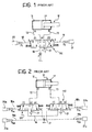
- a circuit of this type is illustrated in Figure 2 of the attached drawings, in which the same or corresponding components to those of Figure 1 have been indicated with the same reference numerals.
- a first, continuously adjustable directional control valve 120 is interposed between the first power line 12 and the supply and discharge lines 14 and 15 to put the power line 12 alternatively into communication with the supply line (working position 1) or with the discharge line (working position 2) or to close all three lines 12, 14 and 15 connected thereto (rest position 0).
- a second, continuously adjustable directional control valve 130 is interposed between the second power line 13 and the supply and discharge lines 14 and 15 to put the power line 13 alternatively into communication with the supply line (working position 1) or the discharge line (working position 2) or to close all three lines 13, 14 and 15 connected thereto (rest position 0).
- the adjustment of the directional control valve 120 from the rest position 0 towards the working positions 1 and 2 is controlled by a pair of pilot pressures p 1a and p 2a , which are produced by respective proportional solenoid valves 20a and 21a and act via respective pilot lines 18a and 19a in opposite directions on identical control surfaces S of the sliding member of this directional control valve.
- the adjustment of the directional control valve 130 from the rest position 0 towards the working positions 1 and 2 is controlled by a pair of pilot pressures p 1b and p 2b , which are produced by respective proportional solenoid valves 20b and 21b and act via respective pilot lines 18b and 19b in opposite directions on identical control surfaces S of the sliding member of this directional control valve.
- This arrangement makes it possible to control the position of the two sliding members of the directional control valves independently of one another, and therefore to control the supply flow area and the discharge flow area also independently of one another, but has the disadvantage of requiring the use of four solenoid valves for the control of the two sliding members, with the obvious consequence of a high cost.
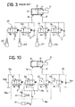
- a further known solution illustrated in Figure 3, provides for the use of four two-way, two-position, continuously adjustable directional control valves with a first pair of directional control valves 121 and 122 interposed between the first power line 12 (port A) and respectively, a supply line 14 (pump P) or a discharge line 15 (reservoir T), and a second pair of directional control valves 131 and 132 interposed between the second power line 13 (port B) and, respectively, the supply line 14 or discharge line 15.
- Each directional control valve is of the normally-closed type and is controllable by a pilot pressure generated by a respective solenoid valve 221, 222, 231, 232.
- control circuit has the disadvantage of requiring four solenoid valves to pilot the directional control valves.
- the object of the invention is to provide a circuit for the control of a double-acting fluid pressure actuator which enables to control the supply and discharge flow areas through the two ports of the actuator independently of one another, whilst nevertheless using a smaller number of pilot pressures and, therefore, of solenoid valves intended to generate those pressures, than the prior art.
- a control circuit intended to control the movement of a double-acting actuator 10
- first and second directional control valves 120 and 130 with continuously adjustable sliding member which valves are connected on one side with a first power line 12 associated to a port A of the actuator and with a second power line 13 associated to a port B of the actuator, respectively, and on the other side both with a supply line 14 connected to a pump P and with a discharge line 15 connected to a reservoir T.
- Each directional control valve 120, 130 can achieve:
- the shift from the rest condition 0 to either of the working positions 1, 2 can be adjusted so as to vary the supply and discharge fluid flow areas A P and A T , respectively.
- a pair of solenoid valves 20 and 21 of proportional type are arranged to generate a pair of pilot pressures p 1 and p 2 , which are supplied to the sliding members of the directional control valves 120 and 130 via respective pilot lines 18 and 19, each of which is split into a first pilot line 18a and 19a, respectively, associated to the first directional control valve 120 and a second pilot line 18b and 19b, respectively, associated to the second directional control valve 130.
- the pilot pressure p 1 generated by the solenoid valve 20 acts via the pilot line 18a on a control surface s of the sliding member of the first directional control valve 120 to move this sliding member into the working position 1, and via the pilot line 18b on a control surface S of the sliding member of the second directional control valve 130 (with S > s) to move this sliding member into the working position 2.
- the pilot pressure p 2 generated by the solenoid valve 21 acts via the pilot line 19a on a control surface S of the sliding member of the first directional control valve 120 to move this sliding member into the working position 2, and via the pilot line 19b on a control surface s of the sliding member of the second directional control valve 130 to move this sliding member into the working position 1.
- the directional control valves 120 and 130 are shifted into the working positions 1 and 2, respectively.
- the power line 12 therefore receives fluid through the first directional control valve 120 from the supply line 14 and can supply the rear chamber 16 of the actuator 10 through the port A.
- the power line 13 is put into communication with the discharge line 15, whereby the actuator 10 can discharge fluid from the front chamber 17 through the port B. The rod of the actuator 10 is thus caused to extend.
- the circuit is likewise able to assume a so-called floating condition in which both the directional control valves 120, 130 are in the working position 2 wherein they connect both the ports A and B of the actuator 10 to the discharge and therefore allow the free movement under load of the actuator rod.
- This operating condition can be achieved, for example, by generating pilot pressures p 1 and p 2 equal to one another, by virtue of the fact that each pressure acts on different control surfaces on the two sliding members.
- both the pilot pressures P 1 and p 2 at 0 by deactivating the solenoid valves 20 and 21 in such a way that both the directional control valves 120 and 130 are brought back into the rest position 0 and the power lines 12 and 13 which communicate with the ports A and B of the actuator are thus closed.
- control circuit of the present invention enables an independent adjustment of the two flow areas for the working fluid which is supplied or discharged by the power lines 12 and 13 as a result of the movement of the sliding members of the two directional control valves.
- the fluid flow area to the associated power line 12, 13 will be indicated A P when the line is connected to the supply, and the fluid flow area from the associated power line 12, 13 will be indicated A T when the line is connected to the discharge.
- the opening characteristics of the sliding members of the two directional control valves shown in Figure 5 define the variation of the resultant force on each sliding member as a function of the flow area, this latter being expressed as a percentage with respect to the maximum area (corresponding to the condition in which the port is completely open).
- the two sliding members have identical characteristics in which the following three sections can be noted:
- first operating condition F1 in which the first power line 12 (port A) is connected with the supply line 14 and the supply fluid flow area A P can be varied, whilst the second power line 13 (port B) is kept close, it is necessary to adjust the force F a on the sliding member of the first directional control valve 120 along the first section of the associated characteristic and the force F b on the sliding member of the second directional control valve 130 along the second section of the associated characteristic.
- the working condition F1 is therefore defined by the system of inequalities:
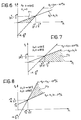
- figure 6 there is illustrated in broken outline a region ⁇ 1 of the p 1 -p 2 plane of the pilot pressures of the directional control valves, corresponding to the graphic solution of the above system.
- the operating condition F2 is therefore defined by the system of inequalities:
- Figure 7 there is illustrated in broken outline a region ⁇ 2 of the p 1 -p 2 plane of the pilot pressures of the directional control valves, corresponding to the graphic solution of the system of inequalities (9) and (10).
- the operating condition F3 is therefore defined by the system of inequalities:
- Figure 8 there is illustrated in broken outline a region ⁇ 3 of the p 1 -p 2 plane of the pilot pressures of the directional control valves, corresponding to the graphic solution of the system of inequalities (13) and (14).
- FIG 9 the three regions ⁇ 1 , ⁇ 2 and ⁇ 3 defined above are shown altogether, as well as two further regions ⁇ 1 ' and ⁇ 2 ' corresponding to two further operating conditions F1' and F2', respectively, which are symmetrical with respect to the conditions F1 and F2, that is, they differ from the latter conditions in that the ports A and B are a discharge port and a supply port, respectively, rather than a supply port and a discharge port. Due to the symmetry of the circuit and of the operating conditions F1' and F2', the regions ⁇ 1 ' and ⁇ 2 ' are symmetrical to the regions ⁇ 1 and ⁇ 2 with respect to the principal diagonal of the p 1 -p 2 plane.
- the characteristic of symmetry of the circuit is certainly advantageous, but not essential, for applying the present invention, and therefore the invention also encompasses the case of directional control valves with sliding members having operating characteristics different from one another.
- the invention is to be intended as relating also to the case of two directional control valves the sliding members of which have different operating characteristics from those described above.
- the first two directional control valves 121 and 122 are associated with the first power line 12 connected to the port A of the actuator 10 and control the connection of this power line with the supply (pump P) and the discharge (reservoir T), respectively.
- the second two directional control valves 131 and 132 are associated with the second power line 13 connected to the port B and control the connection of this power line with the supply (pump P) and with the discharge (reservoir T), respectively.
- the first and fourth directional control valves 121 and 132 are both controlled by a first pilot pressure p 1 generated by a first solenoid valve 20 and transmitted via a first pair of pilot lines 18a and 18b to the sliding members of the directional control valves 121 and 132, respectively.
- the second and third directional control valves 122 and 131 are both controlled by a second pilot pressure p 2 generated by a second solenoid valve 21 and transmitted via a second pair of pilot lines 19a and 19b to the sliding members of directional control valves 122 and 131, respectively.
- the first solenoid valve 20 thus controls, by means of the pilot pressure p 1 , the connection of the first power line 12 with the supply and of the second power line 13 with the discharge, whilst the second solenoid valve 21 controls, by means of the pilot pressure p 2 , the connection of the first power line 12 with the discharge and of the second power line 13 with the supply.
- the fluid flow area A can be adjusted between a nil value and a maximum value.
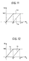
- the springs of the first and third directional control valves 121 and 131 have a greater preload than those of the remaining two directional control valves 122 and 132, as can be inferred by the opening characteristics of the four directional control valves shown in Figures 11 and 12.
- the first directional control valve 121 remains closed and the fourth directional control valve 132 regulates the connection of the second power line 13 with the discharge.
- the fourth directional control valve 132 is fully open and the first directional control valve 121 regulates the connection of the first power line 12 with the supply.
- both the directional control valves 121 and 132 are fully open.
- the third directional control valve 131 remains closed and the second directional control valve 122 regulates the connection of the first power line 12 with the reservoir.
- the second directional control valve 122 is fully open and the third directional control valve 131 regulates the connection of the third power line 13 with the supply.
- both the directional control valves 122 and 131 are fully open.
- the directional control valves 121 and 132 respectively, control the connection of the actuator port A with the supply and of the actuator port B with the discharge.
- the first solenoid valve 20 When a resisting load acts upon the actuator rod, it is necessary for the first solenoid valve 20 to generate a pilot pressure value greater than p 1 *, whereby the first directional control valve 121 puts the port A into communication with the supply.
- the first solenoid valve 20 when a pulling load acts upon the actuator rod, it is necessary for the first solenoid valve 20 to generate a pilot pressure value less than p 1 *, whereby only the fourth directional control valve 132 controlling the discharge port is kept open.
- a further power line 15a in which a first check valve 22a is arranged which allows fluid to flow only from the reservoir to the actuator.
- the directional control valves 122 and 131 respectively, control the connection of the actuator port A with the discharge and of the actuator port B with the supply.
- the second solenoid valve 21 must generate a pilot pressure value greater than p 2 * when a resisting load occurs and less than p 2 * when a pulling load occurs.
- the floating operating condition can be achieved by generating pilot pressure signals p 1 and p 2 lower than p 1 * and p 2 *, respectively, in such a way that the directional control valves 121 and 131 associated with the supply P are closed and only the directional control valves 122 and 132 associated with the discharge T are open.
Landscapes
- Engineering & Computer Science (AREA)
- Physics & Mathematics (AREA)
- Fluid Mechanics (AREA)
- Mechanical Engineering (AREA)
- General Engineering & Computer Science (AREA)
- Fluid-Pressure Circuits (AREA)
Abstract
The circuit comprises first and second power lines (12, 13) connected to a port (A) of a first chamber (16) and to the port (B) of a second chamber (17) of an actuator (10), respectively; a supply line (14) and a discharge line (15) connected to a supply source (P) and to a discharge reservoir (T); a first sliding member valve (120) capable of connecting the first power line (12) to the supply and discharge lines (14, 15) under the control of pilot pressures (p1, p2) transmitted to the sliding member valve (120) by a first pair of pilot lines (18a, 19a); and a second sliding member valve (130) capable of connecting the second power line (13) with the supply and discharge lines (14, 15) under the control of pilot pressures (p1, p2) transmitted to the sliding member valve (130) by a second pair of pilot lines (18b, 19b). The one line (18a) of the first pair of pilot lines (18a, 19a) and the one line (18b) of the second pair of pilot lines (18b, 19b) transmit the same first pilot pressure signal (p1); the other line (19a) of the first pair of pilot lines (18a, 19a) and the other line (19b) of the second pair of pilot lines (18b, 19b) transmit the same second pilot pressure signal (p2), whereby the actuator (10) can be controlled by only two pilot pressures (p1, p2). <IMAGE>
Description
The present invention relates to a circuit for the control of
a double-acting fluid pressure actuator. According to a first
aspect of the invention, the control circuit comprises two
three-way, three-position, continuously adjustable
directional control valves, each controllable by a pair of
pilot pressures. According to a further aspect of the
invention, the control circuit comprises four two-way, two-position
directional control valves with continuously
adjustable sliding members, each controllable by a respective
pilot pressure.
In order to make it easier to read and understand the
description of the invention, terms such as "circuit",
"actuator" or "directional control valve" will hereinafter be
used without adding the adjectives "hydraulic" or "pneumatic"
thereto, it being apparent that the invention relates to
hydraulic or pneumatic circuits, that is, circuits which
exploit a working fluid.
To control the movement of a double-acting actuator it is
known for example to use a four-way, three-position
directional control valve controllable by a pair of pilot
pressures.
Referring to Figure 1 of the attached drawings, a double-acting
actuator is generally indicated 10 and a four-way,
three-position, continuously adjustable directional control
valve is indicated 100.
The actuator 10 comprises a rear chamber 16 connectable to
the outside through a port A, and a front chamber 17
connectable to the outside through a port B. The directional
control valve 100 is interposed between a pair of power lines
12 and 13 connected to the port A and the port B of the
actuator 10, respectively, and a pair of power lines 14 and
15, that is, a supply line and a discharge line, connected to
a pump P and to a reservoir T, respectively. A pair of
proportional solenoid valves 20 and 21 are arranged to
generate respective pilot pressures p1 and p2, which via
respective pilot lines 18 and 19 act in opposite directions
on identical control surfaces S of the sliding member of the
directional control valve 100 to move this latter from a rest
position 0 to one of two working positions 1 and 2.
The directional control valve 100 is of the normally-closed
type, that is to say in the rest position 0 it closes both
the power lines 12 and 13 connected to the actuator 10 and
the supply and discharge lines 14 and 15. In this condition
the actuator 10 is therefore locked in a fixed position,
since neither of its chambers 16 and 17 is connected either
to the pump P or to the reservoir T.
The operation of a directional control valve of this type is
known to the man skilled in the art and therefore will not be
described in detail. What is of interest to show here is that
the displacement of the sliding member of the directional
control valve 100 from the rest position 0 to one of the two
working positions 1 and 2 takes place in a continuous and
adjustable manner, whereby the flow areas AP and AT of the
working fluid in the supply direction through one of the
ports of the actuator 10 and in the discharge direction from
the other port, respectively, vary between a nil value and a
maximum value as a function of the instantaneous position of
the sliding member. The opening characteristic of the fluid
flow cross areas, that is to say the law of variation of
these areas as a function of the position of the sliding
member, is established at the design stage of the directional
control valve to satisfy a series of functional requirements
such as, for example, the control of the flow rate value, the
reduction of leakage, the rapidity of port and the protection
against possible overpressures in the circuit.
A directional control valve of the above-described type is
not, however, able to control the supply flow area AP and the
discharge flow area AT independently from one another, and
therefore provides a single degree of freedom for the control
of the movement of the actuator, since each position of the
sliding member corresponds to a single predetermined value of
the ratio AP/AT between the supply and discharge flow areas.
In order to have a further degree of freedom available, it is
known to use a control circuit comprising a pair of three-way,
three-position, continuously adjustable directional
control valves. A circuit of this type is illustrated in
Figure 2 of the attached drawings, in which the same or
corresponding components to those of Figure 1 have been
indicated with the same reference numerals. With reference to
Figure 2, a first, continuously adjustable directional
control valve 120 is interposed between the first power line
12 and the supply and discharge lines 14 and 15 to put the
power line 12 alternatively into communication with the
supply line (working position 1) or with the discharge line
(working position 2) or to close all three lines 12, 14 and
15 connected thereto (rest position 0). A second,
continuously adjustable directional control valve 130 is
interposed between the second power line 13 and the supply
and discharge lines 14 and 15 to put the power line 13
alternatively into communication with the supply line
(working position 1) or the discharge line (working position
2) or to close all three lines 13, 14 and 15 connected
thereto (rest position 0).
The adjustment of the directional control valve 120 from the
rest position 0 towards the working positions 1 and 2 is
controlled by a pair of pilot pressures p1a and p2a, which are
produced by respective proportional solenoid valves 20a and
21a and act via respective pilot lines 18a and 19a in
opposite directions on identical control surfaces S of the
sliding member of this directional control valve. In the same
way, the adjustment of the directional control valve 130 from
the rest position 0 towards the working positions 1 and 2 is
controlled by a pair of pilot pressures p1b and p2b, which are
produced by respective proportional solenoid valves 20b and
21b and act via respective pilot lines 18b and 19b in
opposite directions on identical control surfaces S of the
sliding member of this directional control valve.
This arrangement makes it possible to control the position of
the two sliding members of the directional control valves
independently of one another, and therefore to control the
supply flow area and the discharge flow area also
independently of one another, but has the disadvantage of
requiring the use of four solenoid valves for the control of
the two sliding members, with the obvious consequence of a
high cost.
A further known solution, illustrated in Figure 3, provides
for the use of four two-way, two-position, continuously
adjustable directional control valves with a first pair of
directional control valves 121 and 122 interposed between the
first power line 12 (port A) and respectively, a supply line
14 (pump P) or a discharge line 15 (reservoir T), and a
second pair of directional control valves 131 and 132
interposed between the second power line 13 (port B) and,
respectively, the supply line 14 or discharge line 15. Each
directional control valve is of the normally-closed type and
is controllable by a pilot pressure generated by a respective
solenoid valve 221, 222, 231, 232.
In this case, too, the control circuit has the disadvantage
of requiring four solenoid valves to pilot the directional
control valves.
The object of the invention is to provide a circuit for the
control of a double-acting fluid pressure actuator which
enables to control the supply and discharge flow areas
through the two ports of the actuator independently of one
another, whilst nevertheless using a smaller number of pilot
pressures and, therefore, of solenoid valves intended to
generate those pressures, than the prior art.
This object is achieved according to the invention by virtue
of a control circuit having the characteristics defined in
the characterising part of independent Claim 1. Preferred
embodiments of the invention are defined in the dependent
claims.
The characteristics and advantages of the invention will
become apparent from the detailed description which follows,
given purely by way of non-limitative example, with reference
to the attached drawings, in which:
In the following description of the two embodiments of the
invention there will be illustrated specifically only the
components and features necessary for understanding of the
invention, it being clear that for anything not expressly
described or mentioned reference will be made to the prior
art discussed above, and in particular to the circuit schemes
of Figures 2 and 3.
Referring first to the scheme of Figure 4, where components
identical or corresponding to those of Figure 2 (prior art)
have been indicated with the same reference numerals, a
control circuit according to the invention, intended to
control the movement of a double-acting actuator 10,
comprises first and second directional control valves 120 and
130 with continuously adjustable sliding member, which valves
are connected on one side with a first power line 12
associated to a port A of the actuator and with a second
power line 13 associated to a port B of the actuator,
respectively, and on the other side both with a supply line
14 connected to a pump P and with a discharge line 15
connected to a reservoir T.
Each directional control valve 120, 130 can achieve:
Obviously, as far as continuously adjustable directional
control valves are concerned, the shift from the rest
condition 0 to either of the working positions 1, 2 can be
adjusted so as to vary the supply and discharge fluid flow
areas AP and AT, respectively.
A pair of solenoid valves 20 and 21 of proportional type are
arranged to generate a pair of pilot pressures p1 and p2,
which are supplied to the sliding members of the directional
control valves 120 and 130 via respective pilot lines 18 and
19, each of which is split into a first pilot line 18a and
19a, respectively, associated to the first directional
control valve 120 and a second pilot line 18b and 19b,
respectively, associated to the second directional control
valve 130.
In particular, the pilot pressure p1 generated by the
solenoid valve 20 acts via the pilot line 18a on a control
surface s of the sliding member of the first directional
control valve 120 to move this sliding member into the
working position 1, and via the pilot line 18b on a control
surface S of the sliding member of the second directional
control valve 130 (with S > s) to move this sliding member
into the working position 2. The pilot pressure p2 generated
by the solenoid valve 21 acts via the pilot line 19a on a
control surface S of the sliding member of the first
directional control valve 120 to move this sliding member
into the working position 2, and via the pilot line 19b on a
control surface s of the sliding member of the second
directional control valve 130 to move this sliding member
into the working position 1.
Where only the pilot pressure p1 is present and the pressure
p2 is set at 0, the directional control valves 120 and 130
are shifted into the working positions 1 and 2, respectively.
The power line 12 therefore receives fluid through the first
directional control valve 120 from the supply line 14 and can
supply the rear chamber 16 of the actuator 10 through the
port A. On the other hand, the power line 13 is put into
communication with the discharge line 15, whereby the
actuator 10 can discharge fluid from the front chamber 17
through the port B. The rod of the actuator 10 is thus caused
to extend.
On the other hand, where only the pilot pressure p2 is
present and the pressure p1 is set at 0, the ports B and A of
the actuator 10 are connected with the supply line 14 and the
discharge line 15, respectively, thereby causing the actuator
rod to retract.
The circuit is likewise able to assume a so-called floating
condition in which both the directional control valves 120,
130 are in the working position 2 wherein they connect both
the ports A and B of the actuator 10 to the discharge and
therefore allow the free movement under load of the actuator
rod. This operating condition can be achieved, for example,
by generating pilot pressures p1 and p2 equal to one another,
by virtue of the fact that each pressure acts on different
control surfaces on the two sliding members.
Finally, to lock the rod of the actuator 10 in position it is
sufficient to set both the pilot pressures P1 and p2 at 0 by
deactivating the solenoid valves 20 and 21 in such a way that
both the directional control valves 120 and 130 are brought
back into the rest position 0 and the power lines 12 and 13
which communicate with the ports A and B of the actuator are
thus closed.
It will now be illustrated how the control circuit of the
present invention enables an independent adjustment of the
two flow areas for the working fluid which is supplied or
discharged by the power lines 12 and 13 as a result of the
movement of the sliding members of the two directional
control valves. In conformity with the symbols used above,
for each of the sliding members of the directional control
valves 120, 130 the fluid flow area to the associated power
line 12, 13 will be indicated AP when the line is connected
to the supply, and the fluid flow area from the associated
power line 12, 13 will be indicated AT when the line is
connected to the discharge.
Indicating Fa the resultant force on the sliding member of
the first directional control valve 120 and Fb the resultant
force on the sliding member of the second directional control
valve 130, the static equilibrium equations for the two
sliding members are:
The opening characteristics of the sliding members of the two
directional control valves shown in Figure 5 define the
variation of the resultant force on each sliding member as a
function of the flow area, this latter being expressed as a
percentage with respect to the maximum area (corresponding to
the condition in which the port is completely open). In the
example under discussion, the two sliding members have
identical characteristics in which the following three
sections can be noted:
To provide a first operating condition F1, in which the first
power line 12 (port A) is connected with the supply line 14
and the supply fluid flow area AP can be varied, whilst the
second power line 13 (port B) is kept close, it is necessary
to adjust the force Fa on the sliding member of the first
directional control valve 120 along the first section of the
associated characteristic and the force Fb on the sliding
member of the second directional control valve 130 along the
second section of the associated characteristic.
The working condition F1 is therefore defined by the system
of inequalities:
Substituting in inequalities (3) and (4) the expressions (1)
and (2) of the forces Fa and Fb as a function of the pilot
pressures p1 and p2, the system of inequalities becomes:
In figure 6 there is illustrated in broken outline a region
σ1 of the p1-p2 plane of the pilot pressures of the
directional control valves, corresponding to the graphic
solution of the above system.
Therefore, in order to bring the circuit into the operating
condition F1 defined above it is necessary to control the two
solenoid valves 20 and 21 in such a way that they generate a
pair of pilot pressures p1 and p2 the values of which satisfy
the system of inequalities (5) and (6), that is to say they
lie between limits graphically identified by the region σ1 of
the plane p1-p2.
To achieve a second operating condition F2, in which the
power lines 12 and 13 are connected with the supply line 14
and the discharge line 15, respectively, and both the supply
fluid flow area AP and the discharge fluid flow area AT can
be varied, it is necessary to adjust the force Fa on the
sliding member of the first directional control valve 120
along the first section of the associated characteristic and
the force Fb on the sliding member of the second directional
control valve 130 along the third section of the associated
characteristic.
The operating condition F2 is therefore defined by the system
of inequalities:
By substituting into inequalities (7) and (8) the expressions
(1) and (2) of the forces Fa and Fb as a function of the
pilot pressures p1 and p2, and solving with respect to p2, the
system of inequalities becomes:
In Figure 7 there is illustrated in broken outline a region
σ2 of the p1-p2 plane of the pilot pressures of the
directional control valves, corresponding to the graphic
solution of the system of inequalities (9) and (10).
To achieve a third operating condition F3, in which both the
power lines 12 and 13 are connected to the reservoir T
through the discharge line 15 and the discharge fluid flow
area AT can be varied for both the lines, it is necessary to
adjust both the force Fa and the force Fb along the third
section of the characteristics of the respective sliding
members.
The operating condition F3 is therefore defined by the system
of inequalities:
By substituting into the inequalities (11) and (12) the
expressions (1) and (2) of the forces Fa and Fb as a function
of the pilot pressures p1 and p2 and solving with respect to
p2, the system of inequalities becomes:
In Figure 8 there is illustrated in broken outline a region
σ3 of the p1-p2 plane of the pilot pressures of the
directional control valves, corresponding to the graphic
solution of the system of inequalities (13) and (14).
In Figure 9 the three regions σ1, σ2 and σ3 defined above are
shown altogether, as well as two further regions σ1' and σ2'
corresponding to two further operating conditions F1' and
F2', respectively, which are symmetrical with respect to the
conditions F1 and F2, that is, they differ from the latter
conditions in that the ports A and B are a discharge port and
a supply port, respectively, rather than a supply port and a
discharge port. Due to the symmetry of the circuit and of the
operating conditions F1' and F2', the regions σ1' and σ2' are
symmetrical to the regions σ1 and σ2 with respect to the
principal diagonal of the p1-p2 plane.
The characteristic of symmetry of the circuit is certainly
advantageous, but not essential, for applying the present
invention, and therefore the invention also encompasses the
case of directional control valves with sliding members
having operating characteristics different from one another.
In the same way, the invention is to be intended as relating
also to the case of two directional control valves the
sliding members of which have different operating
characteristics from those described above. Finally, although
reference has been made so far to an arrangement with two
directional control valves each having a single sliding
member, it is clear that the invention can be applied equally
to a single directional control valve provided with two
continuously adjustable sliding members.
Referring now to the circuit scheme of Figure 10, where
components identical or corresponding to those of Figure 3
(prior art) have been indicated with the same reference
numerals, in order to control the movement of a double-acting
actuator 10 there are provided four two-way, two-position,
normally-closed directional control valves with continuously
adjustable sliding member, indicated 121, 122, 131 and 132,
respectively.
The first two directional control valves 121 and 122 are
associated with the first power line 12 connected to the port
A of the actuator 10 and control the connection of this power
line with the supply (pump P) and the discharge (reservoir
T), respectively. The second two directional control valves
131 and 132 are associated with the second power line 13
connected to the port B and control the connection of this
power line with the supply (pump P) and with the discharge
(reservoir T), respectively.
The first and fourth directional control valves 121 and 132
are both controlled by a first pilot pressure p1 generated by
a first solenoid valve 20 and transmitted via a first pair of
pilot lines 18a and 18b to the sliding members of the
directional control valves 121 and 132, respectively. The
second and third directional control valves 122 and 131 are
both controlled by a second pilot pressure p2 generated by a
second solenoid valve 21 and transmitted via a second pair of
pilot lines 19a and 19b to the sliding members of directional
control valves 122 and 131, respectively.
The first solenoid valve 20 thus controls, by means of the
pilot pressure p1, the connection of the first power line 12
with the supply and of the second power line 13 with the
discharge, whilst the second solenoid valve 21 controls, by
means of the pilot pressure p2, the connection of the first
power line 12 with the discharge and of the second power line
13 with the supply.
As far as directional control valves with continuously
adjustable sliding members are concerned, that is to say,
valves in which the shift from the rest position (closed
valve) to the working position (open valve) is controlled by
the equilibrium between the pilot pressure acting on the
sliding member of the directional control valve and the
biasing action of a spring which tends to bring the sliding
member back into the rest position, the fluid flow area A can
be adjusted between a nil value and a maximum value.
In particular, in the embodiment described here, the springs
of the first and third directional control valves 121 and 131
have a greater preload than those of the remaining two
directional control valves 122 and 132, as can be inferred by
the opening characteristics of the four directional control
valves shown in Figures 11 and 12.
With reference first to Figure 11, for values of the first
pilot pressure p1 lying between 0 and a first limit value
p1*, the first directional control valve 121 remains closed
and the fourth directional control valve 132 regulates the
connection of the second power line 13 with the discharge.
For values lying between the first limit value p1* and a
second limit value p1**, the fourth directional control valve
132 is fully open and the first directional control valve 121
regulates the connection of the first power line 12 with the
supply. Above the value p1** both the directional control
valves 121 and 132 are fully open.
Referring now to Figure 12, for values of the second pilot
pressure p2 lying between 0 and a first limit value p2*, the
third directional control valve 131 remains closed and the
second directional control valve 122 regulates the connection
of the first power line 12 with the reservoir. For values
lying between the first limit value p2* and a second limit
value p2**, the second directional control valve 122 is fully
open and the third directional control valve 131 regulates
the connection of the third power line 13 with the supply.
Above the value p2** both the directional control valves 122
and 131 are fully open.
Some operating conditions of the circuit according to this
further embodiment of the invention will now be described
with reference to Figures 10 to 12.
In order to control the extension of the rod of the actuator
10, only the first pilot pressure p1 is varied, while the
second pilot pressure p2 is kept at 0. In this way, in fact,
the directional control valves 121 and 132, respectively,
control the connection of the actuator port A with the supply
and of the actuator port B with the discharge.
When a resisting load acts upon the actuator rod, it is
necessary for the first solenoid valve 20 to generate a pilot
pressure value greater than p1*, whereby the first
directional control valve 121 puts the port A into
communication with the supply. The extension speed of the rod
can be adjusted, as a function of the pilot pressure p1,
between a nil value (for p1 = p1*) and a maximum value (for
p1* ≥ p1**).
On the other hand, when a pulling load acts upon the actuator
rod, it is necessary for the first solenoid valve 20 to
generate a pilot pressure value less than p1*, whereby only
the fourth directional control valve 132 controlling the
discharge port is kept open. In this case, also, the
extension speed of the rod can be adjusted, as a function of
the pilot pressure p1, between a nil value (for p1 = 0) and a
maximum value (for p1 = p1*).
In order to avoid cavitation phenomena in case of pulling
load, there is provided between the actuator port A and the
reservoir T a further power line 15a in which a first check
valve 22a is arranged which allows fluid to flow only from
the reservoir to the actuator.
In order to control retraction of the rod of the actuator 10,
only the second pilot pressure p2 is varied, while the first
pilot pressure p1 is kept at 0. In this way, in fact, the
directional control valves 122 and 131, respectively, control
the connection of the actuator port A with the discharge and
of the actuator port B with the supply. In a similar manner
to what has been explained above in case of extension of the
rod, the second solenoid valve 21 must generate a pilot
pressure value greater than p2* when a resisting load occurs
and less than p2* when a pulling load occurs. Moreover, in
order to avoid cavitation phenomena in case of pulling load,
there is provided between the actuator port B and the
reservoir T a further power line 15b in which a second check
valve 22b is arranged which allows fluid to flow only from
the reservoir to the actuator.
Finally, the floating operating condition can be achieved by
generating pilot pressure signals p1 and p2 lower than p1* and
p2*, respectively, in such a way that the directional control
valves 121 and 131 associated with the supply P are closed
and only the directional control valves 122 and 132
associated with the discharge T are open.
Naturally, the principle of the invention remaining
unchanged, embodiments and details of construction can be
widely varied with respect to those described and illustrated
purely by way of non-limitative example.
Claims (11)
- An electrohydraulic circuit for control of a fluid pressure actuator (10) having first and second chambers (16, 17) each provided with a respective port (A, B); the circuit comprisingcharacterised in that the one line (18a) of the first pair of pilot lines (18a, 19a) and the one line (18b) of the second pair of pilot lines (18b, 19b) are arranged to transmit the same first pilot pressure signal (p1), and in that the other line (19a) of the first pair of pilot lines (18a, 19a) and the other line (19b) of the second pair of pilot lines (18b, 19b) are arranged to transmit the same second pilot pressure signal (p2), whereby the actuator (10) can be controlled by means of the first and second pilot pressure signals (p1, p2) .first and second power lines (12, 13) connected to the port (A) of the first chamber (16) and to the port (B) of the second chamber (17) of the actuator (10), respectively;at least one supply line (14) and at least one discharge line (15) connected to a supply source (P) and to a discharge reservoir (T), respectively;at least one first sliding member valve (120; 121, 122) interposed between the first power line (12) and the supply and discharge lines (14, 15) and capable of putting the port (A) of the first chamber of the actuator (10) into communication with the supply (P) or with the discharge (T) under the control of pilot pressure signals (p1, p2) transmitted to the said at least one first sliding member valve by a first pair of pilot lines (18a, 19a); andat least one second sliding member valve (130; 131, 132) interposed between the second power line (13) and the supply and discharge lines (14, 15) and capable of putting the port (B) of the second chamber (17) of the actuator (10) into communication with the supply (P) or with the discharge (T) under the control of pilot pressure signals (p1, p2) transmitted to the said at least one second sliding member valve by a second pair of pilot lines (18b, 19b) ;
- A control circuit according to Claim 1, comprising a first, continuously adjustable sliding member valve (120) interposed between the first power line (12) and the supply and discharge lines (14, 15) and a second, continuously adjustable sliding member valve (130) interposed between the second power line (13) and the supply and discharge lines (14, 15), characterised in that each of the first and second sliding member valves (120, 130) has first and second control surfaces (s, S), different from one another, on each of which a respective pilot pressure signal (p1, p2) acts.
- A control circuit according to Claim 2, characterised in that the first control surface (s) of the first sliding member valve (120) and the second control surface (S) of the second sliding member valve (130) are both subject to the first pilot pressure signal (p1), in such a way that the first signal tends to shift the first sliding member valve (120) into a first working position (1) and the second sliding member valve (130) into a second working position (2); and in that the second control surface (S) of the first sliding member valve (120) and the first control surface (s) of the second sliding member valve (130) are both subject to the second pilot pressure signal (p2), in such a way that the second signal tends to shift the first sliding member valve (120) into a second working position (2) and the second sliding member valve (130) into a first working position (1); wherein in the first working position (1) the two sliding member valves (120, 130) put the associated first or second power line (12, 13) into communication with the supply line (14) and close the discharge line (15), whilst in the second working position (2) the two sliding member valves (120, 130) put the associated first or second power line (12, 13) into communication with the discharge line (15) and close the supply line (14).
- A control circuit according to Claim 3, characterised in that the first control surfaces (s) of the first and second sliding member valves (120, 130) are smaller than the second control surfaces (S).
- A control circuit according to Claim 4, characterised in that each of the two sliding member valves (120, 130) is also capable of assuming a rest position (0) in which the sliding member valve closes all the lines (12, 13, 14, 15) connected thereto.
- A control circuit according to Claim 4, characterised in that each of the two sliding member valves (120, 130) has an opening characteristic such that the sliding member valve can be shifted into the first working position (1) under a resultant force (Fa, Fb) of given direction which increases as the fluid flow area (Ap) from the supply (P) increases, and into the second working position (2) under an opposite resultant force (Fa, Fb) which increases as the fluid flow area (AT) towards the discharge (T) increases.
- A control circuit according to Claim 1, comprising a first pair of continuously adjustable sliding member valves (121, 122) interposed between the first power line (12) and the supply and discharge lines (14, 15), respectively, and a second pair of continuously adjustable sliding member valves (131, 132) interposed between the second power line (13) and the supply and discharge lines (14, 15), respectively, characterised in that the sliding member valves are of the two-way, two-position type.
- A control circuit according to Claim 7, characterised in that the sliding member valves (121, 122, 131, 132) are of the normally-closed type.
- A control circuit according to Claim 8, characterised in that in each pair of sliding member valves (121, 132; 122, 131) controlled by the same pilot pressure signal (p1, p2), the sliding member valve (121; 131) associated with the supply (P) is arranged to shift from the closed position to the open position under the effect of a pilot pressure greater than that necessary to shift the sliding member valve (122; 132) associated with the discharge (T).
- A control circuit according to Claim 7, characterised in that it comprises also a further pair of power lines (15a, 15b) which connect the first and second chambers (16, 17) of the actuator (10) to the discharge (T) and are each provided with a respective check valve (22a, 22b) arranged to prevent flow from the respective chamber (16, 17) of the actuator (10) to the discharge (T).
- A control circuit according to Claim 1, characterised in that each of the two pilot pressure signals (p1, p2) is generated by a solenoid valve (20, 21).
Applications Claiming Priority (2)
| Application Number | Priority Date | Filing Date | Title |
|---|---|---|---|
| IT2002TO000440A ITTO20020440A1 (en) | 2002-05-23 | 2002-05-23 | ELECTROHYDRAULIC CIRCUIT FOR THE CONTROL OF A FLUID ACTUATOR. |
| ITTO20020440 | 2002-05-23 |
Publications (1)
| Publication Number | Publication Date |
|---|---|
| EP1365158A2 true EP1365158A2 (en) | 2003-11-26 |
Family
ID=27639108
Family Applications (1)
| Application Number | Title | Priority Date | Filing Date |
|---|---|---|---|
| EP03011601A Withdrawn EP1365158A2 (en) | 2002-05-23 | 2003-05-22 | An electrohydraulic circuit for control of a fluid pressure actuator |
Country Status (3)
| Country | Link |
|---|---|
| US (1) | US20040011192A1 (en) |
| EP (1) | EP1365158A2 (en) |
| IT (1) | ITTO20020440A1 (en) |
Cited By (1)
| Publication number | Priority date | Publication date | Assignee | Title |
|---|---|---|---|---|
| EP1700728A3 (en) * | 2005-03-08 | 2009-09-09 | Robert Bosch Gmbh | Hydraulic actuation system for a convertible car roof |
Families Citing this family (13)
| Publication number | Priority date | Publication date | Assignee | Title |
|---|---|---|---|---|
| EP2201277A4 (en) * | 2007-09-27 | 2017-10-18 | Kmatic APS | Valve actuator system |
| US9273796B2 (en) | 2007-09-27 | 2016-03-01 | Kmatic Aps | Valve actuator system |
| US9163619B2 (en) * | 2010-09-17 | 2015-10-20 | Safoco, Inc. | Valve actuator control system and method of use |
| DE102013004437A1 (en) * | 2013-02-20 | 2014-08-21 | Robert Bosch Gmbh | Hydraulic safety and motion control system |
| CN105264149B (en) * | 2013-06-03 | 2017-12-22 | 沃尔沃建筑设备公司 | Method for the hydraulic system of engineering machinery and for controlling hydraulic system |
| US10563676B1 (en) * | 2014-06-23 | 2020-02-18 | Vecna Robotics, Inc. | Hydrosymbiosis |
| WO2016163058A1 (en) | 2015-04-07 | 2016-10-13 | 株式会社クボタ | Work machine hydraulic system and work machine provided with said hydraulic system |
| WO2017127678A1 (en) * | 2016-01-20 | 2017-07-27 | Nexmatix Llc | Four-way control valve for pneumatic charging and discharging of working vessel |
| DE102016206821A1 (en) * | 2016-04-21 | 2017-10-26 | Festo Ag & Co. Kg | Method for operating a valve device, valve device and data carrier with a computer program |
| US10337532B2 (en) | 2016-12-02 | 2019-07-02 | Caterpillar Inc. | Split spool valve |
| US11105347B2 (en) * | 2017-07-20 | 2021-08-31 | Eaton Intelligent Power Limited | Load-dependent hydraulic fluid flow control system |
| JP7523259B2 (en) * | 2020-06-19 | 2024-07-26 | 川崎重工業株式会社 | Hydraulic Drive System |
| JP7645088B2 (en) * | 2021-02-16 | 2025-03-13 | 株式会社小松製作所 | Boom control system for work machines |
Family Cites Families (4)
| Publication number | Priority date | Publication date | Assignee | Title |
|---|---|---|---|---|
| US3680588A (en) * | 1971-01-04 | 1972-08-01 | Caterpillar Tractor Co | High pressure implement hydraulic circuit |
| US4479678A (en) * | 1981-07-24 | 1984-10-30 | Sharp Robert M | Pneumatic valve |
| US4651625A (en) * | 1984-05-21 | 1987-03-24 | United Controls, Inc. | Pneumatic control assembly for a pneumatic cylinder |
| JPS61124702A (en) * | 1984-11-22 | 1986-06-12 | Komatsu Ltd | Hydraulic control device |
-
2002
- 2002-05-23 IT IT2002TO000440A patent/ITTO20020440A1/en unknown
-
2003
- 2003-05-22 US US10/442,990 patent/US20040011192A1/en not_active Abandoned
- 2003-05-22 EP EP03011601A patent/EP1365158A2/en not_active Withdrawn
Non-Patent Citations (1)
| Title |
|---|
| None |
Cited By (1)
| Publication number | Priority date | Publication date | Assignee | Title |
|---|---|---|---|---|
| EP1700728A3 (en) * | 2005-03-08 | 2009-09-09 | Robert Bosch Gmbh | Hydraulic actuation system for a convertible car roof |
Also Published As
| Publication number | Publication date |
|---|---|
| ITTO20020440A1 (en) | 2003-11-24 |
| US20040011192A1 (en) | 2004-01-22 |
| ITTO20020440A0 (en) | 2002-05-23 |
Similar Documents
| Publication | Publication Date | Title |
|---|---|---|
| EP0468944B1 (en) | An arrangement for controlling hydraulic motors | |
| US20040011192A1 (en) | Electrohydraulic circuit for control of a fluid pressure actuator | |
| US4201052A (en) | Power transmission | |
| US4250794A (en) | High pressure hydraulic system | |
| US4354420A (en) | Fluid motor control system providing speed change by combination of displacement and flow control | |
| US4418612A (en) | Power transmission | |
| US6502500B2 (en) | Hydraulic system for a work machine | |
| EP0251172B1 (en) | Hydraulic control system | |
| US4367624A (en) | Control system for hydraulic actuator | |
| GB2419195A (en) | Hydraulic valve arrangement for assisting regenerative working | |
| US7614336B2 (en) | Hydraulic system having augmented pressure compensation | |
| USRE38355E1 (en) | Electrohydraulic control device for double-acting consumer | |
| EP1482182A1 (en) | Hydraulic control valve assembly having dual directional spool valves with pilot operated check valves | |
| EP0160289A2 (en) | Hydraulic control system | |
| US6895852B2 (en) | Apparatus and method for providing reduced hydraulic flow to a plurality of actuatable devices in a pressure compensated hydraulic system | |
| US6161467A (en) | Fluid control system with regeneration | |
| US6186044B1 (en) | Fluid control system with float capability | |
| US20110030816A1 (en) | Control system for controlling a directional control valve | |
| EP0209019B1 (en) | Hydraulic control system | |
| US3467126A (en) | Hydraulic load compensating directional control valve | |
| US3847180A (en) | Low effort, proportional control valve | |
| US4606258A (en) | Self-pressurizing hydraulic control system | |
| US6293181B1 (en) | Control system providing a float condition for a hydraulic cylinder | |
| US6761027B2 (en) | Pressure-compensated hydraulic circuit with regeneration | |
| US5839885A (en) | Capacity control apparatus for a variable capacity hydraulic pump |
Legal Events
| Date | Code | Title | Description |
|---|---|---|---|
| PUAI | Public reference made under article 153(3) epc to a published international application that has entered the european phase |
Free format text: ORIGINAL CODE: 0009012 |
|
| AK | Designated contracting states |
Kind code of ref document: A2 Designated state(s): AT BE BG CH CY CZ DE DK EE ES FI FR GB GR HU IE IT LI LU MC NL PT RO SE SI SK TR |
|
| AX | Request for extension of the european patent |
Extension state: AL LT LV MK |
|
| STAA | Information on the status of an ep patent application or granted ep patent |
Free format text: STATUS: THE APPLICATION HAS BEEN WITHDRAWN |
|
| 18W | Application withdrawn |
Effective date: 20050816 |