EP1365154B1 - Counterrotatable booster compressor assembly for a gas turbine engine - Google Patents
Counterrotatable booster compressor assembly for a gas turbine engine Download PDFInfo
- Publication number
- EP1365154B1 EP1365154B1 EP03253260A EP03253260A EP1365154B1 EP 1365154 B1 EP1365154 B1 EP 1365154B1 EP 03253260 A EP03253260 A EP 03253260A EP 03253260 A EP03253260 A EP 03253260A EP 1365154 B1 EP1365154 B1 EP 1365154B1
- Authority
- EP
- European Patent Office
- Prior art keywords
- fan
- blade row
- compressor
- counterrotatable
- drive shaft
- Prior art date
- Legal status (The legal status is an assumption and is not a legal conclusion. Google has not performed a legal analysis and makes no representation as to the accuracy of the status listed.)
- Expired - Fee Related
Links
Images


Classifications
-
- F—MECHANICAL ENGINEERING; LIGHTING; HEATING; WEAPONS; BLASTING
- F01—MACHINES OR ENGINES IN GENERAL; ENGINE PLANTS IN GENERAL; STEAM ENGINES
- F01D—NON-POSITIVE DISPLACEMENT MACHINES OR ENGINES, e.g. STEAM TURBINES
- F01D5/00—Blades; Blade-carrying members; Heating, heat-insulating, cooling or antivibration means on the blades or the members
- F01D5/02—Blade-carrying members, e.g. rotors
- F01D5/022—Blade-carrying members, e.g. rotors with concentric rows of axial blades
-
- F—MECHANICAL ENGINEERING; LIGHTING; HEATING; WEAPONS; BLASTING
- F02—COMBUSTION ENGINES; HOT-GAS OR COMBUSTION-PRODUCT ENGINE PLANTS
- F02C—GAS-TURBINE PLANTS; AIR INTAKES FOR JET-PROPULSION PLANTS; CONTROLLING FUEL SUPPLY IN AIR-BREATHING JET-PROPULSION PLANTS
- F02C3/00—Gas-turbine plants characterised by the use of combustion products as the working fluid
- F02C3/04—Gas-turbine plants characterised by the use of combustion products as the working fluid having a turbine driving a compressor
- F02C3/06—Gas-turbine plants characterised by the use of combustion products as the working fluid having a turbine driving a compressor the compressor comprising only axial stages
- F02C3/067—Gas-turbine plants characterised by the use of combustion products as the working fluid having a turbine driving a compressor the compressor comprising only axial stages having counter-rotating rotors
-
- F—MECHANICAL ENGINEERING; LIGHTING; HEATING; WEAPONS; BLASTING
- F02—COMBUSTION ENGINES; HOT-GAS OR COMBUSTION-PRODUCT ENGINE PLANTS
- F02K—JET-PROPULSION PLANTS
- F02K3/00—Plants including a gas turbine driving a compressor or a ducted fan
- F02K3/02—Plants including a gas turbine driving a compressor or a ducted fan in which part of the working fluid by-passes the turbine and combustion chamber
- F02K3/04—Plants including a gas turbine driving a compressor or a ducted fan in which part of the working fluid by-passes the turbine and combustion chamber the plant including ducted fans, i.e. fans with high volume, low pressure outputs, for augmenting the jet thrust, e.g. of double-flow type
- F02K3/072—Plants including a gas turbine driving a compressor or a ducted fan in which part of the working fluid by-passes the turbine and combustion chamber the plant including ducted fans, i.e. fans with high volume, low pressure outputs, for augmenting the jet thrust, e.g. of double-flow type with counter-rotating, e.g. fan rotors
-
- F—MECHANICAL ENGINEERING; LIGHTING; HEATING; WEAPONS; BLASTING
- F04—POSITIVE - DISPLACEMENT MACHINES FOR LIQUIDS; PUMPS FOR LIQUIDS OR ELASTIC FLUIDS
- F04D—NON-POSITIVE-DISPLACEMENT PUMPS
- F04D19/00—Axial-flow pumps
- F04D19/02—Multi-stage pumps
- F04D19/024—Multi-stage pumps with contrarotating parts
-
- F—MECHANICAL ENGINEERING; LIGHTING; HEATING; WEAPONS; BLASTING
- F04—POSITIVE - DISPLACEMENT MACHINES FOR LIQUIDS; PUMPS FOR LIQUIDS OR ELASTIC FLUIDS
- F04D—NON-POSITIVE-DISPLACEMENT PUMPS
- F04D25/00—Pumping installations or systems
- F04D25/02—Units comprising pumps and their driving means
- F04D25/04—Units comprising pumps and their driving means the pump being fluid-driven
Definitions
- the present invention relates generally to a counterrotatable fan section and counterrotatable booster compressor for a gas turbine engine and, in particular, to a fan shaft assembly of a counterrotatable fan section which includes a compressor blade of the booster compressor integral therewith.
- bypass turbofan engine where the airflow is divided into two separate and concentric flow streams.
- An outer flow stream (known herein as a bypass flow) is compressed only by a fan section of the engine and is utilized to provide most of the overall thrust, while an inner flow stream (known herein as a booster flow) passes through the fan, core engine, and turbine to provide power in which to drive the fan.
- the fan section includes two stages or rows of fan blades which rotate in opposite direction so as to be a counterrotatable fan. For lower noise and greater efficiency, it has become desirable to separate the two rows of fan blades axially to allow attenuation of the wake between them.
- the inner and outer flow streams are separated at a location axially between such fan stages and the booster compressor positioned within the inner diameter of the second fan stage.
- Initial configurations of the booster compressor utilized in bypass turbofan engines included various stages of rotor blades which rotated in accordance with the first fan stage, as well as a stator vane stage positioned between each pair of rotor blades (see U.S. Patent 6,220012 to Hauser et al., for example). Thereafter, as seen in U.S.
- the booster compressor was designed so as to have counterrotatable blade rows or sections therein which rotate in accordance with corresponding stages of the counterrotatable fan.
- a fan shaft assembly for a second stage of a counterrotatable fan section in a gas turbine engine having a counterrotatable booster compressor including a fan shaft extension connected to a drive shaft at a first end and connected to a disk retaining fan blades of the second fan section stage at a second end, a first platform member integral with the fan shaft extension at a first location so as to form a portion of an inner flowpath for the counterrotatable booster compressor, a second platform member integral with the fan shaft extension at a second location so as to form a portion of an outer flowpath for the counterrotatable booster compressor, and a plurality of compressor blades positioned between the first and second platform members, wherein the drive shaft causes the compressor blades and the second stage fan blades to rotate in the same direction.
- a counterrotatable booster compressor assembly for a gas turbine engine having a counterrotatable fan section with a first fan blade row connected to a first drive shaft and a second fan blade row axially spaced from the first fan blade row and connected to a second drive shaft.
- the counterrotatable booster compressor assembly includes a first compressor blade row connected to the first drive shaft, a fan shaft extension connected to the second drive shaft for driving the second fan blade row, and a plurality of compressor blades integral with the fan shaft extension so as to form a second compressor blade row interdigitated with the first compressor blade row, wherein the second drive shaft and the fan shaft extension cause the second compressor blade row and the second fan blade row to rotate in the same direction.
- the fan shaft extension further includes a first platform member integral therewith at a first location so as to form a portion of an inner flowpath for the counterrotatable booster compressor and a second platform member integral therewith at a second location so as to form a portion of an outer flowpath for the counterrotatable booster compressor, wherein each compressor blade is positioned between the first and second platform members.
- a gas turbine engine including a high pressure section including a high pressure turbine, a low pressure turbine located aft of the high pressure section having counterrotating low pressure inner and outer rotors effective for rotating first and second drive shafts, a counterrotatable fan section completely forward of the high pressure section including a first fan blade row connected to the first drive shaft and a second fan blade row axially spaced from the first fan blade row and connected to the second drive shaft, and a counterrotatable booster compressor including a first compressor blade row connected to the first drive shaft and a second compressor blade row interdigitated with the first compressor blade row and connected to the second drive shaft, whereby each low pressure turbine rotor respectively drives both a fan blade row and a compressor blade row.
- Each compressor blade of the second compressor blade row is integral with a fan shaft extension connecting the second drive shaft and the second fan blade row.
- Fig. 1 depicts an exemplary turbofan gas turbine engine 10 having a fan section 12 which receives an inlet flow of ambient air represented by arrow 14.
- Fan section 12 preferably includes a first stage 16 having a first row of fan blades 18 and a second stage 20 having a second row of fan blades 22.
- first row fan blades 18 will rotate in an opposite direction from, or counter to, the rotation of second row fan blades 22.
- first fan stage 16 and second fan stage 20 preferably are spaced a desired axial distance with respect to a centerline axis 24 extending through gas turbine engine 10 so as to attenuate any wake in the air flow therebetween.
- a high pressure section 26 also known herein as a middle core engine, is positioned downstream of fan section 12, where it will be understood from Fig. 1 that the left side thereof is representative of an upstream side or direction and the right side thereof is representative of a downstream side or direction given the flow of air through gas turbine engine 10.
- high pressure section 26 includes a high pressure compressor 28 which is rotatably driven to compress air entering high pressure section 26 to a relatively high pressure, a combustor 30 which mixes fuel with air 14 pressurized by high pressure compressor 28 and ignited to generate combustion gases which flow downstream, and a high pressure turbine 32 which receives the combustion gases and is rotatably driven thereby.
- High pressure turbine 32 rotatably drives high pressure compressor 28 via a high pressure drive shaft 34 which interconnects high pressure turbine 32 and high pressure compressor 28.
- high pressure section 26 is modular so that as a single unit it can be independently replaced with respect to other parts of gas turbine engine 10.
- a booster compressor 36 which is preferably located upstream of high pressure section 26, includes a first row 38 of booster compressor blades and a second row 40 of booster compressor blades interdigitated with first booster compressor blade row 38.
- Booster compressor 36 is counterrotatable, meaning that first booster compressor blade row 38 rotates in a direction opposite that of second booster compressor blade row 40.
- Gas turbine engine 10 is preferably designed such that second booster compressor blade row 40 and fan blades 22 of second fan stage 20 rotate in a direction opposite that of high pressure compressor 28 so as to reduce the sensitivity of gas turbine engine 10 to airflow inlet distortion of fan section 12, as well as reduce mutual sensitivity to rotating stall cells in the other rotors.
- An outlet guide vane 42 may be provided between second fan stage 20 and high pressure compressor 28 to assist in deswirling the air flow to high pressure compressor 28.
- a counterrotatable low pressure turbine 44 positioned downstream of high pressure turbine 32 expands the combustion gases flowing through high pressure turbine 32 and functions to rotatably drive first fan stage 16 and first booster compressor blade row 38 by means of a first or inner low pressure drive shaft 46 and rotatably drive second fan stage 20 and second booster compressor blade row 40 by means of a second or outer low pressure drive shaft 48.
- low pressure turbine 44 includes an annular outer drum rotor 50 rotatably mounted to first inner low pressure drive shaft 46 by an aft low pressure inner conical extension 52.
- Outer drum rotor 50 further includes a plurality of first low pressure turbine blade rows 54 extending radially inwardly therefrom and axially spaced from each other. It will be seen that outer drum rotor 50 is cantilevered off of a final stage 56 of low pressure turbine blade rows 54 and is bolted to aft low pressure inner conical shaft extension 52.
- Low pressure inner drive shaft 46 is then seen to drivingly connect outer drum rotor 50 to first fan stage 16 and first fan blade row 18 by means of a forward conical inner shaft extension 58.
- First booster compressor blade row 38 is then indirectly driven by low pressure inner drive shaft 46 due to a shaft 60 connecting first fan stage 16 thereto, causing first stage fan blade row 18 and first booster compressor blade row 38 to rotate in the same direction.
- Low pressure turbine 44 also includes an annular inner drum rotor 62 which is rotatably mounted to second outer low pressure drive shaft 48 by an aft low pressure outer conical shaft extension 64.
- Inner drum rotor 62 further includes a plurality of second low pressure turbine blade rows 66 extending radially outwardly therefrom and axially spaced from each other. It will be appreciated that first low pressure turbine blade rows 54 are preferably interdigitated with respect to second low pressure turbine blade rows 66. It will be seen that inner drum rotor 62 is cantilevered off of a final stage 68 of low pressure turbine blade rows 66 and is bolted to aft low pressure outer conical shaft extension 64.
- Low pressure outer drive shaft 48 is then seen to drivingly connect inner drum rotor 62 to second fan stage 18 and second fan blade row 20 by means of a forward conical outer shaft extension 70.
- second booster compressor blade row 40 is also driven by low pressure outer drive shaft 48, causing second stage fan blade row 20 and second booster compressor blade row 40 to rotate in the same direction, which is counter to the direction of rotation by first fan stage 16 and first booster compressor blade row 38.
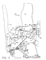
- a flow path represented by an arrow 72 for fan 12 is defined by a fan casing 74 and a hub 76 for first fan stage 16 (see Fig. 2). It will be seen that flow path 72 is then preferably divided upstream of second fan stage 20, where an outer portion represented by an arrow 78 bypasses the rest of engine 10 (except for passing through second fan stage 20) and an inner portion represented by arrow 80 is directed into booster compressor 36 and an inlet duct 82 to high pressure compressor 28. It will be appreciated that a splitter nose 84 is provided in order to divide flow path 72, which will be discussed in greater detail herein. In association with splitter nose 84, an inner bypass platform member 86 and a wall 88 positioned downstream thereof are provided so as to maintain a bypass duct 90 with fan casing 74 through which outer flow path portion 78 flows.
- second fan stage 18 preferably includes a conventional disk 98 having dovetails therein to retain fan blades 22.
- Disk 98 is connected to a fan shaft extension identified generally by reference numeral 100, which is in turn connected to forward conical outer shaft extension 70. In this way, disk 98 and fan blades 22 are then driven by low pressure outer drive shaft 48.
- fan shaft extension 100 preferably includes a first or inner annular portion 102 having a first end 104 connected to forward conical outer shaft extension 70.
- Fan shaft extension 100 also preferably includes a second or outer annular portion 106 having a second end 108 connected to a flange 110 extending from an aft end of disk 98 by means of a bolt 112 and swage nut 114.
- a first platform member 116 is preferably integral with inner annular portion 102 at a second end 118 of fan shaft extension 100, where first platform member 116 serves as a portion of an inner flowpath of booster compressor 36.
- a second platform member 120 is preferably integral with outer annular portion 106 of fan shaft extension 100 at a first end 122, where second platform member 120 serves as a portion of an outer flowpath of booster compressor 36.
- a plurality of compressors blade 124 are then preferably positioned between first and second platform members 116 and 120, respectively, so that together a they form second booster compressor blade row 40.
- Splitter nose 84 is preferably connected to a flange 126 extending upstream from disk 98 by means of a bolt 128 and swage nut 130. It will be appreciated that an additional row 132 or spool of booster compressor blades 134 are preferably provided upstream of first booster compressor row 38. In particular, compressor blades 134 preferably extend radially from a portion 136 of splitter nose 84 located upstream of disk 98 into booster flowpath 80. Since compressor blades 134 are indirectly connected to disk 98, and therefore second drive shaft 48, compressor blades 134 will rotate in the same direction as compressor blades 124 and second stage fan blades 22.
- an outer flowpath for booster compressor 36 is formed by splitter nose portion 136, a flowpath filler member 138 (which preferably is also connected to flange 126 by bolt 128 and swage nut 130), and second platform member 120.
- an inner flowpath for booster compressor 36 is formed by a wall 140 connected to hub 76, a platform member 142 associated with compressor blades 134, a platform member 144 associated with first compressor blade row 38, and first platform member 116.
Applications Claiming Priority (2)
| Application Number | Priority Date | Filing Date | Title |
|---|---|---|---|
| US154584 | 2002-05-24 | ||
| US10/154,584 US6666017B2 (en) | 2002-05-24 | 2002-05-24 | Counterrotatable booster compressor assembly for a gas turbine engine |
Publications (3)
| Publication Number | Publication Date |
|---|---|
| EP1365154A2 EP1365154A2 (en) | 2003-11-26 |
| EP1365154A3 EP1365154A3 (en) | 2004-07-07 |
| EP1365154B1 true EP1365154B1 (en) | 2007-05-02 |
Family
ID=29400560
Family Applications (1)
| Application Number | Title | Priority Date | Filing Date |
|---|---|---|---|
| EP03253260A Expired - Fee Related EP1365154B1 (en) | 2002-05-24 | 2003-05-23 | Counterrotatable booster compressor assembly for a gas turbine engine |
Country Status (5)
| Country | Link |
|---|---|
| US (1) | US6666017B2 (ja) |
| EP (1) | EP1365154B1 (ja) |
| JP (1) | JP4975945B2 (ja) |
| CN (1) | CN100338350C (ja) |
| DE (1) | DE60313528T2 (ja) |
Families Citing this family (49)
| Publication number | Priority date | Publication date | Assignee | Title |
|---|---|---|---|---|
| US6763653B2 (en) * | 2002-09-24 | 2004-07-20 | General Electric Company | Counter rotating fan aircraft gas turbine engine with aft booster |
| US6763652B2 (en) * | 2002-09-24 | 2004-07-20 | General Electric Company | Variable torque split aircraft gas turbine engine counter rotating low pressure turbines |
| FR2866073B1 (fr) * | 2004-02-11 | 2006-07-28 | Snecma Moteurs | Turboreacteur ayant deux soufflantes contrarotatives solidaires d'un compresseur a basse pression contrarotatif |
| US7185484B2 (en) * | 2004-08-11 | 2007-03-06 | General Electric Company | Methods and apparatus for assembling a gas turbine engine |
| FR2889863B1 (fr) * | 2005-08-22 | 2007-11-02 | Snecma | Compresseur comportant une pluralite de caissons reconstituant un volume annulaire de separation de flux dans une turbomachine. |
| US7841165B2 (en) * | 2006-10-31 | 2010-11-30 | General Electric Company | Gas turbine engine assembly and methods of assembling same |
| US7926259B2 (en) * | 2006-10-31 | 2011-04-19 | General Electric Company | Turbofan engine assembly and method of assembling same |
| FR2918120B1 (fr) * | 2007-06-28 | 2009-10-02 | Snecma Sa | Turbomachine a double soufflante |
| US8402742B2 (en) | 2007-12-05 | 2013-03-26 | United Technologies Corporation | Gas turbine engine systems involving tip fans |
| US8590286B2 (en) * | 2007-12-05 | 2013-11-26 | United Technologies Corp. | Gas turbine engine systems involving tip fans |
| US8015798B2 (en) * | 2007-12-13 | 2011-09-13 | United Technologies Corporation | Geared counter-rotating gas turbofan engine |
| US20100284785A1 (en) * | 2007-12-28 | 2010-11-11 | Aspi Rustom Wadia | Fan Stall Detection System |
| US8282336B2 (en) * | 2007-12-28 | 2012-10-09 | General Electric Company | Instability mitigation system |
| US20100290906A1 (en) * | 2007-12-28 | 2010-11-18 | Moeckel Curtis W | Plasma sensor stall control system and turbomachinery diagnostics |
| US20100205928A1 (en) * | 2007-12-28 | 2010-08-19 | Moeckel Curtis W | Rotor stall sensor system |
| US20090169356A1 (en) * | 2007-12-28 | 2009-07-02 | Aspi Rustom Wadia | Plasma Enhanced Compression System |
| US8317457B2 (en) * | 2007-12-28 | 2012-11-27 | General Electric Company | Method of operating a compressor |
| US20090169363A1 (en) * | 2007-12-28 | 2009-07-02 | Aspi Rustom Wadia | Plasma Enhanced Stator |
| US8348592B2 (en) * | 2007-12-28 | 2013-01-08 | General Electric Company | Instability mitigation system using rotor plasma actuators |
| US8282337B2 (en) * | 2007-12-28 | 2012-10-09 | General Electric Company | Instability mitigation system using stator plasma actuators |
| US20100047055A1 (en) * | 2007-12-28 | 2010-02-25 | Aspi Rustom Wadia | Plasma Enhanced Rotor |
| FR2935427B1 (fr) * | 2008-08-27 | 2010-09-24 | Snecma | Methode de reduction des niveaux vibratoires d'un doublet et roues aubagees contrarotatives de turbomachine. |
| US8166748B2 (en) * | 2008-11-21 | 2012-05-01 | General Electric Company | Gas turbine engine booster having rotatable radially inwardly extending blades and non-rotatable vanes |
| US8011877B2 (en) * | 2008-11-24 | 2011-09-06 | General Electric Company | Fiber composite reinforced aircraft gas turbine engine drums with radially inwardly extending blades |
| US20100170224A1 (en) * | 2009-01-08 | 2010-07-08 | General Electric Company | Plasma enhanced booster and method of operation |
| US20100172747A1 (en) * | 2009-01-08 | 2010-07-08 | General Electric Company | Plasma enhanced compressor duct |
| DE102009007013A1 (de) * | 2009-01-31 | 2010-08-12 | Deutsches Zentrum für Luft- und Raumfahrt e.V. | Triebwerk, insbesondere CROR-Antrieb, für ein Flugzeug |
| US20140130479A1 (en) * | 2012-11-14 | 2014-05-15 | United Technologies Corporation | Gas Turbine Engine With Mount for Low Pressure Turbine Section |
| RU2553889C1 (ru) * | 2014-02-20 | 2015-06-20 | Открытое акционерное общество "Авиадвигатель" | Газотурбинный двигатель |
| JP7034577B2 (ja) * | 2015-03-06 | 2022-03-14 | 日東電工株式会社 | 水素排出膜 |
| CN105673251A (zh) * | 2016-01-13 | 2016-06-15 | 中国航空动力机械研究所 | 风扇增压级以及涡扇发动机 |
| US10655537B2 (en) | 2017-01-23 | 2020-05-19 | General Electric Company | Interdigitated counter rotating turbine system and method of operation |
| US10544734B2 (en) | 2017-01-23 | 2020-01-28 | General Electric Company | Three spool gas turbine engine with interdigitated turbine section |
| US10539020B2 (en) | 2017-01-23 | 2020-01-21 | General Electric Company | Two spool gas turbine engine with interdigitated turbine section |
| US10544793B2 (en) | 2017-01-25 | 2020-01-28 | General Electric Company | Thermal isolation structure for rotating turbine frame |
| US10876407B2 (en) | 2017-02-16 | 2020-12-29 | General Electric Company | Thermal structure for outer diameter mounted turbine blades |
| US10294821B2 (en) | 2017-04-12 | 2019-05-21 | General Electric Company | Interturbine frame for gas turbine engine |
| US10669893B2 (en) | 2017-05-25 | 2020-06-02 | General Electric Company | Air bearing and thermal management nozzle arrangement for interdigitated turbine engine |
| US10605168B2 (en) | 2017-05-25 | 2020-03-31 | General Electric Company | Interdigitated turbine engine air bearing cooling structure and method of thermal management |
| US10787931B2 (en) | 2017-05-25 | 2020-09-29 | General Electric Company | Method and structure of interdigitated turbine engine thermal management |
| US10718265B2 (en) | 2017-05-25 | 2020-07-21 | General Electric Company | Interdigitated turbine engine air bearing and method of operation |
| US20190120255A1 (en) * | 2017-10-25 | 2019-04-25 | United Technologies Corporation | Segmented structural links for coupled disk frequency tuning |
| JP6953322B2 (ja) * | 2018-02-01 | 2021-10-27 | 本田技研工業株式会社 | ファンブレードの形状決定方法 |
| US11156097B2 (en) | 2019-02-20 | 2021-10-26 | General Electric Company | Turbomachine having an airflow management assembly |
| US11073088B2 (en) | 2019-02-20 | 2021-07-27 | General Electric Company | Gearbox mounting in a turbomachine |
| US11021970B2 (en) | 2019-02-20 | 2021-06-01 | General Electric Company | Turbomachine with alternatingly spaced rotor blades |
| US11753939B2 (en) | 2019-02-20 | 2023-09-12 | General Electric Company | Turbomachine with alternatingly spaced rotor blades |
| US11085515B2 (en) | 2019-02-20 | 2021-08-10 | General Electric Company | Gearbox coupling in a turbomachine |
| US11428160B2 (en) | 2020-12-31 | 2022-08-30 | General Electric Company | Gas turbine engine with interdigitated turbine and gear assembly |
Family Cites Families (18)
| Publication number | Priority date | Publication date | Assignee | Title |
|---|---|---|---|---|
| FR1514932A (fr) * | 1965-06-24 | 1968-03-01 | Snecma | Compresseur axial à double rotor contrarotatif |
| FR1455278A (fr) * | 1965-08-05 | 1966-04-01 | Snecma | Turboréacteur à double flux |
| US3903690A (en) * | 1973-02-12 | 1975-09-09 | Gen Electric | Turbofan engine lubrication means |
| NL8303401A (nl) * | 1982-11-01 | 1984-06-01 | Gen Electric | Aandrijfturbine voor tegengesteld draaiende propellers. |
| GB2194292A (en) * | 1986-08-29 | 1988-03-02 | Gen Electric | High bypass ratio counterrotating turbofan engine |
| US4790133A (en) | 1986-08-29 | 1988-12-13 | General Electric Company | High bypass ratio counterrotating turbofan engine |
| GB2194593B (en) * | 1986-08-29 | 1991-05-15 | Gen Electric | High bypass ratio, counter rotating gearless front fan engine |
| US4860537A (en) | 1986-08-29 | 1989-08-29 | Brandt, Inc. | High bypass ratio counterrotating gearless front fan engine |
| GB2195712B (en) | 1986-10-08 | 1990-08-29 | Rolls Royce Plc | A turbofan gas turbine engine |
| US4976102A (en) * | 1988-05-09 | 1990-12-11 | General Electric Company | Unducted, counterrotating gearless front fan engine |
| FR2646473B1 (fr) * | 1989-04-26 | 1991-07-05 | Snecma | Moteur a soufflantes contrarotatives tractrices |
| US5345760A (en) | 1993-02-05 | 1994-09-13 | General Electric Company | Turboprop booster |
| US5307622A (en) | 1993-08-02 | 1994-05-03 | General Electric Company | Counterrotating turbine support assembly |
| US5388964A (en) * | 1993-09-14 | 1995-02-14 | General Electric Company | Hybrid rotor blade |
| DE19828562B4 (de) * | 1998-06-26 | 2005-09-08 | Mtu Aero Engines Gmbh | Triebwerk mit gegenläufig drehenden Rotoren |
| US6158210A (en) | 1998-12-03 | 2000-12-12 | General Electric Company | Gear driven booster |
| US6220012B1 (en) * | 1999-05-10 | 2001-04-24 | General Electric Company | Booster recirculation passageway and methods for recirculating air |
| USH2032H1 (en) | 1999-10-01 | 2002-07-02 | The United States Of America As Represented By The Secretary Of The Air Force | Integrated fan-core twin spool counter-rotating turbofan gas turbine engine |
-
2002
- 2002-05-24 US US10/154,584 patent/US6666017B2/en not_active Expired - Lifetime
-
2003
- 2003-05-23 JP JP2003145570A patent/JP4975945B2/ja not_active Expired - Fee Related
- 2003-05-23 DE DE60313528T patent/DE60313528T2/de not_active Expired - Lifetime
- 2003-05-23 EP EP03253260A patent/EP1365154B1/en not_active Expired - Fee Related
- 2003-05-26 CN CNB031409423A patent/CN100338350C/zh not_active Expired - Fee Related
Also Published As
| Publication number | Publication date |
|---|---|
| US6666017B2 (en) | 2003-12-23 |
| JP4975945B2 (ja) | 2012-07-11 |
| CN100338350C (zh) | 2007-09-19 |
| DE60313528T2 (de) | 2008-01-03 |
| EP1365154A2 (en) | 2003-11-26 |
| US20030217546A1 (en) | 2003-11-27 |
| DE60313528D1 (de) | 2007-06-14 |
| EP1365154A3 (en) | 2004-07-07 |
| JP2004003488A (ja) | 2004-01-08 |
| CN1459556A (zh) | 2003-12-03 |
Similar Documents
| Publication | Publication Date | Title |
|---|---|---|
| EP1365154B1 (en) | Counterrotatable booster compressor assembly for a gas turbine engine | |
| EP1367250B1 (en) | Counter-rotatable booster compressor assembly for a gas turbine engine | |
| EP1403485B1 (en) | Gas turbine engine with low pressure turbine comprising counter rotatable low pressure inner and outer shaft turbines | |
| EP1403500B1 (en) | Aircraft gas turbine engine having variable torque split counter rotating low pressure turbines and single direction of rotation booster aft of counter rotating fans | |
| EP1403499B1 (en) | Counter rotating fan aircraft gas turbine engine with aft booster | |
| EP1387060B1 (en) | Aircraft gas turbine engine with control vanes for counter rotating low pressure turbines | |
| EP1626002B1 (en) | Gas turbine engine turbine assembly | |
| US6711887B2 (en) | Aircraft gas turbine engine with tandem non-interdigitated counter rotating low pressure turbines | |
| EP1825111B1 (en) | Counter-rotating compressor case for a tip turbine engine | |
| US20080219833A1 (en) | Inducer for a Fan Blade of a Tip Turbine Engine | |
| EP3159503B1 (en) | Compressor bleeding arrangement for a gas turbine and method of manufacturing a compressor section for a gas turbine | |
| CN212717365U (zh) | 用于飞行器的气体涡轮引擎 |
Legal Events
| Date | Code | Title | Description |
|---|---|---|---|
| PUAI | Public reference made under article 153(3) epc to a published international application that has entered the european phase |
Free format text: ORIGINAL CODE: 0009012 |
|
| AK | Designated contracting states |
Kind code of ref document: A2 Designated state(s): AT BE BG CH CY CZ DE DK EE ES FI FR GB GR HU IE IT LI LU MC NL PT RO SE SI SK TR |
|
| AX | Request for extension of the european patent |
Extension state: AL LT LV MK |
|
| PUAL | Search report despatched |
Free format text: ORIGINAL CODE: 0009013 |
|
| AK | Designated contracting states |
Kind code of ref document: A3 Designated state(s): AT BE BG CH CY CZ DE DK EE ES FI FR GB GR HU IE IT LI LU MC NL PT RO SE SI SK TR |
|
| AX | Request for extension of the european patent |
Extension state: AL LT LV MK |
|
| RIC1 | Information provided on ipc code assigned before grant |
Ipc: 7F 02C 3/073 B Ipc: 7F 02C 3/067 B Ipc: 7F 04D 25/04 B Ipc: 7F 04D 19/02 A |
|
| 17P | Request for examination filed |
Effective date: 20050107 |
|
| AKX | Designation fees paid |
Designated state(s): DE FR GB |
|
| GRAP | Despatch of communication of intention to grant a patent |
Free format text: ORIGINAL CODE: EPIDOSNIGR1 |
|
| GRAS | Grant fee paid |
Free format text: ORIGINAL CODE: EPIDOSNIGR3 |
|
| GRAA | (expected) grant |
Free format text: ORIGINAL CODE: 0009210 |
|
| AK | Designated contracting states |
Kind code of ref document: B1 Designated state(s): DE FR GB |
|
| REG | Reference to a national code |
Ref country code: GB Ref legal event code: FG4D |
|
| REF | Corresponds to: |
Ref document number: 60313528 Country of ref document: DE Date of ref document: 20070614 Kind code of ref document: P |
|
| ET | Fr: translation filed | ||
| PLBE | No opposition filed within time limit |
Free format text: ORIGINAL CODE: 0009261 |
|
| STAA | Information on the status of an ep patent application or granted ep patent |
Free format text: STATUS: NO OPPOSITION FILED WITHIN TIME LIMIT |
|
| 26N | No opposition filed |
Effective date: 20080205 |
|
| REG | Reference to a national code |
Ref country code: FR Ref legal event code: PLFP Year of fee payment: 13 |
|
| PGFP | Annual fee paid to national office [announced via postgrant information from national office to epo] |
Ref country code: DE Payment date: 20150528 Year of fee payment: 13 Ref country code: GB Payment date: 20150527 Year of fee payment: 13 |
|
| PGFP | Annual fee paid to national office [announced via postgrant information from national office to epo] |
Ref country code: FR Payment date: 20150519 Year of fee payment: 13 |
|
| REG | Reference to a national code |
Ref country code: DE Ref legal event code: R119 Ref document number: 60313528 Country of ref document: DE |
|
| GBPC | Gb: european patent ceased through non-payment of renewal fee |
Effective date: 20160523 |
|
| REG | Reference to a national code |
Ref country code: FR Ref legal event code: ST Effective date: 20170131 |
|
| PG25 | Lapsed in a contracting state [announced via postgrant information from national office to epo] |
Ref country code: FR Free format text: LAPSE BECAUSE OF NON-PAYMENT OF DUE FEES Effective date: 20160531 Ref country code: DE Free format text: LAPSE BECAUSE OF NON-PAYMENT OF DUE FEES Effective date: 20161201 |
|
| PG25 | Lapsed in a contracting state [announced via postgrant information from national office to epo] |
Ref country code: GB Free format text: LAPSE BECAUSE OF NON-PAYMENT OF DUE FEES Effective date: 20160523 |