EP1365150A1 - Variable displacement type swash plate clutch-less compressor - Google Patents
Variable displacement type swash plate clutch-less compressor Download PDFInfo
- Publication number
- EP1365150A1 EP1365150A1 EP01948010A EP01948010A EP1365150A1 EP 1365150 A1 EP1365150 A1 EP 1365150A1 EP 01948010 A EP01948010 A EP 01948010A EP 01948010 A EP01948010 A EP 01948010A EP 1365150 A1 EP1365150 A1 EP 1365150A1
- Authority
- EP
- European Patent Office
- Prior art keywords
- valve
- casing
- valve element
- discharge
- seating surface
- Prior art date
- Legal status (The legal status is an assumption and is not a legal conclusion. Google has not performed a legal analysis and makes no representation as to the accuracy of the status listed.)
- Granted
Links
- 238000006073 displacement reaction Methods 0.000 title 1
- 239000003507 refrigerant Substances 0.000 claims abstract description 66
- 230000006835 compression Effects 0.000 claims abstract description 24
- 238000007906 compression Methods 0.000 claims abstract description 24
- 230000002093 peripheral effect Effects 0.000 claims description 34
- 238000011144 upstream manufacturing Methods 0.000 claims description 8
- 238000010276 construction Methods 0.000 description 14
- 238000001816 cooling Methods 0.000 description 13
- 230000000694 effects Effects 0.000 description 8
- 244000145845 chattering Species 0.000 description 6
- 238000005461 lubrication Methods 0.000 description 4
- 238000004891 communication Methods 0.000 description 3
- 230000007423 decrease Effects 0.000 description 3
- 125000006850 spacer group Chemical group 0.000 description 3
- 230000003247 decreasing effect Effects 0.000 description 2
- 230000001050 lubricating effect Effects 0.000 description 2
- 239000000696 magnetic material Substances 0.000 description 2
- 238000000034 method Methods 0.000 description 2
- 230000010349 pulsation Effects 0.000 description 2
- 238000005452 bending Methods 0.000 description 1
- 230000015572 biosynthetic process Effects 0.000 description 1
- 230000000903 blocking effect Effects 0.000 description 1
- 238000007710 freezing Methods 0.000 description 1
- 230000008014 freezing Effects 0.000 description 1
- 238000004519 manufacturing process Methods 0.000 description 1
- 239000000463 material Substances 0.000 description 1
- 239000011347 resin Substances 0.000 description 1
- 229920005989 resin Polymers 0.000 description 1
Images







Classifications
-
- F—MECHANICAL ENGINEERING; LIGHTING; HEATING; WEAPONS; BLASTING
- F04—POSITIVE - DISPLACEMENT MACHINES FOR LIQUIDS; PUMPS FOR LIQUIDS OR ELASTIC FLUIDS
- F04B—POSITIVE-DISPLACEMENT MACHINES FOR LIQUIDS; PUMPS
- F04B49/00—Control, e.g. of pump delivery, or pump pressure of, or safety measures for, machines, pumps, or pumping installations, not otherwise provided for, or of interest apart from, groups F04B1/00 - F04B47/00
- F04B49/22—Control, e.g. of pump delivery, or pump pressure of, or safety measures for, machines, pumps, or pumping installations, not otherwise provided for, or of interest apart from, groups F04B1/00 - F04B47/00 by means of valves
-
- F—MECHANICAL ENGINEERING; LIGHTING; HEATING; WEAPONS; BLASTING
- F04—POSITIVE - DISPLACEMENT MACHINES FOR LIQUIDS; PUMPS FOR LIQUIDS OR ELASTIC FLUIDS
- F04B—POSITIVE-DISPLACEMENT MACHINES FOR LIQUIDS; PUMPS
- F04B27/00—Multi-cylinder pumps specially adapted for elastic fluids and characterised by number or arrangement of cylinders
- F04B27/08—Multi-cylinder pumps specially adapted for elastic fluids and characterised by number or arrangement of cylinders having cylinders coaxial with, or parallel or inclined to, main shaft axis
- F04B27/14—Control
- F04B27/16—Control of pumps with stationary cylinders
- F04B27/18—Control of pumps with stationary cylinders by varying the relative positions of a swash plate and a cylinder block
- F04B27/1804—Controlled by crankcase pressure
-
- F—MECHANICAL ENGINEERING; LIGHTING; HEATING; WEAPONS; BLASTING
- F04—POSITIVE - DISPLACEMENT MACHINES FOR LIQUIDS; PUMPS FOR LIQUIDS OR ELASTIC FLUIDS
- F04B—POSITIVE-DISPLACEMENT MACHINES FOR LIQUIDS; PUMPS
- F04B49/00—Control, e.g. of pump delivery, or pump pressure of, or safety measures for, machines, pumps, or pumping installations, not otherwise provided for, or of interest apart from, groups F04B1/00 - F04B47/00
- F04B49/22—Control, e.g. of pump delivery, or pump pressure of, or safety measures for, machines, pumps, or pumping installations, not otherwise provided for, or of interest apart from, groups F04B1/00 - F04B47/00 by means of valves
- F04B49/24—Bypassing
- F04B49/246—Bypassing by keeping open the outlet valve
-
- F—MECHANICAL ENGINEERING; LIGHTING; HEATING; WEAPONS; BLASTING
- F16—ENGINEERING ELEMENTS AND UNITS; GENERAL MEASURES FOR PRODUCING AND MAINTAINING EFFECTIVE FUNCTIONING OF MACHINES OR INSTALLATIONS; THERMAL INSULATION IN GENERAL
- F16K—VALVES; TAPS; COCKS; ACTUATING-FLOATS; DEVICES FOR VENTING OR AERATING
- F16K15/00—Check valves
- F16K15/02—Check valves with guided rigid valve members
- F16K15/025—Check valves with guided rigid valve members the valve being loaded by a spring
- F16K15/026—Check valves with guided rigid valve members the valve being loaded by a spring the valve member being a movable body around which the medium flows when the valve is open
-
- F—MECHANICAL ENGINEERING; LIGHTING; HEATING; WEAPONS; BLASTING
- F16—ENGINEERING ELEMENTS AND UNITS; GENERAL MEASURES FOR PRODUCING AND MAINTAINING EFFECTIVE FUNCTIONING OF MACHINES OR INSTALLATIONS; THERMAL INSULATION IN GENERAL
- F16K—VALVES; TAPS; COCKS; ACTUATING-FLOATS; DEVICES FOR VENTING OR AERATING
- F16K17/00—Safety valves; Equalising valves, e.g. pressure relief valves
- F16K17/02—Safety valves; Equalising valves, e.g. pressure relief valves opening on surplus pressure on one side; closing on insufficient pressure on one side
- F16K17/04—Safety valves; Equalising valves, e.g. pressure relief valves opening on surplus pressure on one side; closing on insufficient pressure on one side spring-loaded
- F16K17/06—Safety valves; Equalising valves, e.g. pressure relief valves opening on surplus pressure on one side; closing on insufficient pressure on one side spring-loaded with special arrangements for adjusting the opening pressure
-
- F—MECHANICAL ENGINEERING; LIGHTING; HEATING; WEAPONS; BLASTING
- F16—ENGINEERING ELEMENTS AND UNITS; GENERAL MEASURES FOR PRODUCING AND MAINTAINING EFFECTIVE FUNCTIONING OF MACHINES OR INSTALLATIONS; THERMAL INSULATION IN GENERAL
- F16K—VALVES; TAPS; COCKS; ACTUATING-FLOATS; DEVICES FOR VENTING OR AERATING
- F16K47/00—Means in valves for absorbing fluid energy
- F16K47/02—Means in valves for absorbing fluid energy for preventing water-hammer or noise
-
- F—MECHANICAL ENGINEERING; LIGHTING; HEATING; WEAPONS; BLASTING
- F04—POSITIVE - DISPLACEMENT MACHINES FOR LIQUIDS; PUMPS FOR LIQUIDS OR ELASTIC FLUIDS
- F04B—POSITIVE-DISPLACEMENT MACHINES FOR LIQUIDS; PUMPS
- F04B27/00—Multi-cylinder pumps specially adapted for elastic fluids and characterised by number or arrangement of cylinders
- F04B27/08—Multi-cylinder pumps specially adapted for elastic fluids and characterised by number or arrangement of cylinders having cylinders coaxial with, or parallel or inclined to, main shaft axis
- F04B27/14—Control
- F04B27/16—Control of pumps with stationary cylinders
- F04B27/18—Control of pumps with stationary cylinders by varying the relative positions of a swash plate and a cylinder block
- F04B27/1804—Controlled by crankcase pressure
- F04B2027/1863—Controlled by crankcase pressure with an auxiliary valve, controlled by
- F04B2027/1872—Discharge pressure
Definitions
- This invention relates to a clutchless variable capacity swash plate compressor, and more particularly to a clutchless variable capacity swash plate compressor to which torque of an engine is constantly transmitted.
- variable capacity swash plate compressors for air conditioners on vehicles
- a clutchless variable capacity swash plate compressor without an electromagnetic clutch makes it possible not only to solve a problem that bad feeling is given when an air conditioner is switched between an ON state and an OFF state, but also to decrease the weight of the compressor and reduce manufacturing costs.
- the discharge check valve comprises a bottomed hollow cylindrical casing, a valve element slidable within the casing along a direction of depth of the casing, a spring for urging the valve element in a direction of a bottom of the casing, and a stopper for limiting motion of the valve element, the casing having a first seating surface formed on the bottom, a hole formed in a center of the first seating surface, an overlapping portion formed in a manner continuous with the bottom, for being fitted on an end of the valve element by a predetermined length in the direction of depth, and a hollow cylindrical portion formed in a manner continuous with the overlapping portion, for guiding the valve element along the direction of depth, the valve element having a second seating surface formed at an end face thereof, for opening and closing the hole, the overlapping portion and the hollow cylindrical portion being formed in a manner continuous with each other via a tapered surface.
- the discharge check valve comprises a casing, a valve element, and a spring, it is possible to set the valve-opening pressure and the valve-closing pressure as desired, by determining the shapes, sizes, and so forth of these members as required.
- valve opening-delaying means is formed by a first seating surface formed in the casing, a hole formed in the first seating surface, and a second seating surface formed on the valve element, it is possible to set the valve-opening pressure to a predetermined value by determining the sizes, etc. of these components.
- the spherical surface 9a of the hinge ball 9 is fitted in the central through hole of the boss 10c in a manner slidable on the hinge ball-receiving surface 10d.
- a control valve 81 is disposed in an intermediate portion of an air supply passage 57 communicating between the discharge chamber 12 and the crankcase 8.
- the control valve 81 is comprised of a valve portion 81a, a solenoid 81b, and a bellows 81c.
- the bellows 81c expands when suction pressure is lowered, to thereby move the valve portion 81a in the direction of opening the air supply passage 57.
- the solenoid 81b urges the valve portion 81c in the direction of closing the air supply passage 57 when an electric current supplied from a control logic on the vehicle side is increased.
- the suction chamber 13 and the crankcase 8 are in communication with each other via a central hole 1a and a passage 58 formed in the cylinder block 1, and an orifice 2a formed through the valve plate 2.
- the refrigerant outlet ports 16 are opened and closed by respective discharge valves 17, and the discharge valves 17 are fixed to a rear end face of the valve plate 2 by a bolt 19.
- the thrust flange 40 and the swash plate 10 are connected with each other via a linkage 41, whereby the swash plate 10 can tilt with respect to an imaginary plane perpendicular to the shaft 5.
- the valve-receiving hole 11b thus forming part of the discharge passage D has a discharge check valve 130 received therein.
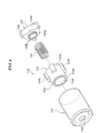
- the discharge check valve 130 is comprised of a casing 131, a valve element 132, a spring 133, and a stopper 134, as shown in FIG. 4.
- the lift portion 131c is formed in a manner continuous with the overlapping portion 131b, and has a tapered surface 131g that cooperates with the end of the valve element 132 to restrict the flow of refrigerant gas.
- the tapered surface 131g expands as the distance from the first seating surface 131e increases.
- the hollow cylindrical portion 131d is formed in a manner continuous with the lift portion 131c, for guiding the valve element 132 along the direction of depth of the casing 131.
- the valve element 132 is received in the casing 131 in a manner slidable within the casing 131 in the direction of depth of the casing 131.
- the valve element 132 is comprised of a body 132a and a plurality of block portions 132b.
- the body 132a has an end formed with a protrusion 132c and a stepped surface 132d surrounding the protrusion 132c.
- the protrusion 132c has an end surface, which forms a second seating surface 132e.
- the second seating surface 132e comes into contact with and moves away from the first seating surface 131e to thereby open and close the through hole 131f.
- the block portions 132b are arranged on the outer peripheral surface of the body 132a at predetermined circumferential intervals.
- the spring 133 is disposed within the casing 131, for urging the valve element 132 toward the bottom portion 131a of the casing 131.
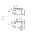
- FIG. 5(a) shows a closed state of the discharge check valve 130.
- the discharge chamber-side discharge pressure (Pdc) acts on a portion of the valve element 132 blocking the through hole 131f of the second seating surface 132e.
- the system-side discharge pressure (Pds) flows into this space 135 through a clearance between the valve element 132 and the overlapping portion 131b, so that the pressure within the space 135 becomes equal to the system-side discharge pressure (Pds).
- FIG. 5(c) shows a fully open state of the discharge check valve 130.
- the overlapping portion 131b is opened, whereby refrigerant gas is delivered to the system side.
- the lift portion 131c has the conical tapered surface 131g, the refrigerant gas flows swiftly without being disturbed.
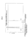
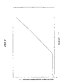
- the lift of the valve element 132 is determined at a balance point determined according to differential pressure across the valve element 132 and the bending amount of the spring 133.
- the discharge check valve 130 is provided in the discharge passage D, even when the air conditioner is in the OFF state and the engine rotates at high speed, the amount of refrigerant gas internally circulated within the compressor is significant, which prevents insufficient lubrication and cooling of the sliding portions.
- FIG. 8 is an exploded perspective view of a discharge check valve provided in a clutchless variable capacity swash plate compressor according to a second embodiment of the present invention
- FIG. 9 illustrates a valve element of the FIG. 8 discharge check valve, in which FIG. 9(a) is a plan view thereof, and FIG. 9(b) is a cross-sectional view taken on line II-II.
- a valve element 132-3 of the discharge check valve 130-3 has an end formed with a projection 132h having a generally conical shape.
- the projection 132h serves to make smooth the flow in the neighborhood of the through hole 131f and reduce flow passage resistance when the valve is open.
- the operation of the discharge check valve 130-3 is identical to that of the FIG. 4 discharge check valve.
- FIG. 11 illustrates a discharge check valve provided in a clutchless variable capacity swash plate compressor according to a fourth embodiment of the present invention, in which FIG. 11(a) is a plan view of a valve element; FIG. 11(b) is a cross-sectional view taken on line III-III; FIG. 11(c) is a plan view of a stopper; FIG. 11(d) is a cross-sectional view taken on line IV-IV; FIG. 11(e) is a cross-sectional view of a casing; and FIG. 11(f) is a cross-sectional view of the discharge check valve.
- FIG. 11(a) is a plan view of a valve element
- FIG. 11(b) is a cross-sectional view taken on line III-III
- FIG. 11(c) is a plan view of a stopper
- FIG. 11(d) is a cross-sectional view taken on line IV-IV
- FIG. 11(e) is a cross-sectional view of a casing
- the casing 131 is press-fitted into the valve-receiving hole 11b, whereas in the discharge check valve 130-4, only the press-fitted portion 134f is press-fitted into the valve-receiving hole 11b.
- the operation of the discharge check valve 130-4 is identical to that of the FIG. 4 discharge check valve.
- a valve element 132-5 is formed of a magnetic material.
- the valve element 132-5 has an end face, which forms a second seating surface 132h, and the through hole 136b is opened and closed by the second seating surface 132h.
- the attractive force of a magnet for attracting an object is inversely proportional to the square of the distance between the magnet and the object, and hence once the valve element 132-5 has been attracted to the first seating surface 136a of the permanent magnet 136, the magnetic force of the permanent magnet 136 makes the valve element 132-5 difficult to be moved away from the first seating surface 136a, which makes the through hole 136b difficult to open.
- the magnetic force hardly acts on the valve element 132-5, which makes the through hole 136b difficult to close.
- the through hole 136b can be made large, thereby reducing discharge resistance.
- the end of the valve element 132-5 may be formed by a magnet, and the bottom portion 131a of the casing 131-5 may be formed of a magnetic material or by an attraction member, such as a magnet opposite in polarity.
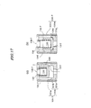
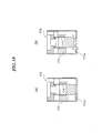
- the discharge check valve 130-6 is generally similar in construction to the discharge check valve shown in FIG. 4. Therefore, component parts and elements corresponding to those of the FIG. 4 discharge check valve are designated by identical reference numerals, and description thereof is omitted. In the following, a description will be given of only differences in construction from the FIG. 4 discharge check valve.
- the discharge check valve 130-7 is generally similar in construction to the discharge check valve shown in FIG. 4. Therefore, component parts and elements corresponding to those of the FIG. 4 discharge check valve are designated by identical reference numerals, and description thereof is omitted. In the following, a description will be given of only differences in construction from the FIG. 4 discharge check valve.
- the discharge check valve 130-7 has a casing 131-7 formed therein with gas passages 131i.
- the casing 131-7 is different in construction from the casing 131-6 in the sixth embodiment.
- the valve seat portion 131m has a bottom portion 131a and an overlapping portion 131b.
- a valve element 132-7 is identical in construction to the valve element 132-6 in the sixth embodiment.
- the gas passages may be formed in the valve element 132. If the gas passages are formed in the valve element 132, the weight of the valve element 132 is reduced by the formation of the gas passages, which reduces an inertial force acting on the valve element 132, and hence suppresses occurrence of chattering.
Landscapes
- Engineering & Computer Science (AREA)
- General Engineering & Computer Science (AREA)
- Mechanical Engineering (AREA)
- Compressors, Vaccum Pumps And Other Relevant Systems (AREA)
- Compressor (AREA)
Abstract
Description
Claims (19)
- A clutchless variable capacity swash plate compressor comprising:a shaft rotatably supported within a housing;a swash plate tiltably mounted on said shaft, for rotation in unison therewith;a discharge passage via which refrigerant gas delivered from a compression chamber to a discharge chamber is sent out of the compressor; anda discharge check valve provided in said discharge passage and having a valve-closing pressure lower than a valve-opening pressure.
- A clutchless variable capacity swash plate compressor comprising:wherein said discharge check valve comprises:a shaft rotatably supported within a housing;a swash plate tiltably mounted on said shaft, for rotation in unison therewith;a discharge passage via which refrigerant gas delivered from a compression chamber to a discharge chamber is sent out of the compressor; anda discharge check valve provided in said discharge passage and having a valve-closing pressure lower than a valve-opening pressure,a bottomed hollow cylindrical casing,a valve element slidable within said casing along a direction of depth of said casing,a spring for urging said valve element in a direction. of a bottom of said casing, anda stopper for limiting motion of said valve element,said casing having a first seating surface formed on said bottom, a hole formed in a center of said first seating surface, an overlapping portion formed in a manner continuous with said bottom, for being fitted on an end of said valve element by a predetermined length in the direction of depth, and a hollow cylindrical portion formed in a manner continuous with said overlapping portion, for guiding said valve element along the direction of depth,said valve element having a second seating surface formed at an end face thereof, for opening and closing said hole.
- A clutchless variable capacity swash plate compressor comprising:wherein said discharge check valve comprises:a shaft rotatably supported within a housing;a swash plate tiltably mounted on said shaft, for rotation in unison therewith;a discharge passage via which refrigerant gas delivered from a compression chamber to a discharge chamber is sent out of the compressor; anda discharge check valve provided in said discharge passage and having a valve-closing pressure lower than a valve-opening pressure,a bottomed hollow cylindrical casing,a valve element slidable within said casing along a direction of depth of said casing,a spring for urging said valve element in a direction of a bottom of said casing, anda stopper for limiting motion of said valve element,said casing having a first seating surface formed on said bottom, a hole formed in a center of said first seating surface, an overlapping portion formed in a manner continuous with said bottom, for being fitted on an end of said valve element by a predetermined length in the direction of depth, and a hollow cylindrical portion formed in a manner continuous with said overlapping portion, for guiding said valve element along the direction of depth,said valve element having a second seating surface formed at an end face thereof, for opening and closing said hole,said overlapping portion and said hollow cylindrical portion being formed in a manner continuous with each other via a tapered surface.
- A clutchless variable capacity swash plate compressor comprising:wherein said discharge check valve comprises:a shaft rotatably supported within a housing;a swash plate tiltably mounted on said shaft, for rotation in unison therewith;a discharge passage via which refrigerant gas delivered from a compression chamber to a discharge chamber is sent out of the compressor; anda discharge check valve provided in said discharge passage and having a valve-closing pressure lower than a valve-opening pressure,a bottomed hollow cylindrical casing,a valve element slidable within said casing along a direction of depth of said casing,a spring for urging said valve element in a direction of a bottom of said casing, anda stopper for limiting motion of said valve element,said casing having a first seating surface formed on said bottom, a hole formed in a center of said first seating surface, an overlapping portion formed in a manner continuous with said bottom, for being fitted on an end of said valve element by a predetermined length in the direction of depth, and a hollow cylindrical portion formed in a manner continuous with said overlapping portion, for guiding said valve element along the direction of depth,said valve element having a second seating surface formed at an end face thereof, for opening and closing said hole,said valve element having a stepped surface that surrounds said second seating surface, and forms a space into which pressure behind said valve element is introduced, between said stepped surface and said first seating surface, when said second seating surface is in contact with said first seating surface.
- A clutchless variable capacity swash plate compressor comprising:wherein said discharge check valve comprises:a shaft rotatably supported within a housing;a swash plate tiltably mounted on said shaft, for rotation in unison therewith;a discharge passage via which refrigerant gas delivered from a compression chamber to a discharge chamber is sent out of the compressor; anda discharge check valve provided in said discharge passage and having a valve-closing pressure lower than a valve-opening pressure,a bottomed hollow cylindrical casing,a valve element slidable within said casing along a direction of depth of said casing,a spring for urging said valve element in a direction of a bottom of said casing, anda stopper for limiting motion of said valve element,said casing having a first seating surface formed on said bottom, a hole formed in a center of said first seating surface, an overlapping portion formed in a manner continuous with said bottom, for being fitted on an end of said valve element by a predetermined length in the direction of depth, and a hollow cylindrical portion formed in a manner continuous with said overlapping portion, for guiding said valve element along the direction of depth,said valve element having a second seating surface formed at an end face thereof, for opening and closing said hole,said overlapping portion and said hollow cylindrical portion being formed in a manner continuous with each other via a tapered surface,said valve element having a stepped surface that surrounds said second seating surface, and forms a space into which pressure behind said valve element is introduced, between said stepped surface and said first seating surface, when said second seating surface is in contact with said first seating surface.
- A clutchless variable capacity swash plate compressor comprising:wherein said discharge check valve comprises:a shaft rotatably supported within a housing;a swash plate tiltably mounted on said shaft, for rotation in unison therewith;a discharge passage via which refrigerant gas delivered from a compression chamber to a discharge chamber is sent out of the compressor; anda discharge check valve provided in said discharge passage and having a valve-closing pressure lower than a valve-opening pressure,a bottomed hollow cylindrical casing,a valve element slidable within said casing along a direction of depth of said casing,a spring for urging said valve element in a direction of a bottom of said casing, anda stopper for limiting motion of said valve element,one of said casing and said valve element having a magnet, and the other of said casing and said valve element having an attraction member for being attracted by said magnet in the direction of depth.
- A clutchless variable capacity swash plate compressor comprising:a shaft rotatably supported within a housing;a swash plate tiltably mounted on said shaft, for rotation in unison therewith;a discharge passage via which refrigerant gas delivered from a compression chamber to a discharge chamber is sent out of the compressor; anda discharge check valve provided in said discharge passage, said discharge check valve having at least one of valve opening-delaying means for delaying valve-opening thereof to thereby make a valve-closing pressure thereof lower than a valve-opening pressure thereof, and valve closing-delaying means for delaying valve-closing thereof to thereby make the valve-closing pressure thereof lower than the valve-opening pressure thereof.
- A clutchless variable capacity swash plate compressor comprising:wherein said discharge check valve comprises:a shaft rotatably supported within a housing;a swash plate tiltably mounted on said shaft, for rotation in unison therewith;a discharge passage via which refrigerant gas delivered from a compression chamber to a discharge chamber is sent out of the compressor; anda discharge check valve provided in said discharge passage, said discharge check valve having at least one of valve opening-delaying means for delaying valve-opening thereof to thereby make a valve-closing pressure thereof lower than a valve-opening pressure thereof, and valve closing-delaying means for delaying valve-closing thereof to thereby make the valve-closing pressure thereof lower than the valve-opening pressure thereof,a casing,a valve element slidable within said casing along a direction of depth of said casing, anda spring for urging said valve element in a direction of one end of said casing.
- A clutchless variable capacity swash plate compressor comprising:wherein said discharge check valve comprises:a shaft rotatably supported within a housing;a swash plate tiltably mounted on said shaft, for rotation in unison therewith;a discharge passage via which refrigerant gas delivered from a compression chamber to a discharge chamber is sent out of the compressor; anda discharge check valve provided in said discharge passage, said discharge check valve having valve opening-delaying means for delaying valve-opening thereof to thereby make a valve-closing pressure thereof lower than a valve-opening pressure thereof,a casing,a valve element slidable within said casing along a direction of depth of said casing, anda spring for urging said valve element in a direction of one end of said casing,said valve opening-delaying means being formed by a first seating surface formed in said one end of said casing, a hole formed in said first seating surface, and a second seating surface formed on said valve element in a manner opposed to said hole,said second seating surface being smaller than said first seating surface and larger than said hole.
- A clutchless variable capacity swash plate compressor comprising:wherein said discharge check valve comprises:a shaft rotatably supported within a housing;a swash plate tiltably mounted on said shaft, for rotation in unison therewith;a discharge passage via which refrigerant gas delivered from a compression chamber to a discharge chamber is sent out of the compressor; anda discharge check valve provided in said discharge passage, said discharge check valve having valve closing-delaying means for delaying valve-closing thereof to thereby make a valve-closing pressure thereof lower than a valve-opening pressure thereof,a casing,a valve element slidable within said casing along a direction of depth of said casing, anda spring for urging said valve element in a direction of one end of said casing,said valve opening-delaying means being formed by a first seating surface formed in said one end of said casing, a hole formed in said first seating surface, and an overlapping portion formed in said casing in a manner enclosing said first seating surface, for having an end of said valve element fitted therein in the direction of depth.
- A clutchless variable capacity swash plate compressor comprising:wherein said discharge check valve comprises:a shaft rotatably supported within a housing;a swash plate tiltably mounted on said shaft, for rotation in unison therewith;a discharge passage via which refrigerant gas delivered from a compression chamber to a discharge chamber is sent out of the compressor; anda discharge check valve provided in said discharge passage, said discharge check valve having valve opening-delaying means for delaying valve-opening thereof to thereby make a valve-closing pressure thereof lower than a valve-opening pressure thereof, and valve closing-delaying means for delaying valve-closing thereof to thereby make the valve-closing pressure thereof lower than the valve-opening pressure thereof,a casing,a valve element slidable within said casing along a direction of depth of said casing, anda spring for urging said valve element in a direction of one end of said casing,said valve opening-delaying means being formed by a first seating surface formed in said one end of said casing, a hole formed in said first seating surface, and a second seating surface formed on said valve element in a manner opposed to said hole,said second seating surface being smaller than said first seating surface and larger than said hole,said valve closing-delaying means being formed by the first seating surface formed in said one end of said casing, the hole formed in said first seating surface, and an overlapping portion formed in said casing in a manner enclosing said first seating surface, for having an end of said valve element fitted therein in the direction of depth.
- A clutchless variable capacity swash plate compressor comprising:wherein said discharge check valve comprises:a shaft rotatably supported within a housing;a swash plate tiltably mounted on said shaft, for rotation in unison therewith;a discharge passage via which refrigerant gas delivered from a compression chamber to a discharge chamber is sent out of the compressor; anda discharge check valve provided in said discharge passage, said discharge check valve having valve closing-delaying means for delaying valve-closing thereof to thereby make a valve-closing pressure thereof lower than a valve-opening pressure thereof,wherein a gas flow passage is formed in an inner peripheral surface of said guide portion, for causing the refrigerant gas flowing into said casing via said hole to flow downstream of said valve element.a casing,a valve element slidable within said casing along a direction of depth of said casing, anda spring for urging said valve element in a direction of one end of said casing,said valve closing-delaying means being formed by a first seating surface formed in said one end of said casing, a hole formed in said first seating surface, and an overlapping portion formed in said casing in a manner enclosing said first seating surface, for having an end of said valve element fitted therein in the direction of depth,said casing having a guide portion formed in a manner continuous with said overlapping portion, for guiding said valve element in the direction of depth,
- A clutchless variable capacity swash plate compressor comprising:wherein said discharge check valve comprises:a shaft rotatably supported within a housing;a swash plate tiltably mounted on said shaft, for rotation in unison therewith;a discharge passage via which refrigerant gas delivered from a compression chamber to a discharge chamber is sent out of the compressor; anda discharge check valve provided in said discharge passage, said discharge check valve having valve opening-delaying means for delaying valve-opening thereof to thereby make a valve-closing pressure thereof lower than a valve-opening pressure thereof, and valve closing-delaying means for delaying valve-closing thereof to thereby make the valve-closing pressure thereof lower than the valve-opening pressure thereof,wherein a gas flow passage is formed in an inner peripheral surface of said guide portion, for causing the refrigerant gas flowing into said casing via said hole to flow downstream of said valve element.a casing,a valve element slidable within said casing along a direction of depth of said casing, anda spring for urging said valve element in a direction of one end of said casing,said valve opening-delaying means being formed by a first seating surface formed in said one end of said casing, a hole formed in said first seating surface, and a second seating surface formed on said valve element in a manner opposed to said hole,said second seating surface being smaller than said first seating surface and larger than said hole,said valve closing-delaying means being formed by a first seating surface formed in said one end of said casing, a hole formed in said first seating surface, and an overlapping portion formed in said casing in a manner enclosing said first seating surface, for having an end of said valve element fitted therein in the direction of depth,said casing having a guide portion formed in a manner continuous with said overlapping portion, for guiding said valve element in the direction of depth,
- A clutchless variable capacity swash plate compressor comprising:wherein said discharge check valve comprises:a shaft rotatably supported within a housing;a swash plate tiltably mounted on said shaft, for rotation in unison therewith;a discharge passage via which refrigerant gas delivered from a compression chamber to a discharge chamber is sent out of the compressor; anda discharge check valve provided in said discharge passage, said discharge check valve having at least one of valve opening-delaying means for delaying valve-opening thereof to thereby make a valve-closing pressure thereof lower than a valve-opening pressure thereof, and valve closing-delaying means for delaying valve-closing thereof to thereby make the valve-closing pressure thereof lower than the valve-opening pressure thereof,wherein a hole is formed in one end of said casing, for being opened and closed by said valve element, anda casing,a valve element slidable within said casing along a direction of depth of said casing, anda spring for urging said valve element in a direction of one end of said casing,
wherein a gas flow passage is formed in an outer peripheral surface of said valve element, for causing the refrigerant gas flowing into said casing via said hole to flow downstream of said valve element. - A clutchless variable capacity swash plate compressor comprising:a shaft rotatably supported within a housing;a swash plate tiltably mounted on said shaft, for rotation in unison therewith;a discharge passage via which refrigerant gas delivered from a compression chamber to a discharge chamber is sent out of the compressor; anda discharge check valve provided in said discharge passage, and having opening/closing control means for opening said discharge passage when a differential pressure between an upstream side and a downstream side thereof exceeds a first predetermined value and closing said discharge passage when the differential pressure between the upstream side and the downstream side thereof becomes lower than a second predetermined value lower than the first predetermined value.
- A clutchless variable capacity swash plate compressor comprising:wherein said opening/closing control means being formed by at least one of valve opening-delaying means for setting the first predetermined value, and valve closing-delaying means for setting the second predetermined value.a shaft rotatably supported within a housing;a swash plate tiltably mounted on said shaft, for rotation in unison therewith;a discharge passage via which refrigerant gas delivered from a compression chamber to a discharge chamber is sent out of the compressor; anda discharge check valve provided in said discharge passage, and having opening/closing control means for opening said discharge passage when a differential pressure between an upstream side and a downstream side thereof exceeds a first predetermined value and closing said discharge passage when the differential pressure between the upstream side and the downstream side thereof becomes lower than a second predetermined value lower than the first predetermined value,
- A clutchless variable capacity swash plate compressor as claimed in any one of claims 2 to 6, and 8 to 14, wherein an outer peripheral edge of the end of said valve element is rounded.
- A clutchless variable capacity swash plate compressor as claimed in any one of claims 1 to 17, wherein a minimum inclination angle of said swash plate is set to a value larger than zero.
- A clutchless variable capacity swash plate compressor as claimed in any one of claims 1 to 18, including:an inclination angle-limiting member mounted on said shaft, for determining a minimum inclination angle of said swash plate, andan inclination angle-adjusting member mounted on an swash plate-side end face of said inclination angle-limiting member, for adjusting the minimum inclination angle of said swash plate.
Applications Claiming Priority (3)
| Application Number | Priority Date | Filing Date | Title |
|---|---|---|---|
| JP2001019443 | 2001-01-29 | ||
| JP2001019443 | 2001-01-29 | ||
| PCT/JP2001/006097 WO2002061280A1 (en) | 2001-01-29 | 2001-07-13 | Variable displacement type swash plate clutch-less compressor |
Publications (3)
| Publication Number | Publication Date |
|---|---|
| EP1365150A1 true EP1365150A1 (en) | 2003-11-26 |
| EP1365150A4 EP1365150A4 (en) | 2006-06-07 |
| EP1365150B1 EP1365150B1 (en) | 2016-08-24 |
Family
ID=18885319
Family Applications (1)
| Application Number | Title | Priority Date | Filing Date |
|---|---|---|---|
| EP01948010.2A Expired - Lifetime EP1365150B1 (en) | 2001-01-29 | 2001-07-13 | Variable displacement type swash plate clutch-less compressor |
Country Status (5)
| Country | Link |
|---|---|
| US (1) | US20040062660A1 (en) |
| EP (1) | EP1365150B1 (en) |
| JP (1) | JP4655260B2 (en) |
| DE (1) | DE20122730U1 (en) |
| WO (1) | WO2002061280A1 (en) |
Cited By (4)
| Publication number | Priority date | Publication date | Assignee | Title |
|---|---|---|---|---|
| EP1983191A4 (en) * | 2006-01-30 | 2012-04-25 | Valeo Thermal Sys Japan Co | Variable displacement-type clutchless compressor |
| WO2013084063A1 (en) * | 2011-12-09 | 2013-06-13 | Illinois Tool Works Inc. | Non-return valve |
| EP2573394A4 (en) * | 2010-05-15 | 2015-07-15 | Toyota Jidoshokki Kk | Variable-capacity compressor |
| WO2024079454A1 (en) | 2022-10-10 | 2024-04-18 | Concrete Floor Products Limited | Extender and modular screed rail system |
Families Citing this family (25)
| Publication number | Priority date | Publication date | Assignee | Title |
|---|---|---|---|---|
| JP4734623B2 (en) * | 2003-09-24 | 2011-07-27 | 株式会社ヴァレオジャパン | Variable capacity clutchless compressor |
| JP2006200552A (en) * | 2005-01-18 | 2006-08-03 | Fuji Koki Corp | Check valve |
| JP4826948B2 (en) * | 2005-10-06 | 2011-11-30 | 株式会社ヴァレオジャパン | Piston type compressor |
| JP4330576B2 (en) * | 2005-10-28 | 2009-09-16 | サンデン株式会社 | Compressor |
| JP2009191754A (en) * | 2008-02-15 | 2009-08-27 | Toyota Industries Corp | Variable displacement gear pump |
| DE102008060146A1 (en) * | 2008-12-03 | 2010-06-17 | Thyssenkrupp Presta Ag | Check valve for a hydraulic power steering |
| GB2478876B (en) * | 2009-03-31 | 2012-03-21 | Scion Sprays Ltd | A fluid injector having a novel inlet valve arrangement |
| US8196506B2 (en) * | 2009-08-17 | 2012-06-12 | Delphi Technologies, Inc. | Variable stroke compressor design |
| US20110116940A1 (en) * | 2009-11-17 | 2011-05-19 | Cameron International Corporation | Viscoelastic compressor pulsation dampener |
| CN102918286B (en) | 2010-03-09 | 2016-04-06 | 大丰工业株式会社 | Slide member |
| JP5429143B2 (en) * | 2010-11-25 | 2014-02-26 | 株式会社豊田自動織機 | Differential pressure control valve and variable capacity compressor |
| JP5697022B2 (en) * | 2010-12-14 | 2015-04-08 | サンデン株式会社 | Variable capacity compressor |
| JP5697975B2 (en) * | 2010-12-28 | 2015-04-08 | 株式会社ヴァレオジャパン | Check valve and variable displacement compressor using the same |
| DE102011082728A1 (en) * | 2011-09-15 | 2013-03-21 | Robert Bosch Gmbh | Check valve, in particular for a high-pressure fuel pump, and pump with check valve |
| DE102011117354A1 (en) * | 2011-10-29 | 2013-05-02 | Volkswagen Aktiengesellschaft | Air conditioning compressor for a motor vehicle |
| US9488289B2 (en) * | 2014-01-14 | 2016-11-08 | Hanon Systems | Variable suction device for an A/C compressor to improve nvh by varying the suction inlet flow area |
| JP6237274B2 (en) | 2014-01-30 | 2017-11-29 | 株式会社豊田自動織機 | Compressor check valve |
| JP6179438B2 (en) | 2014-03-28 | 2017-08-16 | 株式会社豊田自動織機 | Variable capacity swash plate compressor |
| JP6194836B2 (en) | 2014-03-28 | 2017-09-13 | 株式会社豊田自動織機 | Variable capacity swash plate compressor |
| JP6179439B2 (en) * | 2014-03-28 | 2017-08-16 | 株式会社豊田自動織機 | Variable capacity swash plate compressor |
| JP6194837B2 (en) | 2014-03-28 | 2017-09-13 | 株式会社豊田自動織機 | Variable capacity swash plate compressor |
| JP6191527B2 (en) | 2014-03-28 | 2017-09-06 | 株式会社豊田自動織機 | Variable capacity swash plate compressor |
| JP6287483B2 (en) | 2014-03-28 | 2018-03-07 | 株式会社豊田自動織機 | Variable capacity swash plate compressor |
| US10591074B2 (en) * | 2016-07-21 | 2020-03-17 | Hanon Systems | Suction dampening device with internal dampening for vehicle air conditioning compressor |
| US11994077B2 (en) * | 2022-05-20 | 2024-05-28 | Woodward, Inc. | Fuel nozzle metering valve that provides dribble flow and related method |
Family Cites Families (20)
| Publication number | Priority date | Publication date | Assignee | Title |
|---|---|---|---|---|
| US2431769A (en) * | 1943-04-30 | 1947-12-02 | Parker Appliance Co | Quick opening check valve assembly |
| JPS58145652A (en) * | 1982-02-24 | 1983-08-30 | 三菱化学株式会社 | Calcium silicate formed body |
| AT377337B (en) * | 1982-03-05 | 1985-03-11 | Hoerbiger Ventilwerke Ag | SUCTION CONTROL VALVE FOR ROTATIONAL COMPRESSORS |
| US4489697A (en) * | 1983-02-22 | 1984-12-25 | Diesel Kiki Co., Ltd. | Distributor type fuel injection pump having a starting injection timing advance device |
| FR2577182B1 (en) * | 1985-02-08 | 1987-04-30 | Cibie Projecteurs | DEVICE FOR FIXING AND ADJUSTING AN OPTICAL BLOCK OF A MOTOR VEHICLE PROJECTOR |
| US4667697A (en) * | 1985-04-08 | 1987-05-26 | Armco, Inc. | Unitized check valve |
| US5092361A (en) * | 1989-03-23 | 1992-03-03 | Nippon Piston Ring Co., Ltd. | Inline type check valve |
| US5112198A (en) * | 1991-02-08 | 1992-05-12 | General Motors Corporation | Refrigerant compressor having variable restriction pressure pulsation attenuator |
| US5577894A (en) * | 1993-11-05 | 1996-11-26 | Kabushiki Kaisha Toyoda Jidoshokki Seisakusho | Piston type variable displacement compressor |
| JP3254853B2 (en) * | 1993-11-05 | 2002-02-12 | 株式会社豊田自動織機 | Clutchless one-sided piston type variable displacement compressor |
| US5605317A (en) * | 1994-03-21 | 1997-02-25 | Sapphire Engineering, Inc. | Electro-magnetically operated valve |
| US5794657A (en) * | 1997-02-07 | 1998-08-18 | Oberg; Gordon D. | Safety check valve for fuel delivery system |
| JP3582284B2 (en) * | 1997-03-13 | 2004-10-27 | 株式会社豊田自動織機 | Refrigeration circuit and compressor |
| JPH10325393A (en) * | 1997-05-26 | 1998-12-08 | Zexel Corp | Variable displacement swash plate type clutchless compressor |
| JPH11173274A (en) * | 1997-12-04 | 1999-06-29 | Zexel:Kk | Variable displacement type swash plate compressor without clutch |
| EP1088991A1 (en) * | 1998-06-16 | 2001-04-04 | Bosch Automotive Systems Corporation | Variable displacement swash plate type clutchless compressor |
| JP2000314377A (en) * | 1999-05-07 | 2000-11-14 | Bosch Automotive Systems Corp | Variable displacement swash plate clutchless compressor |
| JP2000345967A (en) * | 1999-06-07 | 2000-12-12 | Toyota Autom Loom Works Ltd | Variable displacement compressor |
| JP2000346241A (en) * | 1999-06-07 | 2000-12-15 | Toyota Autom Loom Works Ltd | Check valve |
| JP2001132632A (en) * | 1999-11-10 | 2001-05-18 | Toyota Autom Loom Works Ltd | Control valve of variable displacement compressor |
-
2001
- 2001-07-13 EP EP01948010.2A patent/EP1365150B1/en not_active Expired - Lifetime
- 2001-07-13 DE DE20122730U patent/DE20122730U1/en not_active Expired - Lifetime
- 2001-07-13 US US10/470,422 patent/US20040062660A1/en not_active Abandoned
- 2001-07-13 JP JP2002561195A patent/JP4655260B2/en not_active Expired - Fee Related
- 2001-07-13 WO PCT/JP2001/006097 patent/WO2002061280A1/en not_active Ceased
Cited By (5)
| Publication number | Priority date | Publication date | Assignee | Title |
|---|---|---|---|---|
| EP1983191A4 (en) * | 2006-01-30 | 2012-04-25 | Valeo Thermal Sys Japan Co | Variable displacement-type clutchless compressor |
| EP2573394A4 (en) * | 2010-05-15 | 2015-07-15 | Toyota Jidoshokki Kk | Variable-capacity compressor |
| WO2013084063A1 (en) * | 2011-12-09 | 2013-06-13 | Illinois Tool Works Inc. | Non-return valve |
| US10571035B2 (en) | 2011-12-09 | 2020-02-25 | Illinois Tool Works Inc. | Non-return valve |
| WO2024079454A1 (en) | 2022-10-10 | 2024-04-18 | Concrete Floor Products Limited | Extender and modular screed rail system |
Also Published As
| Publication number | Publication date |
|---|---|
| JPWO2002061280A1 (en) | 2004-12-09 |
| JP4655260B2 (en) | 2011-03-23 |
| DE20122730U1 (en) | 2007-08-02 |
| US20040062660A1 (en) | 2004-04-01 |
| EP1365150B1 (en) | 2016-08-24 |
| EP1365150A4 (en) | 2006-06-07 |
| WO2002061280A1 (en) | 2002-08-08 |
Similar Documents
| Publication | Publication Date | Title |
|---|---|---|
| EP1365150B1 (en) | Variable displacement type swash plate clutch-less compressor | |
| JP3131015B2 (en) | Solenoid control valve | |
| JP4829419B2 (en) | Control valve for variable displacement compressor | |
| JP5697975B2 (en) | Check valve and variable displacement compressor using the same | |
| JPH07127566A (en) | Clutchless one side piston type variable displacement compressor | |
| JP6340661B2 (en) | Control valve for variable capacity compressor | |
| EP1512871A1 (en) | Capacity control valve for variable displacement compressor | |
| JP3152015B2 (en) | Clutchless one-sided piston type variable displacement compressor and displacement control method thereof | |
| JP3254872B2 (en) | Clutchless one-sided piston type variable displacement compressor | |
| JP4734623B2 (en) | Variable capacity clutchless compressor | |
| JP2000009045A (en) | Control valve for variable displacement type compressor, variable displacement type compressor, and variable setting method for set suction pressure | |
| JP2016020682A (en) | Control valve for variable capacity type compressor | |
| JP4055410B2 (en) | Capacity control device for variable capacity compressor | |
| EP1411243B1 (en) | Capacity control valve for variable displacement compressor | |
| JPH10141221A (en) | Variable displacement compressor | |
| JP4082802B2 (en) | Control valve for variable displacement compressor | |
| JP7625357B2 (en) | valve | |
| JPH09256947A (en) | Valve seat structure in compressor | |
| JP3182950B2 (en) | Clutchless structure in one-side piston type variable displacement compressor. | |
| EP1088991A1 (en) | Variable displacement swash plate type clutchless compressor | |
| US20060039799A1 (en) | Control valve for variable displacement compressor | |
| JP2000314377A (en) | Variable displacement swash plate clutchless compressor | |
| WO1999025977A1 (en) | Variable displacement swash plate type clutchless compressor | |
| JP3125513B2 (en) | Swash plate type variable displacement compressor | |
| JP3254820B2 (en) | Clutchless one-sided piston type variable displacement compressor |
Legal Events
| Date | Code | Title | Description |
|---|---|---|---|
| PUAI | Public reference made under article 153(3) epc to a published international application that has entered the european phase |
Free format text: ORIGINAL CODE: 0009012 |
|
| 17P | Request for examination filed |
Effective date: 20030829 |
|
| AK | Designated contracting states |
Kind code of ref document: A1 Designated state(s): DE FR GB |
|
| AX | Request for extension of the european patent |
Extension state: AL LT LV MK RO SI |
|
| RIC1 | Information provided on ipc code assigned before grant |
Ipc: 7F 04B 49/22 B Ipc: 7F 04B 27/18 A |
|
| A4 | Supplementary search report drawn up and despatched |
Effective date: 20060508 |
|
| 17Q | First examination report despatched |
Effective date: 20070208 |
|
| GRAP | Despatch of communication of intention to grant a patent |
Free format text: ORIGINAL CODE: EPIDOSNIGR1 |
|
| INTG | Intention to grant announced |
Effective date: 20160126 |
|
| GRAS | Grant fee paid |
Free format text: ORIGINAL CODE: EPIDOSNIGR3 |
|
| GRAA | (expected) grant |
Free format text: ORIGINAL CODE: 0009210 |
|
| AK | Designated contracting states |
Kind code of ref document: B1 Designated state(s): DE FR GB |
|
| REG | Reference to a national code |
Ref country code: GB Ref legal event code: FG4D |
|
| REG | Reference to a national code |
Ref country code: DE Ref legal event code: R096 Ref document number: 60150068 Country of ref document: DE |
|
| REG | Reference to a national code |
Ref country code: DE Ref legal event code: R081 Ref document number: 60150068 Country of ref document: DE Owner name: VALEO JAPAN CO., LTD., KUMAGAYA-SHI, JP Free format text: FORMER OWNER: ZEXEL VALEO CLIMATE CONTROL CORP., SAITAMA, JP |
|
| RAP2 | Party data changed (patent owner data changed or rights of a patent transferred) |
Owner name: VALEO JAPAN CO., LTD. |
|
| REG | Reference to a national code |
Ref country code: DE Ref legal event code: R097 Ref document number: 60150068 Country of ref document: DE |
|
| PLBE | No opposition filed within time limit |
Free format text: ORIGINAL CODE: 0009261 |
|
| STAA | Information on the status of an ep patent application or granted ep patent |
Free format text: STATUS: NO OPPOSITION FILED WITHIN TIME LIMIT |
|
| REG | Reference to a national code |
Ref country code: FR Ref legal event code: PLFP Year of fee payment: 17 |
|
| 26N | No opposition filed |
Effective date: 20170526 |
|
| GBPC | Gb: european patent ceased through non-payment of renewal fee |
Effective date: 20170713 |
|
| PG25 | Lapsed in a contracting state [announced via postgrant information from national office to epo] |
Ref country code: GB Free format text: LAPSE BECAUSE OF NON-PAYMENT OF DUE FEES Effective date: 20170713 |
|
| REG | Reference to a national code |
Ref country code: FR Ref legal event code: PLFP Year of fee payment: 18 |
|
| PGFP | Annual fee paid to national office [announced via postgrant information from national office to epo] |
Ref country code: DE Payment date: 20180710 Year of fee payment: 18 |
|
| PGFP | Annual fee paid to national office [announced via postgrant information from national office to epo] |
Ref country code: FR Payment date: 20190731 Year of fee payment: 19 |
|
| REG | Reference to a national code |
Ref country code: DE Ref legal event code: R119 Ref document number: 60150068 Country of ref document: DE |
|
| PG25 | Lapsed in a contracting state [announced via postgrant information from national office to epo] |
Ref country code: DE Free format text: LAPSE BECAUSE OF NON-PAYMENT OF DUE FEES Effective date: 20200201 |
|
| PG25 | Lapsed in a contracting state [announced via postgrant information from national office to epo] |
Ref country code: FR Free format text: LAPSE BECAUSE OF NON-PAYMENT OF DUE FEES Effective date: 20200731 |