EP1365139A2 - Abnormality diagnostic method for exhaust gas recirculation control system - Google Patents
Abnormality diagnostic method for exhaust gas recirculation control system Download PDFInfo
- Publication number
- EP1365139A2 EP1365139A2 EP03011624A EP03011624A EP1365139A2 EP 1365139 A2 EP1365139 A2 EP 1365139A2 EP 03011624 A EP03011624 A EP 03011624A EP 03011624 A EP03011624 A EP 03011624A EP 1365139 A2 EP1365139 A2 EP 1365139A2
- Authority
- EP
- European Patent Office
- Prior art keywords
- exhaust gas
- tendency
- amount
- abnormality
- intake air
- Prior art date
- Legal status (The legal status is an assumption and is not a legal conclusion. Google has not performed a legal analysis and makes no representation as to the accuracy of the status listed.)
- Granted
Links
Images


Classifications
-
- F—MECHANICAL ENGINEERING; LIGHTING; HEATING; WEAPONS; BLASTING
- F02—COMBUSTION ENGINES; HOT-GAS OR COMBUSTION-PRODUCT ENGINE PLANTS
- F02D—CONTROLLING COMBUSTION ENGINES
- F02D41/00—Electrical control of supply of combustible mixture or its constituents
- F02D41/0025—Controlling engines characterised by use of non-liquid fuels, pluralities of fuels, or non-fuel substances added to the combustible mixtures
- F02D41/0047—Controlling exhaust gas recirculation [EGR]
- F02D41/005—Controlling exhaust gas recirculation [EGR] according to engine operating conditions
- F02D41/0055—Special engine operating conditions, e.g. for regeneration of exhaust gas treatment apparatus
-
- F—MECHANICAL ENGINEERING; LIGHTING; HEATING; WEAPONS; BLASTING
- F02—COMBUSTION ENGINES; HOT-GAS OR COMBUSTION-PRODUCT ENGINE PLANTS
- F02M—SUPPLYING COMBUSTION ENGINES IN GENERAL WITH COMBUSTIBLE MIXTURES OR CONSTITUENTS THEREOF
- F02M26/00—Engine-pertinent apparatus for adding exhaust gases to combustion-air, main fuel or fuel-air mixture, e.g. by exhaust gas recirculation [EGR] systems
- F02M26/49—Detecting, diagnosing or indicating an abnormal function of the EGR system
-
- F—MECHANICAL ENGINEERING; LIGHTING; HEATING; WEAPONS; BLASTING
- F02—COMBUSTION ENGINES; HOT-GAS OR COMBUSTION-PRODUCT ENGINE PLANTS
- F02M—SUPPLYING COMBUSTION ENGINES IN GENERAL WITH COMBUSTIBLE MIXTURES OR CONSTITUENTS THEREOF
- F02M26/00—Engine-pertinent apparatus for adding exhaust gases to combustion-air, main fuel or fuel-air mixture, e.g. by exhaust gas recirculation [EGR] systems
- F02M26/52—Systems for actuating EGR valves
- F02M26/55—Systems for actuating EGR valves using vacuum actuators
- F02M26/56—Systems for actuating EGR valves using vacuum actuators having pressure modulation valves
- F02M26/57—Systems for actuating EGR valves using vacuum actuators having pressure modulation valves using electronic means, e.g. electromagnetic valves
-
- F—MECHANICAL ENGINEERING; LIGHTING; HEATING; WEAPONS; BLASTING
- F02—COMBUSTION ENGINES; HOT-GAS OR COMBUSTION-PRODUCT ENGINE PLANTS
- F02D—CONTROLLING COMBUSTION ENGINES
- F02D41/00—Electrical control of supply of combustible mixture or its constituents
- F02D41/0002—Controlling intake air
- F02D2041/0017—Controlling intake air by simultaneous control of throttle and exhaust gas recirculation
-
- F—MECHANICAL ENGINEERING; LIGHTING; HEATING; WEAPONS; BLASTING
- F02—COMBUSTION ENGINES; HOT-GAS OR COMBUSTION-PRODUCT ENGINE PLANTS
- F02D—CONTROLLING COMBUSTION ENGINES
- F02D41/00—Electrical control of supply of combustible mixture or its constituents
- F02D41/02—Circuit arrangements for generating control signals
- F02D41/18—Circuit arrangements for generating control signals by measuring intake air flow
-
- Y—GENERAL TAGGING OF NEW TECHNOLOGICAL DEVELOPMENTS; GENERAL TAGGING OF CROSS-SECTIONAL TECHNOLOGIES SPANNING OVER SEVERAL SECTIONS OF THE IPC; TECHNICAL SUBJECTS COVERED BY FORMER USPC CROSS-REFERENCE ART COLLECTIONS [XRACs] AND DIGESTS
- Y02—TECHNOLOGIES OR APPLICATIONS FOR MITIGATION OR ADAPTATION AGAINST CLIMATE CHANGE
- Y02T—CLIMATE CHANGE MITIGATION TECHNOLOGIES RELATED TO TRANSPORTATION
- Y02T10/00—Road transport of goods or passengers
- Y02T10/10—Internal combustion engine [ICE] based vehicles
- Y02T10/40—Engine management systems
Definitions
- the invention relates to a method for diagnosing an abnormality in an exhaust gas recirculation control system provided in an internal combustion engine.
- EGR exhaust gas recirculation
- a passage an exhaust gas recirculation passage
- an intake air passage which returns some of the exhaust gas flowing through the exhaust gas passage to the intake air passage via that exhaust gas recirculation passage.
- some of the exhaust gas is mixed with the air-fuel mixture, which increases the amount of heat of the gas mixture and lowers the combustion temperature, thereby reducing nitrogen oxide (NOx) in the exhaust gas.
- NOx nitrogen oxide
- this exhaust gas recirculation system is provided with a flow control valve disposed midway in the exhaust gas recirculation passage.
- the exhaust gas recirculation system controls the amount of exhaust gas that is returned to the intake air passage, i.e., the exhaust gas recirculation system controls the flow control valve so that the amount of recirculated exhaust gas is suitable for the operating state of the engine.
- the amount of recirculated exhaust gas is increased so as to reduce the amount of NOx discharged.
- the amount of recirculated exhaust gas is reduced or exhaust gas recirculation is stopped altogether to ensure sufficient engine output and, more particularly, to inhibit an increase in particulate matter (PM) in the exhaust gas of diesel engines and the like.
- PM particulate matter
- art disclosed in Japanese Patent Laid-Open Publication No. 04-140464 forcibly changes the opening of the flow control valve by changing the position of the flow control valve to the fully closed or fully open position, compares the change in the intake air pressure generated by this change in opening with a determining value set based on that amount of change in the opening, and diagnoses an abnormality based on the results of that comparison.
- the flow control valve is controlled so as to be in the fully open position, for example. If the flow control valve operates normally and opens to the fully open position according to that control, exhaust gas of an amount appropriate for the fully open position is recirculated within the intake air passage according to a pressure difference between the exhaust gas pressure and the intake air pressure. As a result, the intake air pressure increases by the recirculation of the exhaust gas. Accordingly, if the increase amount in the intake air pressure does not reach a predetermined pressure set appropriately according to the pressure difference and the like, it can be determined that there is an abnormality in the exhaust gas recirculation system.
- the abnormality may be, for example, that the flow control valve is not reaching the fully open position because it is not operating normally, or that the exhaust gas recirculation passage is blocked.
- the exhaust gas characteristics in this specification, referring to in this specification as the overall exhaust gas characteristics which, in addition to the exhaust gas characteristics of the internal combustion engine, include the purification characteristics of an exhaust gas control apparatus, such as a NOx catalyst apparatus and a PM filter) of the internal combustion engine in which the exhaust gas recirculation system is provided can not be ignored. Accordingly, even when diagnosing an abnormality in the exhaust gas recirculation system, it is preferable to consider the specific exhaust gas characteristics of the engine.
- the exhaust gas recirculation system of the internal combustion engine having these kinds of exhaust gas characteristics quickly detects an excessive amount of recirculated exhaust gas as an abnormality, for example.
- the amount of recirculated exhaust gas is insufficient, then depending on the degree of that insufficiency, it may even be practical to deal flexibly with abnormalities; for example, either wait before making a positive diagnosis (i.e., a diagnosis or determination that an abnormality exists) or regard an insufficiency of that degree as normal, in order to avoid excessive positive diagnoses from being made.
- an object of the invention to provide an abnormality diagnostic method for an exhaust gas recirculation control system capable of flexibly and appropriately diagnosing an abnormality thereof according to exhaust gas characteristics of an internal combustion engine.
- a first aspect of the invention is an abnormality diagnostic method for an exhaust gas recirculation control system (hereinafter, referred to simply as “EGR control system”) which employs an exhaust gas recirculation mechanism (hereinafter, referred to simply as “EGR mechanism”) that returns some of an exhaust gas flowing through an exhaust gas passage of an internal combustion engine to an intake air passage, and which controls an amount of recirculated exhaust gas by driving the EGR mechanism based on an operating state of the engine.
- EGR control system an exhaust gas recirculation mechanism
- the abnormality diagnostic method includes a monitoring step for monitoring a tendency of exhaust gas recirculation characteristics of the EGR mechanism when the internal combustion engine is in a predetermined operating state to deviate from reference characteristics thereof before conducting an abnormality diagnostic of the EGR mechanism, a diagnostic mode setting step for setting a diagnostic mode for the abnormality diagnostic of the EGR mechanism, based on the monitored deviation tendency of the exhaust gas recirculation characteristics, and an abnormality diagnostic executing step for executing the abnormality diagnostic based on the set diagnostic mode.
- the diagnostic mode for diagnosing an abnormality of the EGR mechanism is set based on that monitored deviation tendency of the exhaust gas recirculation characteristics (i.e., the diagnostic mode setting step). Accordingly, it is possible to set the diagnostic mode of the abnormality diagnostic taking into consideration not only the exhaust gas characteristics of the internal combustion engine, but also the tendency of the exhaust gas recirculation characteristics to deviate from the reference characteristics, which was obtained in advance.
- an abnormality in the EGR control system can be diagnosed both flexibly and quickly according to the exhaust gas characteristics of the internal combustion engine.
- the tendency of the exhaust gas recirculation characteristics to deviate from the reference characteristics includes, for example, the direction of that deviation from the reference characteristics, as well as the degree of that deviation.
- the monitoring step may include a step for obtaining the deviation tendency of the exhaust gas recirculation characteristics of the EGR mechanism based on results of a comparison between an actual amount of recirculated exhaust gas and a predetermined value set based on the predetermined operating state of the engine. Accordingly, the tendency of the exhaust gas recirculation characteristics to deviate from the reference characteristics can be obtained using a mode in which that deviation tendency is obtained based on results of the comparison between the actual amount of recirculated exhaust gas and the predetermined value set based on the predetermined operating state of the engine.
- the abnormality diagnostic mode can be set suitably according to not only the exhaust gas characteristics of the internal combustion engine, but also the deviation tendency obtained through the results of these comparisons.
- the diagnostic mode setting step may include a positive diagnosis condition varying step for variably setting, based on the results of the comparisons between the actual amount of recirculated exhaust gas and the predetermined value obtained in the monitoring step, a condition for making a positive diagnosis for determining in the abnormality diagnostic executing step that there is an abnormality in the EGR mechanism.
- the monitoring step may include a tendency determining step for comparing the actual amount of recirculated exhaust gas with the predetermined value and determining whether a first tendency, in which the actual amount of recirculated exhaust gas is below the predetermined value, exists as the deviation tendency.
- the positive diagnosis condition varying step may include a condition tightening step for making the condition for making a positive diagnosis more difficult to fulfill so that it is more difficult for a positive diagnosis to be made when it is determined in the tendency determining step that the first tendency exists.
- the actual amount of recirculated exhaust gas is first compared with the predetermined value set based on the predetermined operating state of the engine, and it is then determined based on that comparison whether the first tendency, in which the actual amount of recirculated exhaust gas is below the predetermined value, exists (i.e., the tendency determining step).
- the tendency determining step determines whether the first tendency, in which the actual amount of recirculated exhaust gas is below the predetermined value, exists (i.e., the tendency determining step).
- the condition for making a positive diagnosis when diagnosing an abnormality in the EGR mechanism is made more difficult to fulfill so that it is more difficult to make a positive diagnosis (i.e., the condition tightening step). Accordingly, even if the amount of recirculated exhaust gas is insufficient, in an engine having exhaust gas characteristics in which an increase in the amount of NOx discharged due to that insufficient amount of recirculated exhaust gas is kept within a range in which it can essentially be ignored, excessive positive diagnoses can be avoided so that abnormalities can be diagnosed appropriately when diagnosing an abnormality in the EGR control system.
- the condition for making a positive diagnosis when determining whether an abnormality exists may also be set, in advance, so that it is more difficult for a positive diagnosis to be made, and changed to make it easier to make a positive diagnosis when it has been determined that a tendency for the actual amount of recirculated exhaust gas to drop below the predetermined value exists as the deviation tendency, with essentially the same results. That is, with this construction as well, effects similar to those of the construction described above are able to be obtained.
- a flow sensor which directly detects the actual amount of recirculated exhaust gas may be provided in the EGR mechanism, for example, and whether or not the actual amount of recirculated exhaust gas is below the predetermined value may be determined based on the detection results of the flow sensor. If the flow sensor is provided separately, however, the construction of the EGR mechanism inherently becomes more complex.
- the tendency determining step of the abnormality diagnostic method for the EGR control system described above it is possible to compare the actual intake air quantity when the internal combustion engine is in the predetermined operating state with the predetermined value set based on the predetermined operating state of the engine, and determine that the first tendency exists when the actual intake air quantity exceeds the predetermined value.
- the actual intake air pressure when the internal combustion engine is in the predetermined operating state may be compared with the predetermined value set based on the predetermined operating state of the engine, and it may be determined that the first tendency exists when the actual intake air pressure is below the predetermined value.
- the intake air quantity changes when some of the exhaust gas is introduced into the intake air passage when the EGR control system is recirculating exhaust gas,.
- the intake air quantity decreases by the amount of that excess recirculated exhaust gas, compared to when the amount of recirculated exhaust gas is controlled to the proper amount.
- the intake air quantity increases by the amount of that insufficiency. Accordingly, it is possible to determine whether the amount of recirculated exhaust gas is excessive or insufficient by monitoring the intake air quantity.
- the abnormality diagnostic method of the EGR control system of the foregoing construction it is possible to determine, with relative ease, the existence of a tendency in which the actual amount of recirculated exhaust gas is below the predetermined value based on the fact that the actual intake air quantity exceeds the predetermined value set based on the predetermined operating state of the engine, using the characteristics from the relationship between the intake air quantity and the amount of recirculated exhaust gas.
- the change in intake air pressure may be monitored and the determination relating to the amount of exhaust gas may be made using the characteristics from the relationship between the intake air pressure and the amount of recirculated exhaust gas.
- the amount of increase in the intake air pressure rises following exhaust gas recirculation by the amount of that excess recirculated exhaust gas, compared to when the amount of recirculated exhaust gas is controlled to the proper amount.
- the intake air pressure becomes higher than when exhaust gas recirculation is performed normally.
- the amount of recirculated exhaust gas is insufficient, the amount of increase in the intake air pressure from recirculation of the exhaust gas decreases by the amount of that insufficiency.
- the intake air pressure also decreases to below normal. Accordingly, it is possible to determine whether the amount of recirculated exhaust gas is excessive or insufficient by monitoring the intake air pressure.
- the abnormality diagnostic method for the EGR control system which, in the tendency determining step, compares the actual air intake pressure when the internal combustion engine is in the predetermined operating state with the predetermined value set based on the predetermined operating state of the engine, and determines that the first tendency exists when the actual intake air pressure is below the predetermined value, it is possible to determine, with relative ease, that a tendency exists in which the actual amount of recirculated exhaust gas is below the predetermined value based on the fact that the actual intake air pressure is below the predetermined value set based on the predetermined operating state of the engine, using the characteristics from the relationship between the intake air pressure and the amount of recirculated exhaust gas.
- An intake air quantity sensor provided in the intake passage upstream of an recirculated exhaust gas introduction port detects the intake air quantity
- an intake air pressure sensor provided in the intake passage downstream of a throttle valve detects the intake air pressure.
- Both of these sensors perform necessary functions in the internal combustion engine, such as detecting the intake air quantity (or intake air pressure), and are simply diverted from their main functions to detect the actual amount of recirculated exhaust gas. Accordingly, the construction is not made more complex by providing, for example, a separate flow sensor that detects the actual amount of recirculated exhaust gas.
- the abnormality diagnostic executing step may include a forced driving step for forcibly driving the EGR mechanism by forcibly changing a driving command value, and a positive diagnosis determining step for determining that there is an abnormality in the EGR mechanism when an amount of change in the actual intake air quantity generated by that forced driving is equal to, or less than, a predetermined determining value set based on an amount of change in the driving command value, and the condition tightening step may include a step for changing the predetermined determining value so as to become smaller when it has been determined in the tendency determining step that the first tendency exists than when it has been determined in the tendency determining step that the first tendency does not exist.
- the abnormality diagnostic executing step may include a forced driving step for forcibly driving the EGR mechanism by forcibly changing a driving command value, and a positive diagnosis determining step for determining that there is an abnormality in the EGR mechanism when an amount of change in the actual intake air pressure generated by that forced driving is equal to, or less than, a predetermined determining value set based on an amount of change in the driving command value, and the condition tightening step may include a step for changing the predetermined determining value so as to become smaller when it has been determined in the tendency determining step that the first tendency exists than when it has been determined in the tendency determining step that the first tendency does not exist.
- the EGR mechanism is first forcibly driven using a predetermined change in the driving command value (i.e., the forced driving step). If the EGR mechanism is operating normally according to the change in the driving command value when forced driving is executed, the amount of recirculated exhaust gas changes by an amount appropriate for the amount of change in the driving command value. This change in the amount of recirculated exhaust gas then causes the intake air quantity or the intake air pressure to also change.
- the EGR mechanism is not operating normally due to a malfunction in the flow control valve, such as sticking, or the exhaust gas recirculation passage being blocked, or the like, the amount of recirculated exhaust gas does not change, or if it does change, the amount of that change is less than the amount that is appropriate for the amount of change in the driving command value. Accordingly, in this case, the amount of change in the intake air quantity and intake air pressure following that change in the amount of recirculated exhaust gas is naturally very slight.
- the amounts of change in the intake air quantity and the intake air pressure when forced driving is performed may be monitored, and when those amounts of change are equal to, or less than, respective predetermined determining values set based on the amount of change in the driving command value, that can be diagnosed as an abnormality (i.e., a positive diagnosis can be made).
- a positive diagnosis is not made based on a uniform condition for making a positive diagnosis; rather, that condition is made more difficult to fulfill when there is a tendency for the actual amount of recirculated exhaust gas to be insufficient.
- the determining value when the abnormality diagnostic is conducted is set low when it is determined that the actual intake air quantity when the engine is in the predetermined operating state exceeds the predetermined value, or when it is determined that the actual intake air pressure when the engine is in the predetermined operating state is below the predetermined value. Therefore, even if the actual amount of recirculated exhaust gas that corresponds with the amount of change in the driving command value is less than the original reference value of the EGR mechanism, it is not diagnosed as an abnormality when that tendency is slight.
- the forced driving step may include a step for gradually changing the driving command value in order to perform the forced driving in a plurality of stages when forcibly driving the EGR mechanism
- the abnormality diagnostic executing step may include a step for interrupting the forced driving of the EGR mechanism by stopping the driving command value from changing in a stage after the presence or absence of an abnormality in the EGR mechanism has been determined based on the comparison between the predetermined determining value and the amount of change in the actual intake air quantity.
- the forced driving step may include a step for gradually changing the driving command value in order to perform the forced driving in a plurality of stages when forcibly driving the EGR mechanism
- the abnormality diagnostic executing step may include a step for interrupting the forced driving of the EGR mechanism by stopping the driving command value from changing in a stage after the presence or absence of an abnormality in the EGR mechanism has been determined based on the comparison between the predetermined determining value and the amount of change in the actual intake air pressure.
- the forced driving of the EGR mechanism may be conducted in a plurality of stages by changing the driving command value gradually.
- the forced driving of the EGR mechanism may then be interrupted by stopping the driving command value from changing in a stage after the presence or absence of an abnormality in the EGR mechanism has been determined in any of the plurality of stages.
- the diagnostic mode setting step may include a positive diagnosis prohibiting step for prohibiting a positive diagnosis of the EGR mechanism when it is determined in the tendency determining step that the second tendency exists.
- the deviation tendency relating to the exhaust gas recirculation characteristics may be confirmed when it continues uniformly for a predetermined period of time.
- the deviation tendency may be monitored when the internal combustion engine is in a stable idling state as the predetermined operating state of the engine.
- the deviation tendency is monitored when the internal combustion engine is in the stable idling state, i.e., when combustion is stable and the intake air quantity and the intake air pressure and the like do not change much. Therefore, adverse effects from a change in the engine combustion state are avoided such that the monitoring of that tendency deviation is able to be conducted with even greater reliability.
- FIG. 1 is a block view schematically showing an exhaust gas recirculation (hereinafter simply referred to as "EGR") control system for which an abnormality diagnostic is conducted according to this invention, and a diesel engine for a vehicle (hereinafter simply referred to as “engine”) equipped with this EGR system.
- EGR exhaust gas recirculation
- engine diesel engine for a vehicle
- the engine 10 is a so-called common rail diesel engine employing a common rail (not shown) that pressurizes fuel to a high pressure.
- fuel is injected into cylinders (not shown) at a predetermined fuel injection pressure from fuel injection valves (not shown) connected to the common rail.
- an intake air passage 12 that supplies intake air to the cylinders is connected to the engine 10.
- a throttle valve 20 which regulates the intake air quantity according to the opening thereof.
- a throttle motor 22 is used to drive the throttle valve 20 to adjust that opening according to the operating state of the engine.
- an exhaust gas passage 14 through which exhaust gas is discharged after combustion is also connected to the engine 10.
- a NOx catalyst apparatus 15 to purify NOx contained in the exhaust gas.
- an EGR control system 30 is also provided with the engine 10 to inhibit the discharge of NOx by introducing some of the exhaust gas to the air-fuel mixture and thus reducing the combustion temperature.
- This EGR control system 30 largely comprises an EGR mechanism 31 for returning some of the exhaust gas to the intake passage, i.e., for exhaust gas recirculation, and an electronic control unit (hereinafter referred to as "ECU") 40 for controlling the amount of exhaust gas recirculated by the EGR mechanism 31.
- the EGR mechanism 31 includes an EGR passage 32 which provides communication between the exhaust gas passage 14 and the intake air passage 12, a flow control valve 34 disposed midway in the EGR passage 32, and a vacuum control valve 36 for driving this flow control valve 34.
- the upstream side of the EGR passage 32 is connected to the exhaust gas passage 14 and the downstream side of the EGR passage 32 is connected to the intake air passage 12 downstream of the throttle valve 20. Accordingly, some of the exhaust gas passing through the exhaust gas passage 14 is drawn into the EGR passage 32 by an intake air vacuum generated in an area downstream of the throttle valve 20. The exhaust gas drawn into the EGR passage 32 is then introduced into the intake air passage 12.
- the opening of the flow control valve 34 which is a diaphragm type vacuum actuator, is adjusted according to the amount of vacuum in a vacuum introduction passage 35.
- the vacuum acting on the flow control valve 34 is adjusted by the vacuum control valve 36 connected to the vacuum introduction passage 35.
- the ECU 40 integrally executes various controls of the engine 10, such as fuel injection timing control and intake air quantity control, in addition to the control relating to the amount of exhaust gas recirculated by the EGR control system 30.
- various sensors are connected to the ECU 40, such as an intake air quantity sensor 44 provided in the intake air passage 12, an accelerator sensor 45 provided near an accelerator pedal 50 that detects a depression amount (i.e., accelerator opening) of that accelerator pedal 50, and an engine speed sensor 46 that detects an engine speed of the engine 10.
- various other sensors that detect the operating state of the engine and the running state of the vehicle are also connected to the ECU 40.
- Some of these sensors included a coolant sensor 47 that detects an engine coolant temperature, a throttle sensor 48 that detects an opening of the throttle valve 20 (i.e., a throttle opening), and a vehicle speed sensor 49.
- the ECU 40 appropriately reads the detection results of each of the sensors and executes the various controls such as the control relating to the amount of recirculated exhaust gas.
- the ECU 40 calculates an exhaust gas recirculation ratio (i.e., the ratio of amount of recirculated exhaust gas to the total amount of intake air) suitable for the current operating state of the engine based on the accelerator opening detected by the accelerator sensor 45, the engine speed detected by the engine speed sensor 46, and the engine coolant temperature detected by the coolant sensor 47, and the like.
- the ECU 40 then calculates a opening driving command value for the opening of the flow control valve 34 based on this exhaust gas recirculation ratio.
- Exhaust gas recirculation suitable for the operating state of the engine is then performed by controlling the opening of the flow control valve 34, i.e., controlling the amount of vacuum acting on the flow control valve 34 by the vacuum control valve 36, based on the opening driving command value.
- the ECU 40 controls the flow control valve 34 so that it becomes substantially fully open (e.g., 75% to 100% open, with 100% being fully open).
- the exhaust gas recirculation ratio is set larger than when the engine is operating under a high load so that a larger amount of exhaust gas is recirculated, which suppresses a rise in the combustion temperature, thereby inhibiting the discharge of NOx.
- the ECU 40 is provided with a memory 42 for storing various programs to execute the various controls, function maps used during the execution of those programs, and various calculation results.
- This abnormality diagnostic method is designed to determine mechanical abnormalities in the EGR mechanism 31, i.e., the flow control valve 34 and the vacuum control valve 36, and the EGR passage 32, in particular.
- the EGR control system 30 normally recirculates exhaust gas of an amount that is suitable for the operating state of the engine by controlling the opening of the flow control valve 34 by the ECU 40.
- the exhaust gas recirculation characteristics of the EGR mechanism 31 deviate from reference characteristics thereof when, for example, the opening characteristic of the flow control valve 34 changes so that it is different from the original opening characteristic of the flow control valve 34 due to a change over time in the opening characteristic or a movable portion of the flow control valve 34 sticking, or when the cross-sectional area of the EGR passage 32 decreases due to particulate matter or the like in the exhaust gas adhering to the inside walls of the EGR passage 32.
- the degree of deviation becomes large so that the amount of recirculated exhaust gas greatly differs from the amount suitable for the operating state of the engine, the amount of NOx or PM discharged increases.
- the engine 10 equipped with the EGR control system 30 is, however, provided with the NOx catalyst apparatus 15 in the exhaust gas passage 14 for purifying the NOx. Therefore, even if the amount of recirculated exhaust gas is less than the amount suitable for the operating state of the engine, the NOx catalyst apparatus 15 tends to somewhat inhibit the increase in the amount of NOx discharged that arises when the amount of recirculated exhaust gas is insufficient. On the other hand, when the amount of recirculated exhaust gas exceeds the amount suitable for the operating state of the engine, there is a tendency for the amount of PM discharged to increase due to incomplete combustion.
- the abnormality diagnostic method of this exemplary embodiment considers the exhaust gas characteristics of the engine 10, and flexibly and appropriately determines whether there is an abnormality in the EGR control system 30, or more specifically, in the EGR mechanism 31, according to the exhaust gas characteristics. More specifically, when there is a tendency for the amount of recirculated exhaust gas from the EGR mechanism 31 to be insufficient, the condition for making a positive diagnosis (i.e., a diagnosis or determination that an abnormality exists) in the abnormality diagnostic is made more difficult to fulfill so that it is more difficult make a positive diagnosis. On the other hand, when this tendency does not exist, the condition for making a positive diagnosis is not made more difficult to fulfill and an abnormality diagnosis is made based on the usual condition. Therefore, when there is an excess of recirculated exhaust gas, for example, this is quickly diagnosed as an abnormality.
- FIG. 2 is a flowchart showing a routine for monitoring a tendency of the exhaust gas recirculation characteristics of the EGR mechanism 31 to deviate from the reference characteristics.
- the series of processes shown in FIG. 2 are executed repeatedly at predetermined cycles of time by the ECU 40.
- step S100 it is first determined whether the engine 10 is in a stable idling state (step S100). When the accelerator pedal 50 is not being depressed (i.e., when the accelerator opening is "0") and the amount of change over time in the engine speed is equal to, or less than, a predetermined amount, the engine 10 is determined as being in the stable idling state. If it is determined that the engine 10 is not in the stable idling state (i.e., NO in step S100), the routine ends.
- step S100 if it is determined that the engine 10 is in the stable idling state (i.e., YES in step S100), the tendency of the exhaust gas recirculation characteristics of the EGR mechanism 31 to deviate from the reference characteristics is detected in the processes thereafter (steps S110 to S140).
- the engine 10 is in the stable idling state, combustion is stable and there is not much change in the intake air quantity or the intake air pressure and the like. Therefore, by monitoring the deviation tendency when the engine 10 is in the stable idling state, it is possible to avoid adverse effects caused by a change in the combustion state.
- an actual intake air quantity GN is first calculated based on a detection result from the intake air quantity sensor 44. It is then determined whether this actual intake air quantity GN exceeds a predetermined value GNC 1 (step S 110).
- the actual intake air quantity GN (or more precisely, the amount of fresh air detected by the intake air quantity sensor 44) changes.
- the actual intake air quantity GN introduced into the cylinders of the engine 10 via the intake air passage 12 decreases as the amount of recirculated exhaust gas increases.
- FIG. 3 shows the relationship between the actual intake air quantity GN and the amount of recirculated exhaust gas.
- a predetermined range i.e., GN ⁇ GNC0
- the reason that the actual intake air quantity GN is able to change within the predetermined range even when the engine 10 is in the stable idling state is because the value for stabilizing the engine speed changes according to the engine coolant temperature and the operating state of the air conditioner, for example, and the change in that value causes the actual intake air quantity GN to change accordingly.
- the actual intake air quantity GN normally tends not to exceed the upper limit value GNC0 when the engine 10 is in the stable idling state. Accordingly, when the actual intake air quantity GN does exceed the upper limit value GNC0, it means that the amount of recirculated exhaust gas has become lower than the reference amount suitable for the idling state. As a result, it can be determined that the amount of recirculated exhaust gas is insufficient.
- FIG. 4 shows the relationship between an opening driving command value DEGR output to the flow control valve 34 (or more precisely, output to the vacuum control valve 36 which determines the amount of the vacuum from the flow control valve 34) and an actual opening AEGR of the flow control valve 34.
- the actual opening AEGR of the flow control valve 34 is substantially linear from the increase in the opening driving command value DEGR, as shown by solid line (a) in the drawing.
- the flow control valve 34 is not able to open to equal to, or greater than, a predetermined opening (shown by single dashed chain line (c) in FIG. 4), or it may be that the movable portion of the flow control valve 34 is stuck or the like so that the opening can not be changed (shown by double dashed chain line (d) in FIG. 4).
- the amount of recirculated exhaust gas can also become insufficient when the cross-sectional area of the EGR passage 32 is reduced due to particulate matter from the exhaust gas adhering to the passage walls, for example.
- the predetermined value GNC 1 is compared with the actual intake air quantity GN to determine whether the amount of recirculated exhaust gas is insufficient due to one or more of the various causes described above. According to the exemplary embodiment, not the upper limit value GNC0 itself of the actual intake air quantity GN, but the sum of the upper limit value GNC0 plus a predetermined extra amount ⁇ 1 (i.e., GNC0 + ⁇ 1) is set as the predetermined value GNC1. This predetermined value GNC1 is then compared with the actual intake air quantity GN to determine whether the amount of recirculated exhaust gas is insufficient.
- the reason for adding the extra amount ⁇ 1 is as follows.
- the condition for making a positive diagnosis during the abnormality diagnostic is made more difficult to fulfill.
- this tendency only has meaning when the engine 10 is in the stable idling state. For example, if the operation state of the engine 10 changes, that tendency does not always continue.
- the opening of the flow control valve 34 does not change at all from the predetermined opening, as shown by the double dashed chain line (d) in FIG. 4, even if the fixed opening is one that will lead to the amount of recirculated exhaust gas becoming insufficient in the idling range, when that opening is constantly maintained in other operating ranges, it can be assumed that this will lead to overall exhaust gas characteristics in which the amount of PM discharged will increase. Accordingly, even in this case, there is a fear that making the condition for making a positive diagnosis more difficult to fulfill will lead to a further increase in the amount of PM discharged.
- the predetermined value GNC1 is obtained by adding the extra amount ⁇ 1 to the upper limit value GNC0 of the intake air quantity when the engine 10 is in the stable idling state. Accordingly, in step S110, supposing that the flow control valve 34 has become stuck, as described above, it can be determined that the amount of the recirculated exhaust gas is insufficient throughout the entire operating range until the increase in the amount of PM discharged is reduced to the point where it is negligible beyond a doubt. Also, it is preferable that the predetermined value GNC1 be set flexibly based on the exhaust gas characteristics of the engine 10 that is equipped with the EGR control system 30. In this respect, it is also possible to set the predetermined value GNC1 equal to the upper limit value GNC0, for example.
- step S110 if it is determined that the actual intake air quantity GN exceeds the predetermined value GNC1 (i.e., YES in step S110), an elapsed time counter value C is increased in increments of a specific amount (step S120).
- This elapsed time counter value C is a counter value that is increased incrementally according to the amount of time elapsed from when it was determined that the amount of recirculated exhaust gas was less than the reference amount. Accordingly, it can be determined that the deviation tendency of the exhaust gas recirculation characteristics (in this case, the tendency for the amount of recirculated exhaust gas to be insufficient) is continuing as long as the elapsed time counter value C is increasing.
- EGR insufficient flag an insufficient recirculated exhaust gas amount flag (hereinafter, referred to simply as "EGR insufficient flag") XS is set to "ON" and that setting is stored in the memory 42 (step S140).
- This EGR insufficient flag XS indicates that the exhaust gas recirculation characteristics of the EGR mechanism 31 are such that there is a tendency of the amount of recirculated exhaust gas to be less than the reference amount. This deviation tendency is confirmed by the EGR insufficient flag XS being set to "ON" in step S140.
- the ECU 40 waits until the elapsed time counter value C exceeds the predetermined value C1, i.e., the ECU 40 waits for it to be continuously determined that the actual intake air quantity GN exceeds the predetermined value GNC1 for a predetermined period of time after that determination has been made.
- step S110 if it is determined that the actual intake air quantity GN is equal to, or less than, the predetermined value GNC1 (i.e., NO in step S 110), the elapsed time counter value C is set to "0" (step S125). The routine then ends either after executing the process in step S125, or when it is determined in step S130 that the elapsed time counter value C is equal to, or less than, the predetermined value C1 (i.e., NO in step S130).
- the tendency of the exhaust gas recirculation characteristics of the EGR mechanism 31 to deviate from the reference characteristics is monitored.
- the EGR insufficient flag XS is set to "ON" and the deviation tendency then is determined by the monitoring.
- a diagnostic mode for the abnormality diagnostic is set based on the setting of the EGR insufficient flag XS, which is set in the deviation tendency monitoring routine described above. Further, the abnormality diagnostic of the EGR mechanism 31 is made based on that set diagnostic mode.
- the opening driving command value DEGR of the flow control valve 34 is forcibly changed by a predetermined amount and an amount of change DGN (i.e., the entire amount changed from the start of forced driving) in the actual intake air quantity GN generated at that time is monitored.
- an amount of change DGN in the actual intake air quantity GN is equal to, or less than, a predetermined abnormality determining value, it is determined that there is an abnormality in the EGR mechanism 31.
- the EGR insufficient flag XS is set to "ON"
- the exhaust gas recirculation characteristics of the EGR mechanism 31 are such that there is a tendency for the amount of recirculated exhaust gas to be insufficient
- the abnormality determining value changes to a smaller value, thus making the condition for making a positive diagnosis more difficult to fulfill.
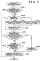
- FIG. 5 is a flowchart showing an abnormality diagnostic routine.
- the processes in this routine shown in the flowchart are repeated at predetermined cycles of time by the ECU 40.
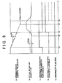
- FIG. 6 shows one example of change in the opening driving command value DEGR, the actual intake air quantity GN, an abnormality diagnostic execution flag XDIAGEX, and abnormality diagnostic complete flag XDIAG, and an abnormality flag XFAIL when the abnormality diagnostic routine shown in the flowchart is executed.
- the solid lines show the change in each of the values when there is no abnormality in the EGR mechanism 31 and the dashed lines show the change in each of the values when there is an abnormality in the EGR mechanism 31.
- the abnormality diagnostic routine according to this exemplary embodiment will be described with reference to FIGS. 5 and 6.
- This abnormality diagnostic execution flag XDIAGEX is set to "ON" when the following conditions (A) through (E) have all been fulfilled, for example.
- condition (C) the amount of change in the intake air quantity is equal to, or less than, a specific value
- condition (D) the opening of the throttle valve 20 is equal to, or greater than, a predetermined opening
- condition (E) the abnormality diagnostic complete flag XDIAG is "OFF".
- condition (A) it is determined that the vehicle is decelerating when the accelerator opening is "0" and the vehicle speed is equal to, or greater than, a predetermined speed.
- a fuel cut routine is being executed.
- this fuel cut routine is executed and engine combustion effectively stops, even if the flow control valve 34 is forcibly driven when the abnormality diagnostic routine is executed and the amount of recirculated exhaust gas differs from the amount optimal for the operating state of the engine, it is possible to suppress deterioration in the exhaust gas from that difference. Therefore, the aforementioned condition (A) is made one of the conditions for executing the abnormality diagnostic in the abnormality diagnostic routine.
- condition (B) is also made one of the conditions for executing the abnormality diagnostic.
- condition (C) is also made one of the conditions for executing the abnormality diagnostic.
- the aforementioned condition (D) is made one of the conditions for executing the abnormality diagnostic.
- the abnormality diagnostic is conducted when the flow control valve 34 is forcibly driven, when that diagnostic is being conducted, the amount of recirculated exhaust gas changes, if only temporarily, so that it differs from the amount optimal for the operating state of the engine. Therefore, it is preferable that the abnormality diagnostic be conducted in as short a time as possible and only when necessary. Therefore, in the abnormality diagnostic routine, by making condition (E) one of the conditions for executing the abnormality diagnostic, after confirming a positive diagnosis after engine startup, forced driving of the flow control valve 34 is immediately interrupted and the abnormality diagnostic routine is not executed again until the next engine startup. In this condition (E), the abnormality diagnostic complete flag XDIAG is reset to "OFF" when the engine is started, and is set to "ON" when a predetermined condition is fulfilled in the abnormality diagnostic routine.
- step S200 When it is determined that the condition for executing the abnormality diagnostic is fulfilled in step S200, i.e., when the abnormality diagnostic execution flag XDIAGEX is set to "ON” (i.e., YES in step S200), it is then determined whether the EGR insufficient flag XS is set to "ON” (step S210). If the EGR insufficient flag XS is set to "ON” (i.e., YES in step S210), an abnormality determining value KDGN is set to equal a first value KDGNS which corresponds to a case in which the exhaust gas recirculation characteristics of the EGR mechanism 31 are such that there is a tendency for the amount of recirculated exhaust gas to be insufficient (step S220).
- the abnormality determining value KDGN is set to a second value KDGNE which corresponds to a case in which there is not a tendency for the amount of recirculated exhaust gas from the EGR mechanism 31 to be insufficient (step S225).
- the first value KDGNS and the second value KDGNE related to the abnormality determining value KDGN are set beforehand to have the relationship shown in relational expression (1) below.
- the flow control valve 34 is then forcibly driven (step S230; timing 1 in FIG. 6). More specifically, the current opening driving command value DEGR set based on the operating state of the engine is used as the initial opening driving command value. A predetermined gradual change amount ⁇ k is then added to this opening driving command value DEGR and the sum is then set as the new opening driving command value DEGR, as shown by operational expression (2) below. [opening driving command value DEGR] ⁇ [current opening driving command value DEGR] + ⁇ k
- the gradual change amount ⁇ k can be set to either a positive or negative value.
- the opening driving command value DEGR gradually increases from the routine being repeatedly executed, and the opening of the flow control valve 34 also gradually increases due to that increase in the opening driving command value DEGR.
- the opening driving command value DEGR gradually decreases, resulting in the opening of the flow control valve 34 also gradually decreasing. Accordingly, the flow control valve 34 is forcibly driven in stages as the opening driving command value DEGR changes by the gradual change amount ⁇ k in this way.
- whether the gradual change amount ⁇ k is set to a positive value or a negative value i.e., whether the opening of the flow control valve 34 increases or decreases, is determined based on the opening of the flow control valve 34 when the forced driving is started.
- a predetermined opening ⁇ e.g. 50%
- the gradual change amount ⁇ k is set to a negative value so that the opening of the flow control valve 34 gradually decreases until the flow control valve 34 is fully closed.
- the gradual change amount ⁇ k is set to a positive value so that the opening of the flow control valve 34 gradually increases until the flow control valve 34 is fully open.
- the abnormality determining value KDGN is set based on the minimum amount of change in the opening driving command value DEGR. That is, when changing the opening of the flow control valve 34 from the predetermined opening ⁇ to fully closed, the amount of change in the opening driving command value DEGR is the minimum value, but the abnormality determining value KDGN is set to equal to, or less than, the amount of change DGN in the actual intake air quantity GN generated at this time.
- FIG. 6 shows an example of change in the opening driving command value DEGR when the opening driving command value DEGR gradually decreases due to the gradual change amount ⁇ k being set to a negative value such that the opening of the flow control valve 34 changes to the fully closed side.
- step S240 After the flow control valve 34 has been forcibly driven, it is then determined whether a predetermined period of time has elapsed after the flow control valve 34 has reached the fully open state or the fully closed state (step S240). If the predetermined period of time has not yet elapsed (i.e., NO in step S240), it is then determined whether the amount of change DGN in the actual intake air quantity GN exceeds the abnormality determining value KDGN (step S250).
- the abnormality diagnostic complete flag XDIAG is set to "ON" (step S270).
- the condition (E) is no longer fulfilled, which results in the condition for making a positive diagnosis no longer being fulfilled (i.e., abnormality diagnostic execution flag XDIAGEX is turned "OFF") (i.e., NO in step S200) so the routine ends. That is, in this case, because at least the abnormality diagnostic was conducted and a meaningful diagnosis was obtained, it is determined that it is unnecessary to continue with the processes thereafter in the abnormality diagnostic, so the routine ends. Accordingly, even if the flow control valve 34 has not yet reached a fully open or fully closed state, i.e., even if the forced driving of the flow control valve 34 is not yet complete, the forced driving is immediately interrupted and the abnormality diagnostic routine is no longer executed until the next engine startup. As a result, the abnormality diagnostic routine following the forced driving of the flow control valve 34 is executed for as short as time as possible and only when necessary.
- step S240 when it is determined in step S240 that the predetermined period of time has elapsed after the flow control valve 34 has reached the fully open or fully closed state (i.e., YES in step S240), it means that the flow control valve 34 has been forcibly driven to the fully open or fully closed state, and further, that a predetermined period of time (i.e., timing t4 to t5) has elapsed thereafter.
- a predetermined period of time i.e., timing t4 to t5
- the abnormality flag XFAIL is set to "ON" (step S260).
- the abnormality diagnostic complete flag XDIAG is then set to "ON" (step S270; timing t5).
- the ECU 40 waits for the abnormality flag XFAIL to be operated, i.e., waits for a positive diagnosis to be made, after the flow control valve 34 shifts to the fully open or fully closed state until the predetermined period of time passes.
- step S270 the abnormality diagnostic complete flag XDIAG is set to "ON" in step S270, or when it is determined in step S250 that the amount of change DGN is equal to, or less than, the abnormality determining value KDGN (i.e., NO in step S250), the routine ends.
- the ECU 40 monitors whether there is a tendency for the exhaust gas recirculation characteristics of the EGR mechanism 31 to deviate from the reference characteristics thereof, or more specifically, whether there is a tendency for the amount of recirculated exhaust gas to be insufficient, when the engine 10 is in a stable idling state.
- the diagnostic mode for the abnormality diagnostic of the EGR mechanism 31 is set based on the deviation tendency of the monitored exhaust gas recirculation characteristics.
- the diagnostic mode for the abnormality diagnostic also considering both the deviation tendency of exhaust gas recirculation characteristics obtained in advance, as well as the exhaust gas characteristics of the engine 10. Because the abnormality diagnostic of the EGR mechanism 31 is conducted based on the set diagnostic mode, it is possible to determine, both flexibly and appropriately, whether an abnormality exists according to the exhaust gas characteristics.
- the amount of change DGN in the actual intake air quantity GN is compared with the abnormality determining value KDGN. If the amount of change DGN must be equal to, or less than, the abnormality determining value KDGN, a positive diagnosis is made. Then, this condition for making a positive diagnosis (or more specifically, the abnormality determining value KDGN) is set variably based on whether there is a tendency for the amount of the recirculated exhaust gas of the EGR mechanism 31 to be insufficient.
- condition for making a positive diagnosis in the abnormality diagnostic can be set suitably according to the tendency of the amount of recirculated exhaust gas to be insufficient, so it is possible to determine, both flexibly and appropriately, whether an abnormality in the EGR control system 30 exists according to the exhaust gas characteristics.
- the engine 10 is provided with the NOx catalyst apparatus 15 in the exhaust gas passage 14, even if the amount of recirculated exhaust gas is insufficient, the engine 10 has exhaust gas characteristics in which an increase in the amount of NOx discharged as a result of the amount of recirculated exhaust gas being insufficient is limited to a range where it can essentially be ignored.
- the abnormality determining value KDGN is set equal to the first value KDGNS, thereby making the condition for making a positive diagnosis in the abnormality diagnostic more difficult to fulfill. Accordingly in this case, a positive diagnosis can be made more appropriately so excessive positive diagnoses can be avoided.
- the condition for making a positive diagnosis in the abnormality diagnostic is not made more difficult to fulfill and the abnormality determining value KDGN is set to equal the second value KDGNE which is larger than the first value KDGNS. Accordingly in this case, it is possible to quickly detect an abnormality and inhibit an increase in the amount of PM discharged.
- the predetermined value GNC1 set corresponding to the stable idling state is compared with the actual intake air quantity GN, and it is determined, based on the fact that the actual intake air quantity GN exceeds the predetermined value GNC1, that there is a tendency for the amount of recirculated exhaust gas to be insufficient. In this way, by detecting, based on the intake air quantity, that there is a tendency for the amount of the recirculated exhaust gas to be insufficient, that tendency can be determined relatively easily.
- the intake air quantity sensor 44 which is used when detecting the actual intake air quantity GN, is also used in the intake air quantity control and other controls in the engine 10 when conducting the abnormality diagnostic. As a result, the construction does not become complicated, as it does in the case where a flow sensor that detects the actual amount of recirculated exhaust gas is provided separately.
- the EGR mechanism 31 is forcibly driven and the abnormality determining value KDGN set based on the amount of change in the opening driving command value DEGR at that time is compared with the amount of change DGN in the actual intake air quantity GN.
- the amount of change DGN is equal to, or less than, the abnormality determining value KDGN, it is determined that there is an abnormality.
- the forced driving of the flow control valve 34 is divided into a plurality of stages. In each stage, the amount of change DGN in the actual intake air quantity GN and the abnormality determining value KDGN are compared.
- the forced driving of the flow control valve 34 is immediately interrupted by stopping the opening driving command value DEGR from changing in stages thereafter. Accordingly, the abnormality diagnostic routine that accompanies forced driving of the flow control valve 34 is executed for as short a time as possible and only when necessary. As a result, it is possible to avoid the forced driving being executed for longer than is necessary so that the period of time during which recirculated exhaust gas that is not suitable for the operating state of the engine is able to be limited to as short as possible.
- the condition for making a positive diagnosis is made more difficult to fulfill when there is a tendency for the amount of recirculated exhaust gas to be insufficient. Accordingly, when there is a tendency for the amount of recirculated exhaust gas to be insufficient, but that insufficiency is small so that it is not necessary to detect it as an abnormality, the abnormality diagnostic routine is able to be ended quickly so that the forced driving of the flow control valve 34 is able to be interrupted very early on. Accordingly, the foregoing effect is able to be made even more remarkable.
- the ECU 40 waits to set the EGR insufficient flag XS to "ON", i.e., waits to confirm the tendency for the amount of recirculated exhaust gas to be insufficient, until a predetermined period of time has elapsed after it has been determined that the actual intake air quantity GN exceeds the predetermined value GNC1. Therefore, even if the deviation tendency of the exhaust gas recirculation characteristics changes over time, adverse effects such as an erroneous determination of that deviation tendency due to such a change can be avoided. Accordingly, the monitoring of that deviation tendency of the exhaust gas recirculation characteristics can be conducted with even greater reliability.
- the deviation tendency of the exhaust gas recirculation characteristics is monitored. Accordingly, that monitoring is conducted when combustion is stable and the intake air quantity does not change much. Therefore, adverse effects from a change in the engine combustion state are avoided so the monitoring is able to be conducted with even greater reliability.
- Another condition for executing the abnormality diagnostic is that vehicle be decelerating, so the abnormality diagnostic is executed as a fuel cut routine is executed. Therefore, even if the flow control valve 34 is forcibly driven such that the amount of recirculated exhaust gas changes so that it differs from the amount optimal for the operating state of the engine, deterioration of the exhaust gas emissions due to that change is able to be suppressed to as great an extent as possible.
- another condition for executing the abnormality diagnostic is that opening of the throttle valve 20 be equal to, or greater than, a predetermined opening, such that the abnormality diagnostic is not executed when the opening of the throttle valve 20 is constricted so that the intake air quantity is extremely small. That is, the abnormality diagnostic is not executed when the change in the intake air quantity when the flow control valve 34 is forcibly driven is small and there is a possibility that an erroneous diagnosis may be made if the abnormality diagnosis is made based on such a small change. Accordingly, erroneous diagnoses are able to be avoided so the abnormality diagnosis is able to be made even more accurately.
- the EGR mechanism 31 is forcibly driven and the amount of change in the actual intake air pressure is compared with the abnormality determining value for the intake air pressure that is set based on the amount of change in the opening driving command value DEGR when the EGR mechanism 31 is forcibly driven.
- An abnormality is determined to exist when that amount of change is equal to, or less than, the abnormality determining value. Further, the abnormality determining value is set lower so that it is more difficult to make a positive diagnosis (i.e., a determination that an abnormality exists) when is has been determined based on the intake air pressure that there is a tendency for the amount of recirculated exhaust gas to be insufficient. On the other hand, when it has been determined that the amount of recirculated exhaust gas does not tend to be insufficient, the condition for making a positive diagnosis is not made more difficult to fulfill so an abnormality in the EGR mechanism 31 is determined quickly.
- step S110 shown in FIG. 2 it is determined whether the actual intake air quantity GN has shifted so that it is less than the predetermined value.
- an excessive recirculated exhaust gas amount flag (hereinafter, referred to simply as "EGR excessive flag") is set to "ON" (step S140).
- step S 110 when monitoring whether there is a tendency for the amount of recirculated exhaust gas to be excessive based on the intake air pressure, it is determined in step S 110 shown in FIG. 2 whether the actual intake air pressure has shifted so as to exceed the predetermined value.
- the EGR excessive flag is set to "ON" (step S140).
- step S210 in FIG. 5 i.e., ON in step S210
- the abnormality determining value is set to a value larger than normal (step S220).
- the abnormality diagnostic method described above is effective in flexibly and appropriately determining whether an abnormality exists in the EGR control system of the engine.
- the deviation tendency in the amount of recirculated exhaust gas is monitored on the condition that the engine 10 is in the stable idling state.
- that deviation tendency may also be monitored on the condition that the operating state of the engine 10 is stable and steady, i.e., when the engine 10 is operating in a state where the intake air quantity and the intake air pressure can be regarded as being substantially constant, such as when the vehicle is running at low speeds.
- the actual intake air quantity or the amount of change in the intake air pressure are compared with the respective predetermined value and it is determined whether there is a tendency for the amount of recirculated exhaust gas to be insufficient or excessive.
- the condition for making a positive diagnosis is then made more difficult to fulfill based on that result.
- a process to inhibit a positive diagnosis from being made may also be executed as described below.
- the positive diagnosis itself may also be prohibited when it is determined that the tendency is small.
- the actual intake air quantity GN is less than the predetermined value GNC1 but exceeds the upper limit value GNC0 of the actual intake air quantity GN, it can be determined that there is a tendency for the amount of the recirculated exhaust gas to be insufficient. Further, when there is a tendency for the amount of the recirculated exhaust gas to be excessive, it can be determined that the degree of that tendency is small when the actual intake air quantity GN is less than a lower limit value corresponding to the stable idling state but the degree of deviation from that lower limit value is small. Also, with the intake air pressure, as well, the same determination can be made by the same method, with the exception of the point where the tendency for the amount of recirculated exhaust gas to be insufficient increases the lower the intake air pressure.
- the elapsed time counter value C is increased by a specific increment in step S120 in FIG. 2.
- the amount of the increment may also be set according to the degree of deviation of the actual intake air quantity or the actual intake air pressure from the respective predetermined value. For example, taking an example in which the tendency for the amount of the recirculated exhaust gas to be insufficient is monitored, the amount of the increment is set larger the more the actual air intake quantity exceeds the predetermined value, for example. Similarly, the amount of the increment is set larger the more the actual intake air pressure falls below the predetermined value. In this way, by increasing the amount of the increment the larger the degree of the deviation, it is possible to appropriately and quickly detect the tendency of the amount of recirculated exhaust gas to be insufficient or excessive according to those tendencies.
- the object to which the abnormality diagnostic method according to the invention is applied is by no means limited to an engine provided with the NOx catalyst apparatus 15, for example.
- the object of the abnormality diagnostic may, for example, also be the EGR control system mounted in an engine provided with a PM filter in the exhaust system.
- the EGR system which is the object of the abnormality diagnostic is not limited to being mounted in a diesel engine, but may also be mounted in an in-cylinder injection type gasoline engine in which fuel is directly injected into the combustion chamber, or other type of internal combustion engine.
- the monitoring step includes a tendency determining step for comparing the actual amount of recirculated exhaust gas with the predetermined value and determining that a third tendency, in which the actual amount of recirculated exhaust gas exceeds the predetermined value, exists as the deviation tendency
- the positive diagnosis condition varying step includes a condition tightening step for tightening the condition for making a positive diagnosis (i.e., making the condition more difficult to fulfill) such that it is more difficult to make a positive diagnosis (i.e., a diagnosis or determination that an abnormality exists) when it has been determined in the determination step that the third tendency exits.
- the actual amount of recirculated exhaust gas is first compared with the predetermined value set based on the predetermined operating state of the engine, and it is then determined based on that comparison whether there is a tendency (i.e., the third tendency) for the actual amount of recirculated exhaust gas to exceed the predetermined value (i.e., the tendency determining step).
- the predetermined value i.e., the third tendency
- the condition for making a positive diagnosis when conducting the abnormality diagnostic is made more difficult to fulfill so that it is more difficult to make a positive diagnosis (i.e., the condition tightening step). Accordingly, even if the amount of recirculated exhaust gas is excessive, in an engine having exhaust gas characteristics in which an increase in the amount of PM discharged due to that excessive amount of recirculated exhaust gas is kept within a range in which it can essentially be ignored, excessive positive diagnoses can be avoided so that abnormalities can be diagnosed appropriately when diagnosing an abnormality in the EGR control system.
- the condition for making a positive diagnosis when determining whether an abnormality exists may also be set, in advance, so that it is more difficult for a positive diagnosis to be made, and changed to make it easier to make a positive diagnosis when it has been determined that a tendency in which the actual amount of recirculated exhaust gas falls below the predetermined value exists as the deviation tendency, with effectively the same results. That is, with this construction as well, effects similar to those of the invention described in (a) above are able to be obtained.
- the abnormality diagnostic executing step includes a forced driving step for forcibly driving the EGR mechanism by forcibly changing a driving command value, and a positive diagnosis determining step for determining that there is an abnormality in the EGR mechanism when the amount of change in the actual intake air quantity generated by that forced driving is equal to, or less than, a predetermined determining value set based on the amount of change in the driving command value.
- the condition tightening step includes a step for changing the predetermined determining value so as to become smaller when it has been determined in the tendency determining step that the third tendency exists than when it has been determined in the tendency determining step that the third tendency does not exist.
- the forced driving step includes a step for gradually changing the driving command value in order to perform the forced driving in a plurality of stages when forcibly driving the EGR mechanism.
- the abnormality diagnostic executing step includes a step for interrupting forced driving of the EGR mechanism by stopping the driving command value from changing in a stage after the presence or absence of an abnormality in the EGR mechanism has been determined based on the comparison between the predetermined determining value and the amount of change in the actual intake air quantity.
- the actual intake air pressure when the internal combustion engine is in the predetermined operating state is compared with the predetermined value set based on that predetermined operating state of the engine, and it is determined that the third tendency exists when the actual intake air pressure exceeds the predetermined value.
- the abnormality diagnostic executing step includes a forced driving step for forcibly driving the EGR mechanism by forcibly changing a driving command value, and a positive diagnosis determining step for determining that there is an abnormality in the EGR mechanism when the amount of change in the actual intake air pressure generated by that forced driving is equal to, or less than, a predetermined determining value set based on the amount of change in the driving command value.
- the condition tightening step includes a step for changing the predetermined determining value so as to become smaller when it has been determined in the tendency determining step that the third tendency exists than when it has been determined in the tendency determining step that the third tendency does not exist.
- the forced driving step includes a step for gradually changing the driving command value in order to perform the forced driving in a plurality of stages when forcibly driving the EGR mechanism.
- the abnormality diagnostic executing step includes a step for interrupting forced driving of the EGR mechanism by stopping the driving command value from changing in a stage after the presence or absence of an abnormality in the EGR mechanism has been determined based on a comparison between the predetermined determining value and the amount of change in the actual intake air pressure.
- the characteristic that exists between either the intake air quantity and the amount of the recirculated exhaust gas or the intake air pressure and the amount of recirculated exhaust gas is used. Therefore, it is possible to determine relatively easily that the third tendency exists based either on the fact that the actual intake air quantity is below the predetermined value set based on the predetermined operating state of the engine, or on the fact that the actual intake air pressure exceeds the predetermined value set based on the predetermined operating state of the engine.
- the abnormality diagnostic is not performed based on a uniform condition for making a positive diagnosis; rather, the condition for a making positive diagnosis is made more difficult to fulfill when there is a tendency for the actual amount of the recirculated exhaust gas to be excessive.
- the determining value is set smaller when determining whether an abnormality exists based on either a determination that the actual intake air quantity during the predetermined operating state of the engine is below the predetermined value, or a determination that the actual intake air pressure during the predetermined operating state of the engine exceeds the predetermined value. Therefore, even if the actual amount of recirculated exhaust gas corresponding to the amount of change in the driving command value exceeds the original reference value of the EGR mechanism, it is not diagnosed as an abnormality when that tendency is slight.
- the forced driving of the EGR mechanism is performed in a plurality of stages. Then, when it has been determined that no abnormality exists in the EGR mechanism in any of the plurality of stages, the forced driving of the EGR mechanism is interrupted by stopping the driving command value from changing in the stages thereafter. Accordingly, it is possible to avoid forcibly driving the EGR mechanism for longer than necessary such that the period during which exhaust gas recirculation not suitably for the operating state of the engine can be made as short as possible.
- the diagnostic mode setting step includes a positive diagnosis prohibiting step for prohibiting a positive diagnosis of the EGR mechanism when it is determined in the tendency determining step that the fourth tendency exists.
- the deviation tendency is the fourth tendency and this is taken into consideration along with the exhaust gas characteristics of the internal combustion engine
- a positive diagnosis is prohibited from being made for the EGR mechanism when, for example, that tendency poses no problem in terms of the deterioration of the exhaust gas such as an increase in the amount of PM discharged. Accordingly, it is possible to avoid the original function of the EGR control system, which is to purify exhaust gas, from being stopped or restricted due to unnecessary positive diagnoses being made.
- a control unit for an exhaust gas recirculation control system compares an actual intake air quantity GN with a predetermined quantity GNC1 when an engine is in a stable idling state (steps S100, S 110). Then, presuming there is a tendency for the amount of recirculated exhaust gas from the exhaust gas recirculation control system to be less than a reference amount corresponding to the stable idling state, a recirculated exhaust gas insufficient flag XS is set to "ON" (step S140) after the actual intake air quantity GN has exceeded the predetermined quantity GNC1 for a predetermined period of time (steps S120, S13Q). The control unit then makes a condition for making a positive diagnosis more difficult to fulfill so that it is more difficult to make a positive diagnosis when the recirculated exhaust gas insufficient flag XS is set to "ON.”
Landscapes
- Engineering & Computer Science (AREA)
- Chemical & Material Sciences (AREA)
- Combustion & Propulsion (AREA)
- Mechanical Engineering (AREA)
- General Engineering & Computer Science (AREA)
- Physics & Mathematics (AREA)
- Electromagnetism (AREA)
- Exhaust-Gas Circulating Devices (AREA)
- Output Control And Ontrol Of Special Type Engine (AREA)
- Combined Controls Of Internal Combustion Engines (AREA)
Abstract
Description
driving command value DEGR] + Δk
Claims (15)
- An abnormality diagnostic method for an exhaust gas recirculation control system provided with an exhaust gas recirculation mechanism that returns some of an exhaust gas flowing through an exhaust gas passage of an internal combustion engine to an intake air passage, the exhaust gas recirculation control system controlling an amount of recirculated exhaust gas by driving the exhaust gas recirculation mechanism based on an operating state of the engine, the abnormality diagnostic method characterised by comprising:a monitoring step for monitoring a tendency of exhaust gas recirculation characteristics of the exhaust gas recirculation mechanism when the internal combustion engine is in a predetermined operating state to deviate from reference characteristics thereof before conducting an abnormality diagnostic of the exhaust gas recirculation mechanism;a diagnostic mode setting step for setting a diagnostic mode for the abnormality diagnostic of the exhaust gas recirculation mechanism, based on the monitored deviation tendency of the exhaust gas recirculation characteristics; andan abnormality diagnostic executing step for executing the abnormality diagnostic based on the set diagnostic mode.
- The abnormality diagnostic method according to claim 1, characterised in that the monitoring step includes a step for obtaining the deviation tendency of the exhaust gas recirculation characteristics of the exhaust gas recirculation mechanism based on results of a comparison between an actual amount of recirculated exhaust gas and a predetermined value set based on the predetermined operating state of the engine.
- The abnormality diagnostic method according to claim 2, characterised in that the diagnostic mode setting step includes a positive diagnosis condition varying step for variably setting, based on the results of the comparison between the actual amount of recirculated exhaust gas and the predetermined value obtained in the monitoring step, a condition for making a positive diagnosis for determining in the abnormality diagnostic executing step that there is an abnormality in the exhaust gas recirculation mechanism.
- The abnormality diagnostic method according to claim 3, characterized in that:the monitoring step includes a tendency determining step for comparing the actual amount of recirculated exhaust gas with the predetermined value and determining whether a first tendency, in which the actual amount of recirculated exhaust gas is below the predetermined value, exists as the deviation tendency, andthe positive diagnosis condition varying step includes a condition tightening step for making a condition for making a positive diagnosis more difficult to be fulfilled so that it is more difficult for a positive diagnosis to be made when it is determined in the tendency determining step that the first tendency exists.
- The abnormality diagnostic method according to claim 4, characterized in that, in the tendency determining step, the actual intake air quantity when the internal combustion engine is in the predetermined operating state is compared with the predetermined value set based on the predetermined operating state of the engine, and it is determined that the first tendency exists when the actual intake air quantity exceeds the predetermined value.
- The abnormality diagnostic method according to claim 5, characterized in that:the abnormality diagnostic executing step includes a forced driving step for forcibly driving the exhaust gas recirculation mechanism by forcibly changing a driving command value which drives the exhaust gas recirculation mechanism, and a positive diagnosis determining step for determining that there is an abnormality in the exhaust gas recirculation mechanism when an amount of change in the actual intake air quantity generated by that forced driving is equal to, or less than, a predetermined determining value set based on an amount of change in the driving command value, andthe condition tightening step includes a step for changing the predetermined determining value so as to become smaller when it has been determined in the tendency determining step that the first tendency exists than when it has been determined in the tendency determining step that the first tendency does not exist.
- The abnormality diagnostic method according to claim 6, characterised in that:the forced driving step includes a step for gradually changing the driving command value in order to perform the forced driving in a plurality of stages when forcibly driving the exhaust gas recirculation mechanism, andthe abnormality diagnostic executing step includes a step for interrupting the forced driving of the exhaust gas recirculation mechanism by stopping the driving command value from changing in a stage after the presence or absence of an abnormality in the exhaust gas recirculation mechanism has been determined based on the comparison between the predetermined determining value and the amount of change in the actual intake air quantity.
- The abnormality diagnostic method according to claim 4, characterised in that, in the tendency determining step, an actual intake air pressure when the internal combustion engine is in the predetermined operating state is compared with a predetermined value set based on that predetermined operating state of the engine, and it is determined that the first tendency exists when the actual intake air pressure is below the predetermined value.
- The abnormality diagnostic method according to claim 8, characterised in that:the abnormality diagnostic executing step includes a forced driving step for forcibly driving the exhaust gas recirculation mechanism by forcibly changing a driving command value, and a positive diagnosis determining step for determining that there is an abnormality in the exhaust gas recirculation mechanism when an amount of change in the actual intake air pressure generated by that forced driving is equal to, or less than, a predetermined determining value set based on an amount of change in the driving command value, andthe condition tightening step includes a step for changing the predetermined determining value so as to become smaller when it has been determined in the tendency determining step that the first tendency exists than when it has been determined in the tendency determining step that the first tendency does not exist.
- The abnormality diagnostic method according to claim 9, characterised in that:the forced driving step includes a step for gradually changing the driving command value in order to perform the forced driving in a plurality of stages when forcibly driving the exhaust gas recirculation mechanism, andthe abnormality diagnostic executing step includes a step for interrupting the forced driving of the exhaust gas recirculation mechanism by stopping the driving command value from changing in a stage after the presence or absence of an abnormality in the exhaust gas recirculation mechanism has been determined based on the comparison between the predetermined determining value and the amount of change in the actual intake air pressure.
- The abnormality diagnostic method according to any one of claims 4 to 10, characterised in that:in the tendency determining step, it is further determined whether a second tendency, in which a degree thereof is smaller than that of the first tendency, exists as the deviation tendency, andthe diagnostic mode setting step includes a positive diagnosis prohibiting step for prohibiting a positive diagnosis of the exhaust gas recirculation mechanism when it is determined in the tendency determining step that the second tendency exists.
- The abnormality diagnostic method according to any one of claims 1 to 11, characterised in that, in the tendency determining step, the deviation tendency relating to the exhaust gas recirculation characteristics is confirmed when that deviation tendency continues uniformly for a predetermined period of time.
- The abnormality diagnostic method according to claim 12, characterised in that the predetermined period of time is set based on at least one of either the actual intake air quantity or the intake air pressure.
- The abnormality diagnostic method according to any one of claims 1 to 13, characterised in that, in the monitoring step, the deviation tendency is monitored when the internal combustion engine is in a stable idling state as the predetermined operating state of the engine.
- The abnormality diagnostic method according to any one of claims 1 to 13, characterised in that, in the monitoring step, the deviation tendency is monitored when the predetermined operating state of the engine is such that at least one of at least the intake air quantity and the intake air pressure of the internal combustion engine is constant.
Applications Claiming Priority (2)
| Application Number | Priority Date | Filing Date | Title |
|---|---|---|---|
| JP2002151262A JP3937926B2 (en) | 2002-05-24 | 2002-05-24 | Abnormality judgment method of exhaust gas recirculation control device |
| JP2002151262 | 2002-05-24 |
Publications (3)
| Publication Number | Publication Date |
|---|---|
| EP1365139A2 true EP1365139A2 (en) | 2003-11-26 |
| EP1365139A3 EP1365139A3 (en) | 2003-12-17 |
| EP1365139B1 EP1365139B1 (en) | 2005-04-20 |
Family
ID=29397971
Family Applications (1)
| Application Number | Title | Priority Date | Filing Date |
|---|---|---|---|
| EP03011624A Expired - Lifetime EP1365139B1 (en) | 2002-05-24 | 2003-05-22 | Abnormality diagnostic method for exhaust gas recirculation control system |
Country Status (4)
| Country | Link |
|---|---|
| EP (1) | EP1365139B1 (en) |
| JP (1) | JP3937926B2 (en) |
| DE (1) | DE60300517T2 (en) |
| ES (1) | ES2240884T3 (en) |
Cited By (8)
| Publication number | Priority date | Publication date | Assignee | Title |
|---|---|---|---|---|
| WO2008152037A1 (en) * | 2007-06-12 | 2008-12-18 | Continental Automotive Gmbh | Method and device for monitoring an exhaust gas recirculation system and computer program |
| WO2009118605A1 (en) * | 2008-03-28 | 2009-10-01 | Toyota Jidosha Kabushiki Kaisha | Abnormality diagnosis apparatus for exhaust gas recirculation apparatus and abnormality diagnosis method for exhaust gas recirculation apparatus |
| WO2009130563A1 (en) * | 2008-04-21 | 2009-10-29 | Toyota Jidosha Kabushiki Kaisha | Diagnostic apparatus and diagnostic method for exhaust gas recirculation system |
| US8397700B2 (en) | 2007-12-14 | 2013-03-19 | Toyota Jidosha Kabushiki Kaisha | Abnormality diagnosis device for exhaust gas recirculation device |
| WO2014188246A1 (en) * | 2013-05-20 | 2014-11-27 | Toyota Jidosha Kabushiki Kaisha | Control apparatus and control method for internal combustion engine |
| EP2780685A4 (en) * | 2011-11-14 | 2015-07-22 | Scania Cv Ab | Method and system for regulating a combustion engine |
| EP3441604A4 (en) * | 2016-04-04 | 2019-03-13 | Isuzu Motors Limited | Abnormality detection device, abnormality detection method, and abnormality detection system |
| CN113703381A (en) * | 2021-10-29 | 2021-11-26 | 四川高诚物联网科技有限公司 | Gas alarm safety data acquisition method and terminal based on Internet of things |
Families Citing this family (4)
| Publication number | Priority date | Publication date | Assignee | Title |
|---|---|---|---|---|
| DE102007009689B4 (en) * | 2007-02-28 | 2017-10-19 | Robert Bosch Gmbh | Method for operating an internal combustion engine with exhaust gas recirculation |
| JP2009275653A (en) * | 2008-05-16 | 2009-11-26 | Honda Motor Co Ltd | Abnormality determining device of idle control system |
| JP5321200B2 (en) * | 2009-03-31 | 2013-10-23 | トヨタ自動車株式会社 | Abnormality diagnosis device for exhaust gas recirculation system |
| JP2014034921A (en) * | 2012-08-08 | 2014-02-24 | Denso Corp | Control device of internal combustion engine |
Family Cites Families (5)
| Publication number | Priority date | Publication date | Assignee | Title |
|---|---|---|---|---|
| FR2698407B1 (en) * | 1992-11-24 | 1994-12-30 | Renault | Method for controlling the exhaust gas recirculation system of an internal combustion engine. |
| JPH08226354A (en) * | 1995-02-20 | 1996-09-03 | Unisia Jecs Corp | Diagnostic device for exhaust gas recirculation system of internal combustion engine |
| US6024075A (en) * | 1998-06-29 | 2000-02-15 | Ford Global Technologies, Inc. | Engine control system with exhaust gas recirculation and method for determining proper functioning of the EGR system in an automotive engine |
| DE60029474T2 (en) * | 1999-12-09 | 2007-02-15 | International Engine Intellectual Property Company, LLC., Warrenville | An event monitoring system in an exhaust gas recirculation system of an internal combustion engine |
| US6363922B1 (en) * | 2000-10-11 | 2002-04-02 | Detroit Diesel Corp | Exhaust gas recirculation pressure differential sensor error compensation |
-
2002
- 2002-05-24 JP JP2002151262A patent/JP3937926B2/en not_active Expired - Fee Related
-
2003
- 2003-05-22 DE DE60300517T patent/DE60300517T2/en not_active Expired - Lifetime
- 2003-05-22 EP EP03011624A patent/EP1365139B1/en not_active Expired - Lifetime
- 2003-05-22 ES ES03011624T patent/ES2240884T3/en not_active Expired - Lifetime
Cited By (13)
| Publication number | Priority date | Publication date | Assignee | Title |
|---|---|---|---|---|
| CN101680383B (en) * | 2007-06-12 | 2012-12-05 | 欧陆汽车有限责任公司 | Method and device for monitoring exhaust gas recirculation system |
| US8843322B2 (en) | 2007-06-12 | 2014-09-23 | Continental Automotive Gmbh | Method and device for monitoring an exhaust gas recirculation system and computer program |
| WO2008152037A1 (en) * | 2007-06-12 | 2008-12-18 | Continental Automotive Gmbh | Method and device for monitoring an exhaust gas recirculation system and computer program |
| US8397700B2 (en) | 2007-12-14 | 2013-03-19 | Toyota Jidosha Kabushiki Kaisha | Abnormality diagnosis device for exhaust gas recirculation device |
| US20110011378A1 (en) * | 2008-03-28 | 2011-01-20 | Toyota Jidosha Kabushiki Kaisha | Abnormality diagnosis apparatus for exhaust gas recirculation apparatus and abnormality diagnosis method for exhaust gas recirculation apparatus |
| WO2009118605A1 (en) * | 2008-03-28 | 2009-10-01 | Toyota Jidosha Kabushiki Kaisha | Abnormality diagnosis apparatus for exhaust gas recirculation apparatus and abnormality diagnosis method for exhaust gas recirculation apparatus |
| WO2009130563A1 (en) * | 2008-04-21 | 2009-10-29 | Toyota Jidosha Kabushiki Kaisha | Diagnostic apparatus and diagnostic method for exhaust gas recirculation system |
| EP2780685A4 (en) * | 2011-11-14 | 2015-07-22 | Scania Cv Ab | Method and system for regulating a combustion engine |
| WO2014188246A1 (en) * | 2013-05-20 | 2014-11-27 | Toyota Jidosha Kabushiki Kaisha | Control apparatus and control method for internal combustion engine |
| CN105209742A (en) * | 2013-05-20 | 2015-12-30 | 丰田自动车株式会社 | Control apparatus and control method for internal combustion engine |
| US20160108858A1 (en) * | 2013-05-20 | 2016-04-21 | Toyota Jidosha Kabushiki Kaisha | Control apparatus and control method for internal combustion engine |
| EP3441604A4 (en) * | 2016-04-04 | 2019-03-13 | Isuzu Motors Limited | Abnormality detection device, abnormality detection method, and abnormality detection system |
| CN113703381A (en) * | 2021-10-29 | 2021-11-26 | 四川高诚物联网科技有限公司 | Gas alarm safety data acquisition method and terminal based on Internet of things |
Also Published As
| Publication number | Publication date |
|---|---|
| EP1365139B1 (en) | 2005-04-20 |
| JP3937926B2 (en) | 2007-06-27 |
| EP1365139A3 (en) | 2003-12-17 |
| DE60300517T2 (en) | 2006-02-23 |
| DE60300517D1 (en) | 2005-05-25 |
| ES2240884T3 (en) | 2005-10-16 |
| JP2003343361A (en) | 2003-12-03 |
Similar Documents
| Publication | Publication Date | Title |
|---|---|---|
| US7275525B2 (en) | Control apparatus for an internal combustion engine | |
| US5513616A (en) | Method for determining a failure of an EGR apparatus | |
| US9458776B2 (en) | Abnormality diagnosis device and an abnormality diagnosis method for a variable valve mechanism | |
| USRE50153E1 (en) | EGR apparatus of engine | |
| US5542400A (en) | Apparatus and method for determining a failure of an EGR apparatus | |
| US10982604B2 (en) | Gasoline engine system with improved idle up control upon detecting abnormality in valve during deceleration | |
| JPH0835449A (en) | Failure detection device for exhaust gas recirculation control device | |
| EP1365139B1 (en) | Abnormality diagnostic method for exhaust gas recirculation control system | |
| US10927778B2 (en) | Engine system | |
| EP2674597A1 (en) | Control device for internal combustion engine | |
| US10995686B2 (en) | Evaporated fuel treatment device | |
| JP4687663B2 (en) | Abnormality diagnosis device for exhaust gas recirculation system | |
| JP4862681B2 (en) | Control device for internal combustion engine | |
| EP0812984B1 (en) | A malfunction determining apparatus of an exhaust gas recirculation system | |
| JP5169497B2 (en) | Exhaust device failure diagnosis method and apparatus | |
| JPH04140464A (en) | Trouble diagnosing device for exhaust gas recirculating device | |
| EP1517030B1 (en) | Method and apparatus for detecting deterioration in fuel injection amount of internal combustion engine | |
| CN113474548B (en) | Engine EGR device | |
| JP3651810B2 (en) | Failure diagnosis device for exhaust gas recirculation device of internal combustion engine | |
| JP2003129906A (en) | Abnormality diagnosis device for exhaust gas recirculation system | |
| JP4736978B2 (en) | Exhaust gas recirculation device for internal combustion engine | |
| WO2025023012A1 (en) | Failure detection device for exhaust gas recirculation device | |
| JP4186517B2 (en) | Device for detecting clogging of an air cleaner for an internal combustion engine | |
| JP3632446B2 (en) | EGR control device for internal combustion engine | |
| JP4839267B2 (en) | Fuel injection control device for diesel engine |
Legal Events
| Date | Code | Title | Description |
|---|---|---|---|
| PUAI | Public reference made under article 153(3) epc to a published international application that has entered the european phase |
Free format text: ORIGINAL CODE: 0009012 |
|
| PUAL | Search report despatched |
Free format text: ORIGINAL CODE: 0009013 |
|
| 17P | Request for examination filed |
Effective date: 20030522 |
|
| AK | Designated contracting states |
Kind code of ref document: A2 Designated state(s): AT BE BG CH CY CZ DE DK EE ES FI FR GB GR HU IE IT LI LU MC NL PT RO SE SI SK TR |
|
| AX | Request for extension of the european patent |
Extension state: AL LT LV MK |
|
| AK | Designated contracting states |
Kind code of ref document: A3 Designated state(s): AT BE BG CH CY CZ DE DK EE ES FI FR GB GR HU IE IT LI LU MC NL PT RO SE SI SK TR |
|
| AX | Request for extension of the european patent |
Extension state: AL LT LV MK |
|
| 17Q | First examination report despatched |
Effective date: 20040218 |
|
| AKX | Designation fees paid |
Designated state(s): DE ES FR GB IT |
|
| GRAP | Despatch of communication of intention to grant a patent |
Free format text: ORIGINAL CODE: EPIDOSNIGR1 |
|
| GRAA | (expected) grant |
Free format text: ORIGINAL CODE: 0009210 |
|
| GRAS | Grant fee paid |
Free format text: ORIGINAL CODE: EPIDOSNIGR3 |
|
| AK | Designated contracting states |
Kind code of ref document: B1 Designated state(s): DE ES FR GB IT |
|
| REG | Reference to a national code |
Ref country code: GB Ref legal event code: FG4D |
|
| REG | Reference to a national code |
Ref country code: IE Ref legal event code: FG4D |
|
| REF | Corresponds to: |
Ref document number: 60300517 Country of ref document: DE Date of ref document: 20050525 Kind code of ref document: P |
|
| REG | Reference to a national code |
Ref country code: ES Ref legal event code: FG2A Ref document number: 2240884 Country of ref document: ES Kind code of ref document: T3 |
|
| ET | Fr: translation filed | ||
| PLBE | No opposition filed within time limit |
Free format text: ORIGINAL CODE: 0009261 |
|
| STAA | Information on the status of an ep patent application or granted ep patent |
Free format text: STATUS: NO OPPOSITION FILED WITHIN TIME LIMIT |
|
| 26N | No opposition filed |
Effective date: 20060123 |
|
| REG | Reference to a national code |
Ref country code: GB Ref legal event code: 746 Effective date: 20111114 |
|
| REG | Reference to a national code |
Ref country code: DE Ref legal event code: R084 Ref document number: 60300517 Country of ref document: DE Effective date: 20111109 |
|
| REG | Reference to a national code |
Ref country code: FR Ref legal event code: PLFP Year of fee payment: 14 |
|
| REG | Reference to a national code |
Ref country code: FR Ref legal event code: PLFP Year of fee payment: 15 |
|
| PGFP | Annual fee paid to national office [announced via postgrant information from national office to epo] |
Ref country code: FR Payment date: 20170413 Year of fee payment: 15 Ref country code: GB Payment date: 20170517 Year of fee payment: 15 Ref country code: DE Payment date: 20170516 Year of fee payment: 15 |
|
| PGFP | Annual fee paid to national office [announced via postgrant information from national office to epo] |
Ref country code: ES Payment date: 20170605 Year of fee payment: 15 Ref country code: IT Payment date: 20170522 Year of fee payment: 15 |
|
| REG | Reference to a national code |
Ref country code: DE Ref legal event code: R119 Ref document number: 60300517 Country of ref document: DE |
|
| GBPC | Gb: european patent ceased through non-payment of renewal fee |
Effective date: 20180522 |
|
| PG25 | Lapsed in a contracting state [announced via postgrant information from national office to epo] |
Ref country code: FR Free format text: LAPSE BECAUSE OF NON-PAYMENT OF DUE FEES Effective date: 20180531 Ref country code: GB Free format text: LAPSE BECAUSE OF NON-PAYMENT OF DUE FEES Effective date: 20180522 Ref country code: DE Free format text: LAPSE BECAUSE OF NON-PAYMENT OF DUE FEES Effective date: 20181201 Ref country code: IT Free format text: LAPSE BECAUSE OF NON-PAYMENT OF DUE FEES Effective date: 20180522 |
|
| REG | Reference to a national code |
Ref country code: ES Ref legal event code: FD2A Effective date: 20190913 |
|
| PG25 | Lapsed in a contracting state [announced via postgrant information from national office to epo] |
Ref country code: ES Free format text: LAPSE BECAUSE OF NON-PAYMENT OF DUE FEES Effective date: 20180523 |