EP1364822A1 - Wing opening/closing device for trucks or the like - Google Patents
Wing opening/closing device for trucks or the like Download PDFInfo
- Publication number
- EP1364822A1 EP1364822A1 EP02715746A EP02715746A EP1364822A1 EP 1364822 A1 EP1364822 A1 EP 1364822A1 EP 02715746 A EP02715746 A EP 02715746A EP 02715746 A EP02715746 A EP 02715746A EP 1364822 A1 EP1364822 A1 EP 1364822A1
- Authority
- EP
- European Patent Office
- Prior art keywords
- wing door
- door opening
- spring
- closing
- link member
- Prior art date
- Legal status (The legal status is an assumption and is not a legal conclusion. Google has not performed a legal analysis and makes no representation as to the accuracy of the status listed.)
- Withdrawn
Links
- 230000006835 compression Effects 0.000 description 8
- 238000007906 compression Methods 0.000 description 8
- 230000002401 inhibitory effect Effects 0.000 description 3
- 238000012423 maintenance Methods 0.000 description 3
- 230000004048 modification Effects 0.000 description 2
- 238000012986 modification Methods 0.000 description 2
- 230000000717 retained effect Effects 0.000 description 2
- 230000002441 reversible effect Effects 0.000 description 2
- 230000001133 acceleration Effects 0.000 description 1
- 230000001154 acute effect Effects 0.000 description 1
- 230000008602 contraction Effects 0.000 description 1
Images


Classifications
-
- B—PERFORMING OPERATIONS; TRANSPORTING
- B60—VEHICLES IN GENERAL
- B60J—WINDOWS, WINDSCREENS, NON-FIXED ROOFS, DOORS, OR SIMILAR DEVICES FOR VEHICLES; REMOVABLE EXTERNAL PROTECTIVE COVERINGS SPECIALLY ADAPTED FOR VEHICLES
- B60J7/00—Non-fixed roofs; Roofs with movable panels, e.g. rotary sunroofs
- B60J7/08—Non-fixed roofs; Roofs with movable panels, e.g. rotary sunroofs of non-sliding type, i.e. movable or removable roofs or panels, e.g. let-down tops or roofs capable of being easily detached or of assuming a collapsed or inoperative position
-
- B—PERFORMING OPERATIONS; TRANSPORTING
- B60—VEHICLES IN GENERAL
- B60J—WINDOWS, WINDSCREENS, NON-FIXED ROOFS, DOORS, OR SIMILAR DEVICES FOR VEHICLES; REMOVABLE EXTERNAL PROTECTIVE COVERINGS SPECIALLY ADAPTED FOR VEHICLES
- B60J5/00—Doors
- B60J5/04—Doors arranged at the vehicle sides
- B60J5/0497—Doors arranged at the vehicle sides for load transporting vehicles or public transport, e.g. lorries, trucks, buses
- B60J5/0498—Doors arranged at the vehicle sides for load transporting vehicles or public transport, e.g. lorries, trucks, buses with rigid panels pivoting about a horizontal axis
-
- E—FIXED CONSTRUCTIONS
- E05—LOCKS; KEYS; WINDOW OR DOOR FITTINGS; SAFES
- E05F—DEVICES FOR MOVING WINGS INTO OPEN OR CLOSED POSITION; CHECKS FOR WINGS; WING FITTINGS NOT OTHERWISE PROVIDED FOR, CONCERNED WITH THE FUNCTIONING OF THE WING
- E05F1/00—Closers or openers for wings, not otherwise provided for in this subclass
- E05F1/08—Closers or openers for wings, not otherwise provided for in this subclass spring-actuated, e.g. for horizontally sliding wings
- E05F1/10—Closers or openers for wings, not otherwise provided for in this subclass spring-actuated, e.g. for horizontally sliding wings for swinging wings, e.g. counterbalance
- E05F1/1041—Closers or openers for wings, not otherwise provided for in this subclass spring-actuated, e.g. for horizontally sliding wings for swinging wings, e.g. counterbalance with a coil spring perpendicular to the pivot axis
- E05F1/105—Closers or openers for wings, not otherwise provided for in this subclass spring-actuated, e.g. for horizontally sliding wings for swinging wings, e.g. counterbalance with a coil spring perpendicular to the pivot axis with a compression spring
- E05F1/1058—Closers or openers for wings, not otherwise provided for in this subclass spring-actuated, e.g. for horizontally sliding wings for swinging wings, e.g. counterbalance with a coil spring perpendicular to the pivot axis with a compression spring for counterbalancing
-
- E—FIXED CONSTRUCTIONS
- E05—LOCKS; KEYS; WINDOW OR DOOR FITTINGS; SAFES
- E05Y—INDEXING SCHEME ASSOCIATED WITH SUBCLASSES E05D AND E05F, RELATING TO CONSTRUCTION ELEMENTS, ELECTRIC CONTROL, POWER SUPPLY, POWER SIGNAL OR TRANSMISSION, USER INTERFACES, MOUNTING OR COUPLING, DETAILS, ACCESSORIES, AUXILIARY OPERATIONS NOT OTHERWISE PROVIDED FOR, APPLICATION THEREOF
- E05Y2900/00—Application of doors, windows, wings or fittings thereof
- E05Y2900/50—Application of doors, windows, wings or fittings thereof for vehicles
- E05Y2900/516—Application of doors, windows, wings or fittings thereof for vehicles for trucks or trailers
Definitions
- This invention relates to a wing door opening/closing apparatus and, more particularly, to a wing door opening/closing apparatus for a truck or the like.
- the present invention provides an apparatus for opening/closing a wing door which is constituted by combining a plurality of wing door opening/closing devices having respective different moment characteristics representing the relation between the angle of rotation of the wing door and a moment generated by the wing door opening/closing devices.
- the present invention provides a wing door opening/closing apparatus for swinging up a wing door pivotally mounted to a cargo box of a vehicle body of a truck or the like in the vicinity of a roof portion of the cargo box so that the wing door overlies the roof portion and lateral sides of the cargo box, wherein the wing door opening/closing apparatus is formed by combining a plurality of wing door opening/closing devices having respective different moment characteristics representing the relationship between a moment caused by the weight of the wing door being rotated and moments generated by the respective wing door opening/closing devices. At least one of the wing door opening/closing devices includes a spring for generating the biasing force for swinging up the wing door and a link mechanism for transmitting the biasing force of the spring to the wing door.
- the present invention provides a wing door opening/closing apparatus for swinging up a wing door pivotally mounted to a cargo box of a vehicle body of a truck or the like in the vicinity of a roof portion of the cargo box so that the wing door overlies the roof portion and lateral sides of the cargo box, wherein the wing door opening/closing apparatus is made up by a plurality of wing door opening/closing devices, the disparity of a moment produced by one of the wing door opening/closing devices with respect to a moment caused by the weight of the wing door being rotated is compensated by a moment generated by the remaining one of the wing door opening/closing devices and wherein at least one of the wing door opening/closing devices includes a spring for generating a biasing force for swinging up the wing door and a link mechanism for transmitting the biasing force of the spring to the wing door.
- such a wing door opening/closing apparatus may be provided which is simplified in structure by making use of a spring and a link mechanism so that maintenance is substantially not necessary.
- such a wing door opening/closing apparatus may be provided in which, by combining plural wing door opening/closing devices having respective different moment characteristics, the sum moment substantially balanced with respect to the weight moment of the wing door at an optional rotational angle of the wing door may be output despite the simplified structure of the respective wing door opening/closing devices.
- such a wing door opening/closing apparatus may be provided which is substantially maintenance-free and has a simplified structure comprised of a spring and a link mechanism and also such a wing door opening/closing apparatus which is able to apply sufficient and necessary moment to the wing door depending on the angle of rotation of the wing door.
- At least one of plural wing door opening/closing devices making up the wing door opening/closing apparatus, has a link mechanism and a spring, so that the biasing force of the spring may be boosted and transmitted to the wing door to develop a large moment for swinging-up the wing door.
- one of the plural wing door opening/closing devices having respective different moment characteristics is accommodated in a cargo box frame when the wing door is closed, with the other being mounted to outside of the cargo box frame in a side-by-side relation to the first stated device along the fore-and-aft direction of the vehicle body.
- a first wing door opening/closing device A is accommodated in the inside of a cargo box frame ("torii") 2, while a second wing door opening/closing device B is mounted on the outer side of the cargo box frame 2.
- a cargo box frame ("torii") 2
- a second wing door opening/closing device B is mounted on the outer side of the cargo box frame 2.
- the wing door opening/closing device mounted on the outer side of the cargo box frame may be directly mounted to the cargo box frame or to the vehicle body, or may also be mounted indirectly through e.g., a bracket to the cargo box frame or to the vehicle body.
- plural wing door opening/closing devices may be arranged side-by-side within the cargo box frame.
- plural wing door opening/closing devices may be mounted side by side or in adjacency to one another in the vertical direction, as shown in Figs.30 to 32.
- a larger space may be secured within the cargo box.
- the plural wing door opening/closing devices having the respective different moment characteristics include a first wing door opening/closing device generating a maximum moment at an angle of rotation of the wing door larger than an angle of rotation thereof for which the weight moment of the wing door is maximum, and a second wing door opening/closing device generating a maximum moment at an angle of rotation of the wing door smaller than the angle of rotation thereof for which the weight moment of the wing door is maximum.
- the wing door opening/closing apparatus is made up by plural wing door opening/closing devices having respective different moment characteristics representing the relation between the moment generated by the weight of the rotating wing door and the moment generated by the wing door opening/closing device.
- the first wing door opening/closing device A has moment characteristics shown by a curve A
- a second wing door opening/closing device B has moment characteristics shown by curve B, with the sum of the moment characteristics, indicated by a curve (A+B), which curve (A+B) is substantially similar to and approximately equal in the moment magnitude to a curve representing weight moment characteristics of a wing door.
- the wing door opening/closing apparatus includes a stopper in which, on opening the wing door, at least one member of the link mechanism abuts against a member secured or fixed to the vehicle body, at a preset wing door opening angle, to inhibit the operation of the link mechanism thereby to control the maximum opening degree of the wing door.
- the link mechanism is made up by one or plural link members, interconnected by a pin, while there is provided a guide member, such as slider or guide roll, for guiding the plural components or the pin interconnecting the respective components.
- the guide member is a component which is disposed at a fixed position to the vehicle body and which extends in a basically parallel direction to the spring axis direction of the spring (for example, a component having a guide surface or guide rail).
- a first slider or roll (such as a slider) is mounted for sliding on the guide member when the wing door is opened or closed.
- the guide member resistively supports the first slider as the guide member has a sliding contact with the first slider during wing door opening/closure to prohibit swinging of the spring rod.
- the guide member is a second slider or roll pivotally mounted to the vehicle body.
- This second slider resistively supports the spring rod, as it has sliding contact with the spring rod, so that the spring rod is not swung during the opening/closure of the wing door.
- a friction member is provided at a site of connection of the link member to the wing door to cause the link member to have sliding contact with the wing door through the friction member.
- the wing door opening/closing apparatus is made up by a first wing door opening/closing device A and a second wing door opening/closing device B.
- the first wing door opening/closing device A includes a first-1 link member 11, pivotally connected to the inner surface of the wing door 1, a first-2 link member 13, pivotally mounted to the vehicle body 2 and pivotally connected to the first-1 link member 11, a first-3 link member 16, pivotally connected to the first-2 link member 13, a first-1 spring rod 18, connected to the first-3 link member 16, a first-1 guide member 20 for translating a junction point between the first-3 link member 16 and the spring rod 18 and a first spring 8 interposed between the vehicle body 2 and the spring rod 18.
- the second wing door opening/closing device B includes a second-1 link member 28, pivotally connected to the inner surface of the wing door 1, a second spring rod 18 pivotally connected to the second-1 link member 28, a second spring 8 interposed between the vehicle body and the second spring rod, and a second-1 guide member 20 for translating a junction point between the second-1 link member 28 and the second spring rod 18.
- the wing door opening/closing apparatus of the present invention is made up by a first wing door opening/closing device A and a second wing door opening/closing device B.
- Each of the first and second wing door opening/closing devices A, B includes first link members 28, 31, pivotally connected to the inner side of the wing door, a spring rod 18 connected to the first link members 28, 31, respectively, a spring 8 interposed between the vehicle body and the spring rod 18, and a guide member 20 for translating a junction point between the first link members 28, 31 and the spring rod 18.
- an angle defined between the direction of the spring axis of the spring 8 and the first link members 28, 31 is set to be smaller in the first wing door opening/closing device than the angle so defined in the second wing door opening/closing device.
- the wing door opening/closing apparatus is made up by the first wing door opening/closing device A and the second wing door opening/closing device B.
- Each of the first and second wing door opening/closing devices A and B is pivotally connected to the inner surface of the wing door, and includes first link members 41, 51, pivotally mounted to the vehicle body, and a spring 8 interposed between the vehicle body and the first link members 41, 51.
- the wing door opening/closing apparatus of the present invention is made up by the first wing door opening/closing device A and the second wing door opening/closing device B.
- the first wing door opening/closing device A includes a first-1 link member 11, pivotally connected to the inner surface of the wing door 1, a first-2 link member 13, pivotally mounted to the vehicle body and pivotally connected to the first ⁇ 1 link member 11, a first-3 link member 16, pivotally connected to the first-2 link member 13, a first-1 spring rod 18, connected to the first-3 link member 16, a first-1 guide member 20 for translating a junction point between the first-3 link member 16 and the spring rod 18, and a first spring 8 interposed between the vehicle body 2 and the spring rod 18.
- the second wing door opening/closing device B includes a second-1 link member 63, pivotally slidably connected to the inner side of the wing door and pivotally mounted to the vehicle body, a second spring rod 66, connected to the second-1 link member 63, and second springs 70, 81, pivotally mounted to the vehicle body and connected to the second-1 link member 63, with or without interposition of the second spring rod 66.
- the wing door opening/closing apparatus of the present invention is made up by a first wing door opening/closing device A and a second wing door opening/closing device C.
- the first wing door opening/closing device A includes a first-1 link member 11, pivotally connected to the inner surface of the wing door 1, a first-2 link member 13, pivotally mounted to the vehicle body 2 and pivotally connected to the first-1 link member 11, a first-3 link member 16, pivotally connected to the first-2 link member 13, a first-1 spring rod 18, connected to the first-3 link member 16, a first-1 guide member 20 for translating a junction point between the first-3 link member 16 and the spring rod 18 and a first spring 8 interposed between the vehicle body 2 and the spring rod 18.
- the second wing door opening/closing device C includes a second-1 link member 73, pivotally connected to the inner surface of the wing door 1, a second spring member 74 connected to the second-1 link member 73, a second spring 74a (see Fig.24) interposed between the vehicle body and the second spring member 74 for pivoting relative to the vehicle body and a second-2 link member 75 pivotally mounted to the vehicle body and connected to a junction point between the second ⁇ 1 link member 73 and the second spring member 74.
- the wing door opening/closing apparatus has first and second wing door opening/closing devices having different operating ranges.
- a stopper 83 for halting the operation of at least one of the plural wing door opening/closing devices at the time of opening the wing door.
- the wing door opening/closing device B on which acts the stopper 83, includes a spring 70 (see Fig.17) for generating the driving force for opening/closing the wing door 1, and a link mechanism 60, pivotally connected to the vehicle body.
- the link mechanism 60 has its one end pivotally slidably connected to the inner side of the wing door 1, while having its other end connected to the spring 70, to transmit the driving force of the spring to the wing door 1.
- the portion of the link mechanism having a sliding contact with the inner surface of the wing door is separated away from the slide contact surface of the wing door 1, as indicated at L in Fig.20, when the stopper 83 is actuated to halt the operation of the wing door opening/closing device on which acts the stopper (see Fig.20).
- At least one of the plural wing door opening/closing devices includes a torsion spring interposed between the inner surface of the wing door and the vehicle body.
- a spring and a link mechanism for boosting the spring force of the spring to develop a larger swinging-up power. That is, with the wing door opening/closing apparatus according to the present invention, having the link mechanism, it is possible not only to hold the wing door at a preset angle of rotation, but also to hoist the wing door without using manual operations.
- all of the plural wing door opening/closing devices are arranged in the vicinity or on top of the roof portion of the vehicle (see Figs.2, 4 and 31).
- the wing door opening/closing apparatus according to the present invention may be used with advantage as a device for closing at least a portion of the lateral side and at least a portion of the roof portion of the vehicle body of, for example, a truck.
- the wing door opening/closing apparatus according to the present invention may also be used as a device for opening/closing the wing door provided to a vehicle other than a truck.
- the wing door opening/closing apparatus may be used with advantage as a device for opening/closing a wing door pivotally mounted to the vehicle body of, for example, a truck, in the vicinity of the roof portion of a cargo box, for covering the roof portion and lateral sides of the cargo box, in particular as a device for swinging-up and opening the wing door.
- this wing door opening/closing apparatus can be housed within the cargo box frame (the frame portion secured to or formed as one with the vehicle body).
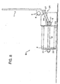
- Fig.4 is a top plan view for illustrating the overall structure of the wing door opening/closing apparatus, preferably applied to a truck shown in Fig.1, according to the first embodiment of the present invention. It should be noted that Fig.4 shows this wing door opening/closing apparatus from above, with a portion of the wall section of the cargo box frame 2 partially removed, as does Fig.11, as later explained.
- the wing door opening/closing apparatus includes a first wing door opening/closing device A, mounted between the wing door 1 and the vehicle body and accommodated within the cargo box frame 2, and a second wing door opening/closing device B mounted within a bracket 4 provided outside the cargo box frame 2.
- first wing door opening/closing device A is first explained.
- Fig.5 is a front view for illustrating the structure of the first first wing door opening/closing device A shown in Fig.4. It should be noted that Fig.5 shows this wing door opening/closing apparatus along a longitudinal direction of the vehicle, with a portion of the wall section of the cargo box frame 2 partially removed, as does Fig.6, as later explained.
- the wing door 1 has its one lateral side pivotally mounted via hinge 5 to the lateral upper side of the vehicle body (cargo box) at an upper part of the cargo box frame in the vicinity of the roof portion of the cargo box.
- a pin 6 of the hinge 5 operates as a fulcrum point of the wing door 1.
- the wing door 1 is bent at its lateral side which operates as a roof portion overlying the vehicle body or the roof portion of the cargo box, with the other bent side operating as a lateral side, not shown, covering the lateral side of the vehicle body or the cargo box.
- the first wing door opening/closing device A includes a spring 8 arranged on the top of the cargo box frame 2 and having its lateral side carried by the vehicle body or by the cargo box frame 2 for generating the force of biasing the wing door 1 into rotation, and a link mechanism 9 for transmitting the biasing force of the spring 8 to the wing door 1.
- a first link member 11 is pivotally connected to the inner lateral side of the wing door 1 via pin 10.
- a second link member 13 is pivotally connected to the first link member 11 via pin 12.
- the second link member 13 is pivotally mounted to the vehicle body via pin 14.
- a third link member 16 is pivotally connected to the second link member 13 via pin 15.
- a spring rod 18 is connected to the third link member 16 via pin 17.
- a first slider 19 is pivotally mounted by pin 17.
- a first guide member 20 (lower guide member) is secured on the vehicle body. During rotation of the wing door, the first slider 19 is guided for translation along the axis of the spring rod 18 (the axis of the spring 8) by the first guide member 20.
- An adjustment nut 21 for adjusting the initial spring length is threadedly engaged with the spring rod 18.
- a first spring retainer 22 is carried by the adjustment nut 21.
- a second spring retainer 23 is secured to the vehicle body. The aforementioned spring 8 is interposed under compression between the first spring retainer 22 and the second spring retainer.
- a stopper 24 is provided to the vehicle body for facing the end of the second link member 13 along its pivoting direction.
- Fig.7 is a front view for illustrating the structure of the second wing door opening/closing device B shown in Fig.4.
- the second wing door opening/closing device B similarly includes a spring 8 having its side carried by the vehicle body or by the cargo box frame 2 for generating the biasing force for rotating the wing door 1 and a link mechanism 26 for transmitting the biasing force of the spring 8 to the wing door 1.
- the first link member 28 is pivotally connected via pin 27 to the inner side of the wing door 1 via pin 27.
- the spring rod 18 is connected via pin 17 to the first link member 28.
- the first slider 19 is pivotally mounted on the pin 17.
- the first guide member 20 (upper guide member) is secured to the vehicle body. During rotation of the wing door, the first slider 19 is guided for translation by the first guide member 20 along the axis of the spring rod 18 (direction of the spring axis of the spring 8).
- the adjustment nut 21 for adjusting the initial spring length is threadedly engaged with the spring rod 18.
- the first spring retainer 22 is carried by the adjustment nut 21.
- the second spring retainer 23 is secured to the vehicle body.
- the aforementioned spring 8 is interposed under compression between the first spring retainer 22 and the second spring retainer.
- FIG.5 showing the closed state of the wing door 1 (first wing door opening/closing device A), to Fig.7 (second wing door opening/closing device B) and to Figs.6 and 8 showing its opened state (first wing door opening/closing device A and second wing door opening/closing device B), the operation of the above-described first wing door opening/closing device A according to the first embodiment is now explained.
- the springs 8, 8 are stretched, in the first wing door opening/closing device A and in the second wing door opening/closing device B, towards left in Figs.5 and 7, respectively. Since the direction of movement of the first slider 19 is controlled to be along the spring axis direction, by the second guide members 20, 20, the spring rods 18, 18 are also translated towards left in Fig.5, 7, respectively. As a consequence, the third link member 16 in the first wing door opening/closing device A and the first link member 28 in the second wing door opening/closing device B are swung in the clockwise direction as the overall system is translated towards left in Figs.5 and 7.
- the second link member 8 [sic. 13] in the first wing door opening/closing device A is swung in the clockwise direction in Fig.2 [sic. 5], while the first link member11 is uplifted, such that the force operating in the opening direction is transmitted to the wing door 1.
- the first link member 28 is swung in the clockwise direction in Fig.7, whereby the force operating in the opening direction is transmitted to the wing door 1.
- moment characteristics of the first wing door opening/closing device A differ from those of the second wing door opening/closing device B. That is, the first wing door opening/closing device A is arranged for generating the maximum moment at an angle of rotation larger [sic. smaller] than an angle of rotation of the wing door 1 which gives the maximum weight moment of the wing door 1, while the second wing door opening/closing device B is arranged for generating the maximum moment at an angle of rotation larger than the angle of rotation of the wing door 1 which gives the maximum weight moment of the wing door 1.
- a "curve showing the relation between the angle of rotation of the wing door 1 and the moment of the resultant force generated by the first wing door opening/closing device A and the second wing door opening/closing device B" may be made substantially coincident with a “curve showing the relation between the angle of rotation of the wing door 1 and the weight moment thereof” insofar as the magnitude of the moment and the curve shape.
- the angle between the axial direction of the spring 8 and the link mechanism 9, above all the third link member 16 connected to the spring rod 18, is closer to 180°, so that the majority of the force generated by the spring 8 operates as the force to swing (rotate) the second link member 13 from the initial stage of the range of the rotational angle of the wing door 1.
- the first wing door opening/closing device A causes a large moment to act on the wing door 1 in the initial stage of rotation of the wing door 1.
- the angle between the axial direction of the spring 8 and the link mechanism 26, above all the first link member 28 connected to the spring rod 18, is smaller [sic. larger], so that the majority of the force generated by the spring 8 operates as the force of straightening the link mechanism 26 (spring rod 18 and the link member 28) at the initial stage of the range of the rotational angle of the wing door 1.
- the second wing door opening/closing device B causes a large moment to act on the wing door 1 in the latter stage of rotation of the wing door 1.
- the wing door opening/closing device in the second embodiment of the present invention is now explained.
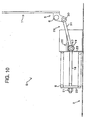
- the present second embodiment is a modification of the above-described first embodiment. Specifically, the first wing door opening/closing device A has been changed from the device shown in Fig.5 to the device shown in Fig.9.
- Fig.10 shows the operation of the first wing door opening/closing device A shown in Fig.9.
- the first wing door opening/closing device A includes a spring 8 having its one side carried by the vehicle body or by the cargo box frame 2 and adapted for generating the force of biasing the wing door 1 into rotation, and a link mechanism 29 for transmitting the biasing force of the spring 8 to the wing door 1.
- a first link member 31 is pivotally connected to the inner lateral side of the wing door 1 via pin 30.
- the spring rod 18 is connected to the first link member 31 via pin 17.
- the first slider 19 is pivotally mounted on the pin 17.
- the first guide member 20 (upper guide plate) is secured to the vehicle body. During rotation of the wing door, the first slider 19 is guided for performing a translational movement along the axis of the spring rod 18 (the axis of the spring 8) by the first guide member 20.
- An adjustment nut 21 for adjusting the initial spring length is threadedly engaged with the spring rod 18.
- a first spring retainer 22 is carried by the adjustment nut 21.
- a second spring retainer 23 is secured to the vehicle body. The aforementioned spring 8 is interposed under compression between the first spring retainer 22 and the second spring retainer.
- This first wing door opening/closing device A (see Figs.9 and 10) has moment characteristics similar to those of the first wing door opening/closing device A shown in Figs.5 and 6 (see Fig.3).
- the wing door opening/closing apparatus of the second embodiment operates similarly to the wing door opening/closing device of the first embodiment described above.
- the angle between the axial direction of the spring 8 and the link mechanism 29, above all the fist link member 31 connected to the spring rod 18, is smaller at the initial position shown in Fig.9, that is smaller than the angle between the spring rod 18 shown in Fig.7 and the first link member 28.
- the majority of the force generated by the spring 8 operates as the force of pivoting the first link member 31 from the initial stage of rotation, that is, from a beginning portion of the range of the rotational angle of the wing door 1.
- the first wing door opening/closing device A causes a large moment to operate on the wing door 1 at the initial stage of rotation of the wing door 1.
- the first sliders 19, 19 shown in Figs.8 and 9 abut against one outer lateral surfaces of the second spring retainers 23, 23, thus inhibiting further rotation of the wing door 1 to prescribe the maximum opening angle of the wing door 1.
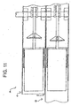
- Fig.11 is a top plan view showing the overall structure of the wing door opening/closing apparatus according to the third embodiment of the present invention.
- the wing door opening/closing apparatus includes a second wing door opening/closing device B, mounted between the wing door 1 and the vehicle body and accommodated within the cargo box frame 2, and a first wing door opening/closing device A mounted within a bracket 4 provided outside the cargo box frame 2.
- a second wing door opening/closing device B mounted between the wing door 1 and the vehicle body and accommodated within the cargo box frame 2
- a first wing door opening/closing device A mounted within a bracket 4 provided outside the cargo box frame 2.
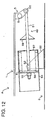
- Fig.12 is a front view for illustrating the structure of the first wing door opening/closing device A shown in Fig.11, and Fig.13 illustrates the operation for Fig. 12.
- the first wing door opening/closing device A includes a spring 8 having its one side retained by the vehicle body or the cargo box frame 2 and adapted for generating the force of biasing the wing door 1 into rotation, and a link mechanism 49 for transmitting the biasing force of the spring 8 to the wing door 1.
- a first link member 51 in the form of a straight-shaped rod is pivotally connected via pin 50 to the inner side of the wing door 1.
- a plate (bracket) 52 is secured to the vehicle body.
- a spring cover 54 is pivotally mounted via pin 53 to the plate 52.
- An adjustment nut 55 for adjusting the initial spring length is threadedly engaged with the first link member 51.
- a first spring retainer 56 is carried by the adjustment nut 55.
- a second spring retainer 57 is formed on one inner side of the spring cover 54. The aforementioned spring 8 is interposed under compression between the first spring retainer 56 and the second spring retainer 57.
- a stopper 58 is provided to the first link member 51 for facing one outer side of the spring cover 54.
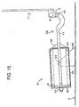
- Fig. 14 is a front view for illustrating the structure of the second wing door opening/closing device B shown in Fig.11.
- Fig.15 illustrates the operation for Fig.14.
- the second wing door opening/closing device B includes a spring 8 arranged on the top of the cargo box frame 2 and having its lateral side carried by the vehicle body or by the cargo box frame 2 for generating the force of biasing the wing door 1 into rotation, and a link mechanism 39 for transmitting the biasing force of the spring 8 to the wing door 1.
- a first link member 11 having an arcuate portion is pivotally connected via pin 40 to the inner side of the wing door 1.
- a plate (bracket) 42 is secured to the vehicle body.
- a spring cover 44 is pivotally mounted to the plate 42 via pin 43.
- An adjustment nut 45 for adjusting the initial spring length is threadedly engaged with the first link member 41.
- a first spring retainer 46 is carried by the adjustment nut 45.
- a second spring retainer 47 is formed on one inner side of the spring cover 44. The aforementioned spring 8 is interposed under compression between the first spring retainer 46 and the second spring retainer 47.
- a stopper 48 is provided to the first link member 41 for facing one outer side of the spring cover 44.
- the first wing door opening/closing device A shown in Figs.12 and 13 operates similarly to the first wing door opening/closing device A, according to the first embodiment, shown in Figs.5 and 6, while the second wing door opening/closing device B, shown in Figs.14 and 15, operates similarly to the second wing door opening/closing device B, according to the first embodiment, shown in Figs.7 and 8.
- the pin 6 is spaced apart more pronouncedly from the first ink member 51 (along the direction of the spring axis of the spring 8) in the initial position shown in Fig. 12.
- the force generated by the spring 8 be F and let the length of a plumb line drawn from pin 6 to a line segment of the force F (line segment passing through the pins 53 and 50) be L.
- L is of a longer length, at the initial position, as shown in Fig.
- the angle between the axial direction of the spring 8 and the straight line passing through the pins 40 and 6 is smaller such that the axial direction is substantially aligned with the straight line through pins 40 and 6.
- the force generated by the spring 8 is F and the length of a normal line drawn from pin 6 to a line segment of the force F (line segment passing through the pins 43 and 40) is L
- L is of a shorter length, at the initial position, as shown in Fig. 14, so that only small moment is generated in the beginning portion of the rotational extent of the wing door 1, while a larger moment is generated in the latter stage of the rotation of the wing door 1
- the stopper 48 shown in Fig.13 and the stopper shown in Fig.15 abuts against one outer lateral surfaces of the spring covers 44, 54, thus inhibiting further rotation of the wing door 1 to prescribe the maximum opening angle of the wing door 1.
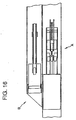
- the wing door opening/closing apparatus is a combination of the first wing door opening/closing device A shown in Fig.5 and the second wing door opening/closing device B shown in Fig. 17, in the horizontally juxtaposed state, as shown in Fig.16.
- Fig.18 illustrates the operation for the second wing door opening/closing device B shown in Fig.17.
- the above-described first embodiment is to be referenced as to the first wing door opening/closing device A and that the following explanation is centered about the second wing door opening/closing device B shown in Fig.17.
- the second wing door opening/closing device B includes a second spring 70 having its one end retained by the vehicle body or by the cargo box frame 2 for generating the force of biasing the wing door 1 into rotation, and a link mechanism 60 for transmitting the biasing force of the second spring 70 to the wing door 1.
- the link mechanism 60 includes a second-1 link member 63 pivotally and slidably connected to the inner side of the wing door 1 and pivotally mounted to the vehicle body.
- a second spring rod 66 is connected via pin 65 to the second-1 link member 63.
- a slider 62 On a side where the second-1 link member 63 is connected to the inner side of the wing door 1 is mounted a slider 62 via pin 61.
- a first spring retainer 69 is carried at an end of the second spring rod 66 via adjustment nut.
- a spring cover 68 is pivotally mounted via pin 67 to the vehicle body 2. The inner surface of the spring cover 68 operates as the second spring retainer.
- a second spring 70 is mounted under compression between the first spring retainer 69 and the inner surface of the spring cover 68.
- the present fifth embodiment is a modification of the fourth embodiment and is a combination of the first wing door opening/closing device A shown in Fig.5 and the second wing door opening/closing device B shown in Fig.19, in the horizontally juxtaposed state, as shown in Fig.16.
- Fig.20 illustrates the operation for the second wing door opening/closing device B shown in Fig.19.
- first and fourth embodiments are to be referenced as to the first wing door opening/closing device A and as to the basic structure of the second wing door opening/closing device B, respectively, and that the following explanation is to be centered about the difference between the second wing door opening/closing device B shown in Fig.17 and the second wing door opening/closing device B of the present embodiment.
- the wing door opening/closing apparatus of the present embodiment includes a stopper 83 for halting the operation of the second wing door opening/closing device B of the plural wing door opening/closing devices A and B, at a preset position, during opening the wing door.
- the wing door opening/closing device B on which acts the stopper 83, includes a second spring 70 (see Fig.17), for generating the driving force (swinging up force) for opening/closing the wing door 1, and a link mechanism 60, pivotally mounted to the vehicle body 2, and having its one side slidably and pivotally connected to the inner side of the wing door 1 and having its opposite side connected to the second spring 70 for transmitting the driving force of the second spring 70 to the wing door 1.
- the link mechanism 60 includes the second-1 link member 63.
- a slider 62 is mounted via pin 61 to one end of the second-1 link member 63, the other end of which mounts a spring rod 66 through pin 65.
- the stopper 83 is adapted for abutting against the link mechanism 60-or the second-1 link member 63 at a preset angle of rotation of the wing door 1 to halt further swinging of the link mechanism 60 or the second-1 link member 63.
- the portion of the link mechanism 60 having sliding contact with the inner side of the wing door 1, that is the slider 62, is spaced apart by L from the slide contact surface with the wing door 1 when the stopper 83 is in operation and the operation of the wing door opening/closing device B has ceased.
- the driving force generated by the second wing door opening/closing device B ceases to act on the wing door 1.
- the driving force of the plural wing door opening/closing devices A and B act on the wing door 1 and, as from the preset angle of rotation (latter half rotation) of the wing door 1, the driving force of the sole wing door opening/closing device A acts on the wing door 1.
- the wing door opening/closing apparatus comprising the combination of the first wing door opening/closing device A and the second wing door opening/closing device B having respective different operating ranges, an optimum wing door driving moment, that is an optimum swinging-up force, may be developed depending on the moment characteristics of the wing door 1.
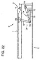
- the wing door opening/closing apparatus is a combination of the first wing door opening/closing device A shown in Fig.5 and the second wing door opening/closing device C shown in Fig.22, in the horizontally juxtaposed state, as shown in Fig.21.
- Fig.23 illustrates the operation for the first wing door opening/closing device B shown in Fig.22.
- the above-described first embodiment is to be referenced as to the first wing door opening/closing device A and that the following explanation is centered about the second wing door opening/closing device C shown in Fig.22.
- the second wing door opening/closing device C includes a second-1 link member 73, pivotally connected to the inner side of the wing door 1, a second spring member 74, connected via pin 78 to the second-1 link membèr 73, and a second-2 link member 75, pivotally mounted via pin 77 to the vehicle body 2 and connected via pin 78 to a junction point between the second-1 link member 73 and the second spring rod 74. That is, the second-1 link member 73, second spring rod 74 and the second-2 link member 75 are interconnected by the same pin 78.
- the link mechanism 71 is made up by the second-1 link member 73, second spring rod 74 and the second-2 link member 75.
- the second spring member 74 includes a casing 74a, connected via pin 76 to the vehicle body 2, a rod 74b enclosed in the casing 74a and connected via pin 78 to the second-1 link member 73 and a second spring 74c interposed between the casing 74a and the rod 74b.
- the second spring member 74 is pivoted and simultaneously contracted, during opening the wing door 1, with swinging of the second-1 link member, as the second spring member 74 is guided by the second-2 link member 75.
- the second spring 74c so far compressed by this contraction, gradually expands to develop the driving force of swinging-up the wing door 1. Meanwhile, the operation during closing the wing door 1 is the reverse of the above-described operation.
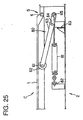
- the wing door opening/closing apparatus according to a seventh embodiment of the present invention is now explained.
- the wing door opening/closing apparatus according to the seventh embodiment is a combination of the first wing door opening/closing device A shown in Fig.5 and a second wing door opening/closing device C shown in Fig.25, in the horizontally juxtaposed state, as in the case shown in Fig.21.
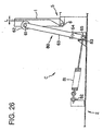
- Fig.26 illustrates the operation for the first wing door opening/closing device C shown in Fig.26.
- the above-described first embodiment is to be referenced as to the first wing door opening/closing device A and that the following explanation is centered about the second wing door opening/closing device C shown in Fig.25.
- the wing door opening/closing apparatus of the present embodiment includes a stopper 83 for halting the operation of the second wing door opening/closing device C of the plural wing door opening/closing devices A and C, at a preset position, when opening the wing door.
- the wing door opening/closing device C on which acts the stopper 83, includes a second spring member (tension spring) 81 for generating the driving force for opening/closing the wing door 1, and a link mechanism 80, pivotally mounted to the vehicle body 2, and having its one side slidably and pivotally connected (abutted) to the inner side of the wing door 1 and having its opposite side connected (linked) to the second spring member 81 for transmitting the driving force of the second spring member 81 to the wing door 1.
- tension spring tension spring
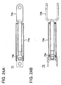
- Figs.27A and 27B are detailed views showing the spring member shown in Fig.25.
- the second spring member 81 includes a second spring (tension spring) 81a, a first connecting portion 81b for retaining one end of the second spring 81a on a pin 65 on the second-1 link member 63, and a second connecting portion 81c for pivotally mounting the opposite end of the spring 81a to the vehicle body 2.
- the link mechanism 80 includes a second-1 link member 63, to one end of which is mounted the slider 62 via pin 61 and to the opposite end of which a second spring member 81 is mounted via pin 65.
- the stopper 83 is mounted to the vehicle body 2 and abuts against the link mechanism 60 or the second-1 link member 63 at a preset rotational angle of the wing door 1 to halt further pivoting of the second-1 link member 63.
- the portion of the link mechanism 60 having sliding contact with the inner side of the wing door 1, that is the slider 60, is spaced apart at L (see Fig.26) from the slide contact surface with the wing door 1 when the stopper 83 is in operation and the operation of the wing door opening/closing device B has ceased.
- the portion of the link mechanism 60 having sliding contact with the inner side of the wing door 1, that is the slider 62, is spaced apart by L from the slide contact surface with the wing door 1 when the stopper 83 is in operation and the operation of the wing door opening/closing device C has ceased.
- the driving force generated by the second wing door opening/closing device C ceases to act on the wing door 1.
- the driving force of the plural wing door opening/closing devices A and B acts on the wing door 1 and, as from the preset angle of rotation (latter half rotation) of the wing door 1, the driving force of the sole wing door opening/closing device A acts on the wing door 1.
- the wing door opening/closing apparatus comprising the combination of the first wing door opening/closing device A and the second wing door opening/closing device B having respective different operating ranges, an optimum wing door driving moment, that is an optimum swinging-up force, may be developed depending on the moment characteristics of the wing door 1.
- the wing door opening/closing apparatus is a combination of the first wing door opening/closing device A shown in Fig.5 and a second wing door opening/closing device D shown in Fig.17, in the horizontally juxtaposed state, as shown in Fig.21.
- Figs.29A and 29B are detailed views of a torsion spring 90 shown in Fig.28. It should be noted that the above-described first embodiment is to be referenced as to the first wing door opening/closing device A and that the following explanation is centered about the second wing door opening/closing device D shown in Fig.28.
- the second wing door opening/closing device D of the present embodiment includes a wing door 1, pivotally mounted to the vehicle body via pin 6 of hinge 5, a first bracket 1b mounted to the inner side of the wing door 1, a second bracket 3a mounted to the lateral surface of a center beam 3 secured to the vehicle body 2, and a torsion spring 90 mounted under compression between the first bracket 1b and the second bracket 3a (between the wing door 1 and the vehicle body 2), as shown in Fig.29A.
- the second wing door opening/closing device D applies a swinging-up force to the wing door 1 during the initial stage of the opening of the wing door 1. If, at a preset rotational angle of the wing door 1, the torsion coil spring 90 reaches the state shown in Fig.29B (i.e., a larger stroke), the second wing door opening/closing device D ceases to exert the swinging-up force to the wing door 1. Subsequently, the wing door 1 continues to be swung by the first wing door opening/closing device A.
- the present embodiment of the wing door opening/closing apparatus a larger swinging up force may be developed during the early stage of the opening of the wing door 1.
- the torsion spring 90 of the present embodiment may be replaced by springs of other types, such as rod-shaped torsion bar.
- the wing door opening/closing apparatus according to a ninth embodiment of the present invention is now explained.
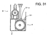
- the wing door opening/closing apparatus according to this ninth embodiment comprises a first wing door opening/closing device A basically having the structure shown in Fig.5 and a second wing door opening/closing device B basically having the structure shown in Fig.19, with the wing door opening/closing devices A and B being vertically juxtaposed to each other, as shown in Figs.30 to 32.
- first and fifth embodiments should be referenced as to the basic structures of the first wing door opening/closing device A and the second wing door opening/closing device B, respectively, and the following description is centered about the point of difference of the present embodiment from the fifth embodiment described above.
- the above-described fifth embodiment of the wing door opening/closing apparatus is a combination of the first wing door opening/closing device A shown in Fig.5 and the second wing door opening/closing device B shown in Fig.19, in the horizontally juxtaposed or side-by-side state, as shown in Fig.16.
- the first wing door opening/closing device A and the second wing door opening/closing device B are juxtaposed or arranged side-by-side along the vertical direction, as shown in Figs.30 to 32.
- the hinge pins 5 and 6 of the wing door 1 are provided at the positions higher than those shown in Figs.5 and 6.
- a mounting plate 91 secured to the vehicle body 2.
- a cut-out 91a for allowing the swinging of the first-1 link member 11 provided to the first wing door opening/closing device A.
- the length of the first-1 link member 11 is designed to be longer than that of the first link member 11 of Fig.5 for arranging the second wing door opening/closing device B above the first wing door opening/closing device A.
- the length of the second-1 link member 63 provided to the second wing door opening/closing device B is also designed to be longer than that of the second-1 link member 63 shown in Fig. 19.
- the wing door opening/closing apparatus of the present embodiment operates similarly to the wing door opening/closing apparatus of the above-described fifth embodiment. Moreover, in the present embodiment of the wing door opening/closing apparatus, in which the plural wing door opening/closing devices A, B are arranged side-by-side along the vertical direction, it is possible to provide a larger capacity for the cargo box.
Landscapes
- Engineering & Computer Science (AREA)
- Mechanical Engineering (AREA)
- Closing And Opening Devices For Wings, And Checks For Wings (AREA)
- Power-Operated Mechanisms For Wings (AREA)
Abstract
Description
- This invention relates to a wing door opening/closing apparatus and, more particularly, to a wing door opening/closing apparatus for a truck or the like.
- Up to now, a hydraulic cylinder or a motor has been used as a driving apparatus for opening/closing a wing door.
- However, if a hydraulic cylinder or a motor is used as a driving apparatus for opening/closing a wing door, in general, is used, piping, wiring or power supply is needed for driving the hydraulic cylinder or motor. This poses a problem that since the mechanism for opening/closing the wing door becomes bulky in size, extremely labor-consuming maintenance operations are needed, and that, should the driving apparatus be in disorder, extremely labor-consuming repair operations are also needed.
- It is an object of the present invention to provide an apparatus for opening/closing a wing door, which makes use of a spring and a link mechanism, which is simplified in structure and which scarcely needs any maintenance operations. It is another object of the present invention to provide an apparatus for opening/closing a wing door, which is able to apply a necessary and sufficient moment to the wing door door depending on the angle of rotation of the wing door.
- For accomplishing the above objects, the present invention provides an apparatus for opening/closing a wing door which is constituted by combining a plurality of wing door opening/closing devices having respective different moment characteristics representing the relation between the angle of rotation of the wing door and a moment generated by the wing door opening/closing devices.
- In another aspect, the present invention provides a wing door opening/closing apparatus for swinging up a wing door pivotally mounted to a cargo box of a vehicle body of a truck or the like in the vicinity of a roof portion of the cargo box so that the wing door overlies the roof portion and lateral sides of the cargo box, wherein the wing door opening/closing apparatus is formed by combining a plurality of wing door opening/closing devices having respective different moment characteristics representing the relationship between a moment caused by the weight of the wing door being rotated and moments generated by the respective wing door opening/closing devices. At least one of the wing door opening/closing devices includes a spring for generating the biasing force for swinging up the wing door and a link mechanism for transmitting the biasing force of the spring to the wing door.
- In still another aspect, the present invention provides a wing door opening/closing apparatus for swinging up a wing door pivotally mounted to a cargo box of a vehicle body of a truck or the like in the vicinity of a roof portion of the cargo box so that the wing door overlies the roof portion and lateral sides of the cargo box, wherein the wing door opening/closing apparatus is made up by a plurality of wing door opening/closing devices, the disparity of a moment produced by one of the wing door opening/closing devices with respect to a moment caused by the weight of the wing door being rotated is compensated by a moment generated by the remaining one of the wing door opening/closing devices and wherein at least one of the wing door opening/closing devices includes a spring for generating a biasing force for swinging up the wing door and a link mechanism for transmitting the biasing force of the spring to the wing door.
- According to the present invention, such a wing door opening/closing apparatus may be provided which is simplified in structure by making use of a spring and a link mechanism so that maintenance is substantially not necessary. Moreover, such a wing door opening/closing apparatus may be provided in which, by combining plural wing door opening/closing devices having respective different moment characteristics, the sum moment substantially balanced with respect to the weight moment of the wing door at an optional rotational angle of the wing door may be output despite the simplified structure of the respective wing door opening/closing devices.
- According to the present invention, such a wing door opening/closing apparatus may be provided which is substantially maintenance-free and has a simplified structure comprised of a spring and a link mechanism and also such a wing door opening/closing apparatus which is able to apply sufficient and necessary moment to the wing door depending on the angle of rotation of the wing door.
- In addition, at least one of plural wing door opening/closing devices, making up the wing door opening/closing apparatus, has a link mechanism and a spring, so that the biasing force of the spring may be boosted and transmitted to the wing door to develop a large moment for swinging-up the wing door.
-
- Fig.1 is a perspective view showing a truck to which the wing door opening/closing apparatus of the present invention is applied.
- Fig.2 illustrates the structure of a cargo box frame provided to the truck shown in Fig.1.
- Fig.3 is a graph for illustrating moment characteristics of the wing door opening/closing apparatus according to an embodiment of the present invention.
- Fig.4 is a plan view of a wing door opening/closing apparatus according to an embodiment of the present invention.
- Fig.5 is a front view of a first wing door opening/closing device A contained in the wing door opening/closing apparatus shown in Fig.4.
- Fig.6 shows the operation of the first wing door opening/closing device A shown in Fig.5.
- Fig.7 is a front view of a second wing door opening/closing device B contained in the wing door opening/closing apparatus shown in Fig.4.
- Fig.8 shows the operation of the second wing door opening/closing device B shown in Fig.7.
- Fig.9 is a front view of a first wing door opening/closing device A contained in the wing door opening/closing apparatus according to a second embodiment of the present invention.
- Fig. 10 shows the operation of the first wing door opening/closing device shown in Fig.9.
- Fig.11 is a plan view of a wing door opening/closing apparatus according to a third embodiment of the present invention.
- Fig. 12 is a front view of the first wing door opening/closing device A contained in the wing door opening/closing apparatus shown in Fig.11.
- Fig.13 shows the operation of the first wing door opening/closing device A shown in Fig. 11.
- Fig. 14 is a front view of the first wing door opening/closing device A contained in the wing door opening/closing apparatus shown in Fig.11.
- Fig. 15 shows the operation of the first wing door opening/closing device B shown in Fig.14.
- Fig.16 is a plan view of the second wing door opening/closing device according to a fourth embodiment of the present invention.
- Fig.17 is a front view of the second wing door opening/closing device B contained in the wing door opening/closing apparatus shown in Fig. 16.
- Fig.18 shows the operation of the second wing door opening/closing device B shown in Fig.17.
- Fig.19 is a front view of the second wing door opening/closing device B contained in the wing door opening/closing apparatus according to a fifth embodiment of the present invention..
- Fig.20 shows the operation of the second wing door opening/closing device B shown in Fig.19.
- Fig.21 is a plan view of a wing door opening/closing apparatus according to a sixth embodiment of the present invention.
- Fig.22 is a front view of a second wing door opening/closing device C contained in the wing door opening/closing apparatus shown in Fig.21.
- Fig.23 shows the operation of the second wing door opening/closing device C shown in Fig.22.
- Figs.24(A) and 24(B) show details of a second spring member shown in Fig.21, with Figs.24(A), 24(B) being a front view and a plan view, respectively.
- Fig.25 is a front view of the second wing door opening/closing device C contained in the wing door opening/closing apparatus according to a seventh embodiment of the present invention.
- Fig.26 shows the operation of the second wing door opening/closing device C shown in Fig.22.
- Figs.27(A) and 27(B) show details of a second spring member shown in Fig.21, with Figs.24(A), 24(B) being a front view and a plan view, respectively.
- Fig.28 is a front view of the second wing door opening/closing device D contained in the wing door opening/closing apparatus according to a seventh embodiment of the present invention.
- Figs.29(A) and 29(B) show details of a torsion coil spring shown in Fig.28, with Figs.29(A), 29(B) showing the state of initial compression and interposition and the state of operation termination, respectively.
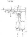
- Fig.30 is a front view of a wing door opening/closing apparatus according to a ninth embodiment of the present invention.
- Fig.31 is a side view of the wing door opening/closing apparatus according to the ninth embodiment of the present invention. Fig.32 shows the operation of the wing door opening/closing apparatus shown in Fig.30.
-
-
- 1
- wing
- 1b
- first bracket
- 2
- cargo box frame
- 3
- beam, center beam
- 3a
- second bracket
- 4
- bracket (mounting bracket for first or second wing opening/closing devce
- 5
- hinge (wing hinge)
- 6
- pin (pin for wing hinge)
- 8
- spring
- 9
- link mechanism
- 10
- pin
- 11
- first link member
- 12
- pin
- 13
- second link member
- 14
- pin
- 15
- pin
- 16
- third link member
- 17
- pin
- 18
- spring rod
- 19
- third slider
- 20
- first guide member
- 21
- adjustment nut
- 22
- first spring retainer
- 23
- second spring retainer
- 24
- stopper
- 26
- link mechanism
- 27
- pin
- 28
- first link member
- 29
- link mechanism
- 30
- pin
- 31
- first link member
- 39.
- link mechanism
- 40
- pin
- 41
- first link member
- 42
- plate (fixed plate)
- 43
- pin (fulcrum point for spring cover 44)
- 44
- spring cover
- 45
- adjustment nut
- 46
- first spring retainer
- 47
- second spring retainer
- 48
- stopper
- 49
- link mechanism
- 50
- pin
- 51
- first link member
- 52
- plate (fixed plate)
- 53
- pin (fulcrum point for spring cover 54)
- 54
- spring cover
- 55
- adjustment nut
- 56
- first spring retainer
- 57
- second spring retainer
- 58
- stopper
- 60
- link mechanism
- 61
- pin
- 62
- slider
- 63
- second-1 link member
- 65
- pin
- 66
- spring rod, second spring rod
- 67
- pin
- 68
- spring cover
- 69
- first spring retainer
- 70
- spring, second spring
- 71
- link mechanism
- 72
- pin
- 73
- second-1 link member
- 74
- second spring member
- 74a
- casing
- 74b
- rod
- 74c
- second spring
- 75
- second-2 link member
- 76
- pin
- 78
- pin
- 80
- link mechanism
- 81
- second spring member (tension spring)
- 81a
- second spring (tension spring)
- 83
- stopper
- 81
- second spring member (tension spring)
- 81a
- first spring (tension spring)
- 81b
- second spring (torsion spring)
- 83
- stopper
- 81
- spring member
- 81b
- first connecting portion
- 81c
- second connecting portion
- 83
- stopper
- 90
- torsion spring
- 91
- mounting plate
- 91a
- cut-out
- A
- first wing opening/closing device
- B
- second wing opening/closing device
- C
- second wing opening/closing device
- D
- second wing opening/closing device
- Now, preferred modes embodying the present invention will be illustrated.
- In the preferred embodiment of the present invention, one of the plural wing door opening/closing devices having respective different moment characteristics is accommodated in a cargo box frame when the wing door is closed, with the other being mounted to outside of the cargo box frame in a side-by-side relation to the first stated device along the fore-and-aft direction of the vehicle body.
- For example, a first wing door opening/closing device A is accommodated in the inside of a cargo box frame ("torii") 2, while a second wing door opening/closing device B is mounted on the outer side of the
cargo box frame 2. This structure may be reversed. In addition, the wing door opening/closing device mounted on the outer side of the cargo box frame may be directly mounted to the cargo box frame or to the vehicle body, or may also be mounted indirectly through e.g., a bracket to the cargo box frame or to the vehicle body. - Still alternatively, plural wing door opening/closing devices may be arranged side-by-side within the cargo box frame.
- In another preferred embodiment of the present invention, plural wing door opening/closing devices may be mounted side by side or in adjacency to one another in the vertical direction, as shown in Figs.30 to 32. In this embodiment, a larger space may be secured within the cargo box.
- In a wing door opening/closing apparatus according to a preferred embodiment of the present invention, the plural wing door opening/closing devices having the respective different moment characteristics include a first wing door opening/closing device generating a maximum moment at an angle of rotation of the wing door larger than an angle of rotation thereof for which the weight moment of the wing door is maximum, and a second wing door opening/closing device generating a maximum moment at an angle of rotation of the wing door smaller than the angle of rotation thereof for which the weight moment of the wing door is maximum.
- Stated differently, the wing door opening/closing apparatus is made up by plural wing door opening/closing devices having respective different moment characteristics representing the relation between the moment generated by the weight of the rotating wing door and the moment generated by the wing door opening/closing device.
- For example, referring to Fig.3, the first wing door opening/closing device A has moment characteristics shown by a curve A, whilst a second wing door opening/closing device B has moment characteristics shown by curve B, with the sum of the moment characteristics, indicated by a curve (A+B), which curve (A+B) is substantially similar to and approximately equal in the moment magnitude to a curve representing weight moment characteristics of a wing door.
- As a consequence, the disparity between the moment generated by the wing door opening/closing device A is compensated by the moment generated by the other wing door opening/closing device B.
- Moreover, by combining one wing door opening/closing device, operating throughout the entire range of rotation of the wing door, with another wing door opening/closing device, the range of the operation of which is limited, it is possible to elevate the swinging-up power acting on the wing door in the former half of the rotational range of the wing door. Alternatively, it is possible to elevate the swinging-up power acting on the wing door in the latter half or in an intermediate area of the rotational range of the wing door.
- The wing door opening/closing apparatus according to a preferred embodiment of the present invention includes a stopper in which, on opening the wing door, at least one member of the link mechanism abuts against a member secured or fixed to the vehicle body, at a preset wing door opening angle, to inhibit the operation of the link mechanism thereby to control the maximum opening degree of the wing door.
- In the first and second wing door opening/closing devices of the wing door opening/closing apparatus, according to a preferred embodiment of the present invention, the link mechanism is made up by one or plural link members, interconnected by a pin, while there is provided a guide member, such as slider or guide roll, for guiding the plural components or the pin interconnecting the respective components.
- Preferably, the guide member is a component which is disposed at a fixed position to the vehicle body and which extends in a basically parallel direction to the spring axis direction of the spring (for example, a component having a guide surface or guide rail). On a point of interconnection (linking point or pivotal point) of the plural link members, a first slider or roll (such as a slider) is mounted for sliding on the guide member when the wing door is opened or closed. The guide member resistively supports the first slider as the guide member has a sliding contact with the first slider during wing door opening/closure to prohibit swinging of the spring rod.
- Also preferably, the guide member is a second slider or roll pivotally mounted to the vehicle body. This second slider resistively supports the spring rod, as it has sliding contact with the spring rod, so that the spring rod is not swung during the opening/closure of the wing door.
- Still alternatively, a friction member is provided at a site of connection of the link member to the wing door to cause the link member to have sliding contact with the wing door through the friction member.
- In another preferred embodiment of the present invention, shown in Figs.5 and 7, the wing door opening/closing apparatus is made up by a first wing door opening/closing device A and a second wing door opening/closing device B. The first wing door opening/closing device A includes a first-1
link member 11, pivotally connected to the inner surface of thewing door 1, a first-2link member 13, pivotally mounted to thevehicle body 2 and pivotally connected to the first-1link member 11, a first-3link member 16, pivotally connected to the first-2link member 13, a first-1spring rod 18, connected to the first-3link member 16, a first-1guide member 20 for translating a junction point between the first-3link member 16 and thespring rod 18 and afirst spring 8 interposed between thevehicle body 2 and thespring rod 18. On the other hand, the second wing door opening/closing device B includes a second-1link member 28, pivotally connected to the inner surface of thewing door 1, asecond spring rod 18 pivotally connected to the second-1link member 28, asecond spring 8 interposed between the vehicle body and the second spring rod, and a second-1guide member 20 for translating a junction point between the second-1link member 28 and thesecond spring rod 18. - In a preferred embodiment of the present invention, shown in Figs.7 and 9, the wing door opening/closing apparatus of the present invention is made up by a first wing door opening/closing device A and a second wing door opening/closing device B. Each of the first and second wing door opening/closing devices A, B includes
first link members spring rod 18 connected to thefirst link members spring 8 interposed between the vehicle body and thespring rod 18, and aguide member 20 for translating a junction point between thefirst link members spring rod 18. In the closed position of the wing door, an angle defined between the direction of the spring axis of thespring 8 and thefirst link members - In another preferred embodiment of the present invention, shown in Figs.12 and 14, the wing door opening/closing apparatus according to the present invention is made up by the first wing door opening/closing device A and the second wing door opening/closing device B. Each of the first and second wing door opening/closing devices A and B is pivotally connected to the inner surface of the wing door, and includes
first link members spring 8 interposed between the vehicle body and thefirst link members wing door 1, the arm of the moment drawn down vertically from a fulcrum point (pin) 6 of thewing door 1 to a line segment interconnecting a point of connection of thespring 8 to thefirst link members first link members wing door 1 is set so as to be longer in the first wing door opening/closing , device than in the second wing door opening/closing device. - In another preferred embodiment of the present invention, shown in Figs.5, 17 and 25, the wing door opening/closing apparatus of the present invention is made up by the first wing door opening/closing device A and the second wing door opening/closing device B. The first wing door opening/closing device A includes a first-1
link member 11, pivotally connected to the inner surface of thewing door 1, a first-2link member 13, pivotally mounted to the vehicle body and pivotally connected to the first·1link member 11, a first-3link member 16, pivotally connected to the first-2link member 13, a first-1spring rod 18, connected to the first-3link member 16, a first-1guide member 20 for translating a junction point between the first-3link member 16 and thespring rod 18, and afirst spring 8 interposed between thevehicle body 2 and thespring rod 18. On the other hand, the second wing door opening/closing device B includes a second-1link member 63, pivotally slidably connected to the inner side of the wing door and pivotally mounted to the vehicle body, asecond spring rod 66, connected to the second-1link member 63, andsecond springs link member 63, with or without interposition of thesecond spring rod 66. - In another preferred embodiment of the present invention, shown in Fig.5 and 21, the wing door opening/closing apparatus of the present invention is made up by a first wing door opening/closing device A and a second wing door opening/closing device C. The first wing door opening/closing device A includes a first-1
link member 11, pivotally connected to the inner surface of thewing door 1, a first-2link member 13, pivotally mounted to thevehicle body 2 and pivotally connected to the first-1link member 11, a first-3link member 16, pivotally connected to the first-2link member 13, a first-1spring rod 18, connected to the first-3link member 16, a first-1guide member 20 for translating a junction point between the first-3link member 16 and thespring rod 18 and afirst spring 8 interposed between thevehicle body 2 and thespring rod 18. On the other hand, the second wing door opening/closing device C includes a second-1link member 73, pivotally connected to the inner surface of thewing door 1, asecond spring member 74 connected to the second-1link member 73, asecond spring 74a (see Fig.24) interposed between the vehicle body and thesecond spring member 74 for pivoting relative to the vehicle body and a second-2link member 75 pivotally mounted to the vehicle body and connected to a junction point between the second·1link member 73 and thesecond spring member 74. - In a preferred embodiment of the present invention, the wing door opening/closing apparatus has first and second wing door opening/closing devices having different operating ranges.
- In a preferred embodiment of the present invention, there is provided a
stopper 83 for halting the operation of at least one of the plural wing door opening/closing devices at the time of opening the wing door. With this stopper, it is possible to limit one of the plural wing door opening/closing devices to provide for different operating ranges of the plural wing door opening/closing devices. - In a preferred embodiment of the present invention, shown in Fig. 19, the wing door opening/closing device B, on which acts the
stopper 83, includes a spring 70 (see Fig.17) for generating the driving force for opening/closing thewing door 1, and alink mechanism 60, pivotally connected to the vehicle body. Thelink mechanism 60 has its one end pivotally slidably connected to the inner side of thewing door 1, while having its other end connected to thespring 70, to transmit the driving force of the spring to thewing door 1. The portion of the link mechanism having a sliding contact with the inner surface of the wing door is separated away from the slide contact surface of thewing door 1, as indicated at L in Fig.20, when thestopper 83 is actuated to halt the operation of the wing door opening/closing device on which acts the stopper (see Fig.20).. - In a preferred embodiment of the present invention, at least one of the plural wing door opening/closing devices includes a torsion spring interposed between the inner surface of the wing door and the vehicle body. By selecting the stroke of this torsion spring to be smaller and by selecting that of the other wing door opening/closing device to be longer, it is possible to increase the swinging-up force acting on the
wing door 1 in the former half of the wing door rotation in opening the wing door. - In a preferred embodiment of the present invention, in at least one and preferably in either of the wing door opening/closing devices, there are provided a spring and a link mechanism for boosting the spring force of the spring to develop a larger swinging-up power. That is, with the wing door opening/closing apparatus according to the present invention, having the link mechanism, it is possible not only to hold the wing door at a preset angle of rotation, but also to hoist the wing door without using manual operations.
- In another preferred embodiment of the present invention, all of the plural wing door opening/closing devices are arranged in the vicinity or on top of the roof portion of the vehicle (see Figs.2, 4 and 31).
- The wing door opening/closing apparatus according to the present invention may be used with advantage as a device for closing at least a portion of the lateral side and at least a portion of the roof portion of the vehicle body of, for example, a truck. In addition, the wing door opening/closing apparatus according to the present invention may also be used as a device for opening/closing the wing door provided to a vehicle other than a truck.
- The wing door opening/closing apparatus according to the present invention may be used with advantage as a device for opening/closing a wing door pivotally mounted to the vehicle body of, for example, a truck, in the vicinity of the roof portion of a cargo box, for covering the roof portion and lateral sides of the cargo box, in particular as a device for swinging-up and opening the wing door. When the wing door opening/closing apparatus of the present invention is applied to a vehicle, such as a truck, having the cargo box, this wing door opening/closing apparatus can be housed within the cargo box frame (the frame portion secured to or formed as one with the vehicle body).
- For further clarifying the above-described preferred embodiment of the present invention, reference is had to the accompanying drawings for explanation of the certain preferred embodiments of the present invention.
- A wing door opening/closing apparatus according to a first embodiment of the present invention is now explained. Fig.4 is a top plan view for illustrating the overall structure of the wing door opening/closing apparatus, preferably applied to a truck shown in Fig.1, according to the first embodiment of the present invention. It should be noted that Fig.4 shows this wing door opening/closing apparatus from above, with a portion of the wall section of the
cargo box frame 2 partially removed, as does Fig.11, as later explained. - Referring to Fig.4, the wing door opening/closing apparatus according to the first embodiment of the present invention includes a first wing door opening/closing device A, mounted between the
wing door 1 and the vehicle body and accommodated within thecargo box frame 2, and a second wing door opening/closing device B mounted within abracket 4 provided outside thecargo box frame 2. Of these, the first wing door opening/closing device A is first explained. - Fig.5 is a front view for illustrating the structure of the first first wing door opening/closing device A shown in Fig.4. It should be noted that Fig.5 shows this wing door opening/closing apparatus along a longitudinal direction of the vehicle, with a portion of the wall section of the
cargo box frame 2 partially removed, as does Fig.6, as later explained. - Referring to Fig.5, the
wing door 1 has its one lateral side pivotally mounted viahinge 5 to the lateral upper side of the vehicle body (cargo box) at an upper part of the cargo box frame in the vicinity of the roof portion of the cargo box. Apin 6 of thehinge 5 operates as a fulcrum point of thewing door 1. Thewing door 1 is bent at its lateral side which operates as a roof portion overlying the vehicle body or the roof portion of the cargo box, with the other bent side operating as a lateral side, not shown, covering the lateral side of the vehicle body or the cargo box. - The first wing door opening/closing device A includes a
spring 8 arranged on the top of thecargo box frame 2 and having its lateral side carried by the vehicle body or by thecargo box frame 2 for generating the force of biasing thewing door 1 into rotation, and alink mechanism 9 for transmitting the biasing force of thespring 8 to thewing door 1. - In the
link mechanism 9, afirst link member 11 is pivotally connected to the inner lateral side of thewing door 1 viapin 10. Asecond link member 13 is pivotally connected to thefirst link member 11 viapin 12. Thesecond link member 13 is pivotally mounted to the vehicle body viapin 14. Athird link member 16 is pivotally connected to thesecond link member 13 viapin 15. Aspring rod 18 is connected to thethird link member 16 viapin 17. Afirst slider 19 is pivotally mounted bypin 17. a first guide member 20 (lower guide member) is secured on the vehicle body. During rotation of the wing door, thefirst slider 19 is guided for translation along the axis of the spring rod 18 (the axis of the spring 8) by thefirst guide member 20. - An
adjustment nut 21 for adjusting the initial spring length is threadedly engaged with thespring rod 18. Afirst spring retainer 22 is carried by theadjustment nut 21. Asecond spring retainer 23 is secured to the vehicle body. Theaforementioned spring 8 is interposed under compression between thefirst spring retainer 22 and the second spring retainer. - A
stopper 24 is provided to the vehicle body for facing the end of thesecond link member 13 along its pivoting direction. - Fig.7 is a front view for illustrating the structure of the second wing door opening/closing device B shown in Fig.4. Referring to Fig.7, the second wing door opening/closing device B similarly includes a
spring 8 having its side carried by the vehicle body or by thecargo box frame 2 for generating the biasing force for rotating thewing door 1 and alink mechanism 26 for transmitting the biasing force of thespring 8 to thewing door 1. - In the
link mechanism 26, thefirst link member 28 is pivotally connected viapin 27 to the inner side of thewing door 1 viapin 27. Thespring rod 18 is connected viapin 17 to thefirst link member 28. Thefirst slider 19 is pivotally mounted on thepin 17. The first guide member 20 (upper guide member) is secured to the vehicle body. During rotation of the wing door, thefirst slider 19 is guided for translation by thefirst guide member 20 along the axis of the spring rod 18 (direction of the spring axis of the spring 8). - The
adjustment nut 21 for adjusting the initial spring length is threadedly engaged with thespring rod 18. Thefirst spring retainer 22 is carried by theadjustment nut 21. Thesecond spring retainer 23 is secured to the vehicle body. Theaforementioned spring 8 is interposed under compression between thefirst spring retainer 22 and the second spring retainer. - Referring to Fig.5, showing the closed state of the wing door 1 (first wing door opening/closing device A), to Fig.7 (second wing door opening/closing device B) and to Figs.6 and 8 showing its opened state (first wing door opening/closing device A and second wing door opening/closing device B), the operation of the above-described first wing door opening/closing device A according to the first embodiment is now explained.
- When the operator unlocks the
wing door 1, to cause rotation of thewing door 1, thesprings first slider 19 is controlled to be along the spring axis direction, by thesecond guide members spring rods third link member 16 in the first wing door opening/closing device A and thefirst link member 28 in the second wing door opening/closing device B are swung in the clockwise direction as the overall system is translated towards left in Figs.5 and 7. - In this manner, the second link member 8 [sic. 13] in the first wing door opening/closing device A is swung in the clockwise direction in Fig.2 [sic. 5], while the first link member11 is uplifted, such that the force operating in the opening direction is transmitted to the
wing door 1. In the second wing door opening/closing device B, thefirst link member 28 is swung in the clockwise direction in Fig.7, whereby the force operating in the opening direction is transmitted to thewing door 1. By the resultant force of moment generated by the first wing door opening/closing device A and by the second wing door opening/closing device B, thewing door 1 is rotated in its opening direction. - It should be noted that moment characteristics of the first wing door opening/closing device A differ from those of the second wing door opening/closing device B. That is, the first wing door opening/closing device A is arranged for generating the maximum moment at an angle of rotation larger [sic. smaller] than an angle of rotation of the
wing door 1 which gives the maximum weight moment of thewing door 1, while the second wing door opening/closing device B is arranged for generating the maximum moment at an angle of rotation larger than the angle of rotation of thewing door 1 which gives the maximum weight moment of thewing door 1. By this structure, a "curve showing the relation between the angle of rotation of thewing door 1 and the moment of the resultant force generated by the first wing door opening/closing device A and the second wing door opening/closing device B" may be made substantially coincident with a "curve showing the relation between the angle of rotation of thewing door 1 and the weight moment thereof" insofar as the magnitude of the moment and the curve shape. As a consequence, thewing door 1 is hoisted (swung-up) smoothly, without acute acceleration or deceleration at an optional angle of rotation of thewing door 1. - The reason the first wing door opening/closing device A (see Figs.5 and 6) has moment characteristics shown by curve A in Fig.3 and the second wing door opening/closing device B (see Figs.7 and 8) has moment characteristics shown by curve B in Fig.3, is now explained.
- That is, with the first wing door opening/closing device A, the angle between the axial direction of the
spring 8 and thelink mechanism 9, above all thethird link member 16 connected to thespring rod 18, is closer to 180°, so that the majority of the force generated by thespring 8 operates as the force to swing (rotate) thesecond link member 13 from the initial stage of the range of the rotational angle of thewing door 1. As a consequence, the first wing door opening/closing device A causes a large moment to act on thewing door 1 in the initial stage of rotation of thewing door 1. - On the other hand, with the second wing door opening/closing device B, the angle between the axial direction of the
spring 8 and thelink mechanism 26, above all thefirst link member 28 connected to thespring rod 18, is smaller [sic. larger], so that the majority of the force generated by thespring 8 operates as the force of straightening the link mechanism 26 (spring rod 18 and the link member 28) at the initial stage of the range of the rotational angle of thewing door 1. As a consequence, the second wing door opening/closing device B causes a large moment to act on thewing door 1 in the latter stage of rotation of thewing door 1. - Moreover, when the
wing door 1 has been rotated up to a preset angle, the end of thesecond link member 53 shown in Fig.6 abuts against thestopper 24, while thefirst slider 19 shown in Fig.8 abuts against an outer lateral surface of thesecond spring retainer 23, thus inhibiting further rotation of thewing door 1 to define (limit) the maximum opening angle of thewing door 1. - The wing door opening/closing device in the second embodiment of the present invention is now explained. The present second embodiment is a modification of the above-described first embodiment. Specifically, the first wing door opening/closing device A has been changed from the device shown in Fig.5 to the device shown in Fig.9. Fig.10 shows the operation of the first wing door opening/closing device A shown in Fig.9.
- Referring to Fig.9, the first wing door opening/closing device A includes a
spring 8 having its one side carried by the vehicle body or by thecargo box frame 2 and adapted for generating the force of biasing thewing door 1 into rotation, and alink mechanism 29 for transmitting the biasing force of thespring 8 to thewing door 1. - In the
link mechanism 29, afirst link member 31 is pivotally connected to the inner lateral side of thewing door 1 viapin 30. Thespring rod 18 is connected to thefirst link member 31 viapin 17. Thefirst slider 19 is pivotally mounted on thepin 17. The first guide member 20 (upper guide plate) is secured to the vehicle body. During rotation of the wing door, thefirst slider 19 is guided for performing a translational movement along the axis of the spring rod 18 (the axis of the spring 8) by thefirst guide member 20. - An
adjustment nut 21 for adjusting the initial spring length is threadedly engaged with thespring rod 18. Afirst spring retainer 22 is carried by theadjustment nut 21. Asecond spring retainer 23 is secured to the vehicle body. Theaforementioned spring 8 is interposed under compression between thefirst spring retainer 22 and the second spring retainer. - This first wing door opening/closing device A (see Figs.9 and 10) has moment characteristics similar to those of the first wing door opening/closing device A shown in Figs.5 and 6 (see Fig.3). Thus, if the first wing door opening/closing device A is combined with the second wing door opening/closing device B shown in Figs.7 and 8, the wing door opening/closing apparatus of the second embodiment operates similarly to the wing door opening/closing device of the first embodiment described above.
- The reason the first wing door opening/closing device A (see Figs.9 and 10) has moment characteristics indicated by a curve A in Fig.3 is now explained.
- That is, in the first wing door opening/closing device A, the angle between the axial direction of the
spring 8 and thelink mechanism 29, above all thefist link member 31 connected to thespring rod 18, is smaller at the initial position shown in Fig.9, that is smaller than the angle between thespring rod 18 shown in Fig.7 and thefirst link member 28. Thus, the majority of the force generated by thespring 8 operates as the force of pivoting thefirst link member 31 from the initial stage of rotation, that is, from a beginning portion of the range of the rotational angle of thewing door 1. As a consequence, the first wing door opening/closing device A causes a large moment to operate on thewing door 1 at the initial stage of rotation of thewing door 1. - Moreover, when the
wing door 1 has been rotated up to a preset angle, thefirst sliders second spring retainers wing door 1 to prescribe the maximum opening angle of thewing door 1. - The wing door opening/closing apparatus according to a third embodiment of the present invention is now explained. Fig.11 is a top plan view showing the overall structure of the wing door opening/closing apparatus according to the third embodiment of the present invention.
- Referring to Fig.11, the wing door opening/closing apparatus according to the third embodiment of the present invention includes a second wing door opening/closing device B, mounted between the
wing door 1 and the vehicle body and accommodated within thecargo box frame 2, and a first wing door opening/closing device A mounted within abracket 4 provided outside thecargo box frame 2. Of these, the first wing door opening/closing device A is first explained. - Fig.12 is a front view for illustrating the structure of the first wing door opening/closing device A shown in Fig.11, and Fig.13 illustrates the operation for Fig. 12. Referring to Figs.12 and 13, the first wing door opening/closing device A includes a
spring 8 having its one side retained by the vehicle body or thecargo box frame 2 and adapted for generating the force of biasing thewing door 1 into rotation, and alink mechanism 49 for transmitting the biasing force of thespring 8 to thewing door 1. - In the
link mechanism 49, afirst link member 51 in the form of a straight-shaped rod is pivotally connected viapin 50 to the inner side of thewing door 1. Within thecargo box frame 2, a plate (bracket) 52 is secured to the vehicle body. Aspring cover 54 is pivotally mounted viapin 53 to theplate 52. Within thespring cover 54, there is accommodated thespring 8, while there is also inserted thefirst link member 51. Anadjustment nut 55 for adjusting the initial spring length is threadedly engaged with thefirst link member 51. Afirst spring retainer 56 is carried by theadjustment nut 55. Asecond spring retainer 57 is formed on one inner side of thespring cover 54. Theaforementioned spring 8 is interposed under compression between thefirst spring retainer 56 and thesecond spring retainer 57. - A
stopper 58 is provided to thefirst link member 51 for facing one outer side of thespring cover 54. - Fig. 14 is a front view for illustrating the structure of the second wing door opening/closing device B shown in Fig.11. Fig.15 illustrates the operation for Fig.14. Referring to Figs.14 and15, the second wing door opening/closing device B includes a
spring 8 arranged on the top of thecargo box frame 2 and having its lateral side carried by the vehicle body or by thecargo box frame 2 for generating the force of biasing thewing door 1 into rotation, and alink mechanism 39 for transmitting the biasing force of thespring 8 to thewing door 1. - In the
link mechanism 39, afirst link member 11 having an arcuate portion is pivotally connected viapin 40 to the inner side of thewing door 1. Within thecargo box frame 2, a plate (bracket) 42 is secured to the vehicle body. Aspring cover 44 is pivotally mounted to theplate 42 viapin 43. Within thespring cover 54, there is accommodated thespring 8, while there is also inserted thefirst link member 41. Anadjustment nut 45 for adjusting the initial spring length is threadedly engaged with thefirst link member 41. Afirst spring retainer 46 is carried by theadjustment nut 45. Asecond spring retainer 47 is formed on one inner side of thespring cover 44. Theaforementioned spring 8 is interposed under compression between thefirst spring retainer 46 and thesecond spring retainer 47. - A
stopper 48 is provided to thefirst link member 41 for facing one outer side of thespring cover 44. - In the wing door opening/closing apparatus according to the above-described third embodiment, the first wing door opening/closing device A, shown in Figs.12 and 13, operates similarly to the first wing door opening/closing device A, according to the first embodiment, shown in Figs.5 and 6, while the second wing door opening/closing device B, shown in Figs.14 and 15, operates similarly to the second wing door opening/closing device B, according to the first embodiment, shown in Figs.7 and 8.
- The reason the first wing door opening/closing device A (shown in Figs.12 and 13) has moment characteristics as shown by curve A in Fig.3, while the second wing door opening/closing device B (shown in Figs.14 and 15) has moment characteristics as shown by curve B in Fig.3, is now explained.
- That is, in the first wing door opening/closing device A, the
pin 6 is spaced apart more pronouncedly from the first ink member 51 (along the direction of the spring axis of the spring 8) in the initial position shown in Fig. 12. Let the force generated by thespring 8 be F and let the length of a plumb line drawn frompin 6 to a line segment of the force F (line segment passing through thepins 53 and 50) be L. The moment M generated by the first wing door opening/closing device A then may be represented by M = FxL. In this first wing door opening/closing device A, L is of a longer length, at the initial position, as shown in Fig. 12, so that the major portion of the force generated by thespring 8 acts for rotating thewing door 1 as from the beginning portion of the angular extent of thewing door 1. The result is that the first wing door opening/closing device A applies a large moment to thewing door 1 at the beginning portion of the angular extent of thewing door 1. - On the other hand, with the second wing door opening/closing device B, the angle between the axial direction of the
spring 8 and the straight line passing through thepins pins spring 8 is F and the length of a normal line drawn frompin 6 to a line segment of the force F (line segment passing through thepins 43 and 40) is L, the moment M generated by the first wing door opening/closing device A then may be represented by M = FxL. In this second wing door opening/closing device B, L is of a shorter length, at the initial position, as shown in Fig. 14, so that only small moment is generated in the beginning portion of the rotational extent of thewing door 1, while a larger moment is generated in the latter stage of the rotation of thewing door 1 - Meanwhile, when the
wing door 1 has been rotated up to a preset angle, thestopper 48 shown in Fig.13 and the stopper shown in Fig.15 abuts against one outer lateral surfaces of the spring covers 44, 54, thus inhibiting further rotation of thewing door 1 to prescribe the maximum opening angle of thewing door 1. - The wing door opening/closing apparatus according to a fourth embodiment of the present invention is now explained. The wing door opening/closing apparatus according to the fourth embodiment is a combination of the first wing door opening/closing device A shown in Fig.5 and the second wing door opening/closing device B shown in Fig. 17, in the horizontally juxtaposed state, as shown in Fig.16. Fig.18 illustrates the operation for the second wing door opening/closing device B shown in Fig.17. It should be noted that the above-described first embodiment is to be referenced as to the first wing door opening/closing device A and that the following explanation is centered about the second wing door opening/closing device B shown in Fig.17.
- Referring to Fig.17, the second wing door opening/closing device B includes a
second spring 70 having its one end retained by the vehicle body or by thecargo box frame 2 for generating the force of biasing thewing door 1 into rotation, and alink mechanism 60 for transmitting the biasing force of thesecond spring 70 to thewing door 1. - The
link mechanism 60 includes a second-1link member 63 pivotally and slidably connected to the inner side of thewing door 1 and pivotally mounted to the vehicle body. Asecond spring rod 66 is connected viapin 65 to the second-1link member 63. - On a side where the second-1
link member 63 is connected to the inner side of thewing door 1 is mounted aslider 62 viapin 61. Afirst spring retainer 69 is carried at an end of thesecond spring rod 66 via adjustment nut. Aspring cover 68 is pivotally mounted viapin 67 to thevehicle body 2. The inner surface of thespring cover 68 operates as the second spring retainer. Asecond spring 70 is mounted under compression between thefirst spring retainer 69 and the inner surface of thespring cover 68. - The operation of the second wing door opening/closing device B is now explained. Referring to Figs.17 and 18, when the
wing door 1 is opened, thespring 70 is stretched, with the opening of thewing door 1, so that thespring rod 66 is moved towards left, while being rotated clockwise, in Fig.17. Thus, the second-1link member 63 is pivoted relative to thewing door 1 and to thevehicle body 2, as the second-1link member 63 is slid relative to thewing door 1, viaslider 62, thus swinging up thewing door 1. Meanwhile, the operation which is the reverse of the above-described operation occurs in closing thewing door 1. - The wing door opening/closing apparatus according to the fifth embodiment is now explained. The present fifth embodiment is a modification of the fourth embodiment and is a combination of the first wing door opening/closing device A shown in Fig.5 and the second wing door opening/closing device B shown in Fig.19, in the horizontally juxtaposed state, as shown in Fig.16. Fig.20 illustrates the operation for the second wing door opening/closing device B shown in Fig.19. It should be noted that the above-described first and fourth embodiments are to be referenced as to the first wing door opening/closing device A and as to the basic structure of the second wing door opening/closing device B, respectively, and that the following explanation is to be centered about the difference between the second wing door opening/closing device B shown in Fig.17 and the second wing door opening/closing device B of the present embodiment.
- Referring to Fig.19, the wing door opening/closing apparatus of the present embodiment includes a
stopper 83 for halting the operation of the second wing door opening/closing device B of the plural wing door opening/closing devices A and B, at a preset position, during opening the wing door. The wing door opening/closing device B, on which acts thestopper 83, includes a second spring 70 (see Fig.17), for generating the driving force (swinging up force) for opening/closing thewing door 1, and alink mechanism 60, pivotally mounted to thevehicle body 2, and having its one side slidably and pivotally connected to the inner side of thewing door 1 and having its opposite side connected to thesecond spring 70 for transmitting the driving force of thesecond spring 70 to thewing door 1. Thelink mechanism 60 includes the second-1link member 63. Aslider 62 is mounted viapin 61 to one end of the second-1link member 63, the other end of which mounts aspring rod 66 throughpin 65. Thestopper 83 is adapted for abutting against the link mechanism 60-or the second-1link member 63 at a preset angle of rotation of thewing door 1 to halt further swinging of thelink mechanism 60 or the second-1link member 63. - The operation of the second wing door opening/closing device B is now explained. Referring to Figs.19 and 20, if, during rotation of the
wing door 1, thewing door 1 has reached a preset angle of rotation, the second-1link member 63 abuts against thestopper 83 to halt further pivoting of the second-1link member 63. Thewing door 1 continues to be swung up under the driving force generated by the first wing door opening/closing device A shown in Fig.5. Thus, the portion of thelink mechanism 60 having sliding contact with the inner side of thewing door 1, that is theslider 62, is spaced apart by L from the slide contact surface with thewing door 1 when thestopper 83 is in operation and the operation of the wing door opening/closing device B has ceased. By this, the driving force generated by the second wing door opening/closing device B ceases to act on thewing door 1. That is, up to a preset angle of rotation (former half rotation) of thewing door 1, the driving force of the plural wing door opening/closing devices A and B act on thewing door 1 and, as from the preset angle of rotation (latter half rotation) of thewing door 1, the driving force of the sole wing door opening/closing device A acts on thewing door 1. Thus, by the wing door opening/closing apparatus comprising the combination of the first wing door opening/closing device A and the second wing door opening/closing device B having respective different operating ranges, an optimum wing door driving moment, that is an optimum swinging-up force, may be developed depending on the moment characteristics of thewing door 1. - The wing door opening/closing apparatus according to a sixth embodiment of the present invention is now explained. The wing door opening/closing apparatus according to the sixth embodiment is a combination of the first wing door opening/closing device A shown in Fig.5 and the second wing door opening/closing device C shown in Fig.22, in the horizontally juxtaposed state, as shown in Fig.21. Fig.23 illustrates the operation for the first wing door opening/closing device B shown in Fig.22. It should be noted that the above-described first embodiment is to be referenced as to the first wing door opening/closing device A and that the following explanation is centered about the second wing door opening/closing device C shown in Fig.22.
- The second wing door opening/closing device C shown in Fig.22, is now explained.
- Referring to Fig.22, the second wing door opening/closing device C includes a second-1
link member 73, pivotally connected to the inner side of thewing door 1, asecond spring member 74, connected viapin 78 to the second-1link membèr 73, and a second-2link member 75, pivotally mounted viapin 77 to thevehicle body 2 and connected viapin 78 to a junction point between the second-1link member 73 and thesecond spring rod 74. That is, the second-1link member 73,second spring rod 74 and the second-2link member 75 are interconnected by thesame pin 78. Thelink mechanism 71 is made up by the second-1link member 73,second spring rod 74 and the second-2link member 75. - Referring to Figs.22 and 24, the
second spring member 74 includes acasing 74a, connected viapin 76 to thevehicle body 2, arod 74b enclosed in thecasing 74a and connected viapin 78 to the second-1link member 73 and asecond spring 74c interposed between thecasing 74a and therod 74b. - The operation of the second wing door opening/closing device C is now explained. Referring to Figs.2 and 23, the
second spring member 74 is pivoted and simultaneously contracted, during opening thewing door 1, with swinging of the second-1 link member, as thesecond spring member 74 is guided by the second-2link member 75. Thesecond spring 74c, so far compressed by this contraction, gradually expands to develop the driving force of swinging-up thewing door 1. Meanwhile, the operation during closing thewing door 1 is the reverse of the above-described operation. - The wing door opening/closing apparatus according to a seventh embodiment of the present invention is now explained. The wing door opening/closing apparatus according to the seventh embodiment is a combination of the first wing door opening/closing device A shown in Fig.5 and a second wing door opening/closing device C shown in Fig.25, in the horizontally juxtaposed state, as in the case shown in Fig.21. Fig.26 illustrates the operation for the first wing door opening/closing device C shown in Fig.26. It should be noted that the above-described first embodiment is to be referenced as to the first wing door opening/closing device A and that the following explanation is centered about the second wing door opening/closing device C shown in Fig.25.
- Referring to Fig.25, the wing door opening/closing apparatus of the present embodiment includes a
stopper 83 for halting the operation of the second wing door opening/closing device C of the plural wing door opening/closing devices A and C, at a preset position, when opening the wing door. The wing door opening/closing device C, on which acts thestopper 83, includes a second spring member (tension spring) 81 for generating the driving force for opening/closing thewing door 1, and alink mechanism 80, pivotally mounted to thevehicle body 2, and having its one side slidably and pivotally connected (abutted) to the inner side of thewing door 1 and having its opposite side connected (linked) to thesecond spring member 81 for transmitting the driving force of thesecond spring member 81 to thewing door 1. - Figs.27A and 27B are detailed views showing the spring member shown in Fig.25. Referring to Figs.27A and 27B, the
second spring member 81 includes a second spring (tension spring) 81a, a first connectingportion 81b for retaining one end of thesecond spring 81a on apin 65 on the second-1link member 63, and a second connectingportion 81c for pivotally mounting the opposite end of thespring 81a to thevehicle body 2. - The
link mechanism 80 includes a second-1link member 63, to one end of which is mounted theslider 62 viapin 61 and to the opposite end of which asecond spring member 81 is mounted viapin 65. - The
stopper 83 is mounted to thevehicle body 2 and abuts against thelink mechanism 60 or the second-1link member 63 at a preset rotational angle of thewing door 1 to halt further pivoting of the second-1link member 63. - The portion of the
link mechanism 60 having sliding contact with the inner side of thewing door 1, that is theslider 60, is spaced apart at L (see Fig.26) from the slide contact surface with thewing door 1 when thestopper 83 is in operation and the operation of the wing door opening/closing device B has ceased. - The operation of the second wing door opening/closing device C is now explained. Referring to Figs.25 and 26, when the wing door has reached a preset angle of rotation, during opening the wing door, the second-1
link member 63, which has swung in the clockwise direction in Fig.25 as a result of expansion of thesecond spring member 81 abuts against thestopper 83 to halt further rotation of the second-1link member 63. Thewing door 1 continues to be swung under the driving force generated by the first wing door opening/closing device A shown in Fig.5. Thus, the portion of thelink mechanism 60 having sliding contact with the inner side of thewing door 1, that is theslider 62, is spaced apart by L from the slide contact surface with thewing door 1 when thestopper 83 is in operation and the operation of the wing door opening/closing device C has ceased. By this, the driving force generated by the second wing door opening/closing device C ceases to act on thewing door 1. That is, up to a preset angle of rotation (former half rotation) of thewing door 1, the driving force of the plural wing door opening/closing devices A and B acts on thewing door 1 and, as from the preset angle of rotation (latter half rotation) of thewing door 1, the driving force of the sole wing door opening/closing device A acts on thewing door 1. Thus, by the wing door opening/closing apparatus comprising the combination of the first wing door opening/closing device A and the second wing door opening/closing device B having respective different operating ranges, an optimum wing door driving moment, that is an optimum swinging-up force, may be developed depending on the moment characteristics of thewing door 1. - The wing door opening/closing apparatus according to an eighth embodiment of the present invention is now explained. The wing door opening/closing apparatus according to the eighth embodiment is a combination of the first wing door opening/closing device A shown in Fig.5 and a second wing door opening/closing device D shown in Fig.17, in the horizontally juxtaposed state, as shown in Fig.21. Figs.29A and 29B are detailed views of a
torsion spring 90 shown in Fig.28. It should be noted that the above-described first embodiment is to be referenced as to the first wing door opening/closing device A and that the following explanation is centered about the second wing door opening/closing device D shown in Fig.28. - Referring to Fig.28, the second wing door opening/closing device D of the present embodiment includes a
wing door 1, pivotally mounted to the vehicle body viapin 6 ofhinge 5, afirst bracket 1b mounted to the inner side of thewing door 1, asecond bracket 3a mounted to the lateral surface of acenter beam 3 secured to thevehicle body 2, and atorsion spring 90 mounted under compression between thefirst bracket 1b and thesecond bracket 3a (between thewing door 1 and the vehicle body 2), as shown in Fig.29A. - The operation of the second wing door opening/closing device D is now explained. During opening the
wing door 1, since the stroke of thetorsion coil spring 90 is at a small state, the second wing door opening/closing device D applies a swinging-up force to thewing door 1 during the initial stage of the opening of thewing door 1. If, at a preset rotational angle of thewing door 1, thetorsion coil spring 90 reaches the state shown in Fig.29B (i.e., a larger stroke), the second wing door opening/closing device D ceases to exert the swinging-up force to thewing door 1. Subsequently, thewing door 1 continues to be swung by the first wing door opening/closing device A. Thus, with the present embodiment of the wing door opening/closing apparatus, a larger swinging up force may be developed during the early stage of the opening of thewing door 1. Meanwhile, thetorsion spring 90 of the present embodiment may be replaced by springs of other types, such as rod-shaped torsion bar. - The wing door opening/closing apparatus according to a ninth embodiment of the present invention is now explained. The wing door opening/closing apparatus according to this ninth embodiment comprises a first wing door opening/closing device A basically having the structure shown in Fig.5 and a second wing door opening/closing device B basically having the structure shown in Fig.19, with the wing door opening/closing devices A and B being vertically juxtaposed to each other, as shown in Figs.30 to 32. In the present embodiment, the above-described first and fifth embodiments should be referenced as to the basic structures of the first wing door opening/closing device A and the second wing door opening/closing device B, respectively, and the following description is centered about the point of difference of the present embodiment from the fifth embodiment described above.
- The above-described fifth embodiment of the wing door opening/closing apparatus is a combination of the first wing door opening/closing device A shown in Fig.5 and the second wing door opening/closing device B shown in Fig.19, in the horizontally juxtaposed or side-by-side state, as shown in Fig.16.
- In the present embodiment of the wing door opening/closing apparatus, the first wing door opening/closing device A and the second wing door opening/closing device B are juxtaposed or arranged side-by-side along the vertical direction, as shown in Figs.30 to 32.
- Referring more specifically to Figs.30 to 32, the hinge pins 5 and 6 of the
wing door 1 are provided at the positions higher than those shown in Figs.5 and 6. On top of the first wing door opening/closing device A, there is arranged a mountingplate 91 secured to thevehicle body 2. At a preset location in the mountingplate 91 is formed a cut-out 91a for allowing the swinging of the first-1link member 11 provided to the first wing door opening/closing device A. The length of the first-1link member 11 is designed to be longer than that of thefirst link member 11 of Fig.5 for arranging the second wing door opening/closing device B above the first wing door opening/closing device A. The length of the second-1link member 63 provided to the second wing door opening/closing device B is also designed to be longer than that of the second-1link member 63 shown in Fig. 19. - The wing door opening/closing apparatus of the present embodiment operates similarly to the wing door opening/closing apparatus of the above-described fifth embodiment. Moreover, in the present embodiment of the wing door opening/closing apparatus, in which the plural wing door opening/closing devices A, B are arranged side-by-side along the vertical direction, it is possible to provide a larger capacity for the cargo box.
Claims (18)
- A wing door opening/closing apparatus for swinging up a wing door pivotally mounted to a cargo box provided to a vehicle body of a truck or the like in the vicinity of a roof portion of the cargo box so that said wing door overlies said roof portion and lateral sides of said cargo box, characterized in that
the wing door opening/closing apparatus is formed by combining a plurality of wing door opening/closing devices having respective different moment characteristics representing a relationship between a moment caused by the weight of the wing door being rotated and moments generated by the respective wing door opening/closing devices;
at least one of said wing door opening/closing devices including a spring for generating a biasing force for swinging up said wing door and a link mechanism for transmitting the biasing force of said spring to said wing door. - The wing door opening/closing apparatus as defined in claim 1 wherein each of said wing door opening/closing devices includes a spring for generating the biasing force for swinging up said wing door and a link mechanism for transmitting the biasing force of said spring to said wing door.
- A wing door opening/closing apparatus for swinging up a wing door pivotally mounted to a cargo box provided to a vehicle body of a truck or the like in the vicinity of a roof portion of the cargo box so that said wing door overlies said roof portion and lateral sides of said cargo box, characterized in that
the wing door opening/closing apparatus is made up by a plurality of wing door opening/closing devices;
disparity of a moment produced by one of said wing door opening/closing devices with respect to a moment caused by the weight of the wing door being rotated is compensated by a moment generated by the remaining one(s) of the wing door opening/closing devices;
at least one of said wing door opening/closing devices including a spring for generating a biasing force for swinging up said wing door and a link mechanism for transmitting the biasing force of said spring to said wing door. - The wing door opening/closing apparatus as defined in claim 3 wherein each of said wing door opening/closing devices includes a spring for generating the biasing force for swinging up said wing door and a link mechanism for transmitting the biasing force of said spring to said wing door.
- A wing door opening/closing apparatus for swinging up a wing door pivotally mounted to a cargo box provided to a vehicle body of a truck or the like in the vicinity of a roof portion of the cargo box so that said wing door overlies said roof portion and lateral sides of said cargo box, characterized in that
the wing door opening/closing apparatus is formed by combining a plurality of wing door opening/closing devices having respective different moment characteristics representing a relation between the angle of rotation of the wing door and a moment generated by the wing door opening/closing devices;
at least one of said wing door opening/closing devices including a spring for generating the biasing force for swinging up said wing door and a link mechanism for transmitting a biasing force of said spring to said wing door. - The wing door opening/closing apparatus as defined in claim 5 wherein each of said wing door opening/closing devices includes a spring for generating the biasing force for swinging up said wing door and a link mechanism for transmitting the biasing force of said spring to said wing door.
- The wing door opening/closing apparatus as defined in claim 5 wherein said plural wing door opening/closing devices having said respective different moment characteristics comprise:a first wing door opening/closing device generating a maximum moment at an angle of rotation of said wing door larger than an angle of rotation thereof for which the weight moment of said wing door is maximum; anda second wing door opening/closing device generating the maximum moment at an angle of rotation of said wing door smaller than the angle of rotation thereof for which the weight moment of said wing door is maximum.
- The wing door opening/closing apparatus as defined in claim 5 wherein
one of said plural wing door opening/closing devices having the respective different moment characteristics is housed within a cargo box frame when said wing door is closed;
the other(s) of said plural wing door opening/closing devices being mounted outside said cargo box frame along a fore-and-aft direction of the vehicle body in a side-by-side relation to said one wing door opening/closing device housed within said cargo box frame. - The wing door opening/closing apparatus as defined in claim 5 wherein
said plural wing door opening/closing devices are arranged side-by-side along a vertical direction. - The wing door opening/closing apparatus as defined in claim 5 wherein
said first door opening/closing device comprises:a first-1 link member pivotally connected to the inner side of said wing door, anda first-2 link member pivotally mounted to said vehicle body and pivotally connected to said first-1 link member;a first-3 link member pivotally connected to said first-2 link member;a first-1 spring rod connected to said first-3 link member;a first-1 guide member for translating a connecting point of said first-3 link member and said spring rod; anda first spring interposed between the vehicle body and the spring rod; andsaid second door opening/closing device comprises:a second-1 link member pivotally connected to the inner side of said wing door;a second spring rod linked to said second-1 link member;a second spring interposed between said vehicle body and said second spring rod; anda second-1 guide member for translating a linking point of said second-1 link member and said second spring rod. - The wing door opening/closing apparatus as defined in claim 5 wherein
of said plural wing door opening/closing devices, both said first and second wing door opening/closing devices each comprise:a first link member connected to the inner side of said wing door;a spring rod pivotally connected to said second-1 link member:a spring interposed between said vehicle body and said spring rod; anda guide member for translating a connecting point between said first link member and said spring rod;an angle between a spring axis direction of said spring and said first link member in said first wing door opening/closing device being smaller than that in said second wing door opening/closing device in a closed position of said wing door. - The wing door opening/closing apparatus as defined in claim 5 wherein
of said plural wing door opening/closing devices, both said first and second wing door opening/closing devices each comprises:whereina first link member pivotally connected to the inner side of said wing door and pivotally mounted to said vehicle body; anda spring interposed between said vehicle body and said first link member so as to be pivoted relative to said vehicle body;
an arm of moment drawn from a pivoted point of said wing to a line interconnecting a point of connection between said spring axis and said first link member and a point of connection between the first link member and the wing door is longer in said first wing door opening/closing device than in second wing door opening/closing device in a closed position of said wing door. - The wing door opening/closing apparatus as defined in claim 5 wherein
of said plural wing door opening/closing devices, said first wing door opening/closing devices comprises:a first-1 link member pivotally connected to the inner side of said wing door;a first-2 link member pivotally mounted to said vehicle body and pivotally connected to said first-1 link member;a first-3 link member pivotally. connected to said first-2 link member;a first-1 spring rod connected to said first-3 link member;a first-1 guide member connected to said first-3 link member; anda first spring interposed between said vehicle body and the spring rod; andsaid second wing door opening/closing device comprises:a second-1 link member pivotally and slidably connected to the inner side of said wing door and pivotally mounted to said vehicle body;a second spring rod connected to said second-1 link member; anda second spring pivotally mounted to said vehicle body and pivotally connected to said second-1 link member with or without interposition of said second spring rod. - The wing door opening/closing apparatus as defined in claim 5 wherein
of said plural wing door opening/closing devices, said first wing door opening/closing devices comprises:a first-1 link member pivotally connected to the inner side of said wing door;a first-2 link member pivotally mounted to said vehicle body and pivotally connected to said first-1 link member;a first-3 link member pivotally connected to said first-2 link member;a first-1 spring rod connected to said first-3 link member;a first-1 guide member for translating a connecting point between the first-3 link member and said spring rod; anda first spring interposed between said vehicle body and the spring rod; andsaid second wing door opening/closing device comprises:a second·1 link member pivotally connected to the inner side of said wing door;a second spring member connected to said second-1 link member;a second spring interposed between said vehicle body and said second spring member for pivoting relative to said vehicle body; anda second-2 link member pivotally mounted to said vehicle body and connected to a connecting point between said second-1 link member and said second spring rod. - The wing door opening/closing apparatus as defined in claim 5 wherein
said plural wing door opening/closing devices comprise first and second wing door opening/closing devices having respective different operating ranges. - The wing door opening/closing apparatus as defined in claim 5 further comprising:a stopper for halting the operation of at least one of said plural wing door opening/closing devices.
- The wing door opening/closing apparatus as defined in claim 16 wherein the wing door opening/closing device comprises:a spring for generating a driving force for opening/closing said wing door; anda link mechanism pivotally mounted to said vehicle body, said link mechanism having one side slidably pivotally connected to the inner side of said wing door and having the other side connected to said spring for transmitting a driving force of said spring to said wing door;a portion of said link mechanism slidingly contacting with said wing door being spaced apart from a slide contact surface of said wing door when said stopper halts operation of said wing door opening/closing device on which acts said stopper.
- The wing door opening/closing apparatus as defined in claim 5 wherein, of said plural wing door opening/closing devices, at least one wing door opening/closing device comprises a torsion spring interposed between the inner side of said wing door and the vehicle body.
Applications Claiming Priority (5)
| Application Number | Priority Date | Filing Date | Title |
|---|---|---|---|
| JP2001015098 | 2001-01-23 | ||
| JP2001015098 | 2001-01-23 | ||
| JP2001355252 | 2001-11-20 | ||
| JP2001355252A JP3363897B2 (en) | 2001-01-23 | 2001-11-20 | Wing opening and closing device for trucks etc. |
| PCT/JP2002/000223 WO2002058952A1 (en) | 2001-01-23 | 2002-01-16 | Wing opening/closing device for trucks or the like |
Publications (2)
| Publication Number | Publication Date |
|---|---|
| EP1364822A1 true EP1364822A1 (en) | 2003-11-26 |
| EP1364822A4 EP1364822A4 (en) | 2004-10-27 |
Family
ID=26608161
Family Applications (1)
| Application Number | Title | Priority Date | Filing Date |
|---|---|---|---|
| EP02715746A Withdrawn EP1364822A4 (en) | 2001-01-23 | 2002-01-16 | Wing opening/closing device for trucks or the like |
Country Status (5)
| Country | Link |
|---|---|
| US (1) | US20070278823A1 (en) |
| EP (1) | EP1364822A4 (en) |
| JP (1) | JP3363897B2 (en) |
| KR (1) | KR20020082488A (en) |
| WO (1) | WO2002058952A1 (en) |
Cited By (1)
| Publication number | Priority date | Publication date | Assignee | Title |
|---|---|---|---|---|
| EP1920958A1 (en) * | 2006-11-07 | 2008-05-14 | Orten Karlsdorf-Neuthard GmbH & Co. KG | Device for moving a wall of a transport container from a closed position to an open position Transport container with such a device |
Families Citing this family (3)
| Publication number | Priority date | Publication date | Assignee | Title |
|---|---|---|---|---|
| US10526024B2 (en) * | 2018-05-18 | 2020-01-07 | Garrett Stokes | Powered side panel system |
| US11235647B2 (en) * | 2020-05-22 | 2022-02-01 | Ledwell and Son Enterprises, Inc. | Truck load bed with side opening gull wing doors |
| CN115742015B (en) * | 2022-12-09 | 2023-07-14 | 杭州仓前钱潮商品混凝土有限公司 | Intelligent feeding system for concrete production |
Family Cites Families (46)
| Publication number | Priority date | Publication date | Assignee | Title |
|---|---|---|---|---|
| US2408132A (en) * | 1945-04-20 | 1946-09-24 | Sanford J Weeks | Automatic top |
| US2711343A (en) * | 1952-09-06 | 1955-06-21 | Joseph M Falk | Truck door |
| DE2301539C3 (en) * | 1973-01-12 | 1975-07-24 | Hoermann Kg Amshausen, 4803 Amshausen | Up-and-over garage door |
| US4165121A (en) * | 1976-03-31 | 1979-08-21 | Jidosha Seiko Co., Ltd. | Device for opening and closing a side plate of a loading box on a motor truck under no-load condition |
| SE402740B (en) * | 1977-02-23 | 1978-07-17 | Fredin Bror Thycko | DEVICE FOR OVERLOADING LOAD FLAKES |
| US4348045A (en) * | 1977-08-31 | 1982-09-07 | Jidosha Seiko Co., Ltd. | Device for opening and closing a side plate of a loading box on a motor truck under no-load condition |
| JPS59177514U (en) * | 1983-05-17 | 1984-11-27 | 日本フルハ−フ株式会社 | Open canopy van type vehicle |
| DE3329543A1 (en) * | 1983-08-16 | 1985-02-28 | Geze Gmbh, 7250 Leonberg | DEVICE FOR REGULATING THE CLOSING ORDER OF DOUBLE DOORS |
| JPH0413223Y2 (en) * | 1985-04-15 | 1992-03-27 | ||
| JPS62155028U (en) * | 1986-03-25 | 1987-10-01 | ||
| JP2573481B2 (en) * | 1986-06-03 | 1997-01-22 | 精工技研株式会社 | Side fully open truck |
| JPS62198129U (en) * | 1986-06-10 | 1987-12-16 | ||
| US5029927A (en) * | 1990-04-09 | 1991-07-09 | Hideo Totani | Apparatus for opening and closing rear door of vehicle |
| US5115748A (en) * | 1990-10-23 | 1992-05-26 | Differential Steel Car Company | Hopper door and operating apparatus for a railway car |
| US5143496A (en) * | 1991-02-22 | 1992-09-01 | Superior Trailer Works, Inc. | Latching system for transfer truck and trailer set |
| US5239776A (en) * | 1992-02-24 | 1993-08-31 | The Chamberlain Group, Inc. | Garage door opener |
| US5271652A (en) * | 1992-06-18 | 1993-12-21 | Chuo-Seiki Kabushiki Kaisha | Opening/closing assisting device for loading deck side plate |
| JP3474887B2 (en) * | 1992-07-31 | 2003-12-08 | 自動車精工株式会社 | Truck carrier wing opening and closing device |
| JPH075857U (en) * | 1993-06-28 | 1995-01-27 | 日野車体工業株式会社 | Luggage roof opening and closing device for lorries |
| GB9325906D0 (en) * | 1993-12-17 | 1994-02-23 | Nt Door Controls Limited | Device for controlling the movement of a wing |
| JP3441522B2 (en) * | 1994-08-29 | 2003-09-02 | 日本発条株式会社 | Wing opening and closing assist device |
| JP3464313B2 (en) * | 1995-06-09 | 2003-11-10 | 日本発条株式会社 | Wing opening and closing assist device |
| EP0781675A4 (en) * | 1995-07-24 | 2000-10-11 | Seiko Giken Kk | STRUCTURE FOR LIFTING A VAN-TYPE TRUCK DOOR BY SPRING |
| EP0787643B1 (en) * | 1995-08-22 | 2002-07-17 | Toray Industries, Inc. | Panel and cargo compartment for a truck |
| JPH09142153A (en) * | 1995-11-21 | 1997-06-03 | Nippon Fruehauf Co Ltd | Wing opening/closing device for wing vehicle |
| DE29604354U1 (en) * | 1996-03-08 | 1996-06-05 | Arturo Salice S.P.A., Novedrate, Como | Retaining fitting for a flap hinged to a top wall of a cabinet about a horizontal pivot axis |
| JP3897845B2 (en) * | 1996-12-27 | 2007-03-28 | 精工技研株式会社 | Wing type vehicle with wing opening / closing assist mechanism |
| FI102100B1 (en) * | 1997-03-26 | 1998-10-15 | Abloy Oy | Door closing arrangement for double doors |
| JPH10338033A (en) * | 1997-06-10 | 1998-12-22 | Daihatsu Motor Co Ltd | Lift-on type door for automobile |
| JP2000006664A (en) * | 1998-06-19 | 2000-01-11 | Shinwa Jidosha Kogyo Kk | Opening/closing mechanism of truck cover |
| US5992098A (en) * | 1998-12-09 | 1999-11-30 | Justrite Manufacturing Company, Llc | Safety cabinet latching system |
| JP2000291335A (en) * | 1999-04-13 | 2000-10-17 | Hozumi Tanaka | Drive device to open and close wing door |
| JP3621289B2 (en) * | 1999-04-26 | 2005-02-16 | 精工技研株式会社 | Van type truck |
| JP3709099B2 (en) * | 1999-05-26 | 2005-10-19 | 株式会社大井製作所 | Opening and closing device for vehicle door |
| US6386598B1 (en) * | 1999-09-07 | 2002-05-14 | Delaware Capital Formation, Inc. | Locking power clamp |
| US6402224B1 (en) * | 2000-08-21 | 2002-06-11 | Galion Solid Waste Equipment Company Inc. | Control mechanism for covers to large containers |
| JP3372533B2 (en) * | 2000-10-25 | 2003-02-04 | 精工技研株式会社 | Wing opening and closing device for trucks etc. |
| CA2439139C (en) * | 2001-02-22 | 2007-12-04 | Krueger International, Inc. | Counterbalanced door system for a storage cabinet |
| US6695390B2 (en) * | 2001-08-17 | 2004-02-24 | Anacleto Matteo Bucco Morello | Apparatus for actuating a side door in a cargo vehicle |
| US6863358B2 (en) * | 2002-02-28 | 2005-03-08 | Haworth, Inc. | Storage cabinet with movable door |
| US6830281B2 (en) * | 2002-09-20 | 2004-12-14 | Lawrence Andrew Hoffman | Power tonneau cover actuator |
| US6890020B2 (en) * | 2002-11-26 | 2005-05-10 | Benlee, Inc. | Trailer particularly suited to hauling crushed and flattened vehicles |
| US6896316B1 (en) * | 2003-12-16 | 2005-05-24 | William S. Taylor | Semi-trailer for transport of recyclable materials |
| US7293822B1 (en) * | 2004-01-06 | 2007-11-13 | Appropriate Combined Technologies Llc | Convertible vehicle |
| US7125068B2 (en) * | 2004-07-28 | 2006-10-24 | Waldorf Merle K | Transfer trailer |
| JP4750461B2 (en) * | 2005-04-26 | 2011-08-17 | 株式会社 五十嵐電機製作所 | Motor with rotation control function |
-
2001
- 2001-11-20 JP JP2001355252A patent/JP3363897B2/en not_active Expired - Fee Related
-
2002
- 2002-01-16 WO PCT/JP2002/000223 patent/WO2002058952A1/en not_active Ceased
- 2002-01-16 KR KR1020027012367A patent/KR20020082488A/en not_active Withdrawn
- 2002-01-16 EP EP02715746A patent/EP1364822A4/en not_active Withdrawn
-
2003
- 2003-07-21 US US10/623,832 patent/US20070278823A1/en not_active Abandoned
Non-Patent Citations (2)
| Title |
|---|
| No further relevant documents disclosed * |
| See also references of WO02058952A1 * |
Cited By (1)
| Publication number | Priority date | Publication date | Assignee | Title |
|---|---|---|---|---|
| EP1920958A1 (en) * | 2006-11-07 | 2008-05-14 | Orten Karlsdorf-Neuthard GmbH & Co. KG | Device for moving a wall of a transport container from a closed position to an open position Transport container with such a device |
Also Published As
| Publication number | Publication date |
|---|---|
| US20070278823A1 (en) | 2007-12-06 |
| EP1364822A4 (en) | 2004-10-27 |
| KR20020082488A (en) | 2002-10-31 |
| JP2002301934A (en) | 2002-10-15 |
| WO2002058952A1 (en) | 2002-08-01 |
| JP3363897B2 (en) | 2003-01-08 |
Similar Documents
| Publication | Publication Date | Title |
|---|---|---|
| US6824194B2 (en) | Convertible with a roof, which can be stowed in the rear region of the vehicle below a lid | |
| US5586802A (en) | Linkage for guiding a retractable room | |
| US5816644A (en) | Folding top for a convertible | |
| US5765907A (en) | Mechanism for moving a panel with respect to a roof of a vehicle | |
| EP1247675A1 (en) | Wing opening and closing device for truck | |
| US6497446B2 (en) | Roof construction for a motor vehicle having a removable roof | |
| US6623064B2 (en) | Convertible motor vehicle roof | |
| US6702361B2 (en) | Convertible Vehicle Comprising a Top Storable Underneath a Lid | |
| CN101203653A (en) | keep the body | |
| US5749619A (en) | Motor vehicle with foldable roof, and foldable roof for such a motor vehicle | |
| US6382701B1 (en) | Drive device for a swivelling component | |
| CN105507720A (en) | Bi-directional damper and moving door adopting same | |
| US20010030441A1 (en) | Power open/power close deck lid | |
| EP1364822A1 (en) | Wing opening/closing device for trucks or the like | |
| CN107849889A (en) | Gate driver with master driver and auxiliary actuator | |
| JPH09220934A (en) | Vehicle back door opening and closing device | |
| US6672657B2 (en) | Wind deflector for a motor vehicle | |
| JP2005515927A (en) | Rear trunk lid for convertible cars with foldable roof | |
| US7516514B2 (en) | Door stopper for a motor vehicle door and motor vehicle door for a motor vehicle with a door stopper of this type | |
| JP2009500240A (en) | Drive unit for movable vehicle components | |
| CN101138956A (en) | Top cover transmission | |
| US6695399B2 (en) | Motor vehicle roof arrangement | |
| US20080256871A1 (en) | Step Actuator | |
| EP1180084A1 (en) | Guiding for a door | |
| EP1943405B1 (en) | Door system and vehicle provided with such a door system |
Legal Events
| Date | Code | Title | Description |
|---|---|---|---|
| PUAI | Public reference made under article 153(3) epc to a published international application that has entered the european phase |
Free format text: ORIGINAL CODE: 0009012 |
|
| 17P | Request for examination filed |
Effective date: 20030822 |
|
| AK | Designated contracting states |
Kind code of ref document: A1 Designated state(s): AT BE CH CY DE DK ES FI FR GB GR IE IT LI LU MC NL PT SE TR |
|
| AX | Request for extension of the european patent |
Extension state: AL LT LV MK RO SI |
|
| A4 | Supplementary search report drawn up and despatched |
Effective date: 20040913 |
|
| RIC1 | Information provided on ipc code assigned before grant |
Ipc: 7B 60J 5/04 B Ipc: 7B 62D 33/04 B Ipc: 7B 60J 7/08 A |
|
| 17Q | First examination report despatched |
Effective date: 20070510 |
|
| STAA | Information on the status of an ep patent application or granted ep patent |
Free format text: STATUS: THE APPLICATION IS DEEMED TO BE WITHDRAWN |
|
| 18D | Application deemed to be withdrawn |
Effective date: 20071121 |