EP1364592A1 - Separable bottom end stop assembly for slide fastener - Google Patents
Separable bottom end stop assembly for slide fastener Download PDFInfo
- Publication number
- EP1364592A1 EP1364592A1 EP03253150A EP03253150A EP1364592A1 EP 1364592 A1 EP1364592 A1 EP 1364592A1 EP 03253150 A EP03253150 A EP 03253150A EP 03253150 A EP03253150 A EP 03253150A EP 1364592 A1 EP1364592 A1 EP 1364592A1
- Authority
- EP
- European Patent Office
- Prior art keywords
- slide
- slider
- female member
- male member
- bottom end
- Prior art date
- Legal status (The legal status is an assumption and is not a legal conclusion. Google has not performed a legal analysis and makes no representation as to the accuracy of the status listed.)
- Granted
Links
Images



Classifications
-
- A—HUMAN NECESSITIES
- A44—HABERDASHERY; JEWELLERY
- A44B—BUTTONS, PINS, BUCKLES, SLIDE FASTENERS, OR THE LIKE
- A44B19/00—Slide fasteners
- A44B19/24—Details
- A44B19/38—Means at the end of stringer by which the slider can be freed from one stringer, e.g. stringers can be completely separated from each other
-
- A—HUMAN NECESSITIES
- A44—HABERDASHERY; JEWELLERY
- A44B—BUTTONS, PINS, BUCKLES, SLIDE FASTENERS, OR THE LIKE
- A44B19/00—Slide fasteners
- A44B19/24—Details
- A44B19/38—Means at the end of stringer by which the slider can be freed from one stringer, e.g. stringers can be completely separated from each other
- A44B19/384—Separable slide fasteners with quick opening devices
- A44B19/388—Bottom end stop means for quick opening slide fasteners
-
- Y—GENERAL TAGGING OF NEW TECHNOLOGICAL DEVELOPMENTS; GENERAL TAGGING OF CROSS-SECTIONAL TECHNOLOGIES SPANNING OVER SEVERAL SECTIONS OF THE IPC; TECHNICAL SUBJECTS COVERED BY FORMER USPC CROSS-REFERENCE ART COLLECTIONS [XRACs] AND DIGESTS
- Y10—TECHNICAL SUBJECTS COVERED BY FORMER USPC
- Y10T—TECHNICAL SUBJECTS COVERED BY FORMER US CLASSIFICATION
- Y10T24/00—Buckles, buttons, clasps, etc.
- Y10T24/25—Zipper or required component thereof
-
- Y—GENERAL TAGGING OF NEW TECHNOLOGICAL DEVELOPMENTS; GENERAL TAGGING OF CROSS-SECTIONAL TECHNOLOGIES SPANNING OVER SEVERAL SECTIONS OF THE IPC; TECHNICAL SUBJECTS COVERED BY FORMER USPC CROSS-REFERENCE ART COLLECTIONS [XRACs] AND DIGESTS
- Y10—TECHNICAL SUBJECTS COVERED BY FORMER USPC
- Y10T—TECHNICAL SUBJECTS COVERED BY FORMER US CLASSIFICATION
- Y10T24/00—Buckles, buttons, clasps, etc.
- Y10T24/25—Zipper or required component thereof
- Y10T24/2516—Zipper or required component thereof with distinct separable-fastener
-
- Y—GENERAL TAGGING OF NEW TECHNOLOGICAL DEVELOPMENTS; GENERAL TAGGING OF CROSS-SECTIONAL TECHNOLOGIES SPANNING OVER SEVERAL SECTIONS OF THE IPC; TECHNICAL SUBJECTS COVERED BY FORMER USPC CROSS-REFERENCE ART COLLECTIONS [XRACs] AND DIGESTS
- Y10—TECHNICAL SUBJECTS COVERED BY FORMER USPC
- Y10T—TECHNICAL SUBJECTS COVERED BY FORMER US CLASSIFICATION
- Y10T24/00—Buckles, buttons, clasps, etc.
- Y10T24/25—Zipper or required component thereof
- Y10T24/2561—Slider having specific configuration, construction, adaptation, or material
- Y10T24/2563—Slider having specific configuration, construction, adaptation, or material including relatively movable spaced wings [i.e., restraining walls]
-
- Y—GENERAL TAGGING OF NEW TECHNOLOGICAL DEVELOPMENTS; GENERAL TAGGING OF CROSS-SECTIONAL TECHNOLOGIES SPANNING OVER SEVERAL SECTIONS OF THE IPC; TECHNICAL SUBJECTS COVERED BY FORMER USPC CROSS-REFERENCE ART COLLECTIONS [XRACs] AND DIGESTS
- Y10—TECHNICAL SUBJECTS COVERED BY FORMER USPC
- Y10T—TECHNICAL SUBJECTS COVERED BY FORMER US CLASSIFICATION
- Y10T24/00—Buckles, buttons, clasps, etc.
- Y10T24/25—Zipper or required component thereof
- Y10T24/2593—Zipper or required component thereof including complementary, aligning means attached to ends of interlocking surfaces
-
- Y—GENERAL TAGGING OF NEW TECHNOLOGICAL DEVELOPMENTS; GENERAL TAGGING OF CROSS-SECTIONAL TECHNOLOGIES SPANNING OVER SEVERAL SECTIONS OF THE IPC; TECHNICAL SUBJECTS COVERED BY FORMER USPC CROSS-REFERENCE ART COLLECTIONS [XRACs] AND DIGESTS
- Y10—TECHNICAL SUBJECTS COVERED BY FORMER USPC
- Y10T—TECHNICAL SUBJECTS COVERED BY FORMER US CLASSIFICATION
- Y10T24/00—Buckles, buttons, clasps, etc.
- Y10T24/25—Zipper or required component thereof
- Y10T24/2593—Zipper or required component thereof including complementary, aligning means attached to ends of interlocking surfaces
- Y10T24/2595—Zipper or required component thereof including complementary, aligning means attached to ends of interlocking surfaces having specific mounting connection or reinforcing structure at connection
-
- Y—GENERAL TAGGING OF NEW TECHNOLOGICAL DEVELOPMENTS; GENERAL TAGGING OF CROSS-SECTIONAL TECHNOLOGIES SPANNING OVER SEVERAL SECTIONS OF THE IPC; TECHNICAL SUBJECTS COVERED BY FORMER USPC CROSS-REFERENCE ART COLLECTIONS [XRACs] AND DIGESTS
- Y10—TECHNICAL SUBJECTS COVERED BY FORMER USPC
- Y10T—TECHNICAL SUBJECTS COVERED BY FORMER US CLASSIFICATION
- Y10T24/00—Buckles, buttons, clasps, etc.
- Y10T24/25—Zipper or required component thereof
- Y10T24/2596—Zipper or required component thereof including means attaching interlocking surfaces together
Definitions
- the present invention relates to separable bottom end stop assembly of a slide fastener. More particularly it relates to separable bottom end stop assembly of a lateral-inserting type slide fastener in which one of the separable bottom end stops attached to a lower end of a fastener stringer is a male member and the other is a female member, and after the male member and the female member are engaged from both surfaces of the fastener surface by a snapping system, the male member and the female member are caused to join up against each other from the transverse direction of the fastener, thereby fitting the fastener stringer inside the slider.
- a box pin and a box are attached to an end portion of one of left and right fastener stringers and an insert pin is attached to the other fastener stringer.
- the slider is slid so as to contact the box, and then the insert pin is inserted into the element guide groove of the slider.
- the slider is pulled upwards and caused to slide and the closing operation is thereby carried out.
- the insertion operation is extremely difficult for children and elderly people.
- One known separable bottom end stop assembly which can be operated simply is a lateral-inserting type in which a male member having a projecting pin and a female member having a socket are provided at an end portion of the right and left fastener stringers so as to be engaged with each other, and the fastener stringer is fit-inserted from the side of the slider and thereby closed.
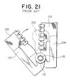
- This lateral-inserting type separable bottom end stop is disclosed, for example, in the specification of United States Patent No. 4139927, which is shown in FIG. 21.
- an incline surface having a screw-like configuration is provided at a portion of the periphery of each of the pin 110 and socket 112 of the male member 107 and the female member 108 which are provided at end portions of the left and right fastener stringers 102, 102.
- the fastener stringer 102 in order to rotate the fastener stringer 102 in the opposite direction and separate the pin 110 from the socket 112, the fastener stringer 102 must be rotated to a great extent, or else the fastener stringer 102 at the socket side must be twisted and detached. Thus there is the problem that the engagement and separation operations are extremely difficult.
- the present invention obviates the aforementioned problems and has a principal object to provide a lateral-inserting type separable bottom end stop assembly of a slide fastener in which the engagement and separation operations are extremely simple and particularly, children and elderly people can perform the operation of closing of the left and right fastener stringers in a simple manner.
- Still another object of the invention is to provide a separable bottom end stop assembly of a slide fastener which automatically, speedily and accurately guides an insert plate to an inner portion of the slider which is held by a holding portion which opposes the insert plate.
- Still another object of the invention is to provide a separable bottom end stop assembly of a slide fastener in which by specifying the configuration of a sliding surface of slide plate of the male member or the female member, the operation can be effective and accurate, and the separation of the male member and the female member can be carried out simply.
- Still another object of the invention is to provide a separable bottom end stop assembly of a slide fastener in which by specifying the surface configuration of the slide plate of the male member or the female member, the engagement and separation of the male member and the female member and the opening and closing of the fastener chain can be carried out smoothly and easily.
- Still another object of the invention is to provide a separable bottom end stop assembly of a slide fastener in which by specifying the surface shape of the male member or the female member, the operation of initial movement of the slider attached at the separable bottom end stop assembly can be started simply and reliably using the finger tips.
- Still another object of the invention is to provide a separable bottom end stop assembly of a slide fastener in which by specifying the configuration of the slider which is adapted to be mounted to the fastener chain, even children and elderly people can carry out the engagement and separation operation smoothly while the male member and the female member are visible.
- a lateral-inserting type separable bottom end stop assembly which comprises a male member and a female member which are engageable with and releasable from each other.
- the male member is provided with a first slide plate from which an engagement leg portion projects, while the female member is provided with a second sliding plate in which an engagement hole is formed to be fitly engaged with the engagement leg portion.
- First and second sliding surfaces are formed respectively at the peripheries of the engagement leg portion and the engagement hole.
- Each of the first and second slide surfaces is formed with a steep incline surface and a gentle incline surface.
- the steep incline surface and the gentle incline surface serve to automatically advance an insert plate which is disposed at one of the male member and the female member to an inside of a slider which is held by a holding portion which is disposed at the other of the male member and the female member when the first and second slide plates are pressed from both surfaces thereof.
- the insert plate can be automatically and speedily moved towards the slider which is held at the holding portion due to the action of the cam. Consequently the operation can be carried out easily even by children and elderly people or by using only one hand. Further, when the male member and the female member are opened to a certain extent, the male member and the female member can be automatically taken out from each other due to the action of the cam, thereby making the engagement and release operation extremely easy.
- the steep incline surface disposed at each of the slide surfaces is continuous to the gentle incline surface, and the steep incline surface automatically advances the insert plate toward the slider which is held at the holding portion when the first and second sliding plates are pressed from both surfaces thereof, and the gentle incline surface automatically guides the insert plate to the inside of the slider to be accommodated therein.
- the steep incline surface causes the insert plate to be automatically and speedily brought in close proximity with the slider which is held at the holding portion.
- the gentle incline surface maintains the action of the steep incline surface and guides the insert plate which is in contact with the slider to the inside of the slider automatically and accurately so that it is accommodated therein.
- the "steep incline surface” is a surface having a larger inclination than the "gentle incline surface”.
- each of the first and second slide surfaces has an elevation angle of 50-70 degrees, and the gentle incline surface has an elevation angle of 5-10 degrees.
- each of the first and second slide surfaces is provided with an upper step horizontal surface and a lower step horizontal surface which are disposed through a step. Consequently the engagement and release of the male member and the female member can be achieved easily and simply under optimum conditions.
- first steep incline surface a gentle incline surface, further preferably a second steep incline surface, which are inclined at different angles with respect to the horizontal surfaces, successively in the direction from the lower step horizontal surface towards the upper step horizontal surface. Consequently the insert plate can be automatically and speedily brought in close proximity with the slider which is held at the holding portion more easily, and can be guided and inserted into the slider automatically and accurately.
- each of the slide surfaces is provided with a vertical surface at a holding portion or an insert plate side thereof, and the upper step horizontal surface and the lower step horizontal surface are provided on both sides of the vertical surface, and the steep incline surface has a starting point which is between 160° and 170° from the vertical surface about the center of the engagement leg portion and the engagement hole, and the gentle incline surface is provided between 50° to 60° from an end point the steep incline surface. Consequently the steep incline surface and the gentle incline surface are disposed at the optimal positions, so that the advancing operation of the insert plate can be carried out accurately and the female member can be separated from the male member naturally and without resistance.
- grip portions are formed with an outer side edge of a front surface of the first slide plate of the male member and an outer side edge of a front surface of the second slide plate of the female member respectively such that said grip portions form thick portions. Consequently the separable bottom end stop assembly can be easy to grip, so that all the operations can be carried out easily.
- a surface of the second slide plate of the female member facing the insert plate has a gentle slant, which pushes the slider forward when the operation for closing the male member and the female member is carried out.
- the slider which is attached to the fastener stringer is the one having a semi-automatic stopping device.
- the slider is in a release state. That is, when a pull of the slider is caused to fall to a shoulder side of the slider body, and when the pull is caused to stand on the slider body, a locking pawl of the slider is pulled up so as to maintain a state that the stop operation cannot be carried out. Consequently the pull of the slider is prevented from being an obstruction at the time of the engagement and release operation of the separable bottom end stop assembly, and the engaging mechanism is directly visible so that the engagement and release operation can be carried out quickly and easily.
- the separable bottom end stop assembly of a slide fastener is a lateral-inserting type shown in FIG. 1.
- a male member 7 and a female member 8 having a pin or an engagement leg portion 11 and a socket or an engagement hole 12 respectively are attached to disc-shaped slides plates 9 and 10 of left and right fastener stringers 2, 2 of the slide fastener.
- the sliding plates 9 and 10 of the male member 7 and the female member 8 are superposed and when pressed from both front and back directions, the engagement leg portion 11 and the engagement hole 12 are engaged, and at the same time the sliding plate 10 of the female member 8 is automatically rotated around the engagement leg portion 11 in a horizontal direction thereof.
- an insert plate 30 of the female member 8 is inserted between guide flanges 44 of a slider 3 which is held by a holding portion 21 of the male member 7.
- the sliding plate 10 is further rotated automatically, so that the insert plate 30 is advanced into an inner portion of the slider.
- the insert plate 30 is inserted into a concave insert portion 22 of the male member 7, so that the fastener chain is thereby closed.
- Respective end portions of fastener tapes 4, 4 are reinforced by pressing reinforcing tapes 6, 6 which are formed of thermoplastic resin films to both front and back surfaces of the fastener tapes 4, 4.
- the male member 7 and the female member 8 are formed integrally with front surfaces of the reinforcement tapes 6, 6 using thermoplastic resin such as polyamide, polyacetal, polypropylene, polybutylene terephthalate by injection molding means so to be continuous with the fastener elements 5.
- thermoplastic resin such as polyamide, polyacetal, polypropylene, polybutylene terephthalate by injection molding means so to be continuous with the fastener elements 5.
- the separable bottom end stop assembly may also be formed using thermohardening resin or formed by metal die-casting.
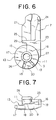
- the male member 7 which is attached so as to be integral with the end portion of one of the fastener stringers 2, is as shown in FIGS. 6 and 7, provided with a circular slide plate 9 at a front terminal end thereof.
- an engagement leg portion 11 which is a pin, is provided so as to project from the front surface thereof.
- An enlarged engagement head portion 26 is provided at a front end of the engagement leg portion 11 so as to project sideways. Further, a concave portion 27 is provided on an inner side surface of the engagement head portion 26.
- a slide surface 13 having a step is formed at the periphery of the base portion of the engagement leg portion 11 of the slide plate 9, a slide surface 13 having a step is formed.
- This slide surface 13 is circular, and has a vertical surface 15 at the portion along the side edge of the fastener tape 4, that is, from the holding portion 21 side toward the center of the engagement leg portion 11.
- An upper step horizontal surface 16 and a lower step horizontal surface 17 are disposed such that the vertical surface 15 is interposed therebetween.
- the lower step horizontal surface 17 projects from the side edge of the fastener stringer 2 to the outer side thereof, while the upper step horizontal surface 16 is provided so as to be positioned from the side edge of the fastener stringer 2 toward the inner side thereof.
- a first steep incline surface 18 is provided at a position of approximately 165° from the vertical surface 15 in the horizontal direction.
- the first steep incline surface 18 is formed with an elevation angle approximately in the range from 50° to 70°.
- a gentle incline surface 20 having an elevation angle of approximately 5° to 10°is provided so as to extend between the ranges of approximately 50° and 60 °about the center of the engagement leg portion 11.
- the terminal end of the gentle incline surface 20 is provided with a second steep incline surface 19 which has an elevation angle of 50- 70° and this is provided so as to be continuous to the upper step horizontal surface 16. Consequently, a continuous slide surface 13 having a cam mechanism is formed.
- a thick external portion 23 which protrude from the slide surface 13 is provided at the fastener element 5 side, and a stop portion 25 for stopping the slider 3 which is one step lower is provided at the external portion 23 close to the slide surface 13.
- the inner edge of the stop portion 25 extends to the upper end side so as to accommodate the guide flange 44 of the slider 3.
- fastener elements 5 are attached continuously to the outer side of the stop portion 25.
- the stop portion 25 has a holding portion 21, which can hold the slider 3 and extends to the upper end side.
- Ann insert recess groove 22 is formed at the outer surface of the holding portion 21 such that the insert plate 30 of the female member 8 can be fit-inserted therein.
- a convex portion 29 which projects from the vertical surface 15 to the side is formed at the external portion 23 of the lower end of the holding portion 21. This convex portion 29 can be fit-inserted into the concave portion 37 of the female member 8.
- the back surface of the slide plate 9 projects to the outer side and forms a thick grip portion 28.
- the grip portion 28 has a plurality of grooves cut into the front surface thereof to provide a rough surface which prevents slipping so that the slide plate 9 can be easily gripped.
- the back surface of the slide plate 9 is formed with each of a thick external portion 23, a holding portion 21 for the slider 3, a guide surface 24 and a stop portion 25 in a similar manner to the front surface thereof.
- a female member 8, which opposes the male member 7, is provided at the end portion of the other side fastener stringer 2.
- the female member 8 has a circular slide plate 10 at the terminal end thereof, and an engagement hole 12 is formed in the center thereof as the socket.
- a small engagement ridge 35 is provided at the inner peripheral surface of the engagement hole 12 so as project toward the inner side from the thinnest portion thereof. This engagement ridge 35 engages with the engagement head portion 26 of the engagement leg portion 11 of the male member 7.
- the back side of this slide plate 10, that is, the front surface which opposes the slide surface 13, has a slide surface 14, which has a step formed at the periphery of the engagement hole 12.
- the slide surface 14 is circular and has a vertical surface at the portion along the side edge of the fastener tape 4, that is, from the insert plate 30 side to the center of the engagement hole 12.
- an upper step horizontal surface 16 and a lower step horizontal surface 17 are disposed such that the vertical surface 15 is interposed therebetween.
- the upper step horizontal surface 16 projects from the side edge of the fastener stringer 2 to the outer side thereof, while the lower step horizontal surface 17 is provided so as to be positioned from the side edge of the fastener stringer 2 toward the inner side thereof.
- the upper step horizontal surface 16 has a first steep incline surface 18 at a position of approximately 165° from the vertical surface 15 in the horizontal direction thereof.
- the first steep incline surface 18 is formed with an elevation angle approximately in the range from 50° to 70°.
- a gentle incline surface 20 having an elevation angle of approximately 5° to 10° is provided so as to extend between the ranges of approximately 50° and 60° about the center of the engagement leg portion 11.
- the terminal end of gentle incline surface 20 is provided with a second steep incline surface 19 which has an elevation angle of 50- 70° and this is provided so as to be continuous to the lower step horizontal surface 17. Consequently, a continuous slide surface 14 having a cam mechanism is formed.
- the slide surface 14 around the engagement hole 12 is provided with a suitable beveling 39 in a range from the thickest lower step horizontal surface 17 to the gentle incline surface 20 which is the second thickest and from the front surfaces of these surface to the engagement ridge 35 provided at the inner peripheral surface, so that the engagement head portion 26 of the male member 7 can be easily fit therein.
- the inner side edge of the stop portion 34 extends to the upper end and can accommodate the slider 3.
- an insert plate 30 having a flat guide surface 33 is formed at the front surface, so that the insert plate 30 can be inserted into the insert recess groove 22 of the male member 7.
- the upper end of the outer side edge of the insert plate 30 has a coupling portion 31 which can couple with the opposing fastener element 5.
- a concave portion 37 is provided near the front end of the stop portion 34 and can thus be fit together with the convex portion 29 of the male member 7.
- the front surface of the slide plate 10 is formed with a thick grip portion 36 at an outermost end thereof so as to project to the outer side.
- the grip portion 36 has a plurality of grooves cut into the front surface thereof to provide a rough surface which prevents slipping.
- the surface of the slide plate 10 in which the opposite sides of the grip portion 36 and the engagement hole 12 are joined is at a higher position than the external portion 32 as shown in FIG. 14, and accordingly, the external portion 32 is lower than the slide portion 10.
- an incline surface 38 which inclines gently toward the external portion 32 is formed at the end side.
- the external portion 32 has a stop portion 34 for stopping the slider close to the slide plate 10, and a concave portion 37 is provided close to the front end of the stop portion 34.
- the side edge of the external portion 37 extends to the upper end side and is formed so as to accommodate the slider 3.
- the front surface of the external portion 37 has a flat guide surface 33 and thus the insert plate 30 is formed.
- the coupling portion 31 is provided at the upper end of the outer side edge of the insert plate 30. The back side of these parts are configured in the same manner.
- the slider 3 which is fit-inserted and used in the fastener chain 1 having a male member 7 and a female member 8 is a slider having a semi-automatic stopping device and is generally called a semi-automatic slider.
- the slider 3 has an accommodation hole 45 through which a guide pillar 43 of the body 40 and the upper wing plate 42 has a pair of mounting portions 49 for mounting a pull 41.
- a claw hole 46 is formed at a rear opening side of the slider close to the mounting portions 49.
- a plate spring 47 which is to be mounted to the body 40 has an M-shaped cross section, and one end thereof is accommodated and fixed in the accommodating hole 45 while the other end has a locking pawl 48 which fits into the claw hole 46.
- a rubber plate 52 is attached to the pull 41 so as to impart flexibility thereto.
- FIG. 2 shows a state in which the male member 7 and the female member 8 attached to fastener stringers 2,2 are separated. From this state, first the slider 3 which has been inserted through the fastener stringer 2 having the male member 7 is pulled down to the holding portion 21 of the male member 7 and held therein. While the slider 3 causes the pull 41 to stand upright from the body 40 or when the pull 41 caused to fall to the shoulder side, the right and left fastener stringers 2, 2 are opened at approximately 70° about the center of the slide plate 9 or 10as shown in FIG. 3.
- the gentle incline surface 20 causes a force to be generated, which attempts to rotate the slide plate 10 of the female member 8 around the engagement leg portion 11.
- the gentle incline surface 20 of the slide surface 14 of the female member 8 slides on the upper step horizontal surface 16 of the slide surface 13 of the male member 7, and the lower step horizontal surface 17 of the slide surface 14 of the female member 8 slides and moves on the gentle incline surface 20 of the slide surface 13 of the male member 7.
- the steep incline surfaces 18 and 19 of both the slide surfaces 13 and 14 contact with each other, the slide plate 10 moves forcefully along the incline surfaces 18 and 19 in front and back directions thereof.
- the positional relationship between the slide surface 13 and the slide surface 14 is such that the lower step horizontal surface 17 of the slide surface 13 and the lower step horizontal surface 17 of the slide surface 14, and also the upper step horizontal surface 16 of the slide surface 13 and the upper step horizontal surface 16 of the slide surface 14 are in contact with each other.
- the steep incline surface 18, the gentle incline surface 20 and the second steep incline surface 19 of the slide surface 13 oppose the second steep incline surface 19, the gentle incline surface 20 and the first steep incline surface 18 of the slide surface 14 with a small space between each of them.
- the first steep incline surface 18 and the second steep incline surface 19 of the slide surface 13 of the male member 7 are about to oppose and contact the second steep incline surface 19 and the first steep incline surface 18 of the slide surface 14 of the female member 8.
- the insert plate 30 is quickly led between the guide flanges 44 of the slider 3. At this time force is applied by bringing the male member 7 close to the female member 8 on the back side thereof by using the index finger.
- the slider 3 When the fastener chain 1 is to be separated, the slider 3 is pulled down to the holding portion 21 of the male member 7. Then in a state in which the pull 41 is upright or made to fall towards the shoulder side, the female member 8 is opened and separated in the horizontal direction with respect to the male member 7. As a result, the second steep incline surface 19 of the slide surface 13 and the second steep incline surface 19 of the slide surface 14 contact each other. Due to the action of the cam, the engagement head portion 26 of the engagement leg portion 11 and the engagement projection 35 of the engagement hole 12 are automatically released, so that the slide plate 10 of the female member 8 can be easily removed from the slide plate 9 of male member 7. It is to be noted that the reference number 53 shown in FIG. 1 represents a top end stop for preventing the slider 3 from coming off from the stringer 2.
- FIGS. 16 to 20 is the same as that of the first embodiment except that configurations of the slide surfaces 13 and 14 of the sliding plates 9 and 10 on the male member 7 and the female member 8.
- the slide surface 13 of the male member 7 is, as shown in FIG. 16, formed with a vertical surface 15 at the holding portion 21 side, on opposite sides of which an upper step horizontal surface 16 and a lower step horizontal surface 17 are formed through a step.
- a steep incline surface 18 is provided at the lower step horizontal surface 17 so as to be disposed at a position of approximately 165° from the vertical surface 15 in the horizontal direction.
- the first steep incline surface 18 is formed with an elevation angle approximately in the range from 50° to 70°.
- a gentle incline surface 20 having an elevation angle of approximately 5° to 10°is provided so as to extend between the ranges of approximately 50° and 60° about the center of the engagement leg portion 11.
- the gentle incline surface 20 is continuous to the upper step horizontal surface 16.
- a slide surface 13 provided with a cam mechanism is formed.
- the difference between the first embodiment is in that the terminal end of the gentle incline surface 20 is not provided with a steep incline surface but contacts the upper step horizontal surface 16.
- the slide surface 14 of the female member 8 has a vertical surface 15 at the insert plate 30 side thereof.
- This vertical surface 15 is formed between the upper step horizontal surface 16 and the lower step horizontal surface 17.
- a steep incline surface 19 is provided at the lower step horizontal surface 17, which is at a position of approximately 165° from the vertical surface 15 in the horizontal direction thereof.
- the steep incline surface 19 is formed with an elevation angle approximately in the range from 50° to 70°.
- a gentle incline surface 20 having an elevation angle of approximately 5° to 10°is provided so as to extend between the ranges of approximately 50° and 60° about the center of the engagement hole 12.
- the terminal end of the gentle incline surface 20 connects to the upper step horizontal surface 16.
- a slide surface 14 provided with a cam mechanism is formed.
- the difference between this second embodiment and the first embodiment is in that the terminal end of the gentle incline surface 20 is not provided with a steep incline surface but contacts the upper step horizontal surface.
- the female member 8 is pushed upwards and the engaged state of the engagement head portion 26 of the engagement leg portion 11 and the engagement projection 35 of the engagement hole 12 is released, and the female member 8 is taken out and thus released.
- the steep incline surface 18, 19, the gentle incline surface 20 and the limiting conditions of the specified angles adopted in this invention can be suitably modified in accordance with the size of the fastener chain, the various uses of the fastener and the needs of the customers. However it is necessary to provide the cam mechanism.
Landscapes
- Slide Fasteners (AREA)
- Buckles (AREA)
Abstract
Description
- The present invention relates to separable bottom end stop assembly of a slide fastener. More particularly it relates to separable bottom end stop assembly of a lateral-inserting type slide fastener in which one of the separable bottom end stops attached to a lower end of a fastener stringer is a male member and the other is a female member, and after the male member and the female member are engaged from both surfaces of the fastener surface by a snapping system, the male member and the female member are caused to join up against each other from the transverse direction of the fastener, thereby fitting the fastener stringer inside the slider.
- In the separable bottom end stop assembly of a slide fastener which has been used in the past, a box pin and a box are attached to an end portion of one of left and right fastener stringers and an insert pin is attached to the other fastener stringer. When the left and right fastener stringers are to be closed, the slider is slid so as to contact the box, and then the insert pin is inserted into the element guide groove of the slider. Next, after the insert pin is inserted into the box, the slider is pulled upwards and caused to slide and the closing operation is thereby carried out. However, in this type of separable bottom end stop assembly in which the insert pin must be inserted in the box, the insertion operation is extremely difficult for children and elderly people.
- One known separable bottom end stop assembly which can be operated simply is a lateral-inserting type in which a male member having a projecting pin and a female member having a socket are provided at an end portion of the right and left fastener stringers so as to be engaged with each other, and the fastener stringer is fit-inserted from the side of the slider and thereby closed. This lateral-inserting type separable bottom end stop is disclosed, for example, in the specification of United States Patent No. 4139927, which is shown in FIG. 21. In the disclosed separable bottom end stop, an incline surface having a screw-like configuration is provided at a portion of the periphery of each of the
pin 110 andsocket 112 of themale member 107 and thefemale member 108 which are provided at end portions of the left andright fastener stringers pin 110, thefemale member 108 moves toward thepin 110 of themale member 107, so that the engagement and separation operation of themale member 107 and thefemale member 108 can be carried out. - In the separable bottom end stop of the above-described slide fastener which is shown in FIG. 21, when the right and
left stringers pin 110 after thepin 110 and thesocket 112 are engaged, it is necessary to lead one of thefastener stringers slider 103 using the hands in order to fit-insert the fastener stringer 102 into the slider. This is because the screw-shaped incline surface is formed at a fixed angle. Further, in order to rotate thefastener stringer 102 in the opposite direction and separate thepin 110 from thesocket 112, thefastener stringer 102 must be rotated to a great extent, or else the fastener stringer 102 at the socket side must be twisted and detached. Thus there is the problem that the engagement and separation operations are extremely difficult. - The present invention obviates the aforementioned problems and has a principal object to provide a lateral-inserting type separable bottom end stop assembly of a slide fastener in which the engagement and separation operations are extremely simple and particularly, children and elderly people can perform the operation of closing of the left and right fastener stringers in a simple manner. That is to say, it is a principal object of the present invention to provide a separable bottom end stop assembly of a slide fastener in which the male member and the female member comprising the separable bottom end stop assembly can be engaged from both front and back directions, and by pulling together the male member and the female member and pressing both front and back surfaces thereof, the fastener stringers are closed easily due to cam mechanism, thereby causing initial movement of the slider, and in which separation of the left and right fastener stringers can be easily prevented, and further the separation and release of the left and right fastener stringers can be easily carried out.
- Still another object of the invention is to provide a separable bottom end stop assembly of a slide fastener which automatically, speedily and accurately guides an insert plate to an inner portion of the slider which is held by a holding portion which opposes the insert plate.
- Still another object of the invention is to provide a separable bottom end stop assembly of a slide fastener in which by specifying the configuration of a sliding surface of slide plate of the male member or the female member, the operation can be effective and accurate, and the separation of the male member and the female member can be carried out simply.
- Still another object of the invention is to provide a separable bottom end stop assembly of a slide fastener in which by specifying the surface configuration of the slide plate of the male member or the female member, the engagement and separation of the male member and the female member and the opening and closing of the fastener chain can be carried out smoothly and easily.
- Still another object of the invention is to provide a separable bottom end stop assembly of a slide fastener in which by specifying the surface shape of the male member or the female member, the operation of initial movement of the slider attached at the separable bottom end stop assembly can be started simply and reliably using the finger tips.
- Still another object of the invention is to provide a separable bottom end stop assembly of a slide fastener in which by specifying the configuration of the slider which is adapted to be mounted to the fastener chain, even children and elderly people can carry out the engagement and separation operation smoothly while the male member and the female member are visible.
- The above described objects can be attained by a basic feature of the present invention, that is, a lateral-inserting type separable bottom end stop assembly which comprises a male member and a female member which are engageable with and releasable from each other. The male member is provided with a first slide plate from which an engagement leg portion projects, while the female member is provided with a second sliding plate in which an engagement hole is formed to be fitly engaged with the engagement leg portion. First and second sliding surfaces are formed respectively at the peripheries of the engagement leg portion and the engagement hole. At the time of engagement, the male member and the female member are rotatable relatively with the first and second sliding surfaces thereof being in slide contact with each other. Each of the first and second slide surfaces is formed with a steep incline surface and a gentle incline surface. The steep incline surface and the gentle incline surface serve to automatically advance an insert plate which is disposed at one of the male member and the female member to an inside of a slider which is held by a holding portion which is disposed at the other of the male member and the female member when the first and second slide plates are pressed from both surfaces thereof.
- With such structure, by simply pressing the first and second slide plates of the male member and the female member which are in an engaged state from the front and the back, the insert plate can be automatically and speedily moved towards the slider which is held at the holding portion due to the action of the cam. Consequently the operation can be carried out easily even by children and elderly people or by using only one hand. Further, when the male member and the female member are opened to a certain extent, the male member and the female member can be automatically taken out from each other due to the action of the cam, thereby making the engagement and release operation extremely easy.
- Furthermore it is preferable that the steep incline surface disposed at each of the slide surfaces is continuous to the gentle incline surface, and the steep incline surface automatically advances the insert plate toward the slider which is held at the holding portion when the first and second sliding plates are pressed from both surfaces thereof, and the gentle incline surface automatically guides the insert plate to the inside of the slider to be accommodated therein. The steep incline surface causes the insert plate to be automatically and speedily brought in close proximity with the slider which is held at the holding portion. Further, the gentle incline surface maintains the action of the steep incline surface and guides the insert plate which is in contact with the slider to the inside of the slider automatically and accurately so that it is accommodated therein.
- Here, the "steep incline surface" is a surface having a larger inclination than the "gentle incline surface".
- Still further, it is preferable that the steep incline surface disposed at each of the first and second slide surfaces has an elevation angle of 50-70 degrees, and the gentle incline surface has an elevation angle of 5-10 degrees. Further, it is preferable that each of the first and second slide surfaces is provided with an upper step horizontal surface and a lower step horizontal surface which are disposed through a step. Consequently the engagement and release of the male member and the female member can be achieved easily and simply under optimum conditions.
- Furthermore it is preferable that there are provided a first steep incline surface, a gentle incline surface, further preferably a second steep incline surface, which are inclined at different angles with respect to the horizontal surfaces, successively in the direction from the lower step horizontal surface towards the upper step horizontal surface. Consequently the insert plate can be automatically and speedily brought in close proximity with the slider which is held at the holding portion more easily, and can be guided and inserted into the slider automatically and accurately.
- Still further, it is preferable that each of the slide surfaces is provided with a vertical surface at a holding portion or an insert plate side thereof, and the upper step horizontal surface and the lower step horizontal surface are provided on both sides of the vertical surface, and the steep incline surface has a starting point which is between 160° and 170° from the vertical surface about the center of the engagement leg portion and the engagement hole, and the gentle incline surface is provided between 50° to 60° from an end point the steep incline surface. Consequently the steep incline surface and the gentle incline surface are disposed at the optimal positions, so that the advancing operation of the insert plate can be carried out accurately and the female member can be separated from the male member naturally and without resistance.
- Still further it is preferable that when the engagement leg portion of the male member and the engagement hole of the female member are engaged and the insert plate of the female member is fit-inserted into an insert recess groove provided in the holding portion of the male member, grip portions are formed with an outer side edge of a front surface of the first slide plate of the male member and an outer side edge of a front surface of the second slide plate of the female member respectively such that said grip portions form thick portions. Consequently the separable bottom end stop assembly can be easy to grip, so that all the operations can be carried out easily.
- Still further it is preferable that a surface of the second slide plate of the female member facing the insert plate has a gentle slant, which pushes the slider forward when the operation for closing the male member and the female member is carried out. With this structure it is possible to push the slider forward by the thumb easily, so that the movement of the slider can be started easily.
- According to the present invention, the slider which is attached to the fastener stringer is the one having a semi-automatic stopping device. When the engagement leg portion of the male member are engaged with the engagement hole of the female member in the left and right fastener stringers, and when the closing operation of the fastener chain is begun, the slider is in a release state. That is, when a pull of the slider is caused to fall to a shoulder side of the slider body, and when the pull is caused to stand on the slider body, a locking pawl of the slider is pulled up so as to maintain a state that the stop operation cannot be carried out. Consequently the pull of the slider is prevented from being an obstruction at the time of the engagement and release operation of the separable bottom end stop assembly, and the engaging mechanism is directly visible so that the engagement and release operation can be carried out quickly and easily.
-
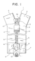
- FIG. 1 is a front view of a slide fastener including the lateral-inserting type separable bottom end stop assembly according to a first embodiment of the present invention.
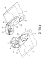
- FIG. 2 is a perspective view of a male member and a female member in a state in which the left and right fastener stringers are separated.
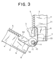
- FIG. 3 is a front view of the fastener chain in an open state.
- FIG. 4 is a front view of the state of the fastener chain immediately before the insert plate is inserted into the slider.
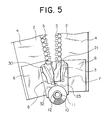
- FIG. 5 is a front view of the state of the fastener chain immediately before the closing thereof.
- FIG. 6 is a front view of the male member of the first embodiment.
- FIG. 7 is a bottom view of the male member of the first embodiment.
- FIG. 8 is a front view of the female member of the first embodiment.
- FIG. 9 is a bottom view of the female member of the first embodiment.
- FIG. 10 is a rear view of the female member of the first embodiment.
- FIG. 11 is a bottom view of the separable bottom end stop assembly at the time of closing of the fastener chain of the first embodiment.
- FIG. 12 is a bottom view of the separable bottom end stop immediately before the closing of the fastener chain of the first embodiment.
- FIG. 13 is a bottom view of the separable bottom end stop at the time of opening of the fastener chain of the first embodiment.
- FIG. 14 is a cross section of the male member and the female member in an engaged state.
- FIG. 15 is cross section of the slider having a semi-automatic stop device.
- FIG. 16 is a front view of a male member according to a second embodiment.
- FIG. 17 is a rear view of a male member of the second embodiment.
- FIG. 18 is a bottom view of the separable bottom end stop assembly at the time of closing of the fastener chain of the second embodiment.
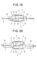
- FIG. 19 is a bottom view of the separable bottom end stop assembly immediately before closing of the fastener chain of the second embodiment.
- FIG. 20 is a bottom view of the separable bottom end stop assembly at the time of opening of the fastener chain of the second embodiment.
- FIG. 21 is a front view of the male member and the female member of a known separable bottom end stop assembly in a state in which they are engaged.
-
- The following is a detailed description of aspects of the separable bottom end stop assembly of a slide fastener of the present invention with reference to the accompanying drawings.
- The separable bottom end stop assembly of a slide fastener according to the present invention is a lateral-inserting type shown in FIG. 1. In the separable bottom end stop assembly, a
male member 7 and afemale member 8 having a pin or anengagement leg portion 11 and a socket or anengagement hole 12 respectively are attached to disc-shapedslides plates right fastener stringers plates male member 7 and thefemale member 8 are superposed and when pressed from both front and back directions, theengagement leg portion 11 and theengagement hole 12 are engaged, and at the same time the slidingplate 10 of thefemale member 8 is automatically rotated around theengagement leg portion 11 in a horizontal direction thereof. Consequently, aninsert plate 30 of thefemale member 8 is inserted betweenguide flanges 44 of aslider 3 which is held by a holdingportion 21 of themale member 7. The slidingplate 10 is further rotated automatically, so that theinsert plate 30 is advanced into an inner portion of the slider. Subsequently, when apull 41 of theslider 3 is pulled thereby sliding the slider, theinsert plate 30 is inserted into aconcave insert portion 22 of themale member 7, so that the fastener chain is thereby closed. - Respective end portions of
fastener tapes tapes fastener tapes male member 7 and thefemale member 8 are formed integrally with front surfaces of thereinforcement tapes fastener elements 5. It is to be noted that the separable bottom end stop assembly may also be formed using thermohardening resin or formed by metal die-casting. - In the first embodiment of the separable bottom end stop assembly shown in FIGS. 2 to 14, the
male member 7 which is attached so as to be integral with the end portion of one of thefastener stringers 2, is as shown in FIGS. 6 and 7, provided with acircular slide plate 9 at a front terminal end thereof. In the center of thisslide plate 9, anengagement leg portion 11, which is a pin, is provided so as to project from the front surface thereof. An enlargedengagement head portion 26 is provided at a front end of theengagement leg portion 11 so as to project sideways. Further, aconcave portion 27 is provided on an inner side surface of theengagement head portion 26. - At the periphery of the base portion of the
engagement leg portion 11 of theslide plate 9, aslide surface 13 having a step is formed. Thisslide surface 13 is circular, and has avertical surface 15 at the portion along the side edge of thefastener tape 4, that is, from the holdingportion 21 side toward the center of theengagement leg portion 11. An upper stephorizontal surface 16 and a lower stephorizontal surface 17 are disposed such that thevertical surface 15 is interposed therebetween. The lower stephorizontal surface 17 projects from the side edge of thefastener stringer 2 to the outer side thereof, while the upper stephorizontal surface 16 is provided so as to be positioned from the side edge of thefastener stringer 2 toward the inner side thereof. A firststeep incline surface 18 is provided at a position of approximately 165° from thevertical surface 15 in the horizontal direction. The firststeep incline surface 18 is formed with an elevation angle approximately in the range from 50° to 70°. In a direction from the firststeep incline surface 18 to the upper stephorizontal surface 16, agentle incline surface 20 having an elevation angle of approximately 5° to 10°is provided so as to extend between the ranges of approximately 50° and 60 °about the center of theengagement leg portion 11. The terminal end of thegentle incline surface 20 is provided with a secondsteep incline surface 19 which has an elevation angle of 50- 70° and this is provided so as to be continuous to the upper stephorizontal surface 16. Consequently, acontinuous slide surface 13 having a cam mechanism is formed. - A thick
external portion 23 which protrude from theslide surface 13 is provided at thefastener element 5 side, and astop portion 25 for stopping theslider 3 which is one step lower is provided at theexternal portion 23 close to theslide surface 13. The inner edge of thestop portion 25 extends to the upper end side so as to accommodate theguide flange 44 of theslider 3. Also,fastener elements 5 are attached continuously to the outer side of thestop portion 25. Thestop portion 25 has a holdingportion 21, which can hold theslider 3 and extends to the upper end side. Anninsert recess groove 22 is formed at the outer surface of the holdingportion 21 such that theinsert plate 30 of thefemale member 8 can be fit-inserted therein. - A
guide surface 24, which can slide theguide flange 44 of theslider 3 having a concave surface, is formed between the holdingportion 21 and the inner side edge of thestop portion 25. Aconvex portion 29 which projects from thevertical surface 15 to the side is formed at theexternal portion 23 of the lower end of the holdingportion 21. Thisconvex portion 29 can be fit-inserted into theconcave portion 37 of thefemale member 8. As shown in FIG. 14, the back surface of theslide plate 9 projects to the outer side and forms athick grip portion 28. Thegrip portion 28 has a plurality of grooves cut into the front surface thereof to provide a rough surface which prevents slipping so that theslide plate 9 can be easily gripped. In addition, the back surface of theslide plate 9 is formed with each of a thickexternal portion 23, a holdingportion 21 for theslider 3, aguide surface 24 and astop portion 25 in a similar manner to the front surface thereof. - A
female member 8, which opposes themale member 7, is provided at the end portion of the otherside fastener stringer 2. As shown in FIGS. 8, 9 and 10, thefemale member 8 has acircular slide plate 10 at the terminal end thereof, and anengagement hole 12 is formed in the center thereof as the socket. Asmall engagement ridge 35 is provided at the inner peripheral surface of theengagement hole 12 so as project toward the inner side from the thinnest portion thereof. Thisengagement ridge 35 engages with theengagement head portion 26 of theengagement leg portion 11 of themale member 7. - The back side of this
slide plate 10, that is, the front surface which opposes theslide surface 13, has aslide surface 14, which has a step formed at the periphery of theengagement hole 12. Theslide surface 14 is circular and has a vertical surface at the portion along the side edge of thefastener tape 4, that is, from theinsert plate 30 side to the center of theengagement hole 12. As with theslide surface 13 of themale member 7, an upper stephorizontal surface 16 and a lower stephorizontal surface 17 are disposed such that thevertical surface 15 is interposed therebetween. The upper stephorizontal surface 16 projects from the side edge of thefastener stringer 2 to the outer side thereof, while the lower stephorizontal surface 17 is provided so as to be positioned from the side edge of thefastener stringer 2 toward the inner side thereof. The upper stephorizontal surface 16 has a firststeep incline surface 18 at a position of approximately 165° from thevertical surface 15 in the horizontal direction thereof. The firststeep incline surface 18 is formed with an elevation angle approximately in the range from 50° to 70°. In a direction from theincline surface 18 to the lower stephorizontal surface 17, agentle incline surface 20 having an elevation angle of approximately 5° to 10° is provided so as to extend between the ranges of approximately 50° and 60° about the center of theengagement leg portion 11. The terminal end ofgentle incline surface 20 is provided with a secondsteep incline surface 19 which has an elevation angle of 50- 70° and this is provided so as to be continuous to the lower stephorizontal surface 17. Consequently, acontinuous slide surface 14 having a cam mechanism is formed. - The
slide surface 14 around theengagement hole 12 is provided with asuitable beveling 39 in a range from the thickest lower stephorizontal surface 17 to thegentle incline surface 20 which is the second thickest and from the front surfaces of these surface to theengagement ridge 35 provided at the inner peripheral surface, so that theengagement head portion 26 of themale member 7 can be easily fit therein. - A thick
external portion 32 which protrude from theslide surface 14 to the surface, that is, the surface which opposes theslide surface 13, is provided at thefastener element 5 side, and astop portion 34 for stopping theslider 3 which is one step lower is provided at theexternal portion 32 close to theslide surface 14. The inner side edge of thestop portion 34 extends to the upper end and can accommodate theslider 3. Also, aninsert plate 30 having aflat guide surface 33 is formed at the front surface, so that theinsert plate 30 can be inserted into theinsert recess groove 22 of themale member 7. Also, the upper end of the outer side edge of theinsert plate 30 has acoupling portion 31 which can couple with the opposingfastener element 5. Further, aconcave portion 37 is provided near the front end of thestop portion 34 and can thus be fit together with theconvex portion 29 of themale member 7. - As shown in FIG. 14, the front surface of the
slide plate 10 is formed with athick grip portion 36 at an outermost end thereof so as to project to the outer side. Thegrip portion 36 has a plurality of grooves cut into the front surface thereof to provide a rough surface which prevents slipping. The surface of theslide plate 10 in which the opposite sides of thegrip portion 36 and theengagement hole 12 are joined is at a higher position than theexternal portion 32 as shown in FIG. 14, and accordingly, theexternal portion 32 is lower than theslide portion 10. In addition, anincline surface 38 which inclines gently toward theexternal portion 32 is formed at the end side. By providing thisincline surface 38, when themale member 7 and thefemale member 8 are pressed together from the front and back with the fingers, the fingers can slide on theincline surface 38, so that theslider 3 can be pushed forward when the closing operation of the fastener chain 1 is carried out. - The
external portion 32 has astop portion 34 for stopping the slider close to theslide plate 10, and aconcave portion 37 is provided close to the front end of thestop portion 34. The side edge of theexternal portion 37 extends to the upper end side and is formed so as to accommodate theslider 3. The front surface of theexternal portion 37 has aflat guide surface 33 and thus theinsert plate 30 is formed. Further, thecoupling portion 31 is provided at the upper end of the outer side edge of theinsert plate 30. The back side of these parts are configured in the same manner. - Next, as shown in FIG. 15, the
slider 3 which is fit-inserted and used in the fastener chain 1 having amale member 7 and afemale member 8 is a slider having a semi-automatic stopping device and is generally called a semi-automatic slider. Theslider 3 has anaccommodation hole 45 through which aguide pillar 43 of thebody 40 and theupper wing plate 42 has a pair of mountingportions 49 for mounting apull 41. Aclaw hole 46 is formed at a rear opening side of the slider close to the mountingportions 49. Aplate spring 47 which is to be mounted to thebody 40 has an M-shaped cross section, and one end thereof is accommodated and fixed in theaccommodating hole 45 while the other end has a lockingpawl 48 which fits into theclaw hole 46. Apull 41 having a semicircular-shapedcam 50, whose pivot is formed above the lockingpawl 48, is disposed at the lower side of theplate spring 47 and attached to theattachment portion 49. Arubber plate 52 is attached to thepull 41 so as to impart flexibility thereto. - When the
slider 3 causes thepull 41 to become upright from thebody 40 and when thepull 41 is caused to fall at the shoulder side, that is, in the forward direction, theplate spring 47 is automatically lifted up by the semicircular cam of thepull 41, so that the lockingpawl 48 is caused to come up out of theguide groove 51 of thebody 40. As a result, theslider 3 is slid automatically. When theslider 3 is to be stopped, because if thepull 41 is disposed in a hanging state with respect to thebody 40, thecam 50 does not operate. Therefore the lockingpawl 48 is inserted between the fastener elements and theslider 3 is stopped. - The following describes the separable bottom end stop assembly of the present invention in a state of use. FIG. 2 shows a state in which the
male member 7 and thefemale member 8 attached tofastener stringers slider 3 which has been inserted through thefastener stringer 2 having themale member 7 is pulled down to the holdingportion 21 of themale member 7 and held therein. While theslider 3 causes thepull 41 to stand upright from thebody 40 or when thepull 41 caused to fall to the shoulder side, the right and leftfastener stringers slide plate 9 or 10as shown in FIG. 3. In this state, when theengagement leg portion 11 of themale member 7 and theengagement hole 12 of thefemale member 8 are brought together and then forcefully pressed together, as shown in FIG. 13, theengagement head portion 26 and theengagement ridge 35 are engaged and cannot be removed from each other. At this time, the positional relationship between theslide surface 13 and theslide surface 14 is such that thegentle incline surface 20 of theslide surface 13 and the lower stephorizontal surface 17 of theslide surface 14 are joined together and thegentle incline surface 20 of theslide surface 14 and the upper stephorizontal surface 16 of theslide surface 13 are joined together. - When the
slide plates male member 7 and thefemale member 8 are forcefully pressed from the back and front, thegentle incline surface 20 causes a force to be generated, which attempts to rotate theslide plate 10 of thefemale member 8 around theengagement leg portion 11. Thegentle incline surface 20 of theslide surface 14 of thefemale member 8 slides on the upper stephorizontal surface 16 of theslide surface 13 of themale member 7, and the lower stephorizontal surface 17 of theslide surface 14 of thefemale member 8 slides and moves on thegentle incline surface 20 of theslide surface 13 of themale member 7. When the steep incline surfaces 18 and 19 of both the slide surfaces 13 and 14 contact with each other, theslide plate 10 moves forcefully along the incline surfaces 18 and 19 in front and back directions thereof. As a result, a great rotational force is applied to theslide plate 10, and as shown in FIG. 4, thefemale member 8 is rotated until the front end of theinsert plate 30 is positioned between theflanges 44 of theslider 3. The positional relationship between theslide surface 13 and theslide surface 14 at this time, is as shown in FIG. 12, such that thegentle incline surface 20 of theslide surface 13 contacts with thegentle incline surface 20 of theslide surface 14, and the firststeep incline surface 18 of theslide surface 13 contacts the secondsteep incline surface 19 of theslide surface 14 and the secondsteep incline surface 19 of theslide surface 13 contacts the firststeep incline surface 18 of theslide surface 14, and there are small gaps between the upper stephorizontal surface 16 of theslide surface 13 and the upper stephorizontal surface 16 of theslide surface 14 and between the lower stephorizontal surface 17 of theslide surface 13 and the lower stephorizontal surface 17 of theslide surface 14. - Subsequently, by the movement of the
gentle incline surface 20 of theslide surface 14 of thefemale member 8 along thegentle incline surface 20 of theslide surface 13 of themale member 7, the rotational force applied to thefemale member 8 is maintained and further rotates thefemale member 8. Then, as shown in FIG. 5, theinsert plate 30 is guided and inserted to the inner portion of theslider 3. In addition, when theslider 3 is pulled up and the left andright fastener stringers vertical surfaces male member 7 and thefemale member 8 are brought into contact with each other. At this time, the positional relationship between theslide surface 13 and theslide surface 14 is such that the lower stephorizontal surface 17 of theslide surface 13 and the lower stephorizontal surface 17 of theslide surface 14, and also the upper stephorizontal surface 16 of theslide surface 13 and the upper stephorizontal surface 16 of theslide surface 14 are in contact with each other. Thesteep incline surface 18, thegentle incline surface 20 and the secondsteep incline surface 19 of theslide surface 13 oppose the secondsteep incline surface 19, thegentle incline surface 20 and the firststeep incline surface 18 of theslide surface 14 with a small space between each of them. - As can also be understood from the above description, even when the
male member 7 and thefemale member 8 are rotated from the state shown in FIGS. 4 and 12 to the state shown FIGS. 1 and 11, themale member 7 and thefemale member 8 do not move relatively in a vertical direction, but move only in the horizontal direction. Accordingly in the state of FIG. 4, the side edge of theinsert plate 30 of thefemale member 8 oppose theinsert recess groove 22 of themale member 7 between theguide flanges 44 of theslider 3 and can move horizontally to be inserted therein. - Immediately before the state shown in FIG. 4, the first
steep incline surface 18 and the secondsteep incline surface 19 of theslide surface 13 of themale member 7 are about to oppose and contact the secondsteep incline surface 19 and the firststeep incline surface 18 of theslide surface 14 of thefemale member 8. By pressing theslide plate 9 of themale member 7 and theslide plate 10 of thefemale member 8 at the back and front thereof with even one hand, the steep incline surfaces contact each other and due to the action of the cam, theinsert plate 30 is quickly led between theguide flanges 44 of theslider 3. At this time force is applied by bringing themale member 7 close to thefemale member 8 on the back side thereof by using the index finger. Further by pushing the front surface of thefemale member 8 with the thumb forward, the rear opening portion of theslider 3 is pressed with the force and theslider 3 can be slid forward to a small extent with only one hand. As a result, the right and leftfastener stringers fastener elements 5, and thus subsequently if thepull 41 of theslider 3 is pulled forward, the fastener chain 1 can be closed as shown in FIG. 1. - When the fastener chain 1 is to be separated, the
slider 3 is pulled down to the holdingportion 21 of themale member 7. Then in a state in which thepull 41 is upright or made to fall towards the shoulder side, thefemale member 8 is opened and separated in the horizontal direction with respect to themale member 7. As a result, the secondsteep incline surface 19 of theslide surface 13 and the secondsteep incline surface 19 of theslide surface 14 contact each other. Due to the action of the cam, theengagement head portion 26 of theengagement leg portion 11 and theengagement projection 35 of theengagement hole 12 are automatically released, so that theslide plate 10 of thefemale member 8 can be easily removed from theslide plate 9 ofmale member 7. It is to be noted that thereference number 53 shown in FIG. 1 represents a top end stop for preventing theslider 3 from coming off from thestringer 2. - Finally the second embodiment of the separable bottom end stop assembly is shown in FIGS. 16 to 20, which is the same as that of the first embodiment except that configurations of the slide surfaces 13 and 14 of the sliding
plates male member 7 and thefemale member 8. Theslide surface 13 of themale member 7 is, as shown in FIG. 16, formed with avertical surface 15 at the holdingportion 21 side, on opposite sides of which an upper stephorizontal surface 16 and a lower stephorizontal surface 17 are formed through a step. Asteep incline surface 18 is provided at the lower stephorizontal surface 17 so as to be disposed at a position of approximately 165° from thevertical surface 15 in the horizontal direction. The firststeep incline surface 18 is formed with an elevation angle approximately in the range from 50° to 70°. In a direction from theincline surface 18 to the upper stephorizontal surface 16, agentle incline surface 20 having an elevation angle of approximately 5° to 10°is provided so as to extend between the ranges of approximately 50° and 60° about the center of theengagement leg portion 11. Thegentle incline surface 20 is continuous to the upper stephorizontal surface 16. As a result, aslide surface 13 provided with a cam mechanism is formed. Thus the difference between the first embodiment is in that the terminal end of thegentle incline surface 20 is not provided with a steep incline surface but contacts the upper stephorizontal surface 16. - In addition, as shown in FIG. 17, the
slide surface 14 of thefemale member 8 has avertical surface 15 at theinsert plate 30 side thereof. Thisvertical surface 15 is formed between the upper stephorizontal surface 16 and the lower stephorizontal surface 17. Asteep incline surface 19 is provided at the lower stephorizontal surface 17, which is at a position of approximately 165° from thevertical surface 15 in the horizontal direction thereof. Thesteep incline surface 19 is formed with an elevation angle approximately in the range from 50° to 70°. In a direction from thesteep incline surface 19 to the upper stephorizontal surface 16, agentle incline surface 20 having an elevation angle of approximately 5° to 10°is provided so as to extend between the ranges of approximately 50° and 60° about the center of theengagement hole 12. The terminal end of thegentle incline surface 20 connects to the upper stephorizontal surface 16. As a result, aslide surface 14 provided with a cam mechanism is formed. Thus the difference between this second embodiment and the first embodiment is in that the terminal end of thegentle incline surface 20 is not provided with a steep incline surface but contacts the upper step horizontal surface. - The positional relationship of the joining of the
slide surface 13 of themale member 7 and theslide surface 14 of thefemale member 8 according to the second embodiment will be described in the following. In order to engage theengagement head portion 26 of theengagement leg portion 11 and theengagement ridge 35 of theengagement hole 12, as shown in FIG. 20, the engagement is carried out at the time when thesteep incline surface 19 of theslide surface 14 joins with thegentle incline surface 20 of theslide surface 13. In the state when theinsert plate 30 is inserted between theguide flanges 44 of theslider 3, as shown in FIG. 19, thesteep incline surface 18 and thegentle incline surface 20 of theslide surface 13 oppose and come in contact with thegentle incline surface 20 and thesteep incline surface 19 of theslide surface 14 and there are small gaps between the upper stephorizontal surface 16 of theslide surface 13 and the upper stephorizontal surface 16 of theslide surface 14 and between the lower stephorizontal surface 17 of theslide surface 13 and the lower stephorizontal surface 17 of theslide surface 14. In addition, in the state in which thevertical surfaces 15 are in contact with each other, when the slide surfaces 13 and 14 are joined together, there is a small space between thesteep incline surface 18 and thegentle incline surface 20 of theslide surface 13, and thesteep incline surface 19 and thegentle incline surface 20 of theslide surface 14, as shown in FIG. 18. - Even with the above-described configurations of the
slide surface 13 of themale member 7 and theslide surface 14 of thefemale member 8, when theslide plate 9 of themale member 7 and theslide plate 10 of thefemale member 8 are, as is the case in the first embodiment, pressed at the front and back with only one hand while themale member 7 and thefemale member 8 are at such a position as being opened at approximately 30°, the steep incline surfaces 18 and 19 can be brought into contact with each other. Due to the action of the cam, theinsert plate 30 can be led speedily between theguide flanges 44 of theslider 3. Further force is applied by using the index finger to bring thefemale member 8 close themale member 7, and by pushing the front surface of thefemale member 8 with the thumb forward, the rear opening portion of theslider 3 is pressed with force, so that theslider 3 can be easily slid forward to a small extent with only one hand, thus completing the fitting together of themale member 7 and thefemale member 8. - Further, in order to separate and release the
male member 7 and thefemale member 8, from the state shown in FIG. 20, if they are opened by about 90° for example, the lower end corner portion of thesteep incline surface 19 of thefemale member 8 abuts thegentle incline surface 20 of themale member 7 near the terminal end thereof. Consequently, thefemale member 8 is pushed upwards and the engaged state of theengagement head portion 26 of theengagement leg portion 11 and theengagement projection 35 of theengagement hole 12 is released, and thefemale member 8 is taken out and thus released. - It is to be noted that the
steep incline surface gentle incline surface 20 and the limiting conditions of the specified angles adopted in this invention can be suitably modified in accordance with the size of the fastener chain, the various uses of the fastener and the needs of the customers. However it is necessary to provide the cam mechanism.
Claims (9)
- A separable bottom end stop assembly for a slide fastener comprising a male member (7) and a female member (8) which are engageable with and releasable from each other, in which said male member (7) is provided with a first slide plate (9) from which an engagement leg portion (11) projects, said female member (8) is provided with a second slide plate (10) in which an engagement hole (12) is formed to be fitly engaged with the engagement leg portion (11), first and second sliding surfaces (13) and (14) are respectively formed at peripheries of the engagement leg portion (11) and the engagement hole (12), and at the time of engagement, the male member (7) and the female member (8) are rotatable respectively with the first and second slide surfaces (13) and (14) being in slide contact with each other, being characterized in that
each of the first and second slide surfaces (13) and (14) is formed with a steep incline surface (18, 19) and a gentle incline surface (20), said steep incline surface (18, 19) and said gentle incline surface (20) automatically advancing an insert plate (30) which is disposed at one of the male member (7) and the female member (8) to an inside of a slider (3) which is held by a holding portion which is disposed at the other of the male member (7) and the female member (8) when said first and second slide plates (9) and (10) are pressed from both surfaces thereof. - The separable bottom end stop assembly for a slide fastener according to claim 1, characterized in that the steep incline surface (18, 19) is continuous to the gentle incline surface (20), and the steep incline surface (18, 19) automatically advances the insert plate (30) toward the slider (3) which is held at the holding portion (21) when the first and second sliding plates (9, 10) are pressed from both surfaces thereof, and the gentle incline surface (20) automatically guides the insert plate (30) to the inside of the slider (3).
- The separable bottom end stop assembly for a slide fastener according to claim 1, characterized in that the steep incline surface (18, 19) inclines at angle of 50° to 70°, and the gentle incline surface (20) inclines at an angle of 5° to 10°.
- The separable bottom end stop assembly for a slide fastener according to claim 1, characterized in that each of the slide surfaces (13) and (14) includes an upper step horizontal surface (16) and a lower step horizontal surface (17) which are disposed through a step, and said steep incline surface (18, 19) includes a first steep incline surface (18) and a second steep incline surface (19), said first steep incline surface (18), said gentle incline surface (20), and said second steep incline surface (19), which incline at different angles with respect to both the upper and lower step horizontal surfaces (16) and (17), being provided successively in a direction from the lower step horizontal surface (17) to the upper step horizontal surface (16).
- The separable bottom end stop assembly for a slide fastener according to claim 1, characterized in that each of the slide surfaces (13) and (14) includes an upper step horizontal surface (16) and a lower step horizontal surface (17) which are disposed through a step, said steep incline surface (18) and said gentle incline surface (20), which incline at different angles with respect to both the upper and lower step horizontal surfaces (16) and (17), being provided successively in a direction from the lower step horizontal surface (17) to the upper step horizontal surface (16).
- The separable bottom end stop assembly for a slide fastener according to claim 4 or 5, characterized in that each of the first and second slide surfaces (13) and (14) is provided with a vertical surface (15) at a side of said holding portion (21) or said insert plate (30), and the upper step horizontal surface (16) and the lower step horizontal surface (17) are provided on both sides of said vertical surface (15), and said steep incline surface (18, 19) is provided so as to have a starting point between 160° and 170° from the vertical surface (15) about a center of the engagement leg portion (11) and the engagement hole (12), and the gentle incline surface (20) is provided between 50° to 60° from an end point of the steep incline surface (18).
- The separable bottom end stop assembly for a slide fastener according to claim 1, characterized in that when the male member (7) and the female member (8) are engaged and the insert plate (30) is inserted into an insert recess groove (22) of said holding portion (21), grip portions (28) and (36) are formed with an outer side edge of a front surface of the first slide plate (9) of the male member (7) and an outer side edge of a front surface of the second slide plate (10) of the female member (8) respectively such that said grip portions (28) and (36) form thick portions.
- The separable bottom end stop assembly for a slide fastener according to claim 1, characterized in that a surface of the second slide plate (10) of the female member (8) facing the insert plate (30) has a gentle slant (38), which can push said slider (3) forward when the closing operation is carried out.
- The separable bottom end stop assembly for a slide fastener according to claim 1, characterized in that the slider (3) which is attached to a fastener stringer (2) is a slider having a semi-automatic stopping device, and the when the male member (7) and the female member (8) of the left and right fastener stringers (2, 2) are engaged and when the closing operation of a fastener chain (1) is initiated, the slider (3) is attached in a state such that it can be maintained in a release state.
Applications Claiming Priority (2)
| Application Number | Priority Date | Filing Date | Title |
|---|---|---|---|
| JP2002145065 | 2002-05-20 | ||
| JP2002145065A JP3733343B2 (en) | 2002-05-20 | 2002-05-20 | Separation insert for slide fastener |
Publications (2)
| Publication Number | Publication Date |
|---|---|
| EP1364592A1 true EP1364592A1 (en) | 2003-11-26 |
| EP1364592B1 EP1364592B1 (en) | 2005-04-27 |
Family
ID=29397746
Family Applications (1)
| Application Number | Title | Priority Date | Filing Date |
|---|---|---|---|
| EP03253150A Expired - Lifetime EP1364592B1 (en) | 2002-05-20 | 2003-05-20 | Separable bottom end stop assembly for slide fastener |
Country Status (8)
| Country | Link |
|---|---|
| US (1) | US6826810B2 (en) |
| EP (1) | EP1364592B1 (en) |
| JP (1) | JP3733343B2 (en) |
| KR (1) | KR100465473B1 (en) |
| CN (1) | CN1228009C (en) |
| DE (1) | DE60300559T2 (en) |
| ES (1) | ES2240915T3 (en) |
| TW (1) | TW586915B (en) |
Cited By (3)
| Publication number | Priority date | Publication date | Assignee | Title |
|---|---|---|---|---|
| GB2441144A (en) * | 2006-08-23 | 2008-02-27 | Touac Internat Ltd | Zip fastener with separable bottom stop which retains slider |
| GB2483429A (en) * | 2010-08-26 | 2012-03-14 | Ykk Europ Ltd | Slide fastener bottom stop |
| US9883202B2 (en) | 2006-10-06 | 2018-01-30 | Nxp Usa, Inc. | Scaling video processing complexity based on power savings factor |
Families Citing this family (34)
| Publication number | Priority date | Publication date | Assignee | Title |
|---|---|---|---|---|
| JP4464802B2 (en) * | 2004-11-30 | 2010-05-19 | Ykk株式会社 | fastener |
| JP4628329B2 (en) * | 2006-08-17 | 2011-02-09 | Ykk株式会社 | Slide fastener with open fitting insert |
| ITTO20060659A1 (en) | 2006-09-15 | 2008-03-16 | Ykk Europ Ltd | TRAVEL BASE STOP FOR A LAMPO HINGE, AND A ZIPPER HINGE INCLUDING SUCH A STOP OF THE RACING BASE. |
| US8146214B2 (en) * | 2009-06-15 | 2012-04-03 | Dns Designs, Llc | Zipper |
| CN102106630B (en) * | 2009-12-24 | 2013-04-10 | 福建浔兴拉链科技股份有限公司 | Lower stop for closed-end zipper and closed-end zipper using same |
| CN102946755B (en) * | 2010-06-23 | 2015-04-15 | Ykk株式会社 | Slide fastener |
| WO2012131940A1 (en) * | 2011-03-30 | 2012-10-04 | Ykk株式会社 | Slide fastener with openable/meshable strips |
| KR101045303B1 (en) * | 2011-04-05 | 2011-06-29 | (주)대원시스템 | Fasteners for rail pipe theft prevention of prefab railing |
| KR101103391B1 (en) * | 2011-06-14 | 2012-01-05 | 신성컨트롤(주) | Vehicle protective fence |
| US9027210B2 (en) | 2011-09-12 | 2015-05-12 | Dns Designs, Llc | Self-aligning zipper |
| CN103005791B (en) * | 2011-09-26 | 2015-01-21 | 福建浔兴拉链科技股份有限公司 | Lower stopper for open-end zipper and open-end zipper with lower stopper |
| KR101196382B1 (en) * | 2012-02-14 | 2012-11-02 | 이옥경 | Slider assembly |
| KR101723474B1 (en) * | 2012-12-31 | 2017-04-10 | 주식회사 케이엠케이 | Slider assembly and zipper comprising same |
| JP3189659U (en) * | 2013-12-19 | 2014-03-27 | Ykk株式会社 | Fasteners, slide fasteners, decorative fasteners |
| US11109650B2 (en) | 2014-12-04 | 2021-09-07 | Nite Ize, Inc. | Systems and methods for improved zipper slider garage |
| US20240324732A1 (en) * | 2014-12-04 | 2024-10-03 | Nite Ize, Inc. | Systems and methods for extruded zippers, zipper garages, connection techniques, and uses therefore |
| CN113633072B (en) * | 2014-12-04 | 2024-01-30 | 特鲁拉链有限责任公司 | System and method for improved zipper slider storage member |
| WO2016114456A1 (en) * | 2015-01-12 | 2016-07-21 | 주식회사 케이엠케이 | Slide fastener |
| USD818394S1 (en) * | 2016-06-30 | 2018-05-22 | Ideal Fastener (Guangdong) Industries Ltd. | Zipper tooth |
| KR102143199B1 (en) | 2016-09-30 | 2020-08-11 | 와이케이케이 가부시끼가이샤 | Rotating mechanism for removable fasteners for slide fasteners, and slide fasteners including the same |
| CN111148447B (en) * | 2017-09-26 | 2023-03-24 | Ykk株式会社 | zipper |
| CN111148446B (en) * | 2017-09-26 | 2022-09-13 | Ykk株式会社 | Slide fastener |
| CN107928023B (en) * | 2017-12-18 | 2024-09-06 | 江苏驰马科技股份有限公司 | Zipper capable of being operated and used by one hand |
| US11425972B2 (en) | 2018-03-12 | 2022-08-30 | Ykk Corporation | Stopper and slide fastener comprising same |
| US10477928B1 (en) * | 2018-07-17 | 2019-11-19 | Abdullah C. Erdal | System for zippers |
| WO2020095364A1 (en) * | 2018-11-06 | 2020-05-14 | Ykk株式会社 | Stopper for slide fastener |
| WO2020095363A1 (en) * | 2018-11-06 | 2020-05-14 | Ykk株式会社 | Stopper for slide fastener |
| KR102209939B1 (en) * | 2019-06-18 | 2021-02-01 | 주식회사 우진프라스틱 | Buckle |
| CN210809540U (en) * | 2019-06-21 | 2020-06-23 | 开易(广东)服装配件有限公司 | Magnetic-type tail stop assembly of zipper and zipper with magnetic-type tail stop assembly |
| CN114727689B (en) * | 2019-11-12 | 2023-11-03 | Ykk株式会社 | Zipper fastener |
| US11432622B2 (en) * | 2020-03-17 | 2022-09-06 | Nike, Inc. | Releasable coupling device |
| US11805864B1 (en) * | 2022-05-09 | 2023-11-07 | Kcc Zipper Co., Ltd. | Lower stop device of an anti-pinch zipper and its assembly structure |
| CN218418702U (en) * | 2022-08-22 | 2023-02-03 | 浙江伟星实业发展股份有限公司 | Zipper bottom stop and zipper |
| CN117898535B (en) * | 2024-01-19 | 2026-06-30 | 义乌市华灵拉链有限公司 | Zipper locking device and zipper structure |
Citations (5)
| Publication number | Priority date | Publication date | Assignee | Title |
|---|---|---|---|---|
| US4139927A (en) * | 1976-02-12 | 1979-02-20 | Optilon W. Erich Heilmann Gmbh | Slide fastener with separable endstop members |
| US4221026A (en) * | 1978-06-15 | 1980-09-09 | Yoshida Kogyo K.K. | Separable end stop of a slide fastener |
| EP0917837A2 (en) * | 1997-11-20 | 1999-05-26 | Ykk Corporation | Separable bottom stop assembly of slide fastener |
| US6009602A (en) * | 1997-12-18 | 2000-01-04 | Ykk Corporation | Separable bottom end stop and a slider having a locking mechanism of a slide fastener |
| US20010047574A1 (en) * | 2000-05-31 | 2001-12-06 | Ykk Corporation | Meshing slide fastener with an engaging device |
Family Cites Families (6)
| Publication number | Priority date | Publication date | Assignee | Title |
|---|---|---|---|---|
| US1704579A (en) * | 1929-03-05 | Fasteneb fob gabments and otheb abticles | ||
| US2039976A (en) * | 1931-10-19 | 1936-05-05 | Hookless Fastener Co | Separable fastener |
| US2203005A (en) * | 1937-01-07 | 1940-06-04 | Wittenberg Erich | Separable fastener and detachable end connecting member therefor |
| DE2603241C3 (en) * | 1976-01-29 | 1979-08-16 | Optilon W. Erich Heilmann Gmbh, Cham (Schweiz) | Zipper with separable end coupling |
| US4232430A (en) * | 1979-03-15 | 1980-11-11 | Friedberg Martin F | Device for connecting the ends of a separable zipper |
| JPH0216650Y2 (en) * | 1985-06-26 | 1990-05-09 |
-
2002
- 2002-05-20 JP JP2002145065A patent/JP3733343B2/en not_active Expired - Fee Related
-
2003
- 2003-04-25 TW TW092109768A patent/TW586915B/en not_active IP Right Cessation
- 2003-05-01 US US10/427,594 patent/US6826810B2/en not_active Expired - Fee Related
- 2003-05-19 KR KR10-2003-0031486A patent/KR100465473B1/en not_active Expired - Fee Related
- 2003-05-20 DE DE60300559T patent/DE60300559T2/en not_active Expired - Lifetime
- 2003-05-20 EP EP03253150A patent/EP1364592B1/en not_active Expired - Lifetime
- 2003-05-20 CN CNB031368409A patent/CN1228009C/en not_active Expired - Lifetime
- 2003-05-20 ES ES03253150T patent/ES2240915T3/en not_active Expired - Lifetime
Patent Citations (5)
| Publication number | Priority date | Publication date | Assignee | Title |
|---|---|---|---|---|
| US4139927A (en) * | 1976-02-12 | 1979-02-20 | Optilon W. Erich Heilmann Gmbh | Slide fastener with separable endstop members |
| US4221026A (en) * | 1978-06-15 | 1980-09-09 | Yoshida Kogyo K.K. | Separable end stop of a slide fastener |
| EP0917837A2 (en) * | 1997-11-20 | 1999-05-26 | Ykk Corporation | Separable bottom stop assembly of slide fastener |
| US6009602A (en) * | 1997-12-18 | 2000-01-04 | Ykk Corporation | Separable bottom end stop and a slider having a locking mechanism of a slide fastener |
| US20010047574A1 (en) * | 2000-05-31 | 2001-12-06 | Ykk Corporation | Meshing slide fastener with an engaging device |
Cited By (4)
| Publication number | Priority date | Publication date | Assignee | Title |
|---|---|---|---|---|
| GB2441144A (en) * | 2006-08-23 | 2008-02-27 | Touac Internat Ltd | Zip fastener with separable bottom stop which retains slider |
| US9883202B2 (en) | 2006-10-06 | 2018-01-30 | Nxp Usa, Inc. | Scaling video processing complexity based on power savings factor |
| GB2483429A (en) * | 2010-08-26 | 2012-03-14 | Ykk Europ Ltd | Slide fastener bottom stop |
| GB2483429B (en) * | 2010-08-26 | 2016-01-27 | Ykk Europ Ltd | Slide fastener bottom stop |
Also Published As
| Publication number | Publication date |
|---|---|
| CN1460443A (en) | 2003-12-10 |
| US6826810B2 (en) | 2004-12-07 |
| JP2003334109A (en) | 2003-11-25 |
| TW586915B (en) | 2004-05-11 |
| TW200307519A (en) | 2003-12-16 |
| ES2240915T3 (en) | 2005-10-16 |
| DE60300559D1 (en) | 2005-06-02 |
| CN1228009C (en) | 2005-11-23 |
| KR100465473B1 (en) | 2005-01-13 |
| US20030213106A1 (en) | 2003-11-20 |
| EP1364592B1 (en) | 2005-04-27 |
| JP3733343B2 (en) | 2006-01-11 |
| KR20030090521A (en) | 2003-11-28 |
| HK1058131A1 (en) | 2004-05-07 |
| DE60300559T2 (en) | 2006-02-23 |
Similar Documents
| Publication | Publication Date | Title |
|---|---|---|
| US6826810B2 (en) | Separable bottom end stop assembly for slide fastener | |
| US8844101B2 (en) | Reverse opening slide fastener | |
| JP7229386B2 (en) | slide fastener | |
| US6088888A (en) | Separable bottom stop assembly of slide fastener | |
| EP0581319B1 (en) | Separable bottom end stop assembly and its assembling and separating method for concealed slide fasteners | |
| EP1029465B1 (en) | Bottom end stop for slide fastener | |
| JP4307413B2 (en) | Separation insert for slide fastener | |
| JP3621040B2 (en) | Reverse opening and closing insert for slide fastener | |
| EP2460430B1 (en) | Slide fastener | |
| CN102256506A (en) | Slider for slide fastener | |
| KR100399516B1 (en) | Meshing slide fastener with an engaging device | |
| US20120124788A1 (en) | Slide Fastener | |
| CN114126445A (en) | Slider for slide fastener | |
| CN110522131B (en) | Magnetic tail stop component of zipper and zipper using the same | |
| EP1776889A1 (en) | Slide fastener slider with automatic locking device | |
| CN203492918U (en) | Puller of zipper | |
| JP4324927B2 (en) | Open fastener connection tool | |
| JPH052093Y2 (en) | ||
| JPH0793888B2 (en) | Slide fastener open / close fitting | |
| CN103584415B (en) | Slider for slide fastener | |
| CN113796629A (en) | Slider for slide fastener and slide fastener having the same | |
| HK1159440A1 (en) | Slide zipper with slider insert | |
| HK1001485B (en) | Separable bottom end stop assembly and its assembling and separating method for concealed slide fasteners | |
| HK1159440B (en) | Slide zipper with slider insert | |
| HK1096266B (en) | Slide fastener |
Legal Events
| Date | Code | Title | Description |
|---|---|---|---|
| PUAI | Public reference made under article 153(3) epc to a published international application that has entered the european phase |
Free format text: ORIGINAL CODE: 0009012 |
|
| 17P | Request for examination filed |
Effective date: 20030529 |
|
| AK | Designated contracting states |
Kind code of ref document: A1 Designated state(s): AT BE BG CH CY CZ DE DK EE ES FI FR GB GR HU IE IT LI LU MC NL PT RO SE SI SK TR |
|
| AX | Request for extension of the european patent |
Extension state: AL LT LV MK |
|
| 17Q | First examination report despatched |
Effective date: 20040225 |
|
| AKX | Designation fees paid |
Designated state(s): DE ES FR GB IT |
|
| GRAP | Despatch of communication of intention to grant a patent |
Free format text: ORIGINAL CODE: EPIDOSNIGR1 |
|
| GRAS | Grant fee paid |
Free format text: ORIGINAL CODE: EPIDOSNIGR3 |
|
| GRAA | (expected) grant |
Free format text: ORIGINAL CODE: 0009210 |
|
| AK | Designated contracting states |
Kind code of ref document: B1 Designated state(s): DE ES FR GB IT |
|
| REG | Reference to a national code |
Ref country code: GB Ref legal event code: FG4D |
|
| REG | Reference to a national code |
Ref country code: IE Ref legal event code: FG4D |
|
| REF | Corresponds to: |
Ref document number: 60300559 Country of ref document: DE Date of ref document: 20050602 Kind code of ref document: P |
|
| REG | Reference to a national code |
Ref country code: ES Ref legal event code: FG2A Ref document number: 2240915 Country of ref document: ES Kind code of ref document: T3 |
|
| ET | Fr: translation filed | ||
| PLBE | No opposition filed within time limit |
Free format text: ORIGINAL CODE: 0009261 |
|
| STAA | Information on the status of an ep patent application or granted ep patent |
Free format text: STATUS: NO OPPOSITION FILED WITHIN TIME LIMIT |
|
| 26N | No opposition filed |
Effective date: 20060130 |
|
| PGFP | Annual fee paid to national office [announced via postgrant information from national office to epo] |
Ref country code: ES Payment date: 20120518 Year of fee payment: 10 |
|
| PGFP | Annual fee paid to national office [announced via postgrant information from national office to epo] |
Ref country code: GB Payment date: 20130515 Year of fee payment: 11 Ref country code: DE Payment date: 20130515 Year of fee payment: 11 |
|
| PGFP | Annual fee paid to national office [announced via postgrant information from national office to epo] |
Ref country code: IT Payment date: 20130520 Year of fee payment: 11 Ref country code: FR Payment date: 20130531 Year of fee payment: 11 |
|
| REG | Reference to a national code |
Ref country code: DE Ref legal event code: R119 Ref document number: 60300559 Country of ref document: DE |
|
| GBPC | Gb: european patent ceased through non-payment of renewal fee |
Effective date: 20140520 |
|
| REG | Reference to a national code |
Ref country code: DE Ref legal event code: R119 Ref document number: 60300559 Country of ref document: DE Effective date: 20141202 |
|
| REG | Reference to a national code |
Ref country code: FR Ref legal event code: ST Effective date: 20150130 |
|
| PG25 | Lapsed in a contracting state [announced via postgrant information from national office to epo] |
Ref country code: IT Free format text: LAPSE BECAUSE OF NON-PAYMENT OF DUE FEES Effective date: 20140520 Ref country code: DE Free format text: LAPSE BECAUSE OF NON-PAYMENT OF DUE FEES Effective date: 20141202 |
|
| PG25 | Lapsed in a contracting state [announced via postgrant information from national office to epo] |
Ref country code: GB Free format text: LAPSE BECAUSE OF NON-PAYMENT OF DUE FEES Effective date: 20140520 Ref country code: FR Free format text: LAPSE BECAUSE OF NON-PAYMENT OF DUE FEES Effective date: 20140602 |
|
| REG | Reference to a national code |
Ref country code: ES Ref legal event code: FD2A Effective date: 20150629 |
|
| PG25 | Lapsed in a contracting state [announced via postgrant information from national office to epo] |
Ref country code: ES Free format text: LAPSE BECAUSE OF NON-PAYMENT OF DUE FEES Effective date: 20140521 |