EP1364569A1 - Mower - Google Patents
Mower Download PDFInfo
- Publication number
- EP1364569A1 EP1364569A1 EP03011285A EP03011285A EP1364569A1 EP 1364569 A1 EP1364569 A1 EP 1364569A1 EP 03011285 A EP03011285 A EP 03011285A EP 03011285 A EP03011285 A EP 03011285A EP 1364569 A1 EP1364569 A1 EP 1364569A1
- Authority
- EP
- European Patent Office
- Prior art keywords
- hitch assembly
- cutter
- mower according
- beams
- cutter head
- Prior art date
- Legal status (The legal status is an assumption and is not a legal conclusion. Google has not performed a legal analysis and makes no representation as to the accuracy of the status listed.)
- Granted
Links
- 230000008901 benefit Effects 0.000 description 10
- 238000001035 drying Methods 0.000 description 5
- 230000008878 coupling Effects 0.000 description 3
- 238000010168 coupling process Methods 0.000 description 3
- 238000005859 coupling reaction Methods 0.000 description 3
- 238000003306 harvesting Methods 0.000 description 3
- 230000009471 action Effects 0.000 description 2
- 239000004459 forage Substances 0.000 description 2
- 230000002452 interceptive effect Effects 0.000 description 2
- 239000000463 material Substances 0.000 description 2
- 230000036316 preload Effects 0.000 description 2
- 235000019992 sake Nutrition 0.000 description 2
- 229910000831 Steel Inorganic materials 0.000 description 1
- 238000002485 combustion reaction Methods 0.000 description 1
- 230000001143 conditioned effect Effects 0.000 description 1
- 230000001419 dependent effect Effects 0.000 description 1
- 230000001747 exhibiting effect Effects 0.000 description 1
- 230000007246 mechanism Effects 0.000 description 1
- 239000010959 steel Substances 0.000 description 1
- 239000000126 substance Substances 0.000 description 1
Images


Classifications
-
- A—HUMAN NECESSITIES
- A01—AGRICULTURE; FORESTRY; ANIMAL HUSBANDRY; HUNTING; TRAPPING; FISHING
- A01B—SOIL WORKING IN AGRICULTURE OR FORESTRY; PARTS, DETAILS, OR ACCESSORIES OF AGRICULTURAL MACHINES OR IMPLEMENTS, IN GENERAL
- A01B73/00—Means or arrangements to facilitate transportation of agricultural machines or implements, e.g. folding frames to reduce overall width
- A01B73/02—Folding frames
- A01B73/06—Folding frames foldable about a vertical axis
- A01B73/067—Folding frames foldable about a vertical axis to a position essentially rearward of the axis, in relation to the direction of travel
-
- A—HUMAN NECESSITIES
- A01—AGRICULTURE; FORESTRY; ANIMAL HUSBANDRY; HUNTING; TRAPPING; FISHING
- A01D—HARVESTING; MOWING
- A01D34/00—Mowers; Mowing apparatus of harvesters
- A01D34/01—Mowers; Mowing apparatus of harvesters characterised by features relating to the type of cutting apparatus
- A01D34/412—Mowers; Mowing apparatus of harvesters characterised by features relating to the type of cutting apparatus having rotating cutters
- A01D34/63—Mowers; Mowing apparatus of harvesters characterised by features relating to the type of cutting apparatus having rotating cutters having cutters rotating about a vertical axis
- A01D34/64—Mowers; Mowing apparatus of harvesters characterised by features relating to the type of cutting apparatus having rotating cutters having cutters rotating about a vertical axis mounted on a vehicle, e.g. a tractor, or drawn by an animal or a vehicle
- A01D34/66—Mowers; Mowing apparatus of harvesters characterised by features relating to the type of cutting apparatus having rotating cutters having cutters rotating about a vertical axis mounted on a vehicle, e.g. a tractor, or drawn by an animal or a vehicle with two or more cutters
- A01D34/661—Mounting means
Definitions
- This invention refers to a mower, comprising a hitch and mowing units, which can assume a mowing and a transportation position.
- a mower-conditioner is used for cutting vegetative matter such as hay or the like.
- the mower includes a cutterbar which cuts the vegetative matter at a predetermined distance from the ground.
- the cutterbar may be in the form of a sickle cutterbar or a rotary disk cutterbar.
- a common platform carries a plurality of cutterbar modules, with each cutterbar module including a large oval disk with free swinging knives which cut the crop.
- the oval disks are driven with a gear train carried within the platform in a timed manner such that the working width of adjacent disks overlap but do not interfere with each other.
- An example of a mower-conditioner using a rotary disk cutterbar is the model No. 956 which is sold by the applicant of the present invention.
- a frame supports a single cutter head which carries the rotary disk cutterbar.
- a tongue extends from the frame and couples with a draw bar hitch at the rear of the traction unit such as an implement tractor. Wheels supported by the frame at the rear of the mower-conditioner are raised and lowered to adjust the height of the cutting platform.
- each mowing unit is composed of two sections being pivotable with respect to each other about a horizontal axis to allow outer sections to follow the ground contour.
- Brochure "FELLA Turbo Scheibenmaher” 7/2001 shows a trailed mower behind a tractor have two mowing units each suspended by an arm. Said arm is pivotably connected to a hitch about a vertical axis at one end and is supported on a distal end by a wheel. These mowing units are kept appart from each other, whereas the distance is bridged by a third mowing unit hitched in front of the tractor.
- the problem to be solved is seen in the need to provide mower-conditioners providing faster harvesting of crops, while at the same time being easy to transport and adjusting to variations in ground contour.
- each cutter head is suspended from and supported by a cantilever beam in a manner allowing the cutter heads to float relative to the ground contour.
- the cantilever beams are pivoted between a transport position and a working position using a single adjusting device, and more specifically using a powered adjusting device in the form of a hydraulic cylinder.
- a transport wheel is used to support the distal end of each cutter head during transport.
- the cutterbar of each cutter head is driven in a timed manner by a common gear box, powered in any desired manner, for example, through a powered telescopic shaft extending from the traction unit or by a hydraulic motor mounted adjacent the gear box, so that the proximal cutterbar modules may overlap without interfering with each other.
- Still another advantage is that the cutter head deflects the swath away from the traction unit so that the wheels of the traction unit do not straddle a swath. Still another advantage is that the swath forming shield of the cutter head may selectively be adjusted to either form a relatively wide swath for enhanced drying, or to form narrower swaths outward from the traction unit such that adjacent swaths from a same cutter head have a combined swath width which allows pick up in a single pass with a pick up head. Another advantage is that the top link of the 3-point hitch attachment may be placed in a float mode or condition to allow the hitch assembly to float relative to the traction unit to accommodate uneven ground.
- Yet another advantage is that mechanical stops are provided on the hitch and/or cantilever beams to limit pivotal movement of the beams relative to the hitch assembly. Still another advantage is that, as viewed from the side, the frame member supporting the cantilever beams is arched upwardly and rearwardly from the lower forward ends adapted for connection to the lower links or arms of the traction unit three-point hitch, this shape: (a) exhibiting a uniform stress characteristic, (b) resulting in an efficient use of material, (c) affording good visibility, and (d) allowing the cutter heads to extend beneath them such that, in cooperation with the working position of the cantilever beams, the cutter heads are located closely adjacent to the traction unit support wheels so as to minimize stresses and improve floatation stability.
- Mower 10 generally includes or is attached to a traction unit 12, has hitch assembly 14, pair of working heads 16A and 16B, and pair of cantilever beams 18A and 18B.
- Traction unit 12 may be of any type suitable for a given application, and preferably in the embodiment shown, is in the form of a bi-directional traction unit, as indicated by double headed directional arrow 20. Configured as such, an operator may face in either direction with suitable seating, operating controls, etc. so that either longitudinal direction can be considered a "forward" direction.
- traction unit 12 can be configured as a typical agricultural tractor with the forward end being adjacent hood 22 which houses an internal combustion engine. Configured as such, the front end of traction unit 12 may optionally be provided with a 3-point hitch attachment (not shown), such that hitch assembly 14 may be coupled with either the forward or the rearward end of traction unit 12.
- Hitch assembly 14 is in the form of a 3-point hitch assembly which is coupled with traction unit 12 using two lower lift arms or links 24 and a top link 26.
- Lower lift arms 24 and top link 26 are typically thought of as being part of traction unit 12, thus allowing traction unit 12 to be detachably coupled with hitch assembly 14.
- Lower lift arms 24 are preferably separate from each other and hydraulically operated from within traction unit 12 and raise and lower hitch assembly 14 in a lifting direction 28.
- lifting direction 28 has a somewhat curved profile as lift arms 24 pivot about the pivotal couplings with traction unit 12.
- lifting direction 28 is assumed to be generally linear at least over a short lifting distance.
- the lifting mechanism will permit the lift arms 24 to float during operation and coupled between the traction unit 12 and the lift arms are respective hydraulic float cylinders (not shown) that are coupled to an accumulator (not shown) so as to provide a lifting action on the hitch assembly 14 to counterbalance the weight of the cutter heads 16A and 16B while providing lateral float.
- An example of one arrangement for controlling the lower lift arms 24 is disclosed in U.S. Patent No. 5,983,615, granted 16 November 1999, and assigned to the applicant of this application.
- Top link 26 is an axially adjustable top link such as a hydraulic cylinder which may be actuated from within the cab of traction unit 12.
- Hydraulic cylinder 26 may be placed in a "float” position which opens the oil on opposite sides of the piston within hydraulic cylinder 26 to allow the hydraulic ram to float freely from a retracted to an extended position, as indicated by directional arrow 30 (Figs. 3 and 8). This is accomplished by placing a hydraulic lever within the cab of traction unit 12 in a "float” position.
- the ram is fixed at an axial position selected by the user. The extension or retraction of the ram of hydraulic cylinder 26 adjusts the cutting orientation of cutter head 16A and 16B, as will be described in more detail hereinafter.
- Working heads 16A and 16B are in the form of cutter heads in the embodiment shown for cutting vegetative matter such as hay or the like.
- Each cutter head 16A and 16B includes a cutterbar 32 for cutting the vegetative matter.
- Cutterbar 32 is in the form of a rotating disk cutterbar in the embodiment shown, but may also be in the form of a sickle cutterbar (not shown).
- Cutterbar 32 includes a plurality of cutterbar modules 34, each having a generally oblong shaped disk with a pair of knives respectively positioned at the longitudinal ends of the disk.
- Cutterbar modules 34 associated with each cutter head 16A and 16B are driven in a timed manner relative to each other (e.g., through a gear train carried within the platform under cutterbar modules 34) such that adjacent cutterbar modules rotate approximately 180° relative to each other so as not to interfere with operation of each other during use.
- a proximal cutterbar module 34A positioned closest to hitch assembly 14 and a distal cutterbar module 34B positioned furthest from hitch assembly 14 each carry a converging drum 36 thereabove for directing flow of the vegetative matter toward the center of each cutter head 16A and 16B, respectively.
- Proximal cutterbar modules 34A receive input power from a common input power source and serially drive the remaining cutterbar modules 34.
- each proximal cutterbar module 34A is coupled with a gear box 38 via a respective telescoping power shaft 40.
- Gear box 38 is mounted to hitch assembly 14 (as indicated schematically by line 39 in Figs. 2 and 3) and coupled with a power source on traction unit 12 via telescoping power take-off shaft 42, but may alternatively be coupled to an output shaft of a hydraulic motor (not shown) mounted adjacent the gear box and driven by a pump located on traction unit 12.
- hydraulic motors may be connected to respective ends of each cutter head 16A, 16B, whereas synchronization may be achieved by means of flow dividers or electronic flow control.
- Traction unit 12 thereby positively drives proximal cutterbar modules 34A in a timed manner relative to each other such that proximal cutterbar modules 34A overlap but do not interfere with each other during operation. This ensures that the vegetative matter is cut without any gaps or spaces extending from the distal end of one cutter head 16A to the distal end of the other cutter head 16B.
- Each cutter head 16A and 16B may optionally include a conditioner for providing improved drying of the vegetative matter.
- the conditioner may be used to crimp and or remove waxy substances from the outer surfaces of the vegetative matter.
- the conditioner may be in the form of, e.g., an impeller, rubber rolls or steel rolls.
- Cantilever beams 18A and 18B extend in a cantilever manner from hitch assembly 14. More particularly, each beam 18A and 18B includes a proximal end relative to hitch assembly 14 which is pivotally connected with hitch assembly 14 about a respective pivot axis 44 which extends generally parallel to lifting direction 28 (see, e.g., Figs. 2 and 3).
- Beams 18A and 18B are rotated relative to each other and to hitch assembly 14 using an adjustable linkage arrangement in the form of a hydraulic cylinder 46.
- the adjustable linkage arrangement or adjustment arrangement 46 may be configured other than a hydraulic cylinder, depending upon the particular application, and in fact may include a separate adjusting device for each beam 18A and 18B.
- Extension of hydraulic cylinder 46 causes beams 18A and 18B (and thereby cutter heads 16A and 16B) to move to a transport position (Figs. 3 and 7) in which cutter heads 16A and 16B, and the beams 18A and 18B, are generally parallel with each other.
- Each beam 18A and 18B includes a distal end relative to hitch assembly 14 which is pivotally connected with a respective cutter head 16A or 16B. More particularly, each cutter head 16A and 16B defines a working direction 48 (Fig. 1) corresponding to the direction of movement of mower 10 during operation. Each cutter head 16A and 16B pivots about a pivot axis 50 at the distal end of each corresponding beam 18A and 18B, thereby allowing cutter heads 16A and 16B to float or adjust to the contour of the ground during operation. Each pivot axis 50 extends generally parallel with working direction 48. In the embodiment shown, each pivot axis 50 is positioned approximately midway between the proximal end and distal end of each corresponding cutter head 16A and 16B to assist in balancing the respective cutter head 16A or 16B.
- a hydraulic balancing arrangement including a pair of hydraulic cylinders 52 coupled in parallel with each other and a preload spring 54 apply a selected lifting force to the distal end of each cutter head 16A and 16B.
- the particular details of the hydraulic balancing arrangement are more fully described in another pending patent application which is also commonly assigned to the applicant of the present invention, and therefore will not be described in greater detail herein. Suffice it to say that the amount of preload applied to the upper hydraulic cylinder 52 using spring 54 adjusts the lifting force applied to the distal end of a respective cutter head 16A or 16B using the lower hydraulic cylinder 52.
- Each cutter head 16A and 16B is also optionally configured with a transport wheel 56.
- Transport wheel 56 may be removable or retractable, and is aligned generally parallel with the running direction of traction unit 12 when cutter heads 16A and 16B are in the transport position (Figs. 3 and 8).
- Transport wheel 56 functions to support the distal end of each cutter head 16A and 16B during transport and thereby partially remove load from beams 18A and 18B which may occur as a result of bouncing, etc, of cutter heads 16A and 16B during transport.
- Cutter heads 16A and 16B each include a forming shield 58 which is configured, in a conventional manner, not shown in detail, for adjusting both swath width as well as swath location.
- each forming shield 58 is configured to selectively deflect cut crop to form a wide swath beginning just outside the wheel track of the adjacent wheel of the traction unit 12 (wide swaths being preferred when more drying of the crop is desired), or to deflect the cut crop more toward the distal end of each respective cutter head 16A and 16B (i.e., away from and outside the track width of traction unit 12), as indicated by directional arrows 60 in Fig. 1, and in this way form a narrower swath of crop.
- the wheels of traction unit 12 do not straddle a swath cut by cutter heads 16A or 16B.
- the swath from each cutter head 16A and 16B is discharged more closely adjacent the distal end thereof, it lies closely adjacent to the swath from the same cutter head when traction unit 12 is reversed at the end of a field and moved across the field in an opposite direction.
- traction unit 12 is moved in working direction 48 (Fig. 1) and then reversed in a clockwise direction at the end of the field and moved in a working direction opposite to that shown, the two swaths from cutter head 16A will lie closely adjacent to each other and away from traction unit 12.
- the width of the adjacent swaths from cutter head 16A are also preferably adjusted so that the combined width of the two swaths may be picked up by a single pickup head of a, forage chopper or the like.
- Hitch assembly 14 includes an arched frame defined by a top cross arm 61 and a pair of curved legs 63 extending downwardly and transversely away from top cross arm 61. Instead of two legs 63 one leg could be used which at its bottom extends transversely to the lower links 24. Hitch assembly 14 includes a pair of lower couplings 62 which couple with lower lift arms 24; and an upper coupling 64 which couples with top link 26. Hydraulic cylinder 46 pivots beams 18A and 18B about respective pivot axes 44 at or near top cross arm 61 between a working position (shown in Figs.
- Hydraulic cylinder 46 maintains beams 18A and 18B generally parallel to each other regardless of whether traction unit 12 is positioned either in line or offset from beams 18A and 18B, such as during a turning maneuver (see, e.g., Fig. 7).
- the hydraulic cylinder 46 is slightly offset from a line extending through axes 44 to create a momentum of the beams 18A, 18B back into the transport position.
- Non-shown stops are provided against which the beams 18A, 18B rest in the working position to assure that the hydraulic cylinder 46 assumes this offset position. This offset is hardly visible in figure 1.
- Hitch assembly 14 includes a pair of stops 66 for limiting pivotal movement of beams 18A and 18B.
- Stops 66 are in the form of projections which extend from hitch assembly 14 with respective abutment surfaces 68 which define mechanical limits for limiting pivoting action of beams 18A and 18B.
- Abutment surfaces 68 are configured to lie generally parallel with a corresponding beam 18A or 18B when the beam 18A or 18B is at a predetermined position corresponding to the mechanical limit. Placing abutment surfaces 68 generally parallel to a respective beam 18A or 18B at the predetermined mechanical limit position allows a larger engagement area between stops 66 and beams 18A and 18B, thereby better distributing loads therebetween during turning maneuvers and the like.
- stops 66 are formed as part of hitch assembly 14. It is to be understood, however, that the stops for limiting pivotal movement of cutter heads 16A and 16B relative to hitch assembly 14 may be formed on hitch assembly 14 and/or beams 18A and 18B.
- cutter heads 16A and 16B are unfolded to the working position shown in Fig. 1 using hydraulic cylinder 46.
- Hydraulic cylinder 26 may be extended or retracted to adjust the tilt of cutter heads 16A and 16B.
- Lift arms 24 of traction unit 12 are positioned such that cutter heads 16A and 16B are at a desired distance above the ground.
- Power shaft 42 is engaged, which in turn drives gearbox 38, power shafts 40, and cutterbars 32.
- Cutter heads 16A and 16B are moved across the field in working direction 48 using traction unit 12.
- the vegetative matter is cut by cutterbars 32, conditioned by the conditioner for better drying, and discharged from forming shields 58 for forming wide swaths generally directly behind the cutter heads when accelerated drying is desired, or selectively for forming swaths centered toward the distal ends of the respective cutter head 16A and 16B, when it is desired to pick up adjacent swaths in one pass with a conventional pick-up head of a further crop processing machine such as a forage harvester or baler.
- the housings of cutter heads 16A and 16B are not as close to each other as it is shown in figure 1, but have a gap interbetween which allows their pivot movement between working and transport position without interfering with each other.
- beams 18A and 18B are pivoted to the transport position shown in Figs. 3, 7 and 8 by extending the ram within hydraulic cylinder 46.
- the axial stroke length of hydraulic cylinder 46 may be set such that beams 18A and 18B are generally parallel with each other when the ram of hydraulic cylinder 46 is in the extended position.
- Transport wheels 56 are either attached to or lowered from a corresponding cutter head to support the distal ends thereof.
- the ram in hydraulic cylinder 52 between cutter head 16A or 16B and the respective beam 18A or 18B is blocked from any movement in the cylinder housing during transport and especially, when the cutter heads 16A and 16B are supported by the transport wheels 56.
- hydraulic cylinder 46 maintains cutter heads 16A and 16B in a generally parallel relationship with each other, while at the same time allowing cutter heads 16A and 16B to shift in a longitudinal direction relative to each other during turning maneuvers or the like (Fig. 7).
- Hydraulic cylinder 26 defining the top link of the 3-point hitch attachment is placed in the float mode allowing the ram thereof to extend and retract freely.
- 3-point hitch assembly 14 is supported by lower lift arms 24 but free to pivot relative to traction unit 12 (compare Figs. 3 and 8).
- cutter heads 16A and 16B may pivot relative to hitch assembly 14 is limited by stops 66.
Landscapes
- Life Sciences & Earth Sciences (AREA)
- Environmental Sciences (AREA)
- Engineering & Computer Science (AREA)
- Mechanical Engineering (AREA)
- Soil Sciences (AREA)
- Harvester Elements (AREA)
- Agricultural Machines (AREA)
Abstract
Description
- This invention refers to a mower, comprising a hitch and mowing units, which can assume a mowing and a transportation position.
- A mower-conditioner is used for cutting vegetative matter such as hay or the like. The mower includes a cutterbar which cuts the vegetative matter at a predetermined distance from the ground. The cutterbar may be in the form of a sickle cutterbar or a rotary disk cutterbar. In the case of a rotary disk cutterbar, a common platform carries a plurality of cutterbar modules, with each cutterbar module including a large oval disk with free swinging knives which cut the crop. The oval disks are driven with a gear train carried within the platform in a timed manner such that the working width of adjacent disks overlap but do not interfere with each other. An example of a mower-conditioner using a rotary disk cutterbar is the model No. 956 which is sold by the applicant of the present invention.
- With a mower-conditioner as described above, a frame supports a single cutter head which carries the rotary disk cutterbar. A tongue extends from the frame and couples with a draw bar hitch at the rear of the traction unit such as an implement tractor. Wheels supported by the frame at the rear of the mower-conditioner are raised and lowered to adjust the height of the cutting platform.
- With fewer and larger farms being the trend in the agricultural industry, the size of the equipment used to harvest the crops also tends to increase. However, with increased size of equipment comes heavier loads, difficulty in transport on typical width public roads, necessity for the equipment to adjust on more of a local basis to accommodate unevenness in ground contour, etc. What is needed in the art is a mower-conditioner providing faster harvesting of crops, while at the same time being easy to transport and adjusting to variations in ground contour.
- It is known from
DE 44 27 719 to have hitch overlapping an inner portion of each of two mowing units, whereas each mowing unit is composed of two sections being pivotable with respect to each other about a horizontal axis to allow outer sections to follow the ground contour. - Brochure "FELLA Turbo Scheibenmaher" 7/2001 shows a trailed mower behind a tractor have two mowing units each suspended by an arm. Said arm is pivotably connected to a hitch about a vertical axis at one end and is supported on a distal end by a wheel. These mowing units are kept appart from each other, whereas the distance is bridged by a third mowing unit hitched in front of the tractor.
- The problem to be solved is seen in the need to provide mower-conditioners providing faster harvesting of crops, while at the same time being easy to transport and adjusting to variations in ground contour.
- This problem is solved by a mower according to the teaching of claim 1, whereas further improvements are tought by the features of the dependent claims.
- The invention and its improvements show various advantages. Among others each cutter head is suspended from and supported by a cantilever beam in a manner allowing the cutter heads to float relative to the ground contour.
- Another advantage is that the cantilever beams are pivoted between a transport position and a working position using a single adjusting device, and more specifically using a powered adjusting device in the form of a hydraulic cylinder. Yet another advantage is that a transport wheel is used to support the distal end of each cutter head during transport. A further advantage is that the cutterbar of each cutter head is driven in a timed manner by a common gear box, powered in any desired manner, for example, through a powered telescopic shaft extending from the traction unit or by a hydraulic motor mounted adjacent the gear box, so that the proximal cutterbar modules may overlap without interfering with each other. Still another advantage is that the cutter head deflects the swath away from the traction unit so that the wheels of the traction unit do not straddle a swath. Still another advantage is that the swath forming shield of the cutter head may selectively be adjusted to either form a relatively wide swath for enhanced drying, or to form narrower swaths outward from the traction unit such that adjacent swaths from a same cutter head have a combined swath width which allows pick up in a single pass with a pick up head. Another advantage is that the top link of the 3-point hitch attachment may be placed in a float mode or condition to allow the hitch assembly to float relative to the traction unit to accommodate uneven ground.
- Yet another advantage is that mechanical stops are provided on the hitch and/or cantilever beams to limit pivotal movement of the beams relative to the hitch assembly. Still another advantage is that, as viewed from the side, the frame member supporting the cantilever beams is arched upwardly and rearwardly from the lower forward ends adapted for connection to the lower links or arms of the traction unit three-point hitch, this shape: (a) exhibiting a uniform stress characteristic, (b) resulting in an efficient use of material, (c) affording good visibility, and (d) allowing the cutter heads to extend beneath them such that, in cooperation with the working position of the cantilever beams, the cutter heads are located closely adjacent to the traction unit support wheels so as to minimize stresses and improve floatation stability.
- The above-mentioned and other features and advantages of this invention, and the manner of attaining them, will become more apparent and the invention will be better understood by reference to the following description of an embodiment of the invention taken in conjunction with the accompanying drawings, wherein:
- Fig. 1
- is a perspective view of an embodiment of a mower of the present invention with cutter heads in a working position;
- Fig. 2
- is a front view of the mower of Fig. 1;
- Fig. 3
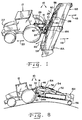
- is a side view of the mower of Fig. 1 with the cutter heads folded to a transport position;
- Fig. 4
- is a perspective view illustrating a hitch assembly and cantilever beams;
- Fig. 5
- is a fragmentary, perspective view of the hitch assembly and of the cantilever beams shown in Fig. 4;
- Fig. 6
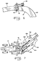
- is a fragmentary, side view of the hitch assembly and one of the cantilever beams shown in Figs. 4 and 5;
- Fig. 7
- is a top view of the mower shown in Figs. 1-3, with the cutter heads in a transport position and pivoted relative to the hitch assembly; and
- Fig. 8
- is a side view of the mower shown in Figs. 1-3 and 7, with the cutter heads folded to the transport position and traversing over uneven ground.
- Corresponding reference characters indicate corresponding parts throughout the several views. The exemplification set out herein illustrates one preferred embodiment of the invention, in one form, and such exemplification is not to be construed as limiting the scope of the invention in any manner.
- Referring now to the drawings, and more particularly to Figs. 1-3, there is shown an embodiment of an agricultural working
unit 10 of the present invention, in the form of a mower.Mower 10 generally includes or is attached to atraction unit 12, hashitch assembly 14, pair ofworking heads cantilever beams -
Traction unit 12 may be of any type suitable for a given application, and preferably in the embodiment shown, is in the form of a bi-directional traction unit, as indicated by double headeddirectional arrow 20. Configured as such, an operator may face in either direction with suitable seating, operating controls, etc. so that either longitudinal direction can be considered a "forward" direction. - Alternatively,
traction unit 12 can be configured as a typical agricultural tractor with the forward end beingadjacent hood 22 which houses an internal combustion engine. Configured as such, the front end oftraction unit 12 may optionally be provided with a 3-point hitch attachment (not shown), such thathitch assembly 14 may be coupled with either the forward or the rearward end oftraction unit 12. -
Hitch assembly 14 is in the form of a 3-point hitch assembly which is coupled withtraction unit 12 using two lower lift arms orlinks 24 and atop link 26.Lower lift arms 24 andtop link 26 are typically thought of as being part oftraction unit 12, thus allowingtraction unit 12 to be detachably coupled withhitch assembly 14. -
Lower lift arms 24 are preferably separate from each other and hydraulically operated from withintraction unit 12 and raise andlower hitch assembly 14 in alifting direction 28. Of course, it will be appreciated that liftingdirection 28 has a somewhat curved profile as liftarms 24 pivot about the pivotal couplings withtraction unit 12. For simplicity sakes, however,lifting direction 28 is assumed to be generally linear at least over a short lifting distance. In any event, the lifting mechanism will permit thelift arms 24 to float during operation and coupled between thetraction unit 12 and the lift arms are respective hydraulic float cylinders (not shown) that are coupled to an accumulator (not shown) so as to provide a lifting action on thehitch assembly 14 to counterbalance the weight of thecutter heads lower lift arms 24 is disclosed in U.S. Patent No. 5,983,615, granted 16 November 1999, and assigned to the applicant of this application. -
Top link 26 is an axially adjustable top link such as a hydraulic cylinder which may be actuated from within the cab oftraction unit 12.Hydraulic cylinder 26 may be placed in a "float" position which opens the oil on opposite sides of the piston withinhydraulic cylinder 26 to allow the hydraulic ram to float freely from a retracted to an extended position, as indicated by directional arrow 30 (Figs. 3 and 8). This is accomplished by placing a hydraulic lever within the cab oftraction unit 12 in a "float" position. Of course, whenhydraulic cylinder 26 is not in the float position, the ram is fixed at an axial position selected by the user. The extension or retraction of the ram ofhydraulic cylinder 26 adjusts the cutting orientation ofcutter head - Working
heads cutter head cutterbar 32 for cutting the vegetative matter.Cutterbar 32 is in the form of a rotating disk cutterbar in the embodiment shown, but may also be in the form of a sickle cutterbar (not shown).Cutterbar 32 includes a plurality ofcutterbar modules 34, each having a generally oblong shaped disk with a pair of knives respectively positioned at the longitudinal ends of the disk.Cutterbar modules 34 associated with eachcutter head proximal cutterbar module 34A positioned closest to hitchassembly 14 and adistal cutterbar module 34B positioned furthest fromhitch assembly 14 each carry a convergingdrum 36 thereabove for directing flow of the vegetative matter toward the center of eachcutter head -
Proximal cutterbar modules 34A receive input power from a common input power source and serially drive the remainingcutterbar modules 34. In particular, eachproximal cutterbar module 34A is coupled with agear box 38 via a respectivetelescoping power shaft 40.Gear box 38 is mounted to hitch assembly 14 (as indicated schematically byline 39 in Figs. 2 and 3) and coupled with a power source ontraction unit 12 via telescoping power take-offshaft 42, but may alternatively be coupled to an output shaft of a hydraulic motor (not shown) mounted adjacent the gear box and driven by a pump located ontraction unit 12. In another non-shown embodiment hydraulic motors may be connected to respective ends of eachcutter head Traction unit 12 thereby positively drivesproximal cutterbar modules 34A in a timed manner relative to each other such thatproximal cutterbar modules 34A overlap but do not interfere with each other during operation. This ensures that the vegetative matter is cut without any gaps or spaces extending from the distal end of onecutter head 16A to the distal end of theother cutter head 16B. - Each
cutter head - Cantilever beams 18A and 18B extend in a cantilever manner from
hitch assembly 14. More particularly, eachbeam assembly 14 which is pivotally connected withhitch assembly 14 about arespective pivot axis 44 which extends generally parallel to lifting direction 28 (see, e.g., Figs. 2 and 3). -
Beams assembly 14 using an adjustable linkage arrangement in the form of ahydraulic cylinder 46. The adjustable linkage arrangement oradjustment arrangement 46 may be configured other than a hydraulic cylinder, depending upon the particular application, and in fact may include a separate adjusting device for eachbeam hydraulic cylinder 46causes beams beams traction unit 12 being reversed for transport, thebeams heads hitch assembly 14. Retraction ofhydraulic cylinder 46causes beams cutter head - Each
beam assembly 14 which is pivotally connected with arespective cutter head cutter head mower 10 during operation. Eachcutter head pivot axis 50 at the distal end of eachcorresponding beam pivot axis 50 extends generally parallel with workingdirection 48. In the embodiment shown, eachpivot axis 50 is positioned approximately midway between the proximal end and distal end of eachcorresponding cutter head respective cutter head - To further assist in balancing cutter heads 16A and 16B, a hydraulic balancing arrangement including a pair of
hydraulic cylinders 52 coupled in parallel with each other and apreload spring 54 apply a selected lifting force to the distal end of eachcutter head hydraulic cylinder 52 usingspring 54 adjusts the lifting force applied to the distal end of arespective cutter head hydraulic cylinder 52. - Each
cutter head transport wheel 56.Transport wheel 56 may be removable or retractable, and is aligned generally parallel with the running direction oftraction unit 12 when cutter heads 16A and 16B are in the transport position (Figs. 3 and 8).Transport wheel 56 functions to support the distal end of eachcutter head beams - Cutter heads 16A and 16B each include a forming
shield 58 which is configured, in a conventional manner, not shown in detail, for adjusting both swath width as well as swath location. Preferably, each formingshield 58 is configured to selectively deflect cut crop to form a wide swath beginning just outside the wheel track of the adjacent wheel of the traction unit 12 (wide swaths being preferred when more drying of the crop is desired), or to deflect the cut crop more toward the distal end of eachrespective cutter head directional arrows 60 in Fig. 1, and in this way form a narrower swath of crop. In this manner, the wheels oftraction unit 12 do not straddle a swath cut bycutter heads cutter head traction unit 12 is reversed at the end of a field and moved across the field in an opposite direction. For example, iftraction unit 12 is moved in working direction 48 (Fig. 1) and then reversed in a clockwise direction at the end of the field and moved in a working direction opposite to that shown, the two swaths fromcutter head 16A will lie closely adjacent to each other and away fromtraction unit 12. The width of the adjacent swaths fromcutter head 16A are also preferably adjusted so that the combined width of the two swaths may be picked up by a single pickup head of a, forage chopper or the like. - Referring now to Figs. 4-6,
hitch assembly 14 andbeams Hitch assembly 14 includes an arched frame defined by atop cross arm 61 and a pair ofcurved legs 63 extending downwardly and transversely away fromtop cross arm 61. Instead of twolegs 63 one leg could be used which at its bottom extends transversely to thelower links 24.Hitch assembly 14 includes a pair oflower couplings 62 which couple withlower lift arms 24; and anupper coupling 64 which couples withtop link 26.Hydraulic cylinder 46pivots beams top cross arm 61 between a working position (shown in Figs. 1 and 2) and a transport position (shown in Figs. 3-5 and 7-8).Hydraulic cylinder 46 maintainsbeams traction unit 12 is positioned either in line or offset frombeams hydraulic cylinder 46 is slightly offset from a line extending throughaxes 44 to create a momentum of thebeams beams hydraulic cylinder 46 assumes this offset position. This offset is hardly visible in figure 1. -
Hitch assembly 14 includes a pair ofstops 66 for limiting pivotal movement ofbeams Stops 66 are in the form of projections which extend fromhitch assembly 14 with respective abutment surfaces 68 which define mechanical limits for limiting pivoting action ofbeams corresponding beam beam respective beam beams - In the embodiment shown, stops 66 are formed as part of
hitch assembly 14. It is to be understood, however, that the stops for limiting pivotal movement of cutter heads 16A and 16B relative to hitchassembly 14 may be formed onhitch assembly 14 and/orbeams - During use, cutter heads 16A and 16B are unfolded to the working position shown in Fig. 1 using
hydraulic cylinder 46. By attaching cutter heads 16A and 16B at the upper portion ofarched hitch assembly 14 and positioning cutter heads 16A and 16B generally in line with each other when in the working position, cutter heads 16A and 16B are able to be placed closer totraction unit 12 during use.Hydraulic cylinder 26 may be extended or retracted to adjust the tilt of cutter heads 16A and 16B. Liftarms 24 oftraction unit 12 are positioned such that cutter heads 16A and 16B are at a desired distance above the ground.Power shaft 42 is engaged, which in turn drivesgearbox 38,power shafts 40, andcutterbars 32. Cutter heads 16A and 16B are moved across the field in workingdirection 48 usingtraction unit 12. The vegetative matter is cut bycutterbars 32, conditioned by the conditioner for better drying, and discharged from formingshields 58 for forming wide swaths generally directly behind the cutter heads when accelerated drying is desired, or selectively for forming swaths centered toward the distal ends of therespective cutter head - To prepare for transport, beams 18A and 18B are pivoted to the transport position shown in Figs. 3, 7 and 8 by extending the ram within
hydraulic cylinder 46. The axial stroke length ofhydraulic cylinder 46 may be set such thatbeams hydraulic cylinder 46 is in the extended position.Transport wheels 56 are either attached to or lowered from a corresponding cutter head to support the distal ends thereof. The ram inhydraulic cylinder 52 betweencutter head respective beam transport wheels 56. - During transport,
hydraulic cylinder 46 maintains cutter heads 16A and 16B in a generally parallel relationship with each other, while at the same time allowing cutter heads 16A and 16B to shift in a longitudinal direction relative to each other during turning maneuvers or the like (Fig. 7).Hydraulic cylinder 26 defining the top link of the 3-point hitch attachment is placed in the float mode allowing the ram thereof to extend and retract freely. Thus, astraction unit 12 and cutter heads 16A and 16B traverse over uneven ground, 3-point hitch assembly 14 is supported bylower lift arms 24 but free to pivot relative to traction unit 12 (compare Figs. 3 and 8). - The extent to which cutter heads 16A and 16B may pivot relative to hitch
assembly 14 is limited by stops 66.
Claims (13)
- Mower (10), comprising:a) a hitch assembly (14) including a top cross arm (61) and at least one leg (63) extending downwardly and transversely away from said top cross arm (61);b) a pair of cutter heads (16A, 16B), each including a cutterbar (32), in particular comprising rotary cutting discs;c) a pair of cantilever beams (18A, 18B), each being connected at one end with said hitch assembly (14) for pivoting horizontally about an upright axis (44), and at an other end with a respective said cutter head (16A, 16B) for establishing a horizontal axis about which said respective cutter head (16A, 16B) may pivot vertically.
- Mower according to claim 1, characterized in that said beams (18A, 18B) are pivotally connected with said hitch assembly (14) such that said cutter heads (16A, 16B) are movable between a transport position in which said cutter heads (16A, 16B) are generally parallel with each other, and a working position in which said cutter heads (16A, 16B) are generally longitudinally aligned with each other.
- Mower according to claim 1 or 2, characterized by an adjustment arrangement (46) in particular a hydraulic cylinder, for moving said cutter heads (16A, 16B) between said transport position and said working position.
- Mower according to one or more of the preceding claims, characterized in that each said beam (18A, 18B) is pivotally connected to a respective said cutter head (16A, 16B) approximately midway between a proximal end and a distal end relative to said hitch assembly (14).
- Mower according to one or more of the preceding claims, characterized in that at least one cutter head (16A, 16B) can be equipped with at least one transport wheel (56) at said distal end.
- Mower according to one or more of the preceding claims, characterized by a gear box (38), coupled to each of said cutterbars (34) by means of telescoping power shafts (40).
- Mower according to one or more of the preceding claims 1 to 5, characterized in that the cutter heads (16A, 16B) are driven by means of hydraulic motors directly or via a gear box (38).
- Mower according to one or more of the preceding claims, characterized in that each said cutter bar (34) has a proximal cutter bar module (34A) closest to said hitch assembly (14), said proximal cutter bar modules (34A) being timed relative to each other, preferably by using said gear box (38).
- Mower according to one or more of the preceding claims, characterized in that each said cutter bar (34) has a proximal cutter bar module (34A) closest to said hitch assembly (14), said proximal cutter bar modules (34A) being configured to overlap but not interfere with each other during operation.
- Mower according to one or more of the preceding claims, characterized in that each said cutter head (16A, 16B) includes a forming shield (58) configured for adjusting both swath width and swath location.
- Mower according to one or more of the preceding claims, characterized in that the hitch assembly (14) can be coupled to a three point hitch comprising lower and/or upper links (24) and/or (26) being moveable hydraulically and/or being able to assume a float mode.
- Mower according to one or more of the preceding claims, characterized by at least one stop (66) being associated with said beams (18A, 18B) for limiting pivotal movement of said beams (18A, 18B) relative to said hitch assembly (14).
- Mower according to one or more of the preceding claims, characterized in that said stops (66) comprise mechanical limits on said hitch assembly (14) and include an abutment surface (68) engaging a corresponding said beam (18A, 18B) when said beam (18A, 18B) is at a predetermined position, whereas said abutment surface (68) is preferably generally parallel to said corresponding beam (18A, 18B) when said beam (18A, 18B) is at said predetermined position.
Applications Claiming Priority (2)
| Application Number | Priority Date | Filing Date | Title |
|---|---|---|---|
| US10/154,044 US6837033B2 (en) | 2002-05-23 | 2002-05-23 | Agricultural bi-mower with cantilever beam suspension |
| US154044 | 2002-05-23 |
Publications (2)
| Publication Number | Publication Date |
|---|---|
| EP1364569A1 true EP1364569A1 (en) | 2003-11-26 |
| EP1364569B1 EP1364569B1 (en) | 2006-11-15 |
Family
ID=29400545
Family Applications (1)
| Application Number | Title | Priority Date | Filing Date |
|---|---|---|---|
| EP03011285A Expired - Lifetime EP1364569B1 (en) | 2002-05-23 | 2003-05-17 | Mower |
Country Status (6)
| Country | Link |
|---|---|
| US (3) | US6837033B2 (en) |
| EP (1) | EP1364569B1 (en) |
| AT (1) | ATE345030T1 (en) |
| CA (1) | CA2429091C (en) |
| DE (1) | DE60309623T2 (en) |
| ES (1) | ES2272837T3 (en) |
Cited By (4)
| Publication number | Priority date | Publication date | Assignee | Title |
|---|---|---|---|---|
| FR2871077A1 (en) * | 2004-06-02 | 2005-12-09 | Gyrax Soc Par Actions Simplifi | Grinder mill for use with tractor, has spring hooked between arm and stopper unit for brining arm against stopper, such that crushing modules move between folded back storage position and deployed working position |
| ES2291092A1 (en) * | 2005-09-30 | 2008-02-16 | Jose Serrat Alcay | DEVELOPING MACHINE. |
| EP2666350A3 (en) * | 2012-05-25 | 2015-04-15 | Alois Pöttinger Maschinenfabrik Ges. m.b.H. | Mower |
| ES3008096A1 (en) * | 2023-09-21 | 2025-03-21 | Stirmot S L | Flotation system for a windrower rake attached to a baler (Machine-translation by Google Translate, not legally binding) |
Families Citing this family (36)
| Publication number | Priority date | Publication date | Assignee | Title |
|---|---|---|---|---|
| FR2836775B1 (en) * | 2002-03-11 | 2004-07-16 | Kuhn Sa | AGRICULTURAL MACHINE FOR BEING ATTACHED TO A HITCH BAR OF A TRACTOR VEHICLE |
| FR2853492B1 (en) * | 2003-04-11 | 2006-02-17 | Kuhn Sa | AGRICULTURAL MOWER FOR MAINTAINING AN OVERLAPPING OF SUCCESSIVE WORKING AREAS DURING WORK IN DEVERS |
| US7210538B2 (en) * | 2004-03-27 | 2007-05-01 | Cnh America Llc | Center pivot wing flotation method and apparatus |
| DE102005040174A1 (en) * | 2005-08-25 | 2007-03-15 | Deere & Company, Moline | Agricultural press |
| GB0613348D0 (en) * | 2006-07-05 | 2006-08-16 | Parsons Janette S | Reflective breeching |
| US7726109B2 (en) | 2007-10-30 | 2010-06-01 | Vermeer Manufacturing Co. | Four-bar linkage for suspending a header for an agricultural implement |
| US20090107100A1 (en) * | 2007-10-30 | 2009-04-30 | Bollinger Shane A | Cushioned swing cylinder for agricultural mower |
| US7596935B2 (en) * | 2007-10-30 | 2009-10-06 | Vermeer Manufacturing Company | Suspension system for a floating header on an agricultural implement |
| US7658056B2 (en) * | 2007-10-30 | 2010-02-09 | Vermeer Manufacturing Co. | System for folding an agricultural machine with a floating work tool |
| US7784255B2 (en) * | 2007-11-15 | 2010-08-31 | Bush Hog Inc. | Rotary cutters |
| GB0723993D0 (en) * | 2007-12-08 | 2008-01-16 | Agco Sa | Implement control system |
| US8464508B2 (en) | 2009-07-31 | 2013-06-18 | Agco Corporation | Biomass baler |
| US8443580B2 (en) | 2009-07-31 | 2013-05-21 | Agco Corporation | Baler pickup for collecting biomass from a combine harvester |
| US8490375B2 (en) | 2009-07-31 | 2013-07-23 | Agco Corporation | Baler collector for collecting biomass from a combine harvester |
| US20110023436A1 (en) * | 2009-07-31 | 2011-02-03 | Agco Corporation | Baler Tongue for Collecting Biomass |
| US8261521B2 (en) * | 2009-08-31 | 2012-09-11 | Vermeer Manufacturing Company | Self-leveling four-bar linkage for suspending a header of an agricultural implement |
| US8056307B2 (en) * | 2009-10-05 | 2011-11-15 | Cnh America Llc | Mower cutterbar |
| US7913797B1 (en) | 2009-12-01 | 2011-03-29 | Brad Mohns | Bi-directional utility vehicle |
| US8528308B2 (en) * | 2010-01-19 | 2013-09-10 | Cnh America, Llc | Disc mower with folding wing frame |
| FR2974270B1 (en) * | 2011-04-21 | 2014-04-04 | Kuhn Sa | AGRICULTURAL MACHINE WITH AN IMPROVED FOLDING DEVICE |
| US8769920B2 (en) * | 2011-11-16 | 2014-07-08 | Macdon Industries Ltd. | Header transport for a crop harvesting machine |
| US8418777B1 (en) * | 2011-12-09 | 2013-04-16 | GK Machine, Inc. | Agricultural folding scraper blade |
| US20140223878A1 (en) * | 2013-02-08 | 2014-08-14 | Robert Sassone | Lawn Mower Assemblies |
| US8713904B1 (en) | 2013-03-15 | 2014-05-06 | Harlan Clifford Goudy | Mower for cutting around or near obstacles |
| CA2932816A1 (en) | 2016-06-14 | 2017-12-14 | Degelman Industries Ltd. | Land roller |
| TWI688042B (en) * | 2016-07-05 | 2020-03-11 | 聯華電子股份有限公司 | Method of fabricating semiconductor device |
| US10165726B2 (en) * | 2016-12-23 | 2019-01-01 | Cnh Industrial America Llc | Agricultural header with multiple knife drives |
| US10085373B2 (en) | 2017-01-28 | 2018-10-02 | Neal Nuss | Harvester combine header assembly |
| JP7611697B2 (en) * | 2017-07-26 | 2025-01-10 | クバンランド グループ ケアデミネ エーエス | Electric disc grass cutter |
| CN110651586A (en) * | 2018-06-30 | 2020-01-07 | 湖北智权专利技术应用开发有限公司 | Flexible shaft transmission all-terrain remote control mower |
| NL2021519B1 (en) * | 2018-08-30 | 2020-04-24 | Ploeger Oxbo Europe B V | Self-propelled agricultural machine, for example a self-propelled belt rake |
| CN109566590B (en) * | 2018-12-24 | 2025-03-25 | 重庆远贝科技有限公司 | A lawn mower |
| CN110207971B (en) * | 2019-06-28 | 2024-07-12 | 华南农业大学 | A field agricultural machinery test hook-up trolley with balancing and fine-tuning functions |
| CN112578777A (en) * | 2019-09-27 | 2021-03-30 | 苏州宝时得电动工具有限公司 | Autonomous robot and walking path planning method and device thereof and storage medium |
| US12102039B1 (en) * | 2020-11-30 | 2024-10-01 | Alamo Group Inc. | Variable offset hitch and related work machines |
| DE102023108337A1 (en) * | 2023-03-31 | 2024-10-02 | Claas Saulgau Gmbh | agricultural implement |
Citations (5)
| Publication number | Priority date | Publication date | Assignee | Title |
|---|---|---|---|---|
| FR1094356A (en) * | 1953-11-03 | 1955-05-20 | Improvements to mechanical mowers | |
| DE1582350A1 (en) * | 1967-03-31 | 1971-07-15 | Hans Grenzebach | Mowing device with rotating cutting tools |
| EP0514314A1 (en) * | 1991-04-25 | 1992-11-19 | Jf-Fabriken - J. Freudendahl A/S | Tractor suspension for a lift suspended agricultural implement, especially a disc mower or a cylinder mower |
| WO1995001715A1 (en) * | 1993-07-07 | 1995-01-19 | Hcs (Ireland) Limited | A mower |
| EP0756813A1 (en) * | 1994-08-05 | 1997-02-05 | Max Hölzle | Rotary mower |
Family Cites Families (28)
| Publication number | Priority date | Publication date | Assignee | Title |
|---|---|---|---|---|
| US3003789A (en) * | 1960-03-11 | 1961-10-10 | Calkins Mfg Company | Universal hillside hydraulic hitch |
| US3526083A (en) * | 1967-12-19 | 1970-09-01 | Robert O Barry | Post mower |
| US3791115A (en) * | 1972-07-06 | 1974-02-12 | Deere & Co | Tractor-mounted mower |
| US3893283A (en) * | 1974-06-20 | 1975-07-08 | John E Dandl | Variable width earth surface treating apparatus |
| US4135349A (en) * | 1977-02-25 | 1979-01-23 | Schwertner Larry V | Crop shredder apparatus and adapter |
| US4183195A (en) * | 1978-08-22 | 1980-01-15 | Terrain King Corporation | Mounting apparatus for offset mower |
| US4262921A (en) * | 1979-03-21 | 1981-04-21 | Dwyer Thomas L | Tandem implement hitch |
| CA1141177A (en) * | 1980-10-17 | 1983-02-15 | William T. Arnold | Gang mower with single cylinder lifting mechanism |
| DE3134389A1 (en) * | 1981-08-31 | 1983-03-10 | Klöckner-Humboldt-Deutz AG Zweigniederlassung Fahr, 7702 Gottmadingen | MOWER |
| US4552224A (en) * | 1984-03-19 | 1985-11-12 | Terry Luscombe | Hitch assembly for a tandem disc implement |
| FR2584889B1 (en) * | 1985-07-18 | 1989-05-05 | Kuhn Sa | MOWER WITH LOADING MECHANISM |
| US4697404A (en) * | 1985-10-01 | 1987-10-06 | Brockmeier Sod Farms | Tractor mower system |
| FR2635433B1 (en) * | 1988-08-18 | 1991-02-01 | Kuhn Sa | IMPROVED CHASSIS MOWER |
| US5069022A (en) * | 1990-09-28 | 1991-12-03 | Befco, Inc. | Gang mower apparatus |
| US5133174A (en) * | 1991-01-28 | 1992-07-28 | Parsons Jr Ralph L | Hydraulically driven mowing unit |
| FR2687039B1 (en) * | 1992-02-12 | 1994-04-29 | Kuhn Sa | MOWER WITH IMPROVED LOCKING DEVICE. |
| DK171218B1 (en) | 1992-02-28 | 1996-08-05 | Freudendahl J Fab As | Lawn mower mower |
| FR2719189B1 (en) * | 1994-04-29 | 1996-07-05 | Kuhn Sa | Mower with safety device. |
| FR2726152B1 (en) * | 1994-10-28 | 1997-01-24 | Kuhn Sa | AGRICULTURAL MACHINE FOR CUTTING PLANTS WITH IMPROVED PROTECTION DEVICE |
| NL1003292C2 (en) * | 1996-06-07 | 1997-12-10 | Maasland Nv | Hay construction machine. |
| FR2763473B1 (en) * | 1997-05-26 | 1999-07-23 | Kuhn Sa | DEVICE FOR MODIFYING THE POSITION OF AN AGRICULTURAL MACHINE HITCHED BY A THREE-POINT HITCH |
| US5949436A (en) * | 1997-09-30 | 1999-09-07 | Compaq Computer Corporation | Accelerated graphics port multiple entry gart cache allocation system and method |
| US6021506A (en) * | 1998-07-31 | 2000-02-01 | Intel Corporation | Method and apparatus for stopping a bus clock while there are no activities on a bus |
| US6346946B1 (en) * | 1998-10-23 | 2002-02-12 | Micron Technology, Inc. | Graphics controller embedded in a core logic unit |
| US6302220B1 (en) * | 1999-10-28 | 2001-10-16 | Flexi-Coil Ltd. | Agricultural ground working implement with hydraulic downpressure circuit |
| US5983615A (en) * | 1998-11-03 | 1999-11-16 | Deere & Company | Windrower platform side-to-side float balance adjustment |
| US6326973B1 (en) * | 1998-12-07 | 2001-12-04 | Compaq Computer Corporation | Method and system for allocating AGP/GART memory from the local AGP memory controller in a highly parallel system architecture (HPSA) |
| DE10121014A1 (en) * | 2001-04-28 | 2002-11-21 | Deere & Co | mowing |
-
2002
- 2002-05-23 US US10/154,044 patent/US6837033B2/en not_active Expired - Lifetime
-
2003
- 2003-05-17 EP EP03011285A patent/EP1364569B1/en not_active Expired - Lifetime
- 2003-05-17 ES ES03011285T patent/ES2272837T3/en not_active Expired - Lifetime
- 2003-05-17 DE DE60309623T patent/DE60309623T2/en not_active Expired - Lifetime
- 2003-05-17 AT AT03011285T patent/ATE345030T1/en not_active IP Right Cessation
- 2003-05-20 CA CA002429091A patent/CA2429091C/en not_active Expired - Fee Related
-
2004
- 2004-10-05 US US10/959,834 patent/US7024844B2/en not_active Expired - Lifetime
- 2004-10-05 US US10/958,939 patent/US7051501B2/en not_active Expired - Lifetime
Patent Citations (5)
| Publication number | Priority date | Publication date | Assignee | Title |
|---|---|---|---|---|
| FR1094356A (en) * | 1953-11-03 | 1955-05-20 | Improvements to mechanical mowers | |
| DE1582350A1 (en) * | 1967-03-31 | 1971-07-15 | Hans Grenzebach | Mowing device with rotating cutting tools |
| EP0514314A1 (en) * | 1991-04-25 | 1992-11-19 | Jf-Fabriken - J. Freudendahl A/S | Tractor suspension for a lift suspended agricultural implement, especially a disc mower or a cylinder mower |
| WO1995001715A1 (en) * | 1993-07-07 | 1995-01-19 | Hcs (Ireland) Limited | A mower |
| EP0756813A1 (en) * | 1994-08-05 | 1997-02-05 | Max Hölzle | Rotary mower |
Cited By (6)
| Publication number | Priority date | Publication date | Assignee | Title |
|---|---|---|---|---|
| FR2871077A1 (en) * | 2004-06-02 | 2005-12-09 | Gyrax Soc Par Actions Simplifi | Grinder mill for use with tractor, has spring hooked between arm and stopper unit for brining arm against stopper, such that crushing modules move between folded back storage position and deployed working position |
| ES2291092A1 (en) * | 2005-09-30 | 2008-02-16 | Jose Serrat Alcay | DEVELOPING MACHINE. |
| ES2291092B1 (en) * | 2005-09-30 | 2009-01-16 | Jose Serrat Alcay | DEVELOPING MACHINE. |
| EP2666350A3 (en) * | 2012-05-25 | 2015-04-15 | Alois Pöttinger Maschinenfabrik Ges. m.b.H. | Mower |
| ES3008096A1 (en) * | 2023-09-21 | 2025-03-21 | Stirmot S L | Flotation system for a windrower rake attached to a baler (Machine-translation by Google Translate, not legally binding) |
| EP4527173A1 (en) | 2023-09-21 | 2025-03-26 | Stirmot, S.L. | Flotation system for swathing rake attachable to a baler |
Also Published As
| Publication number | Publication date |
|---|---|
| DE60309623T2 (en) | 2007-09-13 |
| ES2272837T3 (en) | 2007-05-01 |
| DE60309623D1 (en) | 2006-12-28 |
| US7051501B2 (en) | 2006-05-30 |
| CA2429091A1 (en) | 2003-11-23 |
| ATE345030T1 (en) | 2006-12-15 |
| US6837033B2 (en) | 2005-01-04 |
| EP1364569B1 (en) | 2006-11-15 |
| US20050044831A1 (en) | 2005-03-03 |
| CA2429091C (en) | 2007-10-23 |
| US7024844B2 (en) | 2006-04-11 |
| US20050044832A1 (en) | 2005-03-03 |
| US20030217537A1 (en) | 2003-11-27 |
Similar Documents
| Publication | Publication Date | Title |
|---|---|---|
| EP1364569B1 (en) | Mower | |
| EP3272199B1 (en) | Mulching device for processing plant stumps on a field | |
| US7404283B2 (en) | Crop collecting assembly for an agricultural harvester | |
| US6109012A (en) | Hay-making machine | |
| US6907719B2 (en) | Agricultural implement comprising a transporting device | |
| US4135349A (en) | Crop shredder apparatus and adapter | |
| US6658828B2 (en) | Mowing implement including mowing units connected to carrier frame exclusive of windrowing device | |
| EP3269223B1 (en) | Harvesting attachment with a mulching device | |
| US3841070A (en) | Windrow placement device and harvesting method | |
| US12171160B2 (en) | Flex wing mower | |
| CA2323988C (en) | Self-propelled agricultural vehicle | |
| CA2323948C (en) | Mowing implement | |
| US20020152735A1 (en) | Haymaking machine, particularly a mower with a windrow grouping device | |
| EP0558437A1 (en) | Mower for grass crops | |
| CA1318137C (en) | Swather attachment for bi-directional tractor | |
| EP1616474B1 (en) | A towed mower comprising a running frame and two mowing aggregates | |
| US20080168755A1 (en) | Harvesting Implement, Particularly Front Harvesting Attachment For Agricultural Harvesting Machines For Taking Up Cereal Crops and Conveying It Further | |
| US7712295B2 (en) | Agricultural machine comprising a motor vehicle and several working units intended to cut plant products | |
| CA2323978C (en) | Vehicle | |
| RU2028035C1 (en) | Agricultural harvesting aggregate | |
| WO2014059379A1 (en) | Tractor on top cotton harvester with sightline to picker unit below the tractor | |
| WO2014059380A1 (en) | Tractor on top cotton harvester with rear picker unit lift and tilt mechanism | |
| GB2231249A (en) | Flail mower | |
| JPH10150821A (en) | Horizontal moving device for harvesting such as combine harvesters | |
| DE6606472U (en) | FIELD HARVESTERS. |
Legal Events
| Date | Code | Title | Description |
|---|---|---|---|
| PUAI | Public reference made under article 153(3) epc to a published international application that has entered the european phase |
Free format text: ORIGINAL CODE: 0009012 |
|
| AK | Designated contracting states |
Kind code of ref document: A1 Designated state(s): AT BE BG CH CY CZ DE DK EE ES FI FR GB GR HU IE IT LI LU MC NL PT RO SE SI SK TR |
|
| AX | Request for extension of the european patent |
Extension state: AL LT LV MK |
|
| 17P | Request for examination filed |
Effective date: 20040526 |
|
| AKX | Designation fees paid |
Designated state(s): AT BE BG CH CY CZ DE DK EE ES FI FR GB GR HU IE IT LI LU MC NL PT RO SE SI SK TR |
|
| GRAP | Despatch of communication of intention to grant a patent |
Free format text: ORIGINAL CODE: EPIDOSNIGR1 |
|
| GRAS | Grant fee paid |
Free format text: ORIGINAL CODE: EPIDOSNIGR3 |
|
| GRAA | (expected) grant |
Free format text: ORIGINAL CODE: 0009210 |
|
| AK | Designated contracting states |
Kind code of ref document: B1 Designated state(s): AT BE BG CH CY CZ DE DK EE ES FI FR GB GR HU IE IT LI LU MC NL PT RO SE SI SK TR |
|
| PG25 | Lapsed in a contracting state [announced via postgrant information from national office to epo] |
Ref country code: RO Free format text: LAPSE BECAUSE OF FAILURE TO SUBMIT A TRANSLATION OF THE DESCRIPTION OR TO PAY THE FEE WITHIN THE PRESCRIBED TIME-LIMIT Effective date: 20061115 Ref country code: BE Free format text: LAPSE BECAUSE OF FAILURE TO SUBMIT A TRANSLATION OF THE DESCRIPTION OR TO PAY THE FEE WITHIN THE PRESCRIBED TIME-LIMIT Effective date: 20061115 Ref country code: FI Free format text: LAPSE BECAUSE OF FAILURE TO SUBMIT A TRANSLATION OF THE DESCRIPTION OR TO PAY THE FEE WITHIN THE PRESCRIBED TIME-LIMIT Effective date: 20061115 Ref country code: CZ Free format text: LAPSE BECAUSE OF FAILURE TO SUBMIT A TRANSLATION OF THE DESCRIPTION OR TO PAY THE FEE WITHIN THE PRESCRIBED TIME-LIMIT Effective date: 20061115 Ref country code: SI Free format text: LAPSE BECAUSE OF FAILURE TO SUBMIT A TRANSLATION OF THE DESCRIPTION OR TO PAY THE FEE WITHIN THE PRESCRIBED TIME-LIMIT Effective date: 20061115 Ref country code: CH Free format text: LAPSE BECAUSE OF FAILURE TO SUBMIT A TRANSLATION OF THE DESCRIPTION OR TO PAY THE FEE WITHIN THE PRESCRIBED TIME-LIMIT Effective date: 20061115 Ref country code: LI Free format text: LAPSE BECAUSE OF FAILURE TO SUBMIT A TRANSLATION OF THE DESCRIPTION OR TO PAY THE FEE WITHIN THE PRESCRIBED TIME-LIMIT Effective date: 20061115 Ref country code: NL Free format text: LAPSE BECAUSE OF FAILURE TO SUBMIT A TRANSLATION OF THE DESCRIPTION OR TO PAY THE FEE WITHIN THE PRESCRIBED TIME-LIMIT Effective date: 20061115 Ref country code: SK Free format text: LAPSE BECAUSE OF FAILURE TO SUBMIT A TRANSLATION OF THE DESCRIPTION OR TO PAY THE FEE WITHIN THE PRESCRIBED TIME-LIMIT Effective date: 20061115 Ref country code: AT Free format text: LAPSE BECAUSE OF FAILURE TO SUBMIT A TRANSLATION OF THE DESCRIPTION OR TO PAY THE FEE WITHIN THE PRESCRIBED TIME-LIMIT Effective date: 20061115 |
|
| REG | Reference to a national code |
Ref country code: GB Ref legal event code: FG4D |
|
| REG | Reference to a national code |
Ref country code: CH Ref legal event code: EP |
|
| REF | Corresponds to: |
Ref document number: 60309623 Country of ref document: DE Date of ref document: 20061228 Kind code of ref document: P |
|
| REG | Reference to a national code |
Ref country code: IE Ref legal event code: FG4D |
|
| PG25 | Lapsed in a contracting state [announced via postgrant information from national office to epo] |
Ref country code: BG Free format text: LAPSE BECAUSE OF FAILURE TO SUBMIT A TRANSLATION OF THE DESCRIPTION OR TO PAY THE FEE WITHIN THE PRESCRIBED TIME-LIMIT Effective date: 20070215 Ref country code: DK Free format text: LAPSE BECAUSE OF FAILURE TO SUBMIT A TRANSLATION OF THE DESCRIPTION OR TO PAY THE FEE WITHIN THE PRESCRIBED TIME-LIMIT Effective date: 20070215 Ref country code: SE Free format text: LAPSE BECAUSE OF FAILURE TO SUBMIT A TRANSLATION OF THE DESCRIPTION OR TO PAY THE FEE WITHIN THE PRESCRIBED TIME-LIMIT Effective date: 20070215 |
|
| PG25 | Lapsed in a contracting state [announced via postgrant information from national office to epo] |
Ref country code: PT Free format text: LAPSE BECAUSE OF FAILURE TO SUBMIT A TRANSLATION OF THE DESCRIPTION OR TO PAY THE FEE WITHIN THE PRESCRIBED TIME-LIMIT Effective date: 20070416 |
|
| NLV1 | Nl: lapsed or annulled due to failure to fulfill the requirements of art. 29p and 29m of the patents act | ||
| REG | Reference to a national code |
Ref country code: ES Ref legal event code: FG2A Ref document number: 2272837 Country of ref document: ES Kind code of ref document: T3 |
|
| ET | Fr: translation filed | ||
| REG | Reference to a national code |
Ref country code: CH Ref legal event code: PL |
|
| PLBE | No opposition filed within time limit |
Free format text: ORIGINAL CODE: 0009261 |
|
| STAA | Information on the status of an ep patent application or granted ep patent |
Free format text: STATUS: NO OPPOSITION FILED WITHIN TIME LIMIT |
|
| 26N | No opposition filed |
Effective date: 20070817 |
|
| PG25 | Lapsed in a contracting state [announced via postgrant information from national office to epo] |
Ref country code: MC Free format text: LAPSE BECAUSE OF NON-PAYMENT OF DUE FEES Effective date: 20070531 |
|
| PG25 | Lapsed in a contracting state [announced via postgrant information from national office to epo] |
Ref country code: GR Free format text: LAPSE BECAUSE OF FAILURE TO SUBMIT A TRANSLATION OF THE DESCRIPTION OR TO PAY THE FEE WITHIN THE PRESCRIBED TIME-LIMIT Effective date: 20070216 |
|
| PG25 | Lapsed in a contracting state [announced via postgrant information from national office to epo] |
Ref country code: IE Free format text: LAPSE BECAUSE OF NON-PAYMENT OF DUE FEES Effective date: 20070517 |
|
| PGFP | Annual fee paid to national office [announced via postgrant information from national office to epo] |
Ref country code: ES Payment date: 20080526 Year of fee payment: 6 |
|
| PG25 | Lapsed in a contracting state [announced via postgrant information from national office to epo] |
Ref country code: EE Free format text: LAPSE BECAUSE OF FAILURE TO SUBMIT A TRANSLATION OF THE DESCRIPTION OR TO PAY THE FEE WITHIN THE PRESCRIBED TIME-LIMIT Effective date: 20061115 |
|
| PG25 | Lapsed in a contracting state [announced via postgrant information from national office to epo] |
Ref country code: CY Free format text: LAPSE BECAUSE OF FAILURE TO SUBMIT A TRANSLATION OF THE DESCRIPTION OR TO PAY THE FEE WITHIN THE PRESCRIBED TIME-LIMIT Effective date: 20061115 Ref country code: LU Free format text: LAPSE BECAUSE OF NON-PAYMENT OF DUE FEES Effective date: 20070517 |
|
| PG25 | Lapsed in a contracting state [announced via postgrant information from national office to epo] |
Ref country code: TR Free format text: LAPSE BECAUSE OF FAILURE TO SUBMIT A TRANSLATION OF THE DESCRIPTION OR TO PAY THE FEE WITHIN THE PRESCRIBED TIME-LIMIT Effective date: 20061115 Ref country code: HU Free format text: LAPSE BECAUSE OF FAILURE TO SUBMIT A TRANSLATION OF THE DESCRIPTION OR TO PAY THE FEE WITHIN THE PRESCRIBED TIME-LIMIT Effective date: 20070516 |
|
| REG | Reference to a national code |
Ref country code: ES Ref legal event code: FD2A Effective date: 20090518 |
|
| PG25 | Lapsed in a contracting state [announced via postgrant information from national office to epo] |
Ref country code: ES Free format text: LAPSE BECAUSE OF NON-PAYMENT OF DUE FEES Effective date: 20090518 |
|
| REG | Reference to a national code |
Ref country code: FR Ref legal event code: PLFP Year of fee payment: 14 |
|
| PGFP | Annual fee paid to national office [announced via postgrant information from national office to epo] |
Ref country code: IT Payment date: 20160520 Year of fee payment: 14 |
|
| REG | Reference to a national code |
Ref country code: FR Ref legal event code: PLFP Year of fee payment: 15 |
|
| PGFP | Annual fee paid to national office [announced via postgrant information from national office to epo] |
Ref country code: FR Payment date: 20170525 Year of fee payment: 15 Ref country code: GB Payment date: 20170530 Year of fee payment: 15 |
|
| PG25 | Lapsed in a contracting state [announced via postgrant information from national office to epo] |
Ref country code: IT Free format text: LAPSE BECAUSE OF NON-PAYMENT OF DUE FEES Effective date: 20170517 |
|
| GBPC | Gb: european patent ceased through non-payment of renewal fee |
Effective date: 20180517 |
|
| PG25 | Lapsed in a contracting state [announced via postgrant information from national office to epo] |
Ref country code: GB Free format text: LAPSE BECAUSE OF NON-PAYMENT OF DUE FEES Effective date: 20180517 Ref country code: FR Free format text: LAPSE BECAUSE OF NON-PAYMENT OF DUE FEES Effective date: 20180531 |
|
| PGFP | Annual fee paid to national office [announced via postgrant information from national office to epo] |
Ref country code: DE Payment date: 20190423 Year of fee payment: 17 |
|
| REG | Reference to a national code |
Ref country code: DE Ref legal event code: R119 Ref document number: 60309623 Country of ref document: DE |
|
| PG25 | Lapsed in a contracting state [announced via postgrant information from national office to epo] |
Ref country code: DE Free format text: LAPSE BECAUSE OF NON-PAYMENT OF DUE FEES Effective date: 20201201 |