EP1364157B1 - Luminaire - Google Patents
Luminaire Download PDFInfo
- Publication number
- EP1364157B1 EP1364157B1 EP02710252A EP02710252A EP1364157B1 EP 1364157 B1 EP1364157 B1 EP 1364157B1 EP 02710252 A EP02710252 A EP 02710252A EP 02710252 A EP02710252 A EP 02710252A EP 1364157 B1 EP1364157 B1 EP 1364157B1
- Authority
- EP
- European Patent Office
- Prior art keywords
- reflector
- luminaire
- lamp
- symmetry
- plane
- Prior art date
- Legal status (The legal status is an assumption and is not a legal conclusion. Google has not performed a legal analysis and makes no representation as to the accuracy of the status listed.)
- Expired - Lifetime
Links
- 238000012216 screening Methods 0.000 claims description 12
- 238000005286 illumination Methods 0.000 abstract description 6
- 238000009826 distribution Methods 0.000 description 15
- 230000004907 flux Effects 0.000 description 7
- 230000002349 favourable effect Effects 0.000 description 4
- 238000010586 diagram Methods 0.000 description 3
- 239000000463 material Substances 0.000 description 3
- 229910052782 aluminium Inorganic materials 0.000 description 2
- XAGFODPZIPBFFR-UHFFFAOYSA-N aluminium Chemical compound [Al] XAGFODPZIPBFFR-UHFFFAOYSA-N 0.000 description 2
- 239000000725 suspension Substances 0.000 description 2
- 238000009434 installation Methods 0.000 description 1
- 230000031700 light absorption Effects 0.000 description 1
- 238000012423 maintenance Methods 0.000 description 1
- 238000004519 manufacturing process Methods 0.000 description 1
- 238000005259 measurement Methods 0.000 description 1
- 229910052751 metal Inorganic materials 0.000 description 1
- 239000002184 metal Substances 0.000 description 1
- 230000005855 radiation Effects 0.000 description 1
- 239000007858 starting material Substances 0.000 description 1
- 229920003002 synthetic resin Polymers 0.000 description 1
- 239000000057 synthetic resin Substances 0.000 description 1
- 230000007704 transition Effects 0.000 description 1
Images

Classifications
-
- F—MECHANICAL ENGINEERING; LIGHTING; HEATING; WEAPONS; BLASTING
- F21—LIGHTING
- F21V—FUNCTIONAL FEATURES OR DETAILS OF LIGHTING DEVICES OR SYSTEMS THEREOF; STRUCTURAL COMBINATIONS OF LIGHTING DEVICES WITH OTHER ARTICLES, NOT OTHERWISE PROVIDED FOR
- F21V7/00—Reflectors for light sources
- F21V7/04—Optical design
- F21V7/09—Optical design with a combination of different curvatures
-
- F—MECHANICAL ENGINEERING; LIGHTING; HEATING; WEAPONS; BLASTING
- F21—LIGHTING
- F21V—FUNCTIONAL FEATURES OR DETAILS OF LIGHTING DEVICES OR SYSTEMS THEREOF; STRUCTURAL COMBINATIONS OF LIGHTING DEVICES WITH OTHER ARTICLES, NOT OTHERWISE PROVIDED FOR
- F21V7/00—Reflectors for light sources
- F21V7/005—Reflectors for light sources with an elongated shape to cooperate with linear light sources
-
- F—MECHANICAL ENGINEERING; LIGHTING; HEATING; WEAPONS; BLASTING
- F21—LIGHTING
- F21V—FUNCTIONAL FEATURES OR DETAILS OF LIGHTING DEVICES OR SYSTEMS THEREOF; STRUCTURAL COMBINATIONS OF LIGHTING DEVICES WITH OTHER ARTICLES, NOT OTHERWISE PROVIDED FOR
- F21V7/00—Reflectors for light sources
- F21V7/04—Optical design
-
- F—MECHANICAL ENGINEERING; LIGHTING; HEATING; WEAPONS; BLASTING
- F21—LIGHTING
- F21Y—INDEXING SCHEME ASSOCIATED WITH SUBCLASSES F21K, F21L, F21S and F21V, RELATING TO THE FORM OR THE KIND OF THE LIGHT SOURCES OR OF THE COLOUR OF THE LIGHT EMITTED
- F21Y2103/00—Elongate light sources, e.g. fluorescent tubes
-
- F—MECHANICAL ENGINEERING; LIGHTING; HEATING; WEAPONS; BLASTING
- F21—LIGHTING
- F21Y—INDEXING SCHEME ASSOCIATED WITH SUBCLASSES F21K, F21L, F21S and F21V, RELATING TO THE FORM OR THE KIND OF THE LIGHT SOURCES OR OF THE COLOUR OF THE LIGHT EMITTED
- F21Y2113/00—Combination of light sources
Landscapes
- Engineering & Computer Science (AREA)
- General Engineering & Computer Science (AREA)
- Non-Portable Lighting Devices Or Systems Thereof (AREA)
- Vessels And Coating Films For Discharge Lamps (AREA)
Abstract
Description
- The invention relates to a luminaire comprising:
- a hollow reflector having
- a plane of symmetry,
- a light emission window extending transversely to the plane of symmetry,
- reflector side portions on either side of the plane of symmetry; and
- means, in the plane of symmetry, for accommodating a tubular electric lamp along the light emission window, which means define a position of an axis of the lamp to be accommodated, in the plane of symmetry,
- Such a luminaire is disclosed in
AT-B-386 671 - The known luminaire is intended for use in rooms where display screens are employed.
- Therefore, such luminaires are designed such that they do not, or hardly, emit light sideways at an angle of, for example, at least 25° with the light emission window, i.e. the so-termed screening angle, in order to make sure that annoying reflections on display screens are avoided. To achieve this, the lamp is arranged so high in the reflector that said lamp is invisible from the screening angle and hence does not emit light in said screening angle. Customarily, such luminaires comprise a concave, for example parabolically curved reflector, which is formed such that also light reflected by the reflector, which light intersects the plane of symmetry of the reflector, is not emitted within the screening angle.
- It has been found that small errors in the manufacture of the reflector can lead to deviant shapes, as a result of which parts of the reflector situated near the light emission window do emit light within said screening angle.
- In order to increase the permissible variation in shape, and hence preclude this undesirable reflection within the screening angle, the known luminaire in accordance with said
AT-B-386 671 - A drawback of the known luminaire resides in that it produces a comparatively narrow-angle beam, i.e. a beam with a comparatively high luminous flux on the axis and a comparatively rapid reduction of the luminous flux at comparatively small angles with the axis, and in that, if a plurality of luminaires are necessary to illuminate a comparatively large room, the luminaires must be comparatively closely spaced in order to obtain a uniform illumination. As a result, the installation and maintenance costs of the lighting are high.
-
US-A-4,403,275 discloses a luminaire comprising a box-shaped housing without a reflector, which luminaire is designed so as to accommodate four juxtaposed, tubular lamps. A smaller luminous flux is obtained by omitting the outermost lamps from said luminaire. Light generated by the innermost lamps may be lost in corners of the housing. This loss is limited by incorporating a screen that is S-shaped in cross-section in the lamp holders intended for the outermost lamps. This luminaire emits light at a very small angle with the light emission window and hence cannot suitably be used in rooms where display screens are employed. - It is an object of the invention to provide a luminaire of the type described in the opening paragraph, which, while the emission of light in the screening angle is precluded, emits light in a uniform manner, also if use is made of a plurality of similar luminaires arranged at comparatively large distances from each other.
- In accordance with the invention, this object is achieved in that the distance from the line of inflection points to the light emission window is 0.30 to 0.40 of the distance from the outer edge to the axis of the lamp to be accommodated.
- As the line of inflection points is situated comparatively close to the light emission window, the light emission of the luminaire in accordance with the invention, after reflection of the light by a zone situated around the line of inflection points, is such that comparatively much light is sent far away, through the plane of symmetry, at a comparatively small angle with the light emission window. The line of inflection points of the reflector known from said
AT-B-386 671 - As a result of the wider spread of the light, which will be shown in the drawings, luminaires in accordance with the invention can be arranged comparatively far apart to obtain a uniform illumination.
- The luminaire in accordance with the invention has the advantage that it has a comparatively high flexibility, enabling identical reflector side portions of the reflector to be positioned such that the outer edges are situated at varying distances from each other. As a result, said distance can be adapted to the measurements of modular ceiling systems if the luminaire must be incorporated therein. For example, said distance can be varied between, for example, 125 and 140 mm. By changing the distance between the outer edges, the distance from the outer edge to the axis of the lamp to be accommodated changes too, which axis is defined by the means for accommodating a lamp. Thus, while using an identical reflector side portion, also the position of the line of inflection points changes with respect to the light emission window, expressed as a fraction of the distance from the outer edge to the lamp axis.
- The second area is formed, near its inner edge, so as to send the light reflected by it substantially through the plane of symmetry. The light reflected at said location enlarges the luminous flux in directions enclosing an angle with the plane of symmetry, which is not the case in the known luminaire, where light reflected at this location issues to the exterior perpendicularly through the light emission window to contribute to the center of the beam. A uniform illumination is thus obtained at even larger intervals between the luminaires.
It is favorable for the second area to be shaped, near its inner edge, such that reflection at the lamp to be accommodated is at least substantially avoided. By virtue thereof, the disturbance of the beam path and loss of light by light absorption by the lamp are precluded. - For the same reason, the first area is formed such that light reflected by it near the outer edge can be reflected, on the same side of the plane of symmetry, in directions aside. In the known luminaire, at this location the light is emitted to the exterior at right angles to the light emission window so as to contribute to the center of the beam.
- The luminaire comprises a concave area that extends as far as the inner edge, the second area has a flat zone along the inner edge. By the flat, essentially noncurved zone, comparatively much light is sent obliquely through the plane of symmetry and the light emission window to the exterior, so that, at a uniform or substantially uniform light distribution in the beam, it is possible to employ reflector side portions having a smaller surface area of the second portion. As a result, a saving in material costs can be realized. A further advantage resides in that the reflector side portions can be readily manufactured by roll forming.
- The luminaire may comprise a second, substantially identical reflector with second means for accommodating a second lamp, with means for operating the lamps to be accommodated being present between the reflector and the second reflector. A particularly favorable property of the luminaire in accordance with the invention is that, as a result of the shape of the reflector side portions, which shape is also determined by the location of the line of inflection points, there is enough space between the two juxtaposed reflector side portions of a twin or multiple luminaire to accommodate, for example, a ballast or an electronic starter for discharge lamps to be accommodated. As a result, the depth of the luminaire can be reduced, so that less material is necessary and, if the luminaire is to be mounted in a floating ceiling, a smaller space between said floating ceiling and the actual ceiling is sufficient.
- The luminaire can be suspended from a ceiling. Said luminaire may be open on the upper side so as to also emit indirect light, or it may be closed. On the other hand, the luminaire may be mounted to or in a ceiling. If desired, the light emission window may be provided with lamellae extending transversely to the plane of symmetry, which lamellae serve to also create a screening angle in the longitudinal direction of the luminaire. The lamellae may be flat or three-dimensional, for example with hollow, such as parabolically curved, side faces. The side faces of flat lamellae may be provided with a relief pattern of, for example, sawtooth-shaped strips, to reflect incident light in a downward direction.
- The reflector and, if present, the lamellae may be of a synthetic resin or of a metal, such as aluminum. They may be polish finished, semipolish finished or matt finished. They may alternatively be made of a lacquered material.
- The lamellae may have parallel edges in the light emission window and, for example, straight edges within the reflector or, in a suitable case, they may have a concave edge in the light emission window and a convex edge within the reflector. Alternatively, both edges may be convex.
- It is favorable for the reflector to be accommodated in a housing which is, for example, diffusely reflecting. In this case, an opening between the inner edges of the reflector is covered, opposite the light emission window, by the housing. And radiation which is diffusely reflected by the housing is uniformly added to the light beam.
- The luminaire in accordance with the invention can particularly suitably be used to accommodate a fluorescent lamp having a diameter of, for example, approximately 26 or approximately 16 mm.
- Embodiments of the luminaire in accordance with the invention are shown in the drawing.
- In the drawing:
-
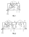
Fig. 1 is a cross-sectional view of a first embodiment; -
Fig. 2 is a cross-sectional view of a second embodiment; -
Fig. 3 shows the light intensity distribution diagram obtained by means of the luminaire shown inFig. 1 ; -
Fig. 4 shows the light intensity distribution diagram obtained by means of the known luminaire. - The luminaire shown in
Fig. 1 has ahollow reflector 1 with a plane ofsymmetry 2. Alight emission window 3 extends transversely to the plane ofsymmetry 2. Thereflector 1 comprisesreflector side portions 10 on either side of the plane ofsymmetry 2. The luminaire comprises means 20 in the plane ofsymmetry 2 enabling a tubular electric lamp L to be accommodated along thelight emission window 3. Said means define a position of anaxis 21 of the lamp L to be accommodated in the plane ofsymmetry 2. The means shown in the Figure are a pair of lamp holders, one of which is visible and the other extends in line therewith in front of the plane of the drawing, said pair of lamp holders being suitable to accommodate a linear fluorescent lamp. - The
reflector side portions 10 each comprise afirst area 11, which has anouter edge 12 in thelight emission window 3 and extends, as a convex area, away from the light emission window, and a second,concave area 13 which joins the first,convex area 11 in a straight line of inflection points 14. The second area has aninner edge 15 near theaxis 21 of the lamp L to be accommodated. The line ofinflection points 14 is situated at a distance from thelight emission window 3. Thereflector side portions 10 yield a lateral screening angle α of at least 25°, and 30° in the Figure shown. - The distance from the line of
inflection points 14 to thelight emission window 3 is 0.30 to 0.40 of the distance from theouter edges 12 to theaxis 21 of the lamp L to be accommodated. - Near its
inner edge 15, thesecond area 13 is formed so as to send the light reflected by said area substantially through the plane ofsymmetry 2. In the Figure, the rays reflected at the edge itself are shown, which rays originate from the upper side of the lamp L, the lower side, the center and from two intermediate locations. This shows that one ray, originating from the upper side of the lamp L, is reflected substantially parallel to the plane ofsymmetry 2, while the other rays intersect the plane ofsymmetry 2. - Even in the case of reflection at the
inner wall 15 itself, reflection to the lamp L is precluded at least substantially. - The
first area 11 is formed such that light reflected by it near theouter edge 12 is reflected, on the same side of the plane ofsymmetry 2, in directions aside. In the Figure, two outermost rays originating, as a result of reflection at theouter edge 12, from rays originating from the upper side and the lower side of the lamp L, as well as a ray which, as a result of reflection, originates from a ray originating from the center of the lamp L. The Figure shows that one ray, originating from the lower side of the lamp L, is reflected in a direction substantially parallel to the plane of symmetry, while the other rays are caused to diverge in directions aside the luminaire. - The reflector is accommodated in a
housing 30 which is diffusely reflecting. - The line of
inflection points 14 is at a distance of approximately 31 mm from thelight emission window 3. As regards the luminaire in accordance with the invention shown inFig. 1 , where theouter edges 12 are at a distance of 125 mm from each other, theaxis 21 of the lamp L is situated at a distance of 84 mm from theouter edges 12, and hence the distance of the line ofinflection points 14 is 0.37 of the distance from the axis to the outer edge. At a distance between theouter edges 12 of 140 mm, the distance from theaxis 21 to theouter edges 12 is 90 mm. As a result, the distance of the line ofinflection points 14 is 0.34 of the distance from the axis to the outer edge. - In
Fig. 2 , corresponding parts are indicated by means of the same reference numeral as inFig. 1 . InFig. 2 , thesecond area 13 has aflat zone 16 along theinner edge 15. Thiszone 16 can be used very effectively to laterally reflect light through the plane ofsymmetry 2. By virtue thereof, a smaller dimension of thereflector side portions 10 inFig. 2 is sufficient to create a beam distribution which is substantially identical to that shown inFig. 1 . - The luminaire shown in
Fig. 2 is a twin luminaire comprising a second, substantially identical reflector 1' and second means 20' for accommodating a second lamp L', with means 22 for operating the lamps L, L' to be accommodated being present between thereflector 1 and the second reflector 1'. Said means 22 comprise, in the embodiment shown, two ballasts or, in a variant, a twin ballast. - A comparison between
Fig. 1 and Fig. 2 shows that the specific convex/concave shape of thereflector side portions 10 of the luminaire in accordance with the invention enables, in a multiple luminaire, to accommodate means 22 in thehousing 30 between two neighboringreflector side portions 10, while said means 22 could not be accommodated in an equallyhigh housing 30, as shown inFig. 1 , for lack of space. - In
Fig. 2 , the line ofinflection points 14 is situated at a distance of approximately 30 mm from thelight emission window 3. In the case of the luminaire according to the invention, as shown inFig. 2 , where theouter edges 12 are situated at a distance of 125 mm from each other, theaxis 21 of the lamp L is situated at a distance of 84 mm from theouter edges 12 and, consequently, the distance of the line ofinflection points 14 is 0.36 of the distance from the axis to the outer edges. If the distance between theouter edges 12 is 140 mm, then the distance from theaxis 21 to theouter edges 12 is 90 mm. Thus, the distance of the line ofinflection points 14 is 0.33 of the distance from the axis to the outer edge. - The diagram shown in
Fig. 3 shows the light intensity distribution in a plane at right angles to the plane ofsymmetry 2. The line 0.0-180.0 coincides with the plane ofsymmetry 2, the line 90.0-90.0- is situated in the light emission window. As is customary, the light intensity distribution is converted to that obtained at a luminous flux of 1000 lm. As a result, the light intensity distributions of different luminaires comprising different lamps can be directly compared with each other. - The light intensity distributions shown in
Figs. 3 and 4 relate to, respectively, the luminaire in accordance with the invention and the known luminaire provided with an aluminum high-gloss reflector having a reflection coefficient of 0.85 in a lacquered housing with a reflection coefficient of 0.88. - A comparison of the light intensity distribution of
Fig. 3 with the light intensity distribution ofFig. 4 , which belongs to the known luminaire mentioned in the opening paragraph, reveals that both luminaires do not, or hardly, emit light between 60° and 90° in both directions and hence have a screening angle α of 30°. It has further been found that the light intensity distribution shown inFig. 4 has maximum values at 10°, whereasFig. 3 has maximum values in the range from approximately 30° to approximately 35°. It is favorable that the luminous intensity at angles in the range from 30° to 35° is higher than at an angle of 0°, because, if a surface extending parallel to the light emission window is illuminated, then, at larger angles, said surface is at a larger distance than at smaller angles and hence the beam must emit more light in said direction to obtain an equal illumination intensity.Fig. 3 shows that, at angles above 35°, still a considerable luminous flux is emitted as compared to the maximum values, whereas, inFig. 3 , the luminous flux at said angles is negligible as compared to the maximum values. The light intensity distribution shown inFig. 3 is delta-shaped, while the light intensity distribution shown inFig. 4 is drop-shaped. In comparison with the known luminaire, the luminaire in accordance with the invention has a more uniform light distribution over a larger field and enables luminaires to be arranged at a larger distance from each other to uniformly illuminate a very large field. - The light intensity distribution of the luminaire shown in
Fig. 2 is substantially equal to that shown inFig. 3 . - If a plurality of luminaires in accordance with the invention are suspended in a square grid, the grid size may be maximally 1.7 times the height of suspension to make sure that uniform illumination is maintained. As regards the known luminaire, the grid size may maximally amount to 1.4 times the height of suspension.
Claims (4)
- A luminaire comprising:- a hollow reflector (1) having- a plane of symmetry (2),- a light emission window (3) extending transversely to the plane of symmetry (2),- reflector side portions (10) on either side of the plane of symmetry (2); and- means (20), in the plane of symmetry (2), for accommodating a tubular electric lamp (L) along the light emission window (3), which means define a position of an axis (21) of the lamp (L) to be accommodated in the plane of symmetry (2),which reflector side portions (10) each include a first, convex area (11) with an outer edge (12) in the light emission window (3), and a second concave area (13) which connects to the first, convex area (11) in a line of inflection points (14), and which has an inner edge (15) close to the axis (21) of the lamp (L) to be accommodated, the line of inflection points (14) being situated at a distance from the light emission window (3), and the reflector side portions (10) forming a lateral screening angle a of at least 25°,
characterized in that the distance from the line of inflection points (14) to the light emission window (3) is 0.30 to 0.40 of the distance from the outer edge (12) to the axis (21) of the lamp (L) to be accommodated,
that the first area (11) is formed such that light reflected by it near the outer edge (12) can be reflected, on the same side of the plane of symmetry (2), in directions aside,
that the second area (13) is formed, near its inner edge (15), so as to send the light reflected by it substantially through the plane of symmetry (2), and
that the second area (13) comprises a flat zone (16) along the inner edge (15). - A luminaire as claimed in claim 1, characterized in that the second area (13) is formed, near its inner edge (15), so as to send light reflected by it through the plane of symmetry (2) and, thus, at least substantially avoid reflection at the lamp (L) to be accommodated.
- A luminaire as claimed in claim 1 or 2, characterized in that a second, substantially identical reflector (1') and second means (20') for accommodating a second 10 lamp (L') are present, with means (22) being present between the reflector (1) and the second reflector (1') for operating the lamps (L, L') to be accommodated.
- A luminaire as claimed in claim 1 or 2, characterized in that the reflector is accommodated in a housing (30) which is diffusely reflecting.
Priority Applications (1)
| Application Number | Priority Date | Filing Date | Title |
|---|---|---|---|
| EP02710252A EP1364157B1 (en) | 2001-02-23 | 2002-02-08 | Luminaire |
Applications Claiming Priority (4)
| Application Number | Priority Date | Filing Date | Title |
|---|---|---|---|
| EP01200664 | 2001-02-23 | ||
| EP01200664 | 2001-02-23 | ||
| EP02710252A EP1364157B1 (en) | 2001-02-23 | 2002-02-08 | Luminaire |
| PCT/IB2002/000410 WO2002066891A1 (en) | 2001-02-23 | 2002-02-08 | Luminaire |
Publications (2)
| Publication Number | Publication Date |
|---|---|
| EP1364157A1 EP1364157A1 (en) | 2003-11-26 |
| EP1364157B1 true EP1364157B1 (en) | 2010-05-19 |
Family
ID=8179925
Family Applications (1)
| Application Number | Title | Priority Date | Filing Date |
|---|---|---|---|
| EP02710252A Expired - Lifetime EP1364157B1 (en) | 2001-02-23 | 2002-02-08 | Luminaire |
Country Status (8)
| Country | Link |
|---|---|
| US (1) | US6578983B2 (en) |
| EP (1) | EP1364157B1 (en) |
| JP (1) | JP4030431B2 (en) |
| CN (1) | CN1201112C (en) |
| AT (1) | ATE468511T1 (en) |
| DE (1) | DE60236409D1 (en) |
| ES (1) | ES2345538T3 (en) |
| WO (1) | WO2002066891A1 (en) |
Families Citing this family (22)
| Publication number | Priority date | Publication date | Assignee | Title |
|---|---|---|---|---|
| JP3994896B2 (en) * | 2002-09-25 | 2007-10-24 | コニカミノルタホールディングス株式会社 | Video display device |
| EP1712833A4 (en) * | 2004-02-04 | 2009-06-03 | Nitto Denko Corp | Lighting device and light irradiating device using it and production method for photoreaction product sheet using those devices |
| USD538462S1 (en) | 2004-04-19 | 2007-03-13 | Orion Energy Systems Ltd. | Fluorescent tube light low bay reflector |
| FR2909024B1 (en) * | 2006-11-23 | 2009-02-13 | Cogema | GLOVE BOX WITH SPRINKLE SEATED ENCLOSURE |
| US8206009B2 (en) * | 2007-09-19 | 2012-06-26 | Cooper Technologies Company | Light emitting diode lamp source |
| US7874700B2 (en) | 2007-09-19 | 2011-01-25 | Cooper Technologies Company | Heat management for a light fixture with an adjustable optical distribution |
| WO2009039491A1 (en) * | 2007-09-21 | 2009-03-26 | Cooper Technologies Company | Light emitting diode recessed light fixture |
| JP5396703B2 (en) * | 2007-10-09 | 2014-01-22 | 富士通セミコンダクター株式会社 | Heat treatment apparatus and method, and semiconductor device manufacturing method |
| US7883236B2 (en) * | 2008-02-07 | 2011-02-08 | Lsi Industries, Inc. | Light fixture and reflector assembly for same |
| US7887216B2 (en) | 2008-03-10 | 2011-02-15 | Cooper Technologies Company | LED-based lighting system and method |
| US8123382B2 (en) | 2008-10-10 | 2012-02-28 | Cooper Technologies Company | Modular extruded heat sink |
| US20100208460A1 (en) * | 2009-02-19 | 2010-08-19 | Cooper Technologies Company | Luminaire with led illumination core |
| WO2011004297A1 (en) * | 2009-07-08 | 2011-01-13 | Koninklijke Philips Electronics N.V. | An illumination device |
| WO2011011323A1 (en) | 2009-07-21 | 2011-01-27 | Cooper Technologies Company | Interfacing a light emitting diode (led) module to a heat sink assembly, a light reflector and electrical circuits |
| US8596837B1 (en) | 2009-07-21 | 2013-12-03 | Cooper Technologies Company | Systems, methods, and devices providing a quick-release mechanism for a modular LED light engine |
| US20110032698A1 (en) * | 2009-08-05 | 2011-02-10 | U.R. Tech Corporation | United reflection lights with light-emitting diode |
| JP5990768B2 (en) * | 2012-04-19 | 2016-09-14 | パナソニックIpマネジメント株式会社 | Strobe device |
| RU2563226C1 (en) * | 2014-07-29 | 2015-09-20 | Олег Леонидович Ступников | Lighting fixture |
| CN104456423A (en) * | 2014-10-20 | 2015-03-25 | 深圳市极成光电有限公司 | Anti-dazzle reflective cup |
| DE102015108499A1 (en) * | 2015-05-29 | 2016-12-01 | Osram Opto Semiconductors Gmbh | Optoelectronic component with a radiation source |
| US10795238B2 (en) * | 2018-12-06 | 2020-10-06 | Microsoft Technology Licensing, Llc | Light reflection |
| US11204152B2 (en) * | 2019-08-15 | 2021-12-21 | Microsoft Technology Licensing, Llc | Illumination device having reflector with concave and convex symmetrical surfaces |
Family Cites Families (7)
| Publication number | Priority date | Publication date | Assignee | Title |
|---|---|---|---|---|
| US4403275A (en) | 1981-03-16 | 1983-09-06 | Fao, Inc. | Wattless lamp assembly |
| DE8315374U1 (en) * | 1983-05-25 | 1983-11-24 | Skoglund, Christer, Basingstoke, Hants | REFLECTOR ASSEMBLY FOR FLUORESCENT TUBES |
| AT386671B (en) | 1986-03-24 | 1988-09-26 | Zumtobel Ag | LAMP WITH A LAMP AND WITH A REFLECTOR |
| US4719546A (en) * | 1986-05-21 | 1988-01-12 | Spitz Russell W | Fluorescent lighting apparatus |
| US4888668A (en) * | 1987-09-28 | 1989-12-19 | Siemens Aktiengesellschaft | Mirror light unit |
| US5988836A (en) * | 1996-07-31 | 1999-11-23 | Swarens; Ralph W. | Recessed indirect fluorescent light fixture with flexible reflector |
| EP1030997A1 (en) * | 1998-07-23 | 2000-08-30 | Koninklijke Philips Electronics N.V. | Luminaire |
-
2002
- 2002-02-08 WO PCT/IB2002/000410 patent/WO2002066891A1/en active Application Filing
- 2002-02-08 DE DE60236409T patent/DE60236409D1/en not_active Expired - Lifetime
- 2002-02-08 AT AT02710252T patent/ATE468511T1/en active
- 2002-02-08 CN CNB02800387XA patent/CN1201112C/en not_active Expired - Fee Related
- 2002-02-08 EP EP02710252A patent/EP1364157B1/en not_active Expired - Lifetime
- 2002-02-08 JP JP2002566171A patent/JP4030431B2/en not_active Expired - Fee Related
- 2002-02-08 ES ES02710252T patent/ES2345538T3/en not_active Expired - Lifetime
- 2002-02-21 US US10/081,962 patent/US6578983B2/en not_active Expired - Lifetime
Also Published As
| Publication number | Publication date |
|---|---|
| JP4030431B2 (en) | 2008-01-09 |
| WO2002066891A1 (en) | 2002-08-29 |
| DE60236409D1 (en) | 2010-07-01 |
| JP2004519815A (en) | 2004-07-02 |
| CN1457415A (en) | 2003-11-19 |
| ATE468511T1 (en) | 2010-06-15 |
| CN1201112C (en) | 2005-05-11 |
| ES2345538T3 (en) | 2010-09-27 |
| US6578983B2 (en) | 2003-06-17 |
| EP1364157A1 (en) | 2003-11-26 |
| US20020141182A1 (en) | 2002-10-03 |
Similar Documents
| Publication | Publication Date | Title |
|---|---|---|
| EP1364157B1 (en) | Luminaire | |
| US6457844B2 (en) | Light distributor for a lighting device and lighting device and use of a lighting device | |
| US5251116A (en) | Luminaire for creating a primary beam and a secondary beam | |
| US4229782A (en) | High efficiency lighting units with beam cut-off angle | |
| US4564888A (en) | Wall-wash lighting fixture | |
| US4344111A (en) | High efficiency lighting units and systems using same | |
| US20070047235A1 (en) | Method and apparatus for providing light | |
| JPS61284003A (en) | Indirectly reflective lighting fixture | |
| US20070047233A1 (en) | Method and apparatus for providing light | |
| CA2180712C (en) | Lighting fixture having a parabolic louver | |
| EP0643258B1 (en) | Luminaire | |
| US3786248A (en) | Luminaire | |
| CA2175554C (en) | Indirect asymmetric luminaire assembly | |
| US20070047236A1 (en) | Method and apparatus for providing light | |
| US6250780B1 (en) | Indoor luminaire assembly | |
| FI66482B (en) | LAONGSTRAECKT ARBETSPLATSBELYSNINGSARMATUR | |
| US7246924B2 (en) | High performance lighting louvers and luminaires | |
| US7281824B2 (en) | Luminaire with reflector having two portions with different optical axes | |
| US20070047234A1 (en) | Method and apparatus for providing light | |
| EP1472491B1 (en) | Luminaire with lamellas, for tubular lamp | |
| US4364105A (en) | Stacked fixtures with angularly positioned lamps and downwardly light-directing reflectors | |
| EP0564022B1 (en) | A lighting fixture | |
| KR101259539B1 (en) | Bug controlled lamp with light reflector direccional for localized road | |
| JPH0230004A (en) | Luminaire and system luminaire | |
| EP0260478A2 (en) | Wall mounted luminaire |
Legal Events
| Date | Code | Title | Description |
|---|---|---|---|
| PUAI | Public reference made under article 153(3) epc to a published international application that has entered the european phase |
Free format text: ORIGINAL CODE: 0009012 |
|
| 17P | Request for examination filed |
Effective date: 20030923 |
|
| AK | Designated contracting states |
Kind code of ref document: A1 Designated state(s): AT BE CH CY DE DK ES FI FR GB GR IE IT LI LU MC NL PT SE TR |
|
| 17Q | First examination report despatched |
Effective date: 20070419 |
|
| GRAP | Despatch of communication of intention to grant a patent |
Free format text: ORIGINAL CODE: EPIDOSNIGR1 |
|
| GRAS | Grant fee paid |
Free format text: ORIGINAL CODE: EPIDOSNIGR3 |
|
| GRAA | (expected) grant |
Free format text: ORIGINAL CODE: 0009210 |
|
| AK | Designated contracting states |
Kind code of ref document: B1 Designated state(s): AT BE CH CY DE DK ES FI FR GB GR IE IT LI LU MC NL PT SE TR |
|
| REG | Reference to a national code |
Ref country code: GB Ref legal event code: FG4D |
|
| REG | Reference to a national code |
Ref country code: CH Ref legal event code: EP |
|
| REG | Reference to a national code |
Ref country code: IE Ref legal event code: FG4D |
|
| REF | Corresponds to: |
Ref document number: 60236409 Country of ref document: DE Date of ref document: 20100701 Kind code of ref document: P |
|
| REG | Reference to a national code |
Ref country code: NL Ref legal event code: T3 |
|
| REG | Reference to a national code |
Ref country code: ES Ref legal event code: FG2A Ref document number: 2345538 Country of ref document: ES Kind code of ref document: T3 |
|
| PG25 | Lapsed in a contracting state [announced via postgrant information from national office to epo] |
Ref country code: SE Free format text: LAPSE BECAUSE OF FAILURE TO SUBMIT A TRANSLATION OF THE DESCRIPTION OR TO PAY THE FEE WITHIN THE PRESCRIBED TIME-LIMIT Effective date: 20100519 |
|
| PG25 | Lapsed in a contracting state [announced via postgrant information from national office to epo] |
Ref country code: FI Free format text: LAPSE BECAUSE OF FAILURE TO SUBMIT A TRANSLATION OF THE DESCRIPTION OR TO PAY THE FEE WITHIN THE PRESCRIBED TIME-LIMIT Effective date: 20100519 |
|
| PG25 | Lapsed in a contracting state [announced via postgrant information from national office to epo] |
Ref country code: CY Free format text: LAPSE BECAUSE OF FAILURE TO SUBMIT A TRANSLATION OF THE DESCRIPTION OR TO PAY THE FEE WITHIN THE PRESCRIBED TIME-LIMIT Effective date: 20100519 Ref country code: GR Free format text: LAPSE BECAUSE OF FAILURE TO SUBMIT A TRANSLATION OF THE DESCRIPTION OR TO PAY THE FEE WITHIN THE PRESCRIBED TIME-LIMIT Effective date: 20100820 |
|
| PG25 | Lapsed in a contracting state [announced via postgrant information from national office to epo] |
Ref country code: DK Free format text: LAPSE BECAUSE OF FAILURE TO SUBMIT A TRANSLATION OF THE DESCRIPTION OR TO PAY THE FEE WITHIN THE PRESCRIBED TIME-LIMIT Effective date: 20100519 Ref country code: PT Free format text: LAPSE BECAUSE OF FAILURE TO SUBMIT A TRANSLATION OF THE DESCRIPTION OR TO PAY THE FEE WITHIN THE PRESCRIBED TIME-LIMIT Effective date: 20100920 |
|
| PG25 | Lapsed in a contracting state [announced via postgrant information from national office to epo] |
Ref country code: BE Free format text: LAPSE BECAUSE OF FAILURE TO SUBMIT A TRANSLATION OF THE DESCRIPTION OR TO PAY THE FEE WITHIN THE PRESCRIBED TIME-LIMIT Effective date: 20100519 |
|
| PLBE | No opposition filed within time limit |
Free format text: ORIGINAL CODE: 0009261 |
|
| STAA | Information on the status of an ep patent application or granted ep patent |
Free format text: STATUS: NO OPPOSITION FILED WITHIN TIME LIMIT |
|
| 26N | No opposition filed |
Effective date: 20110222 |
|
| REG | Reference to a national code |
Ref country code: DE Ref legal event code: R097 Ref document number: 60236409 Country of ref document: DE Effective date: 20110221 |
|
| PG25 | Lapsed in a contracting state [announced via postgrant information from national office to epo] |
Ref country code: MC Free format text: LAPSE BECAUSE OF NON-PAYMENT OF DUE FEES Effective date: 20110228 |
|
| REG | Reference to a national code |
Ref country code: CH Ref legal event code: PL |
|
| PG25 | Lapsed in a contracting state [announced via postgrant information from national office to epo] |
Ref country code: LI Free format text: LAPSE BECAUSE OF NON-PAYMENT OF DUE FEES Effective date: 20110228 Ref country code: CH Free format text: LAPSE BECAUSE OF NON-PAYMENT OF DUE FEES Effective date: 20110228 |
|
| REG | Reference to a national code |
Ref country code: IE Ref legal event code: MM4A |
|
| PG25 | Lapsed in a contracting state [announced via postgrant information from national office to epo] |
Ref country code: IE Free format text: LAPSE BECAUSE OF NON-PAYMENT OF DUE FEES Effective date: 20110208 |
|
| PG25 | Lapsed in a contracting state [announced via postgrant information from national office to epo] |
Ref country code: LU Free format text: LAPSE BECAUSE OF NON-PAYMENT OF DUE FEES Effective date: 20110208 |
|
| PGFP | Annual fee paid to national office [announced via postgrant information from national office to epo] |
Ref country code: AT Payment date: 20130225 Year of fee payment: 12 |
|
| PG25 | Lapsed in a contracting state [announced via postgrant information from national office to epo] |
Ref country code: TR Free format text: LAPSE BECAUSE OF FAILURE TO SUBMIT A TRANSLATION OF THE DESCRIPTION OR TO PAY THE FEE WITHIN THE PRESCRIBED TIME-LIMIT Effective date: 20100519 |
|
| REG | Reference to a national code |
Ref country code: ES Ref legal event code: PC2A Owner name: KONINKLIJKE PHILIPS N.V. Effective date: 20140221 |
|
| REG | Reference to a national code |
Ref country code: DE Ref legal event code: R082 Ref document number: 60236409 Country of ref document: DE Representative=s name: VOLMER, GEORG, DIPL.-ING., DE |
|
| REG | Reference to a national code |
Ref country code: DE Ref legal event code: R082 Ref document number: 60236409 Country of ref document: DE Representative=s name: VOLMER, GEORG, DIPL.-ING., DE Effective date: 20140328 Ref country code: DE Ref legal event code: R081 Ref document number: 60236409 Country of ref document: DE Owner name: KONINKLIJKE PHILIPS N.V., NL Free format text: FORMER OWNER: KONINKLIJKE PHILIPS ELECTRONICS N.V., EINDHOVEN, NL Effective date: 20140328 Ref country code: DE Ref legal event code: R082 Ref document number: 60236409 Country of ref document: DE Representative=s name: MEISSNER, BOLTE & PARTNER GBR, DE Effective date: 20140328 Ref country code: DE Ref legal event code: R081 Ref document number: 60236409 Country of ref document: DE Owner name: PHILIPS LIGHTING HOLDING B.V., NL Free format text: FORMER OWNER: KONINKLIJKE PHILIPS ELECTRONICS N.V., EINDHOVEN, NL Effective date: 20140328 Ref country code: DE Ref legal event code: R082 Ref document number: 60236409 Country of ref document: DE Representative=s name: MEISSNER BOLTE PATENTANWAELTE RECHTSANWAELTE P, DE Effective date: 20140328 |
|
| REG | Reference to a national code |
Ref country code: AT Ref legal event code: MM01 Ref document number: 468511 Country of ref document: AT Kind code of ref document: T Effective date: 20140208 |
|
| PG25 | Lapsed in a contracting state [announced via postgrant information from national office to epo] |
Ref country code: AT Free format text: LAPSE BECAUSE OF NON-PAYMENT OF DUE FEES Effective date: 20140208 |
|
| REG | Reference to a national code |
Ref country code: FR Ref legal event code: CA Effective date: 20141126 Ref country code: FR Ref legal event code: CD Owner name: KONINKLIJKE PHILIPS ELECTRONICS N.V., NL Effective date: 20141126 |
|
| REG | Reference to a national code |
Ref country code: FR Ref legal event code: PLFP Year of fee payment: 15 |
|
| REG | Reference to a national code |
Ref country code: DE Ref legal event code: R082 Ref document number: 60236409 Country of ref document: DE Representative=s name: MEISSNER, BOLTE & PARTNER GBR, DE Ref country code: DE Ref legal event code: R082 Ref document number: 60236409 Country of ref document: DE Representative=s name: MEISSNER BOLTE PATENTANWAELTE RECHTSANWAELTE P, DE |
|
| REG | Reference to a national code |
Ref country code: GB Ref legal event code: 732E Free format text: REGISTERED BETWEEN 20161006 AND 20161012 |
|
| REG | Reference to a national code |
Ref country code: DE Ref legal event code: R082 Ref document number: 60236409 Country of ref document: DE Representative=s name: MEISSNER BOLTE PATENTANWAELTE RECHTSANWAELTE P, DE Ref country code: DE Ref legal event code: R081 Ref document number: 60236409 Country of ref document: DE Owner name: PHILIPS LIGHTING HOLDING B.V., NL Free format text: FORMER OWNER: KONINKLIJKE PHILIPS N.V., EINDHOVEN, NL |
|
| REG | Reference to a national code |
Ref country code: FR Ref legal event code: PLFP Year of fee payment: 16 |
|
| REG | Reference to a national code |
Ref country code: NL Ref legal event code: HC Owner name: KONINKLIJKE PHILIPS N.V.; NL Free format text: DETAILS ASSIGNMENT: CHANGE OF OWNER(S), CHANGE OF OWNER(S) NAME; FORMER OWNER NAME: KONINKLIJKE PHILIPS ELECTRONICS N.V. Effective date: 20170309 Ref country code: NL Ref legal event code: PD Owner name: PHILIPS LIGHTING HOLDING B.V.; NL Free format text: DETAILS ASSIGNMENT: CHANGE OF OWNER(S), ASSIGNMENT; FORMER OWNER NAME: KONINKLIJKE PHILIPS N.V. Effective date: 20170309 |
|
| REG | Reference to a national code |
Ref country code: FR Ref legal event code: PLFP Year of fee payment: 17 |
|
| PGFP | Annual fee paid to national office [announced via postgrant information from national office to epo] |
Ref country code: DE Payment date: 20180430 Year of fee payment: 17 |
|
| REG | Reference to a national code |
Ref country code: ES Ref legal event code: PC2A Owner name: PHILIPS LIGHTING HOLDING B.V. Effective date: 20181221 |
|
| PGFP | Annual fee paid to national office [announced via postgrant information from national office to epo] |
Ref country code: NL Payment date: 20190225 Year of fee payment: 18 |
|
| PGFP | Annual fee paid to national office [announced via postgrant information from national office to epo] |
Ref country code: GB Payment date: 20190227 Year of fee payment: 18 Ref country code: ES Payment date: 20190326 Year of fee payment: 18 Ref country code: IT Payment date: 20190221 Year of fee payment: 18 |
|
| PGFP | Annual fee paid to national office [announced via postgrant information from national office to epo] |
Ref country code: FR Payment date: 20190227 Year of fee payment: 18 |
|
| REG | Reference to a national code |
Ref country code: DE Ref legal event code: R119 Ref document number: 60236409 Country of ref document: DE |
|
| PG25 | Lapsed in a contracting state [announced via postgrant information from national office to epo] |
Ref country code: DE Free format text: LAPSE BECAUSE OF NON-PAYMENT OF DUE FEES Effective date: 20190903 |
|
| REG | Reference to a national code |
Ref country code: NL Ref legal event code: MM Effective date: 20200301 |
|
| GBPC | Gb: european patent ceased through non-payment of renewal fee |
Effective date: 20200208 |
|
| PG25 | Lapsed in a contracting state [announced via postgrant information from national office to epo] |
Ref country code: NL Free format text: LAPSE BECAUSE OF NON-PAYMENT OF DUE FEES Effective date: 20200301 |
|
| PG25 | Lapsed in a contracting state [announced via postgrant information from national office to epo] |
Ref country code: FR Free format text: LAPSE BECAUSE OF NON-PAYMENT OF DUE FEES Effective date: 20200229 Ref country code: GB Free format text: LAPSE BECAUSE OF NON-PAYMENT OF DUE FEES Effective date: 20200208 |
|
| PG25 | Lapsed in a contracting state [announced via postgrant information from national office to epo] |
Ref country code: ES Free format text: LAPSE BECAUSE OF NON-PAYMENT OF DUE FEES Effective date: 20200209 |
|
| PG25 | Lapsed in a contracting state [announced via postgrant information from national office to epo] |
Ref country code: IT Free format text: LAPSE BECAUSE OF NON-PAYMENT OF DUE FEES Effective date: 20200208 |