EP1364112B1 - Method, computer program and control and/or regulating appliance for operating an internal combustion engine, and corresponding internal combustion engine - Google Patents
Method, computer program and control and/or regulating appliance for operating an internal combustion engine, and corresponding internal combustion engine Download PDFInfo
- Publication number
- EP1364112B1 EP1364112B1 EP02706664A EP02706664A EP1364112B1 EP 1364112 B1 EP1364112 B1 EP 1364112B1 EP 02706664 A EP02706664 A EP 02706664A EP 02706664 A EP02706664 A EP 02706664A EP 1364112 B1 EP1364112 B1 EP 1364112B1
- Authority
- EP
- European Patent Office
- Prior art keywords
- injection
- combustion engine
- internal combustion
- fuel
- combustion chamber
- Prior art date
- Legal status (The legal status is an assumption and is not a legal conclusion. Google has not performed a legal analysis and makes no representation as to the accuracy of the status listed.)
- Expired - Lifetime
Links
Images
Classifications
-
- F—MECHANICAL ENGINEERING; LIGHTING; HEATING; WEAPONS; BLASTING
- F02—COMBUSTION ENGINES; HOT-GAS OR COMBUSTION-PRODUCT ENGINE PLANTS
- F02D—CONTROLLING COMBUSTION ENGINES
- F02D41/00—Electrical control of supply of combustible mixture or its constituents
- F02D41/30—Controlling fuel injection
- F02D41/38—Controlling fuel injection of the high pressure type
- F02D41/40—Controlling fuel injection of the high pressure type with means for controlling injection timing or duration
- F02D41/402—Multiple injections
-
- F—MECHANICAL ENGINEERING; LIGHTING; HEATING; WEAPONS; BLASTING
- F02—COMBUSTION ENGINES; HOT-GAS OR COMBUSTION-PRODUCT ENGINE PLANTS
- F02B—INTERNAL-COMBUSTION PISTON ENGINES; COMBUSTION ENGINES IN GENERAL
- F02B75/00—Other engines
- F02B75/12—Other methods of operation
- F02B2075/125—Direct injection in the combustion chamber for spark ignition engines, i.e. not in pre-combustion chamber
-
- F—MECHANICAL ENGINEERING; LIGHTING; HEATING; WEAPONS; BLASTING
- F02—COMBUSTION ENGINES; HOT-GAS OR COMBUSTION-PRODUCT ENGINE PLANTS
- F02D—CONTROLLING COMBUSTION ENGINES
- F02D41/00—Electrical control of supply of combustible mixture or its constituents
- F02D41/30—Controlling fuel injection
- F02D41/38—Controlling fuel injection of the high pressure type
- F02D2041/389—Controlling fuel injection of the high pressure type for injecting directly into the cylinder
-
- Y—GENERAL TAGGING OF NEW TECHNOLOGICAL DEVELOPMENTS; GENERAL TAGGING OF CROSS-SECTIONAL TECHNOLOGIES SPANNING OVER SEVERAL SECTIONS OF THE IPC; TECHNICAL SUBJECTS COVERED BY FORMER USPC CROSS-REFERENCE ART COLLECTIONS [XRACs] AND DIGESTS
- Y02—TECHNOLOGIES OR APPLICATIONS FOR MITIGATION OR ADAPTATION AGAINST CLIMATE CHANGE
- Y02T—CLIMATE CHANGE MITIGATION TECHNOLOGIES RELATED TO TRANSPORTATION
- Y02T10/00—Road transport of goods or passengers
- Y02T10/10—Internal combustion engine [ICE] based vehicles
- Y02T10/12—Improving ICE efficiencies
-
- Y—GENERAL TAGGING OF NEW TECHNOLOGICAL DEVELOPMENTS; GENERAL TAGGING OF CROSS-SECTIONAL TECHNOLOGIES SPANNING OVER SEVERAL SECTIONS OF THE IPC; TECHNICAL SUBJECTS COVERED BY FORMER USPC CROSS-REFERENCE ART COLLECTIONS [XRACs] AND DIGESTS
- Y02—TECHNOLOGIES OR APPLICATIONS FOR MITIGATION OR ADAPTATION AGAINST CLIMATE CHANGE
- Y02T—CLIMATE CHANGE MITIGATION TECHNOLOGIES RELATED TO TRANSPORTATION
- Y02T10/00—Road transport of goods or passengers
- Y02T10/10—Internal combustion engine [ICE] based vehicles
- Y02T10/40—Engine management systems
Definitions
- the present invention relates to a method for operating an internal combustion engine, in particular a motor vehicle, in which gasoline is injected by means of an injection valve with at least one injection per working cycle during a suction directly into a combustion chamber of the internal combustion engine.
- a duty cycle comprises, for example, four work cycles.
- the present invention therefore has the task of developing a method of the type mentioned so that the fuel use is further optimized and at the same time the emissions are reduced.
- a fuel injection during a suction comprises a plurality of temporally spaced short injection pulses, wherein at least one pulse is so short that the gasoline injected through it into the combustion chamber does not affect the Injector opposite wall bounces.
- the method according to the invention is initially based on the following idea:
- the fuel is injected very early, possibly already at the beginning of the downward movement of the piston in the intake phase.
- the pressure in the combustion chamber is relatively low and is typically less as 1 bar. It has now been found that at longer opening times of the injection valve at such a low pressure in the combustion chamber, the fuel from the injection valve to the injection valve opposite wall of the combustion chamber bounces and adhere to this wall as an order.
- such an existing from fuel wall application to the wall of the combustion chamber is difficult to evaporate and therefore leads to a non-optimal mixture in the combustion chamber.
- a short injection pulse is understood to mean an injection in which only a small part of the fuel quantity to be introduced into the combustion chamber of the internal combustion engine during the individual injection is actually injected. Such an injection pulse thus differs from the individual injections known today double or triple injections.
- the fuel injected into the combustion chamber essentially completely mixes with the air in the combustion chamber, the fuel is optimally burned, which reduces the specific fuel consumption and improves the emission behavior. Since the precipitation of the injected fuel on the combustion chamber wall is particularly pronounced in the case of a cold combustion chamber wall and this precipitation occurs less or not at all in the method according to the invention, the cold start behavior of the internal combustion engine is improved in a particular way with the method according to the invention.
- the amount of fuel reaching the combustion chamber during an injection is also set at least by the duration of the individual injection pulses.
- the total per fuel stroke injected into the combustion chamber fuel amount must be able to be set.
- setting the duration of the individual injection pulses offers an easy possibility.
- care must be taken to ensure that the duration of a single injection pulse never reaches the duration at which the critical penetration depth is exceeded.
- the critical penetration depth is understood to mean that penetration depth at which the injected fuel impinges on the wall of the combustion chamber opposite the injection valve.
- the setting of the power of the internal combustion engine is particularly preferably characterized in that the amount of fuel reaching the combustion chamber when injected is at least also set by the number of individual injection pulses.
- the simplest method of the invention is to realize that the injection pulses are evenly distributed over the entire duration of an injection.
- the method according to the invention is just as simple if the duration of the injection pulses does not change over the entire duration of an injection.
- the time interval between two injection pulses changes over the duration of an injection.
- the fact can be taken into account that the piston speed is not constant during the intake phase and, to that extent, the air volumes sucked in per unit time are not the same size. This in turn means that the fuel distribution in the air in the combustion chamber can be optimized.
- the duration of an injection pulse changes over the total duration of an injection, preferably increases.
- This variant of the method according to the invention is particularly advantageous if the injection takes place not only during the intake phase but also during the compression phase of the internal combustion engine. Since the pressure in the combustion chamber rises during the compression phase of the internal combustion engine, wall wetting can be reliably prevented even with the larger injection partial amount present during a longer injection pulse.
- a single injection pulse takes place, which lasts longer than the preceding injection pulses of the injection.
- an injection strategy for example, in a homogeneously lean mixture in the combustion chamber at far increased piston (ie towards the end of the compression phase of the internal combustion engine) still a residual amount to be injected, which was previously introduced by a plurality of short injection pulses together with the homogeneous lean filling , Stoichiometry generated within the resulting mixture cloud in the combustion chamber (stratification of stoichiometric mixture cloud and homogeneous lean environment).
- This procedure has the Advantage that extremely lean homogeneous basic mixtures can be completely burned ("burned"), as previously a substantial part of the combustion chamber volume was stoichiometrically burned and thus the homogeneous lean environment was heated and compressed.
- the present invention also relates to a computer program suitable for carrying out the above method when executed on a computer. It is particularly preferred if the computer program is stored on a memory, in particular on a flash memory.
- the present invention relates to a control and / or regulating device for operating an internal combustion engine, in particular a motor vehicle, in which the fuel directly into a combustion chamber of the internal combustion engine is injected.
- the control and / or regulating device is suitable for controlling and / or regulating the above method.
- control and / or regulating device is provided with a computer program of the type mentioned above.
- the present invention further relates to an internal combustion engine with at least one combustion chamber and a device which injects the fuel directly into the combustion chamber.
- the invention proposes that it is provided with a control and / or regulating device of the type mentioned above.
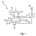
- an internal combustion engine bears the reference number 10 as a whole. It is typically operated on the four-stroke principle, that is to say that one working cycle comprises four cycles. Used is such an internal combustion engine, for example in motor vehicles. It comprises a combustion chamber 12, to which air is supplied via an intake pipe 14. Fuel is injected into the combustion chamber 12 through a high pressure injector 16. This is fed from a fuel rail 18, also referred to as a "rail", in which the fuel is supplied under very high pressure. The ignition of the fuel-air mixture formed in the combustion chamber 12 is effected by an ignition device 20, preferably a spark plug. By the expansion of the burning air-fuel mixture a piston 22 is moved. The operating state of the internal combustion engine 10, in particular the position of the piston 22, is detected by a sensor 24. The hot combustion exhaust gases are discharged through an exhaust pipe 26.
- the internal combustion engine 10 comprises a control and regulating device 28, to which the power requirement of a user is communicated by means of an accelerator pedal 30. Furthermore, the control and regulating device 28 still receives signals from the sensor 24. On the output side, it is u.a. connected to the injection valve 16 and the ignition system 20.
- the fuel In order to homogenize, i. To achieve the most uniform possible mixing of the fuel injected from the injection valve 16 into the combustion chamber 12 with the air sucked in through the intake pipe 14, the fuel is generally collected very early, i. already at the beginning of the downward movement of the piston 22 in the intake phase of the internal combustion engine 10, injected.
- the relevant angle of the crankshaft (not shown) of the internal combustion engine 10 is detected by the sensor 24 and forwarded a corresponding signal to the control and regulating device 28.
- the injection valve 16 is controlled by the control and regulating device 28 so that it opens and closes in pulses, wherein the opening time of the injection valve 16 0.5 ms does not exceed.
- the amount of fuel entering the combustion chamber 12 during an injection pulse, that is to say during a coherent opening time of the injection valve 16, should normally not exceed approximately 5 mm 3 . With such a pulse duration and such an amount of fuel injected per pulse, the penetration depth of the fuel in the combustion chamber 12 decreases so that the fuel no longer impacts the wall of the combustion chamber 12 opposite the injection valve 16.
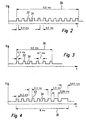
- FIGS. 2 to 7 different embodiments of possible pulse sequences for the fuel injection into the combustion chamber 12 are shown.
- the individual injection pulses carry the reference numeral 32, whereas the pauses between two injection pulses carry the reference numeral 34.
- the entire injection of a duty cycle of the internal combustion engine is indicated at 36.
- the time intervals between two pulses 32 over the duration of an injection are the same length and approximately 0.5 ms.
- the duration of an injection pulse 32 itself is about 0.3 ms.
- the duration of the total injection 36 is approximately 9.5 ms in the exemplary embodiment illustrated in FIG.
- a fuel quantity of a total of 60 mm 3 is injected during the injection 36 shown in FIG. 2.
- the time window available for injection is approximately 11 ms. The amount of fuel to be injected at full load of 60 mm 3 can thus be introduced into the combustion chamber 12 of the internal combustion engine 10 without problems.
- the embodiment shown in Fig. 3 is intended for an operating condition of the internal combustion engine 10, in which this at a speed of 5000 revolutions / min working in the partial load range.
- the time window available for injection 36 is approximately 9 ms long. With the six injection pulses 32 of 0.3 ms duration and pauses 34 of 0.7 ms duration results in a total duration of the injection of 5.5 ms at a partial load corresponding to the injection amount of 30 mm 3 .
- the intervals between the injection pulses can be shortened in an exemplary embodiment which is not illustrated.
- a time window for the injection of approximately 7.5 ms is available.
- twelve injection pulses suffice, each injecting approximately 5 mm 3 of fuel, and each spaced 0.33 ms apart from each other. The resulting total injection duration of 7.3 ms is well within the available time window.
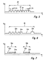
- the duration of the injection pulses 32 increases toward the end of the total injection 36.
- a procedure is indicated, for example, when the injection takes place not only during the intake phase but also during the compression phase of the internal combustion engine 10. Since the pressure in the combustion chamber 12 increases during the compression phase, the penetration depth decreases with a constant injection partial quantity or, with the same penetration depth, a larger injection partial quantity per injection pulse 32 can be selected.
- the duration of the Total Injection 36 is approximately 8 ms, with the duration of an injection pulse 32 increasing from 0.3 ms to 0.5, further to 0.66 and finally to 0.83 ms towards the end of the injection. It is also possible to increase the injection quantity toward the end of an injection 36 in that the duration of the pauses 34 between two injection pulses 32 is reduced. Such an embodiment is shown in FIG.
- FIG. 7 Embodiment in which within a working cycle of the internal combustion engine 10, two injections 36a and 36b are carried out, each of which in turn consists of individual injection pulses 32a and 32b with intervening pauses 34a and 34b.
Description
Die vorliegende Erfindung betrifft ein Verfahren zum Betreiben einer Brennkraftmaschine, insbesondere eines Kraftfahrzeugs, bei dem Benzin mittels eines Einspritzventils mit mindestens einer Einspritzung pro Arbeitszyklus während einer Ansaugphase direkt in einen Brennraum der Brennkraftmaschine eingespritzt wird.The present invention relates to a method for operating an internal combustion engine, in particular a motor vehicle, in which gasoline is injected by means of an injection valve with at least one injection per working cycle during a suction directly into a combustion chamber of the internal combustion engine.
Ein solches Verfahren ist vom Markt her bekannt. Es wird auch als Benzin-Direkteinspritzung (BDE) bezeichnet. Bei diesem Verfahren wird der Kraftstoff mit sehr hohem Druck über direkt am Brennraum angeordnete Einspritzventile in den Brennraum der Brennkraftmaschine eingespritzt. Die Brennkraftmaschine arbeitet dabei zyklisch: Bei einer Viertakt-Brennkraftmaschine umfasst ein Arbeitszyklus beispielsweise vier Arbeitstakte.Such a method is known from the market. It is also known as gasoline direct injection (BDE). In this method, the fuel is injected at very high pressure via directly arranged on the combustion chamber injection valves in the combustion chamber of the internal combustion engine. The internal combustion engine operates cyclically: In a four-stroke internal combustion engine, a duty cycle comprises, for example, four work cycles.
Bei dem bekannten Verfahren wurde jedoch festgestellt, dass der gesamte eingespritzte Kraftstoff nicht immer optimal verbrennt. Dies führt in manchen Betriebszuständen der Brennkraftmaschine zu einem noch nicht optimal ökonomischen Kraftstoffeinsatz. Darüber hinaus führt eine unvollständige Verbrennung des eingespritzten Kraftstoffs zu HC-Emissionen oder Rußemissionen. Es wurde festgestellt, dass dieses Problem verstärkt im kalten Zustand der Brennkraftmaschine auftritt.In the known method, however, it was found that the entire injected fuel does not always burn optimally. This leads in some operating states of the internal combustion engine to a not yet optimally economical fuel use. In addition, incomplete combustion of the injected fuel results in HC emissions or soot emissions. It has been found that this problem occurs more in the cold state of the internal combustion engine.
Aus der US 5,280,773 ist eine Diesel-Brennkraftmaschine bekannt, bei der ein sehr schnell öffnendes und schließendes Einspritzventil eingesetzt wird. Auf diese Weise kann eine Einspritzung mit einer bestimmten Impulsfrequenz realisiert werden.From US 5,280,773 a diesel internal combustion engine is known in which a very fast opening and closing injector is used. In this way, an injection with a certain pulse frequency can be realized.
Die vorliegende Erfindung hat daher die Aufgabe, ein Verfahren der eingangs genannten Art so weiterzubilden, dass der Kraftstoffeinsatz noch weiter optimiert wird und gleichzeitig die Emissionen reduziert werden.The present invention therefore has the task of developing a method of the type mentioned so that the fuel use is further optimized and at the same time the emissions are reduced.
Diese Aufgabe wird bei einem Verfahren der eingangs genannten Art dadurch gelöst, dass eine Kraftstoffeinspritzung während einer Ansaugphase eine Mehrzahl von zeitlich voneinander beabstandeten kurzen Einspritzimpulsen umfasst, wobei mindestens ein Impuls so kurz ist, dass das durch ihn in den Brennraum eingespritzte Benzin nicht auf die dem Einspritzventil gegenüber liegende Wand prallt.This object is achieved in a method of the type mentioned above in that a fuel injection during a suction comprises a plurality of temporally spaced short injection pulses, wherein at least one pulse is so short that the gasoline injected through it into the combustion chamber does not affect the Injector opposite wall bounces.
Dem erfindungsgemäßen Verfahren liegt zunächst folgender Gedanke zugrunde: Um eine Homogenisierung, d.h. möglichst gleichmäßige Vermischung des eingespritzten Kraftstoffs mit der Luft im Brennraum zu erreichen, wird der Kraftstoff sehr früh, u.U. schon zu Beginn der Abwärtsbewegung des Kolbens in der Ansaugphase eingespritzt. In dieser Phase ist der Druck im Brennraum relativ niedrig und beträgt typischerweise weniger als 1 bar. Es wurde nun festgestellt, dass bei längeren Öffnungszeiten des Einspritzventils bei einem solch niedrigen Druck im Brennraum der Kraftstoff vom Einspritzventil auf die dem Einspritzventil gegenüberliegende Wand des Brennraums prallt und an dieser Wand als Auftrag haften bleibt. Ein solcher aus Kraftstoff bestehender Wandauftrag an der Wand des Brennraums ist jedoch nur schwer verdampfbar und führt daher zu einem nicht optimalen Gemisch im Brennraum.The method according to the invention is initially based on the following idea: In order to achieve homogenization, ie mixing of the injected fuel as uniformly as possible with the air in the combustion chamber, the fuel is injected very early, possibly already at the beginning of the downward movement of the piston in the intake phase. In this phase, the pressure in the combustion chamber is relatively low and is typically less as 1 bar. It has now been found that at longer opening times of the injection valve at such a low pressure in the combustion chamber, the fuel from the injection valve to the injection valve opposite wall of the combustion chamber bounces and adhere to this wall as an order. However, such an existing from fuel wall application to the wall of the combustion chamber is difficult to evaporate and therefore leads to a non-optimal mixture in the combustion chamber.
Die Dauer eines einzelnen kurzen Einspritzimpulses der Mehrzahl von Einspritzimpulsen einer einzelnen Kraftstoffeinspritzung ist deutlich kürzer als die Gesamtdauer der einzelnen Kraftstoffeinspritzung. Unter einem kurzen Einspritzimpuls wird erfindungsgemäß also eine Einspritzung verstanden, bei der nur ein kleiner Teil der bei der Einzeleinspritzung in den Brennraum der Brennkraftmaschine einzubringenden Kraftstoffmenge tatsächlich eingespritzt wird. Ein derartiger Einspritzimpuls unterscheidet sich also von den Einzeleinspritzungen heute bekannter Doppel- oder Dreifacheinspritzungen.The duration of a single short injection pulse of the plurality of injection pulses of a single fuel injection is significantly shorter than the total duration of the single fuel injection. Under According to the invention, therefore, a short injection pulse is understood to mean an injection in which only a small part of the fuel quantity to be introduced into the combustion chamber of the internal combustion engine during the individual injection is actually injected. Such an injection pulse thus differs from the individual injections known today double or triple injections.
Hierdurch sinkt die entsprechende Eindringtiefe des Kraftstoffes bei einem solchen Einspritzimpuls. Auf diese Weise wird verhindert, dass der bei einem Einspritzimpuls in den Brennraum eingespritzte Kraftstoff auf die dem Einspritzventil gegenüberliegende Wand prallt und zu dem eingangs genannten Wandauftrag führt. Je kürzer die Dauer eines Einspritzimpulses ist, umso eher ist sichergestellt, dass der solchermaßen eingespritzte Kraftstoff sich mit der im Brennraum befindlichen Luft vermischt und sich nicht an der Brennraumwand niederschlägt. Bei dem erfindungsgemäßen Verfahren findet also keine kontinuierliche Einspritzung statt, sondern eine gepulste Einspritzung, welche auch als "gechopped" bezeichnet wird.As a result, the corresponding penetration depth of the fuel decreases with such an injection pulse. In this way it is prevented that the fuel injected into the combustion chamber during an injection pulse impacts on the wall opposite the injection valve and leads to the wall application mentioned above. The shorter the duration of an injection pulse, the sooner it is ensured that the thus injected fuel mixes with the air in the combustion chamber and does not precipitate on the combustion chamber wall. In the method according to the invention, therefore, there is no continuous injection, but a pulsed injection, which is also referred to as "chopped".
Da bei dem erfindungsgemäßen Verfahren sich der in den Brennraum eingespritzte Kraftstoff im Wesentlichen vollständig mit der im Brennraum befindlichen Luft vermischt, wird der Kraftstoff optimal verbrannt, was den spezifischen Kraftstoffverbrauch senkt und das Emissionsverhalten verbessert. Da der Niederschlag des eingespritzten Kraftstoffes an der Brennraumwand bei kalter Brennraumwand besonders markant ist und dieser Niederschlag bei dem erfindungsgemäßen Verfahren weniger oder überhaupt nicht auftritt, wird das Kaltstartverhalten der Brennkraftmaschine mit dem erfindungsgemäßen Verfahren in besonderer Weise verbessert.Since, in the method according to the invention, the fuel injected into the combustion chamber essentially completely mixes with the air in the combustion chamber, the fuel is optimally burned, which reduces the specific fuel consumption and improves the emission behavior. Since the precipitation of the injected fuel on the combustion chamber wall is particularly pronounced in the case of a cold combustion chamber wall and this precipitation occurs less or not at all in the method according to the invention, the cold start behavior of the internal combustion engine is improved in a particular way with the method according to the invention.
Vorteilhafte Weiterbildungen der Erfindung sind in Unteransprüchen angegeben.Advantageous developments of the invention are specified in subclaims.
In einer ersten Weiterbildung ist angegeben, dass die bei einer Einspritzung in den Brennraum gelangende Kraftstoffmenge wenigstens auch durch die Dauer der einzelnen Einspritzimpulse eingestellt wird. Zur Steuerung der Leistung der Brennkraftmaschine muss die insgesamt pro Arbeitstakt in den Brennraum eingespritzte Kraftstoffmenge eingestellt werden können. Hierfür bietet die Einstellung der Dauer der einzelnen Einspritzimpulse eine einfache Möglichkeit. Dabei muss allerdings darauf geachtet werden, dass die Dauer eines einzelnen Einspritzimpulses niemals jene Dauer erreicht, bei der die kritische Eindringtiefe überschritten wird. Unter der kritischen Eindringtiefe wird jene Eindringtiefe verstanden, bei der der eingespritzte Kraftstoff auf die dem Einspritzventil gegenüberliegende Wand des Brennraums prallt.In a first embodiment, it is stated that the amount of fuel reaching the combustion chamber during an injection is also set at least by the duration of the individual injection pulses. To control the power of the internal combustion engine, the total per fuel stroke injected into the combustion chamber fuel amount must be able to be set. For this purpose, setting the duration of the individual injection pulses offers an easy possibility. However, care must be taken to ensure that the duration of a single injection pulse never reaches the duration at which the critical penetration depth is exceeded. The critical penetration depth is understood to mean that penetration depth at which the injected fuel impinges on the wall of the combustion chamber opposite the injection valve.
Besonders bevorzugt ist die Einstellung der Leistung der Brennkraftmaschine dadurch, dass die bei einer Einspritzung in den Brennraum gelangende Kraftstoffmenge wenigstens auch durch die Anzahl der einzelnen Einspritzimpulse eingestellt wird.The setting of the power of the internal combustion engine is particularly preferably characterized in that the amount of fuel reaching the combustion chamber when injected is at least also set by the number of individual injection pulses.
Am einfachsten ist das erfindungsgemäße Verfahren dadurch zu realisieren, dass die Einspritzimpulse über die Gesamtdauer einer Einspritzung gleichmäßig verteilt sind. Ebenso einfach ist das erfindungsgemäße Verfahren dann, wenn sich die Dauer der Einspritzimpulse über die Gesamtdauer einer Einspritzung nicht verändert. Erfolgt die Einspritzung während der Ansaugphase des Kolbens, trifft jede von einem Einspritzimpuls eingespritzte Teilmenge an Kraftstoff in ein neues angesaugtes Luftvolumen, was zu Vorteilen bei der Verteilung des Kraftstoffs in der Luft im Brennraum führt.The simplest method of the invention is to realize that the injection pulses are evenly distributed over the entire duration of an injection. The method according to the invention is just as simple if the duration of the injection pulses does not change over the entire duration of an injection. When injection occurs during the intake phase of the piston, each subset of fuel injected by an injection pulse encounters a new volume of air drawn in, resulting in benefits in the distribution of the fuel in the air in the combustion chamber.
Möglich ist aber auch, dass der zeitliche Abstand zwischen zwei Einspritzimpulsen über die Dauer einer Einspritzung sich verändert. Hierdurch kann der Tatsache Rechnung getragen werden, dass die Kolbengeschwindigkeit während der Ansaugphase nicht konstant ist und insoweit auch die pro Zeiteinheit angesaugten Luftvolumina nicht die gleiche Größe haben. Dies bedeutet wiederum, dass die Kraftstoffverteilung in der Luft im Brennraum optimiert werden kann.However, it is also possible that the time interval between two injection pulses changes over the duration of an injection. In this way, the fact can be taken into account that the piston speed is not constant during the intake phase and, to that extent, the air volumes sucked in per unit time are not the same size. This in turn means that the fuel distribution in the air in the combustion chamber can be optimized.
Besonders bevorzugt ist es, wenn die Dauer eines Einspritzimpulses über die Gesamtdauer einer Einspritzung sich verändert, vorzugsweise zunimmt. Diese Variante des erfindungsgemäßen Verfahrens ist dann besonders von Vorteil, wenn die Einspritzung nicht nur während der Ansaugphase sondern auch noch während der Verdichtungsphase der Brennkraftmaschine erfolgt. Da bei der Verdichtungsphase der Brennkraftmaschine der Druck im Brennraum ansteigt, kann auch mit der bei einem längeren Einspritzimpuls vorliegenden größeren Einspritzteilmenge eine Wandbenetzung zuverlässig vermieden werden.It is particularly preferred if the duration of an injection pulse changes over the total duration of an injection, preferably increases. This variant of the method according to the invention is particularly advantageous if the injection takes place not only during the intake phase but also during the compression phase of the internal combustion engine. Since the pressure in the combustion chamber rises during the compression phase of the internal combustion engine, wall wetting can be reliably prevented even with the larger injection partial amount present during a longer injection pulse.
Bei einer besonders bevorzugten Weiterbildung des erfindungsgemäßen Verfahrens ist vorgesehen, dass am Ende einer Einspritzung ein einzelner Einspritzimpuls erfolgt, der länger dauert als die vorhergehenden Einspritzimpulse der Einspritzung. Mit einer solchen Einspritzstrategie kann z.B. in ein homogen mageres Gemisch im Brennraum bei weit angestiegenem Kolben (also gegen Ende der Kompressionsphase der Brennkraftmaschine) noch eine Restmenge eingespritzt werden, die zusammen mit der homogen mageren Füllung, welche zuvor durch eine Mehrzahl von kurzen Einspritzimpulsen eingebracht wurde, innerhalb der entstehenden Gemischwolke im Brennraum etwa Stöchiometrie erzeugt (Schichtung aus stöchiometrischer Gemischwolke und homogen magerer Umgebung). Dieses Verfahren hat den Vorteil, dass extrem magere homogene Grundgemische vollständig verbrannt ("durchgebrannt") werden können, da zuvor ein wesentlicher Teil des Brennraumvolumens stöchiometrisch verbrannt wurde und somit die homogen magere Umgebung aufgeheizt und verdichtet wurde.In a particularly preferred development of the method according to the invention, it is provided that at the end of an injection, a single injection pulse takes place, which lasts longer than the preceding injection pulses of the injection. With such an injection strategy, for example, in a homogeneously lean mixture in the combustion chamber at far increased piston (ie towards the end of the compression phase of the internal combustion engine) still a residual amount to be injected, which was previously introduced by a plurality of short injection pulses together with the homogeneous lean filling , Stoichiometry generated within the resulting mixture cloud in the combustion chamber (stratification of stoichiometric mixture cloud and homogeneous lean environment). This procedure has the Advantage that extremely lean homogeneous basic mixtures can be completely burned ("burned"), as previously a substantial part of the combustion chamber volume was stoichiometrically burned and thus the homogeneous lean environment was heated and compressed.
Bei einer anderen Weiterbildung ist angegeben, dass pro Einspritzimpuls in etwa 5 mm3 Kraftstoff eingespritzt werden und/oder ein Einspritzimpuls nicht länger als ungefähr 0,5 ms dauert. Mit diesen Werten kann unter normalen Betriebsbedingungen ein Aufprallen des eingespritzten Kraftstoffes auf die dem Einspritzventil gegenüberliegende Wand des Brennraums zuverlässig vermieden werden.In another embodiment it is stated that approximately 5 mm 3 of fuel are injected per injection pulse and / or an injection pulse does not take longer than approximately 0.5 ms. With these values, under normal operating conditions, impact of the injected fuel on the wall of the combustion chamber opposite the injection valve can be reliably avoided.
Schließlich ist noch angegeben, dass mehrere Kraftstoffeinspritzungen pro Arbeitszyklus erfolgen, von denen mindestens eine wiederum aus mehreren Einspritzimpulsen besteht. So ist es z.B. möglich, eine Einspritzung in der Ansaugphase und eine andere Einspritzung während der Kompressionsphase der Brennkraftmaschine durchzuführen. Eine solche Vorgehensweise hat Vorteile im Hinblick auf die Klopfempfindlichkeit der Brennkraftmaschine.Finally, it is stated that several fuel injections are carried out per working cycle, of which at least one in turn consists of several injection pulses. So it is e.g. possible to perform an injection in the intake phase and another injection during the compression phase of the internal combustion engine. Such an approach has advantages in terms of the knock sensitivity of the internal combustion engine.
Die vorliegende Erfindung betrifft auch ein Computerprogramm, welches zur Durchführung des obigen Verfahrens geeignet ist, wenn es auf einem Computer ausgeführt wird. Dabei ist besonders bevorzugt, wenn das Computerprogramm auf einem Speicher, insbesondere auf einem Flash-Memory, abgespeichert ist.The present invention also relates to a computer program suitable for carrying out the above method when executed on a computer. It is particularly preferred if the computer program is stored on a memory, in particular on a flash memory.
Weiterhin betrifft die vorliegende Erfindung ein Steuer- und/oder Regelgerät zum Betreiben einer Brennkraftmaschine, insbesondere eines Kraftfahrzeugs, bei der der Kraftstoff direkt in einen Brennraum der Brennkraftmaschine eingespritzt wird. Um den Betrieb der Brennkraftmaschine im Hinblick auf den Kraftstoffverbrauch und das Emissionsverhalten zu optimieren, wird erfindungsgemäß vorgeschlagen, dass das Steuer- und/oder Regelgerät zur Steuerung und/oder Regelung des obigen Verfahrens geeignet ist.Furthermore, the present invention relates to a control and / or regulating device for operating an internal combustion engine, in particular a motor vehicle, in which the fuel directly into a combustion chamber of the internal combustion engine is injected. In order to optimize the operation of the internal combustion engine in terms of fuel consumption and emission behavior, the invention proposes that the control and / or regulating device is suitable for controlling and / or regulating the above method.
Dabei ist besonders bevorzugt, wenn das Steuer- und/oder Regelgerät mit einem Computerprogramm der oben genannten Art versehen ist.It is particularly preferred if the control and / or regulating device is provided with a computer program of the type mentioned above.
Die vorliegende Erfindung betrifft ferner noch eine Brennkraftmaschine mit mindestens einem Brennraum und einer Einrichtung, welche den Kraftstoff direkt in den Brennraum einspritzt. Um das Betriebsverhalten dieser Brennkraftmaschine zu verbessern, insbesondere den Kraftstoffverbrauch, das Emissionsverhalten sowie das Kaltstartverhalten, wird erfindungsgemäß vorgeschlagen, dass sie mit einem Steuer- und/oder Regelgerät der oben genannten Art versehen ist.The present invention further relates to an internal combustion engine with at least one combustion chamber and a device which injects the fuel directly into the combustion chamber. In order to improve the operating behavior of this internal combustion engine, in particular the fuel consumption, the emission behavior and the cold start behavior, the invention proposes that it is provided with a control and / or regulating device of the type mentioned above.
Nachfolgend werden Ausführungsbeispiele der Erfindung unter Bezugnahme auf die beiliegende Zeichnung im Detail erläutert. In der Zeichnung zeigen:
- Fig. 1:
- eine Prinzipdarstellung einer Brennkraftmaschine mit Benzin-Direkteinspritzung;
- Fig. 2:
- ein Diagramm eines ersten Ausführungsbeispiels eines Verfahrens zum.Betreiben der Brennkraftmaschine von Fig. 1, in dem die eingespritzte Kraftstoffmenge über der Zeit dargestellt ist;
- Fig. 3:
- ein Diagramm ähnlich Fig. 2 eines zweiten Ausführungsbeispiels eines Verfahrens zum Betreiben der Brennkraftmaschine von Fig. 1;
- Fig. 4:
- ein Diagramm ähnlich Fig. 2 eines dritten Ausführungsbeispiels eines Verfahrens zum Betreiben der Brennkraftmaschine von Fig. 1;
- Fig. 5:
- ein Diagramm ähnlich Fig. 2 eines vierten Ausführungsbeispiels eines Verfahrens zum Betreiben der Brennkraftmaschine von Fig. 1;
- Fig. 6:
- ein Diagramm ähnlich Fig. 2 eines fünften Ausführungsbeispiels eines Verfahrens zum Betreiben der Brennkraftmaschine von Fig. 1; und
- Fig. 7:
- ein Diagramm ähnlich Fig. 2 eines sechsten Ausführungsbeispiels eines Verfahrens zum Betreiben der Brennkraftmaschine von Fig. 1.
- Fig. 1:
- a schematic diagram of an internal combustion engine with gasoline direct injection;
- Fig. 2:
- a diagram of a first embodiment of a method for operating the internal combustion engine of Figure 1, in which the injected amount of fuel over time is shown.
- 3:
- a diagram similar to Figure 2 of a second embodiment of a method for operating the internal combustion engine of Fig. 1.
- 4:
- a diagram similar to Figure 2 of a third embodiment of a method for operating the internal combustion engine of Fig. 1.
- Fig. 5:
- a diagram similar to Figure 2 of a fourth embodiment of a method for operating the internal combustion engine of Fig. 1.
- Fig. 6:
- a diagram similar to Figure 2 of a fifth embodiment of a method for operating the internal combustion engine of Fig. 1. and
- Fig. 7:
- 2 is a diagram similar to FIG. 2 of a sixth exemplary embodiment of a method for operating the internal combustion engine of FIG. 1.
Eine Brennkraftmaschine trägt in Fig. 1 insgesamt das Bezugszeichen 10. Typischerweise wird sie nach dem Viertaktprinzip betrieben, ein Arbeitszyklus umfasst also vier Takte. Eingesetzt wird eine solche Brennkraftmaschine z.B. in Kraftfahrzeugen. Sie umfasst einen Brennraum 12, dem Luft über ein Ansaugrohr 14 zugeführt wird. Kraftstoff wird in den Brennraum 12 durch ein Hochdruck-Einspritzventil 16 eingespritzt. Dieses wird aus einer Kraftstoff-Sammelleitung 18 gespeist, welche auch als "Rail" bezeichnet wird und in der der Kraftstoff unter sehr hohem Druck bereitgestellt wird. Die Zündung des im Brennraum 12 gebildeten Kraftstoff-Luftgemisches erfolgt durch eine Zündeinrichtung 20, vorzugsweise eine Zündkerze. Durch die Expansion des verbrennenden Luft-Kraftstöffgemisches wird ein Kolben 22 bewegt. Der Betriebszustand der Brennkraftmaschine 10, insbesondere die Position des Kolbens 22, wird durch einen Sensor 24 erfasst. Die heißen Verbrennungsabgase werden durch ein Abgasrohr 26 abgeleitet.In FIG. 1, an internal combustion engine bears the
Die Brennkraftmaschine 10 umfasst ein Steuer- und Regelgerät 28, dem die Leistungsanforderung eines Benutzers durch ein Gaspedal 30 mitgeteilt wird. Ferner erhält das Steuer- und Regelgerät 28 noch Signale vom Sensor 24. Ausgangsseitig ist es u.a. mit dem Einspritzventil 16 und der Zündanlage 20 verbunden.The
Um eine Homogenisierung, d.h. eine möglichst gleichmäßige Vermischung des vom Einspritzventil 16 in den Brennraum 12 eingespritzten Kraftstoffes mit der durch das Ansaugrohr 14 angesaugten Luft zu erreichen, wird der Kraftstoff im Allgemeinen sehr früh, d.h. schon zu Anfang der Abwärtsbewegung des Kolbens 22 in der Ansaugphase der Brennkraftmaschine 10, eingespritzt. Der relevante Winkel der Kurbelwelle (nicht dargestellt) der Brennkraftmaschine 10 wird dabei vom Sensor 24 erfasst und ein entsprechendes Signal an das Steuer- und Regelgerät 28 weitergeleitet.In order to homogenize, i. To achieve the most uniform possible mixing of the fuel injected from the
Da während dieser Phase im Brennraum 12 ein relativ geringer Druck herrscht (im Allgemeinen höchstens ungefähr 1 bar), besteht die Gefahr, dass der vom Einspritzventil 16 unter hohem Druck in den Brennraum 12 eingespritzte Kraftstoff auf die dem Einspritzventil 16 gegenüberliegende Wand (nicht dargestellt) des Brennraums 12 oder die Oberseite des Kolbens 22 prallt und dort anhaftet. Ein solcher Kraftstoffauftrag auf die Wand oder den Kolben 22 ist schwer verdampfbar und nimmt nicht oder zumindest nicht in der gewünschten Weise an der Verbrennung im Brennraum 12 teil, was den Kraftstoffverbrauch erhöht und das Emissionsverhalten verschlechtert. Das Problem des Niederschlags des Kraftstoffs an einer Wand des Brennraums 12 ist dann besonders markant, wenn die Wand des Brennraums 12 kalt ist. In diesem Fall wäre also das Kaltstartverhalten der Brennkraftmaschine 10 beeinträchtigt.Since during this phase in the
Um zu vermeiden, dass es zu einem solchen Niederschlag des Kraftstoffes an einer Wand des Brennraums 12 kommt, wird das Einspritzventil 16 von dem Steuer- und Regelgerät 28 so angesteuert, dass es impulsartig öffnet und schließt, wobei die Öffnungszeit des Einspritzventils 16 0,5 ms nicht überschreitet. Die während eines Einspritzimpulses, also während einer zusammenhängenden Öffnungszeit des Einspritzventils 16, in den Brennraum 12 gelangende Kraftstoffmenge sollte dabei im Normalfall ungefähr 5 mm3 nicht übersteigen. Bei einer derartigen Impulsdauer und einer derartigen pro Impuls eingespritzten Kraftstoffmenge sinkt die Eindringtiefe des Kraftstoffes im Brennraum 12, so dass der Kraftstoff nicht mehr auf die dem Einspritzventil 16 gegenüberliegende Wand des Brennraums 12 prallt .In order to avoid that such a precipitation of the fuel on a wall of the
Durch die diskontinuierliche, also aus einer Folge einzelner Einspritzimpulse bestehende Einspritzung des Kraftstoffes in den Brennraum 12 wird die Eindringtiefe des Kraftstoffes in den Brennraum 12 reduziert. Die Gefahr, dass der Kraftstoff sich an der dem Einspritzventil 16 gegenüberliegenden Wand des Brennraums niederschlägt, wird wirkungsvoll verringert.Due to the discontinuous, ie from a sequence of individual injection pulses existing injection of the fuel into the
Hierdurch wird sichergestellt, dass der in den Brennraum 12 eingespritzte Kraftstoff möglichst vollständig als Luft-Kraftstoffgemisch im Brennraum 12 vorliegt und somit eine optimale Verbrennung des eingespritzten Kraftstoffes erfolgt. Dies senkt den Kraftstoffverbrauch und verbessert das Emissionsverhalten, insbesondere die HC- oder Rußemissionen. Besonders günstig wirkt sich die verringerte Eindringtiefe des Kraftstoffes in den Brennraum 12 dann aus, wenn die Wand des Brennraums 12 kalt ist, also beim Kaltstart der Brennkraftmaschine 10. Auch in solchen Fällen kann durch das erfindungsgemäße Verfahren sichergestellt werden, dass ein zündfähiges Luft-Kraftstoffgemisch im Brennraum 12 der Brennkraftmaschine 10 vorliegt.This ensures that the fuel injected into the
In den in den Fig. 2 bis 7 dargestellten Diagrammen sind verschiedene Ausführungsbeispiele möglicher Impulsfolgen für die Kraftstoffeinspritzung in den Brennraum 12 dargestellt. Die einzelnen Einspritzimpulse tragen das Bezugszeichen 32, wohingegen die Pausen zwischen zwei Einspritzimpulsen das Bezugszeichen 34 tragen. Die gesamte Einspritzung eines Arbeitszyklus der Brennkraftmaschine ist mit 36 gekennzeichnet.In the diagrams shown in FIGS. 2 to 7 different embodiments of possible pulse sequences for the fuel injection into the
Bei dem in Fig. 2 dargestellten Ausführungsbeispiel einer Impulsfolge sind die zeitlichen Abstände 34 zwischen zwei Impulsen 32 über die Dauer einer Einspritzung gleich lang und betragen ungefähr 0,5 ms. Die Dauer eines Einspritzimpulses 32 selbst beträgt ungefähr 0,3 ms. Die Dauer der gesamten Einspritzung 36 beträgt bei dem in Fig. 2 dargestellten Ausführungsbeispiel ungefähr 9,5 ms. Bei einer Einspritzmenge von 5 mm3 pro Einspritzimpuls 32 wird während der in Fig. 2 dargestellten Einspritzung 36 eine Kraftstoffmenge von insgesamt 60 mm3 eingespritzt. Bei einer Drehzahl von 4000 Umdrehungen/min ist das für die Einspritzung zur Verfügung stehende Zeitfenster ungefähr 11 ms lang. Die bei Volllast einzuspritzende Kraftstoffmenge von 60 mm3 kann also problemlos in den Brennraum 12 der Brennkraftmaschine 10 eingbracht werden.In the embodiment of a pulse train illustrated in FIG. 2, the time intervals between two
Das in Fig. 3 dargestellte Ausführungsbeispiel ist für einen Betriebszustand der Brennkraftmaschine 10 gedacht, bei dem diese mit einer Drehzahl von 5000 Umdrehungen/min im Teillastbereich arbeitet. Dies bedeutet, dass bei einer Einspritzung 36 eine Einspritzmenge von ungefähr 30 mm3 eingespritzt werden soll. Das für eine Einspritzung 36 zur Verfügung stehende Zeitfenster ist ungefähr 9 ms lang. Mit den sechs Einspritzimpulsen 32 von 0,3 ms Dauer und Pausen 34 von 0,7 ms Dauer ergibt sich eine Gesamtdauer der Einspritzung von 5,5 ms bei einer der Teillast entsprechenden Einspritzmenge von 30 mm3.The embodiment shown in Fig. 3 is intended for an operating condition of the
Soll z.B. bei einer höheren Drehzahl und Volllast eine größere Kraftstoffmenge in den Brennraum 12 der Brennkraftmaschine 10 eingespritzt werden, können in einem nicht dargestellten Ausführungsbeispiel die Pausen zwischen den Einspritzimpulsen verkürzt werden. Bei einer Drehzahl der Brennkraftmaschine 10 von beispielsweise 6000 Umdrehungen/min steht ein Zeitfenster für die Einspritzung von ungefähr 7,5 ms zur Verfügung. Um eine Einspritzmenge von 60 mm3 einzuspritzen, genügen zwölf Einspritzimpulse, welche jeweils ungefähr 5 mm3 Kraftstoff einspritzen, und welche jeweils 0,33 ms zeitlich voneinander beabstandet sind. Die sich hieraus ergebende Gesamtdauer der Einspritzung von 7,3 ms liegt deutlich innerhalb des zur Verfügung stehenden Zeitfensters.If, for example, a larger quantity of fuel is to be injected into the
Bei dem in Fig. 4 dargestellten Ausführungsbeispiel einer Inmpulsfolge verlängert sich die Dauer der Einspritzimpulse 32 gegen Ende der Gesamteinspritzung 36. Eine solche Vorgehensweise ist z.B. dann angezeigt, wenn die Einspritzung nicht nur während der Ansaugphase, sondern auch während der Kompressionsphase der Brennkraftmaschine 10 erfolgt. Da während der Kompressionsphase der Druck im Brennraum 12 ansteigt, sinkt bei konstanter Einspritzteilmenge die Eindringtiefe bzw. kann bei gleicher Eindringtiefe eine größere Einspritzteilmenge pro Einspritzimpuls 32 gewählt werden. Bei dem dargestellten Ausführungsbeispiel beträgt die Dauer der Gesamteinspritzung 36 ungefähr 8 ms, wobei die Dauer eines Einspritzimpulses 32 gegen Ende der Einspritzung von 0,3 ms auf 0,5, weiter auf 0,66 und schließlich auf 0,83 ms ansteigt. Möglich ist auch, die Einspritzmenge gegen Ende einer Einspritzung 36 dadurch zu erhöhen, dass die Dauer der Pausen 34 zwischen zwei Einspritzimpulsen 32 verringert wird. Ein solches Ausführungsbeispiel ist in Fig. 5 dargestellt.4, the duration of the
Soll eine Schichtung aus einer stöchiometrischen Gemischwolke und einem homogen mageren Gemisch im Brennraum 12 der Brennkraftmaschine 10 erzeugt werden, bietet sich die in Fig. 6 dargestellte Einspritzstrategie an:If a stratification of a stoichiometric mixture cloud and a homogeneous lean mixture in the
Dabei erfolgt nach einer in Serie von Impulsen 32a mit gleichmäßigen Abständen 34a ein einzelner längerer Einspritzimpuls 32b nach einer längeren Pause 34b. Mit der anfänglichen Impulsserie 32a wird im Brennraum 12 ein homogen mageres Gemisch erzeugt. In dieses Gemisch hinein wird, bei weit angestiegenem Kolben 22 während der Kompressionsphase der Brennkraftmaschine 10, über den Einspritzimpuls 32b so viel Kraftstoff eingespritzt, dass eine stöchiometrische Gemischwolke innerhalb des mageren Gemischs entsteht. Diese Betriebsweise hat den Vorteil, dass auch extrem magere homogene Grundgemische vollständig verbrannt werden können, da zuvor ein wesentlicher Teil des Volumens innerhalb des Brennraums 12 stöchiometrisch verbrannt wurde und somit die homogen magere Umgebung aufgeheizt und verdichtet wurde. Der Vorteil der in Fig. 6 dargestellten Einspritzstrategie liegt in dem nochmals verringerten Kraftstoffverbrauch. Eine Einspritzung während der Kompressionsphase der Brennkraftmaschine 10 hat darüber hinaus den Vorteil, dass die Klopfwahrscheinlichkeit der Brennkraftmaschine 10 verringert wird.In this case, after a series of
In die gleiche Richtung geht das in Fig. 7 dargestellte Ausführungsbeispiel, bei dem innerhalb eines Arbeitszyklus der Brennkraftmaschine 10 zwei Einspritzungen 36a und 36b erfolgen, welche jeweils wiederum aus einzelnen Einspritzimpulsen 32a und 32b mit dazwischen liegenden Pausen 34a und 34b bestehen.The same is shown in FIG. 7 Embodiment in which within a working cycle of the
Claims (14)
- Method for operating an internal combustion engine (10), in particular of a motor vehicle, in which petrol is injected directly into a combustion chamber (12) of the internal combustion engine (10) by means of an injection valve (16) with at least one injection (36) per working cycle during an intake phase, characterized in that a fuel injection (36) during an intake phase comprises a plurality of short injection pulses (32) which are at time intervals from one another, at least one pulse being so short that the petrol which is injected into the combustion chamber (12) during the intake phase does not strike against the wall lying opposite the injection valve (16).
- Method according to Claim 1, characterized in that the quantity of fuel which passes into the combustion chamber (12) during an injection process (36) is also set at least by means of the duration of the individual injection pulses (32).
- Method according to one of the preceding claims, characterized in that the quantity of fuel which passes into the combustion chamber (12) during an injection process (36) is also set at least by means of the number of individual injection pulses (32).
- Method according to one of the preceding claims, characterized in that the injection pulses (32) are distributed uniformly over the entire duration of an injection process (36).
- Method according to one of the preceding claims, characterized in that the duration of the injection pulses (32) does not change over the entire duration of an injection process (36).
- Method according to one of the preceding claims, characterized in that the time interval (34) between two injection pulses (32) changes over the duration of an injection process (36).
- Method according to one of the preceding claims, characterized in that the duration of an injection pulse (32) changes, preferably increases, over the entire duration of an injection process (36).
- Method according to one of the preceding claims, characterized in that an individual injection pulse (32b) which lasts longer than the preceding injection pulses (32a) of the injection process (36) takes place at the end of an injection process (36).
- Method according to one of the preceding claims, characterized in that approximately 5 mm3 fuel is injected per injection pulse (32) and/or an injection pulse (32) does not last for longer than approximately 0.5 ms.
- Method according to one of the preceding claims, characterized in that a plurality of fuel injection processes (36a, 36b) take place per working cycle, at least one injection process (36a, 36b) of which is in turn composed of a plurality of injection pulses (32a, 36b).
- Computer program, characterized in that it is programmed for application in a method according to one of the preceding claims.
- Electrical storage medium for an open-loop and/or closed-loop control device (28) of an internal combustion engine (10), characterized in that a computer program for application in a method of Claims 1 to 10 is stored in said storage medium.
- Open-loop and/or closed-loop control device (28) for an internal combustion engine (10), characterized in that it is programmed for application in a method according to one of Claims 1 to 10.
- Internal combustion engine (10), in particular for a motor vehicle, having an open-loop and/or closed-loop control device (28), characterized in that the open-loop and/or closed-loop control device is programmed for application in a method according to one of Claims 1 to 10.
Applications Claiming Priority (3)
| Application Number | Priority Date | Filing Date | Title |
|---|---|---|---|
| DE10105755A DE10105755A1 (en) | 2001-02-08 | 2001-02-08 | Method, computer program and control and / or regulating device for operating an internal combustion engine and internal combustion engine |
| DE10105755 | 2001-02-08 | ||
| PCT/DE2002/000394 WO2002063155A1 (en) | 2001-02-08 | 2002-02-04 | Method, computer program and control and/or regulating appliance for operating an internal combustion engine, and corresponding internal combustion engine |
Publications (2)
| Publication Number | Publication Date |
|---|---|
| EP1364112A1 EP1364112A1 (en) | 2003-11-26 |
| EP1364112B1 true EP1364112B1 (en) | 2006-05-03 |
Family
ID=7673305
Family Applications (1)
| Application Number | Title | Priority Date | Filing Date |
|---|---|---|---|
| EP02706664A Expired - Lifetime EP1364112B1 (en) | 2001-02-08 | 2002-02-04 | Method, computer program and control and/or regulating appliance for operating an internal combustion engine, and corresponding internal combustion engine |
Country Status (5)
| Country | Link |
|---|---|
| US (1) | US6912991B2 (en) |
| EP (1) | EP1364112B1 (en) |
| JP (1) | JP2004518070A (en) |
| DE (3) | DE10105755A1 (en) |
| WO (1) | WO2002063155A1 (en) |
Cited By (1)
| Publication number | Priority date | Publication date | Assignee | Title |
|---|---|---|---|---|
| DE102006030213A1 (en) * | 2006-06-30 | 2008-01-03 | Fev Motorentechnik Gmbh | Homogenized injection process |
Families Citing this family (23)
| Publication number | Priority date | Publication date | Assignee | Title |
|---|---|---|---|---|
| JP2002206446A (en) * | 2001-01-10 | 2002-07-26 | Hitachi Ltd | Internal combustion engine and fuel injection control device for the internal combustion engine |
| DE10320848B4 (en) | 2003-05-09 | 2016-05-04 | Daimler Ag | Method for operating a spark-ignited internal combustion engine |
| DE102004017989B4 (en) * | 2004-04-14 | 2019-03-28 | Daimler Ag | Method for operating an internal combustion engine with direct fuel injection |
| US7458364B2 (en) | 2005-08-05 | 2008-12-02 | Scion-Sprays Limited | Internal combustion engine having a fuel injection system |
| GB2436593B (en) * | 2006-03-28 | 2008-02-20 | Scion Sprays Ltd | An internal combustion engine having a fuel injection system |
| US20070028899A1 (en) * | 2005-08-05 | 2007-02-08 | Jeffrey Allen | Fuel injection unit |
| EP1910659B1 (en) * | 2005-08-05 | 2012-02-01 | Scion-Sprays Limited | A fuel injection system for an internal combustion engine |
| JP2007100623A (en) * | 2005-10-06 | 2007-04-19 | Denso Corp | Fuel injection control device for diesel engine |
| US7360522B2 (en) | 2006-07-25 | 2008-04-22 | General Electric Company | System and method for operating a turbo-charged engine |
| US7770813B2 (en) | 2006-10-11 | 2010-08-10 | Gm Global Technology Operations, Inc. | Spray penetration control method |
| AT502972B1 (en) * | 2006-12-07 | 2008-06-15 | Avl List Gmbh | METHOD FOR OPERATING AN INTERNAL COMBUSTION ENGINE |
| DE102010011105A1 (en) * | 2010-03-11 | 2011-09-15 | Daimler Ag | Method for operating a spark-ignited internal combustion engine |
| JP5011413B2 (en) * | 2010-03-17 | 2012-08-29 | 日立オートモティブシステムズ株式会社 | In-cylinder direct fuel injection internal combustion engine control device |
| DE102010014824B4 (en) * | 2010-04-13 | 2013-09-26 | Continental Automotive Gmbh | Method for operating an internal combustion engine and internal combustion engine |
| JP5809796B2 (en) * | 2010-11-30 | 2015-11-11 | 日立オートモティブシステムズ株式会社 | Fuel injection control device for internal combustion engine |
| CN105452634B (en) * | 2013-08-19 | 2018-12-21 | 罗伯特·博世有限公司 | A kind of method and device thereof controlling fuel injection system |
| WO2015028251A1 (en) * | 2013-08-26 | 2015-03-05 | Robert Bosch Gmbh | A method of controlling a fuel injection system of an internal combustion engine whose fuel injector is fed by gravity |
| WO2015028252A1 (en) * | 2013-08-29 | 2015-03-05 | Robert Bosch Gmbh | A method of controlling a fuel injection system of an internal combustion engine whose fuel injector is fed by gravity |
| JP2018193915A (en) * | 2017-05-17 | 2018-12-06 | マツダ株式会社 | Fuel injection control method and fuel injection control device for diesel engine |
| DE102019214230B4 (en) * | 2019-09-18 | 2022-02-10 | Vitesco Technologies GmbH | Procedure for controlling the total injection mass in multiple injection |
| DE102019219541B4 (en) * | 2019-12-13 | 2021-08-05 | Vitesco Technologies GmbH | Method and engine control for multiple injection with quantity correction for an internal combustion engine |
| DE102021211658A1 (en) | 2021-10-15 | 2023-04-20 | Hitachi Astemo, Ltd. | METHOD AND DEVICE FOR CONTROLLING THE FUEL INJECTION OF AN INTERNAL ENGINE |
| DE102022106869A1 (en) | 2022-03-23 | 2023-09-28 | Volkswagen Aktiengesellschaft | Method for operating a multiple direct injection internal combustion engine and mass-based switching of the number of injections |
Family Cites Families (9)
| Publication number | Priority date | Publication date | Assignee | Title |
|---|---|---|---|---|
| US4579096A (en) * | 1983-12-08 | 1986-04-01 | Toyota Jidosha Kabushiki Kaisha | Diesel fuel injection pump with electromagnetic fuel spilling valve having pilot valve providing high responsiveness |
| DE3936619A1 (en) * | 1989-11-03 | 1991-05-08 | Man Nutzfahrzeuge Ag | METHOD FOR INJECTING A FUEL INTO THE COMBUSTION CHAMBER OF AN AIR COMPRESSING, SELF-IGNITION ENGINE, AND APPARATUS FOR CARRYING OUT THIS METHOD |
| US5168846A (en) * | 1991-06-14 | 1992-12-08 | Paul Marius A | Rotary engine with variable displacement |
| EP0786592B1 (en) | 1996-01-29 | 2002-05-02 | Wärtsilä Schweiz AG | Method and apparatus for injecting fuel in an internal combustion piston engine |
| JP3476202B2 (en) * | 1996-08-29 | 2003-12-10 | 三菱ふそうトラックバス株式会社 | Fuel injection device |
| DE19639172C2 (en) * | 1996-09-24 | 2001-11-08 | Siemens Ag | Direct fuel injection method for a diesel internal combustion engine |
| JP3189734B2 (en) | 1996-12-19 | 2001-07-16 | 三菱自動車工業株式会社 | Spark ignition direct injection internal combustion engine |
| IT1308412B1 (en) * | 1999-03-05 | 2001-12-17 | Fiat Ricerche | METHOD OF COMBUSTION CONTROL OF A DIRECT INJECTION DIESEL ENGINE THROUGH THE IMPLEMENTATION OF MULTIPLE INJECTIONS USING A SYSTEM |
| US6705277B1 (en) * | 2000-07-13 | 2004-03-16 | Caterpillar Inc | Method and apparatus for delivering multiple fuel injections to the cylinder of an engine wherein the pilot fuel injection occurs during the intake stroke |
-
2001
- 2001-02-08 DE DE10105755A patent/DE10105755A1/en not_active Ceased
-
2002
- 2002-02-04 US US10/467,527 patent/US6912991B2/en not_active Expired - Fee Related
- 2002-02-04 JP JP2002562873A patent/JP2004518070A/en active Pending
- 2002-02-04 WO PCT/DE2002/000394 patent/WO2002063155A1/en active IP Right Grant
- 2002-02-04 DE DE50206659T patent/DE50206659D1/en not_active Expired - Lifetime
- 2002-02-04 EP EP02706664A patent/EP1364112B1/en not_active Expired - Lifetime
- 2002-02-04 DE DE10290397T patent/DE10290397D2/en not_active Expired - Lifetime
Cited By (1)
| Publication number | Priority date | Publication date | Assignee | Title |
|---|---|---|---|---|
| DE102006030213A1 (en) * | 2006-06-30 | 2008-01-03 | Fev Motorentechnik Gmbh | Homogenized injection process |
Also Published As
| Publication number | Publication date |
|---|---|
| DE10290397D2 (en) | 2004-01-08 |
| DE10105755A1 (en) | 2002-08-29 |
| EP1364112A1 (en) | 2003-11-26 |
| WO2002063155A1 (en) | 2002-08-15 |
| US20040040534A1 (en) | 2004-03-04 |
| DE50206659D1 (en) | 2006-06-08 |
| JP2004518070A (en) | 2004-06-17 |
| US6912991B2 (en) | 2005-07-05 |
Similar Documents
| Publication | Publication Date | Title |
|---|---|---|
| EP1364112B1 (en) | Method, computer program and control and/or regulating appliance for operating an internal combustion engine, and corresponding internal combustion engine | |
| DE102004053123B4 (en) | Compression ignition internal combustion engine | |
| DE602004012478T2 (en) | Apparatus and method for controlling multiple injection and variable valve timing in a direct injection internal combustion engine | |
| DE112006002990T5 (en) | Method and device for operating a spark-ignited internal combustion engine with direct injection | |
| EP1203145B1 (en) | Method for the operation of a combustion engine | |
| DE112015002732B4 (en) | Control device for internal combustion engine | |
| DE102006035466B4 (en) | Autoignition engine controller that ensures a desired output torque | |
| WO2005103468A1 (en) | Method for operating an internal combustion engine in the after-start phase at low temperatures | |
| DE112009000256T5 (en) | Method and apparatus for controlling a mode change in a spark ignition direct injection engine | |
| DE10111928B4 (en) | Method for starter-free starting a multi-cylinder internal combustion engine | |
| DE102007013119A1 (en) | Injection method and associated internal combustion engine | |
| DE10242227A1 (en) | Operating direct fuel injection combustion engine involves selecting high or low pressure starting using minimum fuel pressure and number of cycles dependent on combustion chamber temperature | |
| DE19815266B4 (en) | Method for injecting fuel into an internal combustion engine | |
| DE102012107714A1 (en) | Control system for a combustion system | |
| EP1703112A1 (en) | Method for heating a catalyst of an internal combustion engine | |
| DE102010029935B4 (en) | Method and device for supplying fuel in an internal combustion engine | |
| DE102010038779A1 (en) | Method for operating an internal combustion engine having a plurality of combustion chambers and internal combustion engine having a plurality of combustion chambers | |
| DE102012212924A1 (en) | Fuel injection control system for internal combustion engine e.g. diesel engine of motor vehicle, has fuel pressure regulating device that is provided to control pressure of fuel passing into fuel injector | |
| WO1999020882A1 (en) | Method for starting an internal combustion engine | |
| DE60133064T2 (en) | Internal combustion engine with external support for stable auto-ignition | |
| WO2003027473A1 (en) | Method for avoiding an internal coking of an injection hole for injection holes in a multi-hole injection valve | |
| DE19913407A1 (en) | Method for operating an internal combustion engine | |
| DE10148651C1 (en) | Automobile internal combustion engine operating method with switching between two operating modes for fuel injection during compression phase or suction phase | |
| WO2017093061A1 (en) | Method and device for operating an internal combustion engine, in particular of a motor vehicle with dual fuel injection | |
| DE10333261B4 (en) | Method for operating a direct injection gasoline engine and directly injecting gasoline engine |
Legal Events
| Date | Code | Title | Description |
|---|---|---|---|
| PUAI | Public reference made under article 153(3) epc to a published international application that has entered the european phase |
Free format text: ORIGINAL CODE: 0009012 |
|
| 17P | Request for examination filed |
Effective date: 20030908 |
|
| AK | Designated contracting states |
Kind code of ref document: A1 Designated state(s): AT BE CH CY DE DK ES FI FR GB GR IE IT LI LU MC NL PT SE TR |
|
| AX | Request for extension of the european patent |
Extension state: AL LT LV MK RO SI |
|
| 17Q | First examination report despatched |
Effective date: 20050209 |
|
| GRAP | Despatch of communication of intention to grant a patent |
Free format text: ORIGINAL CODE: EPIDOSNIGR1 |
|
| GRAS | Grant fee paid |
Free format text: ORIGINAL CODE: EPIDOSNIGR3 |
|
| GRAA | (expected) grant |
Free format text: ORIGINAL CODE: 0009210 |
|
| AK | Designated contracting states |
Kind code of ref document: B1 Designated state(s): DE FR IT |
|
| PG25 | Lapsed in a contracting state [announced via postgrant information from national office to epo] |
Ref country code: IT Free format text: LAPSE BECAUSE OF FAILURE TO SUBMIT A TRANSLATION OF THE DESCRIPTION OR TO PAY THE FEE WITHIN THE PRESCRIBED TIME-LIMIT;WARNING: LAPSES OF ITALIAN PATENTS WITH EFFECTIVE DATE BEFORE 2007 MAY HAVE OCCURRED AT ANY TIME BEFORE 2007. THE CORRECT EFFECTIVE DATE MAY BE DIFFERENT FROM THE ONE RECORDED. Effective date: 20060503 |
|
| REF | Corresponds to: |
Ref document number: 50206659 Country of ref document: DE Date of ref document: 20060608 Kind code of ref document: P |
|
| ET | Fr: translation filed | ||
| PLBE | No opposition filed within time limit |
Free format text: ORIGINAL CODE: 0009261 |
|
| STAA | Information on the status of an ep patent application or granted ep patent |
Free format text: STATUS: NO OPPOSITION FILED WITHIN TIME LIMIT |
|
| 26N | No opposition filed |
Effective date: 20070206 |
|
| PGFP | Annual fee paid to national office [announced via postgrant information from national office to epo] |
Ref country code: IT Payment date: 20140224 Year of fee payment: 13 Ref country code: FR Payment date: 20140218 Year of fee payment: 13 |
|
| PGFP | Annual fee paid to national office [announced via postgrant information from national office to epo] |
Ref country code: DE Payment date: 20150424 Year of fee payment: 14 |
|
| REG | Reference to a national code |
Ref country code: FR Ref legal event code: ST Effective date: 20151030 |
|
| PG25 | Lapsed in a contracting state [announced via postgrant information from national office to epo] |
Ref country code: IT Free format text: LAPSE BECAUSE OF NON-PAYMENT OF DUE FEES Effective date: 20150204 |
|
| PG25 | Lapsed in a contracting state [announced via postgrant information from national office to epo] |
Ref country code: FR Free format text: LAPSE BECAUSE OF NON-PAYMENT OF DUE FEES Effective date: 20150302 |
|
| REG | Reference to a national code |
Ref country code: DE Ref legal event code: R119 Ref document number: 50206659 Country of ref document: DE |
|
| PG25 | Lapsed in a contracting state [announced via postgrant information from national office to epo] |
Ref country code: DE Free format text: LAPSE BECAUSE OF NON-PAYMENT OF DUE FEES Effective date: 20160901 |