EP1363537B1 - Lanzette mit rückzuganordnung für scharfe gegenstände - Google Patents
Lanzette mit rückzuganordnung für scharfe gegenstände Download PDFInfo
- Publication number
- EP1363537B1 EP1363537B1 EP02712595A EP02712595A EP1363537B1 EP 1363537 B1 EP1363537 B1 EP 1363537B1 EP 02712595 A EP02712595 A EP 02712595A EP 02712595 A EP02712595 A EP 02712595A EP 1363537 B1 EP1363537 B1 EP 1363537B1
- Authority
- EP
- European Patent Office
- Prior art keywords
- sharps
- frame
- housing
- elastic member
- shelf
- Prior art date
- Legal status (The legal status is an assumption and is not a legal conclusion. Google has not performed a legal analysis and makes no representation as to the accuracy of the status listed.)
- Expired - Lifetime
Links
- 230000007246 mechanism Effects 0.000 claims abstract description 7
- 230000000717 retained effect Effects 0.000 abstract description 3
- 208000012266 Needlestick injury Diseases 0.000 description 6
- 230000000994 depressogenic effect Effects 0.000 description 4
- 230000003993 interaction Effects 0.000 description 4
- 210000003813 thumb Anatomy 0.000 description 4
- 238000000034 method Methods 0.000 description 3
- 210000003811 finger Anatomy 0.000 description 2
- 238000004519 manufacturing process Methods 0.000 description 2
- 230000008569 process Effects 0.000 description 2
- 230000000295 complement effect Effects 0.000 description 1
- 230000006835 compression Effects 0.000 description 1
- 238000007906 compression Methods 0.000 description 1
- 230000000881 depressing effect Effects 0.000 description 1
- 239000013013 elastic material Substances 0.000 description 1
- 238000005516 engineering process Methods 0.000 description 1
- 230000036541 health Effects 0.000 description 1
- 208000015181 infectious disease Diseases 0.000 description 1
- 238000001746 injection moulding Methods 0.000 description 1
- 239000000463 material Substances 0.000 description 1
- 238000000465 moulding Methods 0.000 description 1
- 238000003825 pressing Methods 0.000 description 1
- 230000000750 progressive effect Effects 0.000 description 1
- 230000001681 protective effect Effects 0.000 description 1
- 238000003860 storage Methods 0.000 description 1
Images


Classifications
-
- A—HUMAN NECESSITIES
- A61—MEDICAL OR VETERINARY SCIENCE; HYGIENE
- A61B—DIAGNOSIS; SURGERY; IDENTIFICATION
- A61B5/00—Measuring for diagnostic purposes; Identification of persons
- A61B5/15—Devices for taking samples of blood
- A61B5/150007—Details
- A61B5/150015—Source of blood
- A61B5/150022—Source of blood for capillary blood or interstitial fluid
-
- A—HUMAN NECESSITIES
- A61—MEDICAL OR VETERINARY SCIENCE; HYGIENE
- A61B—DIAGNOSIS; SURGERY; IDENTIFICATION
- A61B5/00—Measuring for diagnostic purposes; Identification of persons
- A61B5/15—Devices for taking samples of blood
- A61B5/150007—Details
- A61B5/150374—Details of piercing elements or protective means for preventing accidental injuries by such piercing elements
- A61B5/150381—Design of piercing elements
- A61B5/150412—Pointed piercing elements, e.g. needles, lancets for piercing the skin
-
- A—HUMAN NECESSITIES
- A61—MEDICAL OR VETERINARY SCIENCE; HYGIENE
- A61B—DIAGNOSIS; SURGERY; IDENTIFICATION
- A61B5/00—Measuring for diagnostic purposes; Identification of persons
- A61B5/15—Devices for taking samples of blood
- A61B5/150007—Details
- A61B5/150374—Details of piercing elements or protective means for preventing accidental injuries by such piercing elements
- A61B5/150381—Design of piercing elements
- A61B5/150503—Single-ended needles
-
- A—HUMAN NECESSITIES
- A61—MEDICAL OR VETERINARY SCIENCE; HYGIENE
- A61B—DIAGNOSIS; SURGERY; IDENTIFICATION
- A61B5/00—Measuring for diagnostic purposes; Identification of persons
- A61B5/15—Devices for taking samples of blood
- A61B5/150007—Details
- A61B5/150374—Details of piercing elements or protective means for preventing accidental injuries by such piercing elements
- A61B5/150534—Design of protective means for piercing elements for preventing accidental needle sticks, e.g. shields, caps, protectors, axially extensible sleeves, pivotable protective sleeves
- A61B5/150541—Breakable protectors, e.g. caps, shields or sleeves, i.e. protectors separated destructively, e.g. by breaking a connecting area
- A61B5/150549—Protectors removed by rotational movement, e.g. torsion or screwing
-
- A—HUMAN NECESSITIES
- A61—MEDICAL OR VETERINARY SCIENCE; HYGIENE
- A61B—DIAGNOSIS; SURGERY; IDENTIFICATION
- A61B5/00—Measuring for diagnostic purposes; Identification of persons
- A61B5/15—Devices for taking samples of blood
- A61B5/150007—Details
- A61B5/150374—Details of piercing elements or protective means for preventing accidental injuries by such piercing elements
- A61B5/150534—Design of protective means for piercing elements for preventing accidental needle sticks, e.g. shields, caps, protectors, axially extensible sleeves, pivotable protective sleeves
- A61B5/15058—Joining techniques used for protective means
- A61B5/150618—Integrally moulded protectors, e.g. protectors simultaneously moulded together with a further component, e.g. a hub, of the piercing element
-
- A—HUMAN NECESSITIES
- A61—MEDICAL OR VETERINARY SCIENCE; HYGIENE
- A61B—DIAGNOSIS; SURGERY; IDENTIFICATION
- A61B5/00—Measuring for diagnostic purposes; Identification of persons
- A61B5/15—Devices for taking samples of blood
- A61B5/150007—Details
- A61B5/150374—Details of piercing elements or protective means for preventing accidental injuries by such piercing elements
- A61B5/150534—Design of protective means for piercing elements for preventing accidental needle sticks, e.g. shields, caps, protectors, axially extensible sleeves, pivotable protective sleeves
- A61B5/150633—Protective sleeves which are axially extensible, e.g. sleeves connected to, or integrated in, the piercing or driving device; pivotable protective sleeves
- A61B5/150641—Protective sleeves which are axially extensible, e.g. sleeves connected to, or integrated in, the piercing or driving device; pivotable protective sleeves comprising means to impede repositioning of protection sleeve from covering to uncovering position
- A61B5/150648—Protective sleeves which are axially extensible, e.g. sleeves connected to, or integrated in, the piercing or driving device; pivotable protective sleeves comprising means to impede repositioning of protection sleeve from covering to uncovering position fully automatically triggered, i.e. the triggering of the protective sleeve does not require a deliberate action by the user such as terminating the contact with the patient's skin
-
- A—HUMAN NECESSITIES
- A61—MEDICAL OR VETERINARY SCIENCE; HYGIENE
- A61B—DIAGNOSIS; SURGERY; IDENTIFICATION
- A61B5/00—Measuring for diagnostic purposes; Identification of persons
- A61B5/15—Devices for taking samples of blood
- A61B5/150007—Details
- A61B5/150374—Details of piercing elements or protective means for preventing accidental injuries by such piercing elements
- A61B5/150534—Design of protective means for piercing elements for preventing accidental needle sticks, e.g. shields, caps, protectors, axially extensible sleeves, pivotable protective sleeves
- A61B5/150694—Procedure for removing protection means at the time of piercing
- A61B5/150717—Procedure for removing protection means at the time of piercing manually removed
-
- A—HUMAN NECESSITIES
- A61—MEDICAL OR VETERINARY SCIENCE; HYGIENE
- A61B—DIAGNOSIS; SURGERY; IDENTIFICATION
- A61B5/00—Measuring for diagnostic purposes; Identification of persons
- A61B5/15—Devices for taking samples of blood
- A61B5/151—Devices specially adapted for taking samples of capillary blood, e.g. by lancets, needles or blades
- A61B5/15101—Details
- A61B5/15103—Piercing procedure
- A61B5/15107—Piercing being assisted by a triggering mechanism
- A61B5/15111—Semi-automatically triggered, e.g. at the end of the cocking procedure, for instance by biasing the main drive spring or when reaching sufficient contact pressure, the piercing device is automatically triggered without any deliberate action by the user
-
- A—HUMAN NECESSITIES
- A61—MEDICAL OR VETERINARY SCIENCE; HYGIENE
- A61B—DIAGNOSIS; SURGERY; IDENTIFICATION
- A61B5/00—Measuring for diagnostic purposes; Identification of persons
- A61B5/15—Devices for taking samples of blood
- A61B5/151—Devices specially adapted for taking samples of capillary blood, e.g. by lancets, needles or blades
- A61B5/15101—Details
- A61B5/15115—Driving means for propelling the piercing element to pierce the skin, e.g. comprising mechanisms based on shape memory alloys, magnetism, solenoids, piezoelectric effect, biased elements, resilient elements, vacuum or compressed fluids
- A61B5/15117—Driving means for propelling the piercing element to pierce the skin, e.g. comprising mechanisms based on shape memory alloys, magnetism, solenoids, piezoelectric effect, biased elements, resilient elements, vacuum or compressed fluids comprising biased elements, resilient elements or a spring, e.g. a helical spring, leaf spring, or elastic strap
-
- A—HUMAN NECESSITIES
- A61—MEDICAL OR VETERINARY SCIENCE; HYGIENE
- A61B—DIAGNOSIS; SURGERY; IDENTIFICATION
- A61B5/00—Measuring for diagnostic purposes; Identification of persons
- A61B5/15—Devices for taking samples of blood
- A61B5/151—Devices specially adapted for taking samples of capillary blood, e.g. by lancets, needles or blades
- A61B5/15101—Details
- A61B5/15126—Means for controlling the lancing movement, e.g. 2D- or 3D-shaped elements, tooth-shaped elements or sliding guides
- A61B5/1513—Means for controlling the lancing movement, e.g. 2D- or 3D-shaped elements, tooth-shaped elements or sliding guides comprising linear sliding guides
-
- A—HUMAN NECESSITIES
- A61—MEDICAL OR VETERINARY SCIENCE; HYGIENE
- A61B—DIAGNOSIS; SURGERY; IDENTIFICATION
- A61B5/00—Measuring for diagnostic purposes; Identification of persons
- A61B5/15—Devices for taking samples of blood
- A61B5/151—Devices specially adapted for taking samples of capillary blood, e.g. by lancets, needles or blades
- A61B5/15142—Devices intended for single use, i.e. disposable
- A61B5/15144—Devices intended for single use, i.e. disposable comprising driving means, e.g. a spring, for retracting the piercing unit into the housing
Definitions
- the present invention relates generally to protection against an accidental sharps injury or stick. More particularly, the present invention relates to a rectractabie lancet device for protection from an accidental sharps injury or stick from a used sharps member of the type commonly associates with finger sticks.
- Document EP-A-0 747 006 discloses a blade type lancet assembly which can be easily maintained in a germfree state.
- the present invention is directed to a retractable sharps assembly designed to keep a sharps member shielded but for the time it is actively being applied as a lancet.
- the assembly Includes a housing and a sharps unit.
- the sharps unit includes a frame which is slidably mounted in the housing to move toward and away from a first opening in the housing.
- a sharps carrier is slidably mounted in the frame to also move toward and away from the opening of the housing.
- the sharps carrier is engageable with a shoulder in the housing.
- a sharps member is fixed to move with the carrier and extends toward the opening.
- An elastic member is attached at one end to the frame and at the other end to the sharps carrier.
- This elastic member in its relaxed state retains the sharps member within the housing even with the frame extending fully toward the first end of the housing.
- the elastic member achieves a stressed state with the frame member extending substantially fully toward the first end and the sharps carrier engaged with the shoulder.
- a trigger mechanism on the frame is able to engage the sharps carrier to release the sharps carrier from the shoulder when the frame extends substantially fully toward the first end of the housing where the elastic member is in its stressed state.
- the sharps member is extendible from the housing through the first opening with the elastic member stressed in the other direction.
- the assembly may include a second opening.
- the second opening may be at the opposite end of the housing from the first opening at the first end.
- a thumb pad may be employed with the frame to operate the sharps unit within the housing.
- the elastic member may be arranged so that it is stressed in tension when the frame extends substantially toward the first end of the housing and the sharps carrier is engaged with the shoulder.
- the housing may include a latch to engage the frame once actuated.
- a cap frangibly coupled with the frame may extend over the sharps member before use.
- Guide slots may cooperate with guide projections or blocks between the several members for aligned movement The frame in the sharps carrier and the frame and the cap may be frangibly connected pending employment.
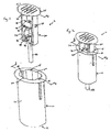
- the preferred retractable sharps assembly 2 comprises a housing 10 and a sharps unit 30.
- the housing 10 has a substantially open end 14 configured to receive the sharps unit 30 as illustrated in Figure 2.
- the housing 10 and the sharps unit 30 will be described in more detail with reference to Figures 3 and 4, respectively.
- the preferred housing 10 comprises a hollow body 12 having the substantially open end 14 and an opposite, generally closed end 16 with an opening 17 therethrough.
- Opposed guide slots 18 are defined along the body 12 to receive guide projections of the sharps unit as will be described hereinafter.
- a second pair of guide slots 20 are also provided for receiving guides provided along the sharps support shelf, as will be described hereinafter.
- the housing 10 may instead be provided with the projections and the corresponding sharps unit 30 components provided with slots or the like.
- it is possible to omit the sharps unit guide slots 18 by configuring the housing opening 14 and the sharps unit frame 32 to correspond, for example, by providing both elements with complementary rectangular configurations.
- the preferred hollow body 12 has a oval configuration, but other shapes, for example, square, rectangular, or circular, can also be used.
- the housing 10 further includes a retaining shoulder 22 and a latch 26, the functions of which will be described hereinafter.
- the preferred sharps unit 30 generally comprises a frame 32, a trigger mechanism 36, a pair of elastic members 44, a sharps carrier defining a sharps support shelf 40 and a sharps member 50.
- the preferred frame 32 has a pair of opposed side ralls 33 extending between a thumb pad 34 and a frame forward end 35.
- a guide projection 38 extends from each rail 33 and is configured to be received within a corresponding housing guide slot 18. Such interaction helps stabilize the sharps unit 30 relative to the housing 10. While this is the preferred frame configuration, other configurations can also be used.
- the trigger mechanism 36 depends from the thumb pad 34 and will be described in more detail hereinafter.
- the sharps member 50 is maintained by the sharps support shelf 40 which is positioned within the frame 32 with the sharps member 50 projecting toward the frame forward end 36.
- the pair of elastic members 44 extend between the frame forward end 35 and the support shelf 40.
- the elastic members 44 are manufactured from an elastic material which can be loaded by both stretching and compression.
- An example of a suitable material is KratonTM G2706 manufactured by Shell 011.
- White the preferred embodiment Includes two elastic members 44, any number of elastic members, including one, may be used.
- the sharps unit 30 is preferably manufactured using a multi-shot injection molding process similar to that described in PCT International Application No. PCT/US99/29541, commonly assigned with the present invention.
- the support shetf's 40 position is maintained by frangible rods 48 extending between it and the rails 33.
- the rods 48 are preferably sufficiently fragile such that the assembly 2 is packaged with the rods 48 intact, but simply break upon depression of the frame 32 during use. However, if desired, the rods 48 may be removed in a post-molding process prior to assembly. In such a case, the support shelf 40 will still be maintained in position as the elastic members 44 are sufficiently rigid to support the shelf 40 away from the frame forward end 35.
- a tapered guide block 42 extends therefrom, as shown in Figure 1.
- the block 42 is configured to be received in and move along the shelf guide slots 20 in the housing 10.
- the support shetf 40 also has a support edge 41 which Will be described hereinafter.
- the preferred sharps unit 30 also includes a removable cap 46 positioned about the forward end of the sharps member 50 and attached to a portion depending from the guide block 42 at a frangible junction 47,
- the cap 46 may also be supported by a pair of frangible rods 48. To remove the cap 46, the cap 46 is twisted or the like to severe the frangible junction 47 and rods 48.
- the sharps unit 30 is positioned in the housing 10 by passing the frame forward end 35 through the opening 14. As the sharps unit 30 moves into the housing 10, the support edge 41 of the support shelf 40 catches and is retained by a projection portion 24 of the shoulder 22. See Figure 6. This is the preferred shipping and storage position of the assembly 2.
- the elastic members 44 are in a relaxed state, while maintaining the sharps member 50 in a position ready for use.
- the assembly 2 preferably includes a cap 46, but such is not necessary. If such is present, it can simply be removed prior to use as explained above.
- a user aligns the housing with the desired target, for example, a finger, and begins depressing the frame 32 by applying pressure to the thumb pad 34 as indicated by the arrows in Figure 7.
- the frangible rods 48 may or may not remain. If the rods 48 are present, they will simply yield to the depression pressure and fracture, thereby allowing the frame 32 to move forward into the housing 10.
- the support edge 41 remains engaged with the shoulder projection 24. As a result, the elastic members 44 are tensioned between the forward moving forward end 35 and the retained shelf 40.
- the trigger mechanism 36 engages the sloped portion 23 of the shoulder 22, proceeds to disengage the projection 24 from the support edge 41, and then engages the underside of the projection 24 to lock the frame 32 within the housing 10.
- the tensioned elastic members 44 cause the support shelf 40, and thereby the sharps member 50, to fire forward, as Indicated by the arrows In Figure 9.
- the sharps member 50 extends from the housing opening 17, thereby engaging the desired target
- the shelf guide slots 20 preferably have a bottom shelf 21, see Figure 9. which defines the limit of forward movement of the support shelf 40 and thereby the sharps member 50.
- the elastic members 44 become compressed. The compressed elastic members 44 thereafter relax, as illustrated in Figure 13, and thereby retract the shelf 40 and sharps member 50 back into the housing 10.
Landscapes
- Health & Medical Sciences (AREA)
- Life Sciences & Earth Sciences (AREA)
- Molecular Biology (AREA)
- Surgery (AREA)
- Biophysics (AREA)
- Pathology (AREA)
- Engineering & Computer Science (AREA)
- Biomedical Technology (AREA)
- Heart & Thoracic Surgery (AREA)
- Medical Informatics (AREA)
- Hematology (AREA)
- Physics & Mathematics (AREA)
- Animal Behavior & Ethology (AREA)
- General Health & Medical Sciences (AREA)
- Public Health (AREA)
- Veterinary Medicine (AREA)
- Dermatology (AREA)
- Infusion, Injection, And Reservoir Apparatuses (AREA)
- Measurement Of The Respiration, Hearing Ability, Form, And Blood Characteristics Of Living Organisms (AREA)
- Details Of Rigid Or Semi-Rigid Containers (AREA)
- Accommodation For Nursing Or Treatment Tables (AREA)
- Supply And Installment Of Electrical Components (AREA)
Claims (4)
- Einziehbares-Scharfteil-Annordnung (2), aufweisend:ein Gehäuse (10), das ein erstes Ende (16) mit einer ersten Öffnung (17) hindurch und eine Schulter (22) im Gehäuse von dem ersten Ende wegweisend aufweist,eine Scharfteil-Einheit (30) mit einem Rahmen (32), der gleitend in das Gehäuse (10) montiert ist, um sich in Richtung zu und weg von dem ersten Ende zu bewegen, einem Triggermechanismus (36), der so befestigt ist, um sich mit dem Rahmen (32) zu bewegen, einem Scharfteil-Halter (40), der derart in den Rahmen (32) montiert ist, dass er in Richtung zu und weg von dem ersten Ende (16) gleiten kann, und der mit der Schulter (22) in Eingriff bringbar ist, einem Scharfteil-Element (50), das befestigt ist, um sich mit dem Scharfteil-Halter (40) zu bewegen, und das sich in Richtung zu der ersten Öffnung erstreckt, und einem elastischen Element (44), das an einem Ende am Rahmen (32) und an dem anderen Ende am Scharfteil-Halter (40) angebracht ist, wobei das Scharfteil-Element (50) im Gehäuse ist bei sich voll in Richtung zum ersten Ende (16) erstreckenden Rahmen (32) und bei entspanntem elastischen Element (44), wobei das elastische Element (44) gespannt ist bei sich im Wesentlichen voll in Richtung zum ersten Ende (16) erstreckenden Rahmen (32) und bei mit der Schulter (22) in Eingriff stehendem Scharfteil-Halter (40), wobei der Triggermechanismus (36) mit dem Scharfteil-Halter (40) in Eingriff kommt bei sich im Wesentlichen voll in Richtung zum ersten Ende (16) erstreckenden Rahmen, um den Scharfteil-Halter (40) von der Schulter (22) auszukuppeln, wobei das Scharfteil-Element (50) bei gespanntem elastischen Element (44) aus dem Gehäuse (10) durch die erste Öffnung (17) ausfahrbar ist, gekennzeichnet dadurch, dass das elastische Element (44) bei sich voll in Richtung zum ersten Ende (16) erstreckenden Rahmen (32) in der Nähe des ersten Endes (16) am Rahmen (32) angebracht ist und dass das elastische Element (44) entfernt von dem ersten Ende (16) am Scharfteil-Halter (40) im Gehäuse (10) angebracht ist.
- Einziehbares-Scharfteil-Annordnung (2) gemäß Anspruch 1, weiter aufweisend:eine Kappe (46), die abnehmbar auf dem Scharfteil-Element (50) angeordnet ist und sich durch die erste Öffnung (17) nach Außen aus dem Gehäuse (10) erstreckt;weiter gekennzeichnet dadurch, dass die Kappe (46) zerbrechlich mit dem Rahmen (32) gekuppelt ist.
- Einziehbares-Scharfteil-Annordnung (2) gemäß Anspruch 1, dadurch gekennzeichnet, dass die Scharfteil-Einheit (30) zerbrechliche Stäbe (48) aufweist, die sich zwischen dem Scharfteil-Halter (40) und dem Rahmen (32) erstrecken.
- Einziehbares-Scharfteil-Annordnung (2) gemäß Anspruch 3, weiter aufweisend:eine Kappe (46), die abnehmbar auf dem Scharfteil-Element (50) angeordnet ist und sich durch die erste Öffnung (17) nach Außen aus dem Gehäuse (10) erstreckt;weiter gekennzeichnet dadurch, dass die Kappe (46) zerbrechlich mit dem Gestell (32) gekuppelt ist.
Applications Claiming Priority (3)
| Application Number | Priority Date | Filing Date | Title |
|---|---|---|---|
| US788932 | 1997-01-24 | ||
| US09/788,932 US6540763B2 (en) | 2001-02-20 | 2001-02-20 | Lancet device with retractable sharps member |
| PCT/SG2002/000025 WO2002065911A1 (en) | 2001-02-20 | 2002-02-19 | Lancet device with retractable sharps member |
Publications (2)
| Publication Number | Publication Date |
|---|---|
| EP1363537A1 EP1363537A1 (de) | 2003-11-26 |
| EP1363537B1 true EP1363537B1 (de) | 2005-07-27 |
Family
ID=25146041
Family Applications (1)
| Application Number | Title | Priority Date | Filing Date |
|---|---|---|---|
| EP02712595A Expired - Lifetime EP1363537B1 (de) | 2001-02-20 | 2002-02-19 | Lanzette mit rückzuganordnung für scharfe gegenstände |
Country Status (6)
| Country | Link |
|---|---|
| US (1) | US6540763B2 (de) |
| EP (1) | EP1363537B1 (de) |
| CN (1) | CN1274277C (de) |
| AT (1) | ATE300239T1 (de) |
| DE (1) | DE60205224T2 (de) |
| WO (1) | WO2002065911A1 (de) |
Families Citing this family (20)
| Publication number | Priority date | Publication date | Assignee | Title |
|---|---|---|---|---|
| US8016847B2 (en) * | 2001-07-11 | 2011-09-13 | Arkray, Inc. | Lancet and lancing apparatus |
| DE10312357B3 (de) * | 2003-03-20 | 2004-07-08 | Roche Diagnostics Gmbh | Stechhilfe und Lanzettensystem mit Wiederverwendungsschutz sowie eine Stechhilfe dafür |
| US7182752B2 (en) | 2003-04-08 | 2007-02-27 | Surgiquest, Incorporated | Continuous gas flow trocar assembly |
| GB0320283D0 (en) * | 2003-08-29 | 2003-10-01 | Owen Mumford Ltd | Improvements relating to lancets |
| US9380975B2 (en) | 2004-05-07 | 2016-07-05 | Becton, Dickinson And Company | Contact activated lancet device |
| CN1968651A (zh) * | 2004-05-07 | 2007-05-23 | 贝克顿·迪金森公司 | 凸轮致动的医疗穿刺装置及方法 |
| PL2135551T3 (pl) * | 2004-05-07 | 2012-03-30 | Becton Dickinson Co | Urządzenie do nakłuwania uruchamiane kontaktowo |
| US9066688B2 (en) * | 2004-05-07 | 2015-06-30 | Becton, Dickinson And Company | Contact activated lancet device |
| WO2006110742A2 (en) | 2005-04-07 | 2006-10-19 | Becton, Dickinson And Company | Lancet device |
| US20070010841A1 (en) * | 2005-07-05 | 2007-01-11 | Medical Innovations Pte Ltd | Lancet assembly |
| US7775991B2 (en) * | 2005-08-31 | 2010-08-17 | Kimberly-Clark Worldwide, Inc. | Device for sampling blood |
| US7927345B2 (en) * | 2006-11-02 | 2011-04-19 | Agamatrix, Inc. | Lancet cartridges and lancing devices |
| AR070764A1 (es) * | 2007-12-07 | 2010-05-05 | Pyng Medical Corp | Aparatos y metodos para introducir portales oseos |
| WO2009129349A2 (en) * | 2008-04-16 | 2009-10-22 | Kim Stanley I | Single-use disposable lancing apparatus and methods |
| US8317812B2 (en) * | 2009-07-29 | 2012-11-27 | Wah Leong Lum | Lancet device with lance retraction |
| USD651713S1 (en) * | 2010-11-16 | 2012-01-03 | Sterilance Medical (Suzhou) Inc. | Pressure activated safety lancet |
| US9999384B2 (en) * | 2011-03-09 | 2018-06-19 | Becton, Dickinson And Company | Sleeve for removable lancet of lancing device |
| ES2812794T3 (es) | 2012-12-05 | 2021-03-18 | Penblade Inc | Dispositivo de corte de seguridad |
| CN106687040B (zh) | 2014-07-18 | 2020-06-09 | 贝克顿·迪金森公司 | 第一滴去除型刺血针装置 |
| CN104665845A (zh) * | 2015-03-10 | 2015-06-03 | 王振民 | 一种上触发一次性安全采血器的改进结构 |
Family Cites Families (23)
| Publication number | Priority date | Publication date | Assignee | Title |
|---|---|---|---|---|
| EP0000862A1 (de) | 1977-08-20 | 1979-03-07 | Passavant-Werke Ag | Bodenentwässerungsrinne für Nassräume |
| US4616649A (en) * | 1984-09-20 | 1986-10-14 | Becton, Dickinson And Company | Lancet |
| US4775369A (en) | 1986-09-09 | 1988-10-04 | Boris Schwartz | Automatically actionable sharpened needle-tip protection |
| US4883068A (en) | 1988-03-14 | 1989-11-28 | Dec In Tech, Inc. | Blood sampling device and method |
| US5086780A (en) | 1990-05-21 | 1992-02-11 | Abbott Laboratories | Blood collection device |
| US5045066A (en) | 1990-06-07 | 1991-09-03 | Smith & Nephew, Inc. | Dental needle with stick resistant protective sleeve |
| US5137521A (en) | 1991-08-19 | 1992-08-11 | Alco Machine & Tool, Inc. | Telescoping safety guard for hypodermic needles and the like |
| CA2123400A1 (en) | 1991-11-12 | 1993-05-27 | Urs A. Ramel | Lancet device |
| US5209739A (en) | 1992-06-23 | 1993-05-11 | Leon Talalay | Hypodermic needle |
| US5336187A (en) | 1993-06-24 | 1994-08-09 | Mark Terry | Automatic cover disposable syringe |
| US5439473A (en) * | 1993-12-13 | 1995-08-08 | Modulohm A/S | Safety lancet |
| JP2723048B2 (ja) | 1994-06-24 | 1998-03-09 | 株式会社ニッショー | 血液吸出器具 |
| US5628765A (en) * | 1994-11-29 | 1997-05-13 | Apls Co., Ltd. | Lancet assembly |
| US5836917A (en) | 1995-01-10 | 1998-11-17 | Specialized Health Products, Inc. | Self retracting medical needle apparatus and methods |
| SE9502285D0 (sv) | 1995-06-22 | 1995-06-22 | Pharmacia Ab | Improvements related to injections |
| US5630803A (en) | 1995-11-06 | 1997-05-20 | Tamaro; Frank A. | Safety cap assembly for needles |
| GB9619462D0 (en) * | 1996-09-18 | 1996-10-30 | Owen Mumford Ltd | Improvements relating to lancet devices |
| US5693023A (en) | 1996-11-15 | 1997-12-02 | Adventec, Inc. | Syringe with retractable needle assembly |
| US5746761A (en) * | 1997-07-03 | 1998-05-05 | Arkadiy Turchin | Disposable lancet for finger/heel stick |
| US6053930A (en) | 1998-05-11 | 2000-04-25 | Ruppert; Norbert | Single use lancet assembly |
| US6258112B1 (en) * | 1999-11-02 | 2001-07-10 | Steven Schraga | Single use lancet assembly |
| DE19959230C1 (de) | 1999-12-08 | 2001-04-05 | Fresenius Medical Care De Gmbh | Vorrichtung zur Durchführung einer medizinischen Behandlung unter Verwendung einer Flüssigkeit sowie ein Disposable für eine derartige Vorrichtung und dessen Verwendung |
| US6248120B1 (en) * | 2000-01-10 | 2001-06-19 | P. Z. “HTL” Spolka Akcyjna | Puncturing device |
-
2001
- 2001-02-20 US US09/788,932 patent/US6540763B2/en not_active Expired - Fee Related
-
2002
- 2002-02-19 WO PCT/SG2002/000025 patent/WO2002065911A1/en not_active Ceased
- 2002-02-19 AT AT02712595T patent/ATE300239T1/de not_active IP Right Cessation
- 2002-02-19 CN CNB028085264A patent/CN1274277C/zh not_active Expired - Fee Related
- 2002-02-19 DE DE60205224T patent/DE60205224T2/de not_active Expired - Fee Related
- 2002-02-19 EP EP02712595A patent/EP1363537B1/de not_active Expired - Lifetime
Also Published As
| Publication number | Publication date |
|---|---|
| CN1274277C (zh) | 2006-09-13 |
| DE60205224D1 (de) | 2005-09-01 |
| EP1363537A1 (de) | 2003-11-26 |
| CN1503646A (zh) | 2004-06-09 |
| US20020128608A1 (en) | 2002-09-12 |
| US6540763B2 (en) | 2003-04-01 |
| DE60205224T2 (de) | 2006-05-24 |
| ATE300239T1 (de) | 2005-08-15 |
| WO2002065911A1 (en) | 2002-08-29 |
Similar Documents
| Publication | Publication Date | Title |
|---|---|---|
| EP1363537B1 (de) | Lanzette mit rückzuganordnung für scharfe gegenstände | |
| US7361160B2 (en) | Injection apparatus comprising a needle-protecting device | |
| US5693023A (en) | Syringe with retractable needle assembly | |
| US5885257A (en) | Spring loaded automatic retractable needle syringe | |
| EP1392379B1 (de) | Schutzhülse für vorgefüllte spritzen | |
| EP0719565B1 (de) | Sicherheitskatheteranordnung mit Sicherheitshaltedruckknopf | |
| US6616639B2 (en) | Safety shield system for syringes | |
| EP2042206B1 (de) | Federaktivierte NadelsicherheitsKlammer | |
| EP1397172B1 (de) | Schutzhülse für vorgefüllte spritzen | |
| AU2002223385B2 (en) | An automatically retractable safety syringe | |
| WO2004060445A2 (en) | Safety system for syringe | |
| US6551288B2 (en) | Safety-sheathed phlebotomy needle holder | |
| EP0317518B1 (de) | Nadelschutzvorrichtung | |
| EP3448461B1 (de) | Haltevorrichtung für ein behältnis in einer medikamentenabgabevorrichtung und medikamentenabgabevorrichtung mit dieser haltevorrichtung | |
| AU2178700A (en) | Syringe with retractable needle assembly | |
| US20240299664A1 (en) | Auto-injector housing latch | |
| WO2001074428A1 (en) | A retractable syringe system | |
| EP1437151B1 (de) | Sicherheitsspritze mit automatischer ausziehbarer Nadel | |
| AU2001243948A1 (en) | A retractable syringe system |
Legal Events
| Date | Code | Title | Description |
|---|---|---|---|
| PUAI | Public reference made under article 153(3) epc to a published international application that has entered the european phase |
Free format text: ORIGINAL CODE: 0009012 |
|
| 17P | Request for examination filed |
Effective date: 20030820 |
|
| AK | Designated contracting states |
Kind code of ref document: A1 Designated state(s): AT BE CH CY DE DK ES FI FR GB GR IE IT LI LU MC NL PT SE TR |
|
| AX | Request for extension of the european patent |
Extension state: AL LT LV MK RO SI |
|
| GRAP | Despatch of communication of intention to grant a patent |
Free format text: ORIGINAL CODE: EPIDOSNIGR1 |
|
| GRAS | Grant fee paid |
Free format text: ORIGINAL CODE: EPIDOSNIGR3 |
|
| GRAA | (expected) grant |
Free format text: ORIGINAL CODE: 0009210 |
|
| AK | Designated contracting states |
Kind code of ref document: B1 Designated state(s): AT BE CH CY DE DK ES FI FR GB GR IE IT LI LU MC NL PT SE TR |
|
| PG25 | Lapsed in a contracting state [announced via postgrant information from national office to epo] |
Ref country code: IT Free format text: LAPSE BECAUSE OF FAILURE TO SUBMIT A TRANSLATION OF THE DESCRIPTION OR TO PAY THE FEE WITHIN THE PRESCRIBED TIME-LIMIT;WARNING: LAPSES OF ITALIAN PATENTS WITH EFFECTIVE DATE BEFORE 2007 MAY HAVE OCCURRED AT ANY TIME BEFORE 2007. THE CORRECT EFFECTIVE DATE MAY BE DIFFERENT FROM THE ONE RECORDED. Effective date: 20050727 Ref country code: FI Free format text: LAPSE BECAUSE OF FAILURE TO SUBMIT A TRANSLATION OF THE DESCRIPTION OR TO PAY THE FEE WITHIN THE PRESCRIBED TIME-LIMIT Effective date: 20050727 Ref country code: BE Free format text: LAPSE BECAUSE OF FAILURE TO SUBMIT A TRANSLATION OF THE DESCRIPTION OR TO PAY THE FEE WITHIN THE PRESCRIBED TIME-LIMIT Effective date: 20050727 Ref country code: NL Free format text: LAPSE BECAUSE OF FAILURE TO SUBMIT A TRANSLATION OF THE DESCRIPTION OR TO PAY THE FEE WITHIN THE PRESCRIBED TIME-LIMIT Effective date: 20050727 Ref country code: CH Free format text: LAPSE BECAUSE OF FAILURE TO SUBMIT A TRANSLATION OF THE DESCRIPTION OR TO PAY THE FEE WITHIN THE PRESCRIBED TIME-LIMIT Effective date: 20050727 Ref country code: AT Free format text: LAPSE BECAUSE OF FAILURE TO SUBMIT A TRANSLATION OF THE DESCRIPTION OR TO PAY THE FEE WITHIN THE PRESCRIBED TIME-LIMIT Effective date: 20050727 Ref country code: TR Free format text: LAPSE BECAUSE OF FAILURE TO SUBMIT A TRANSLATION OF THE DESCRIPTION OR TO PAY THE FEE WITHIN THE PRESCRIBED TIME-LIMIT Effective date: 20050727 Ref country code: LI Free format text: LAPSE BECAUSE OF FAILURE TO SUBMIT A TRANSLATION OF THE DESCRIPTION OR TO PAY THE FEE WITHIN THE PRESCRIBED TIME-LIMIT Effective date: 20050727 |
|
| REG | Reference to a national code |
Ref country code: GB Ref legal event code: FG4D |
|
| RIN1 | Information on inventor provided before grant (corrected) |
Inventor name: MENG, JOHN, TEO, HOCK Inventor name: HIONG, GOH, LIAK |
|
| REG | Reference to a national code |
Ref country code: CH Ref legal event code: EP |
|
| REG | Reference to a national code |
Ref country code: IE Ref legal event code: FG4D |
|
| REF | Corresponds to: |
Ref document number: 60205224 Country of ref document: DE Date of ref document: 20050901 Kind code of ref document: P |
|
| PG25 | Lapsed in a contracting state [announced via postgrant information from national office to epo] |
Ref country code: GR Free format text: LAPSE BECAUSE OF FAILURE TO SUBMIT A TRANSLATION OF THE DESCRIPTION OR TO PAY THE FEE WITHIN THE PRESCRIBED TIME-LIMIT Effective date: 20051027 Ref country code: SE Free format text: LAPSE BECAUSE OF FAILURE TO SUBMIT A TRANSLATION OF THE DESCRIPTION OR TO PAY THE FEE WITHIN THE PRESCRIBED TIME-LIMIT Effective date: 20051027 Ref country code: DK Free format text: LAPSE BECAUSE OF FAILURE TO SUBMIT A TRANSLATION OF THE DESCRIPTION OR TO PAY THE FEE WITHIN THE PRESCRIBED TIME-LIMIT Effective date: 20051027 |
|
| PG25 | Lapsed in a contracting state [announced via postgrant information from national office to epo] |
Ref country code: PT Free format text: LAPSE BECAUSE OF FAILURE TO SUBMIT A TRANSLATION OF THE DESCRIPTION OR TO PAY THE FEE WITHIN THE PRESCRIBED TIME-LIMIT Effective date: 20051227 |
|
| RAP2 | Party data changed (patent owner data changed or rights of a patent transferred) |
Owner name: FUTUMEDS SDN. BHD |
|
| REG | Reference to a national code |
Ref country code: CH Ref legal event code: PL |
|
| NLV1 | Nl: lapsed or annulled due to failure to fulfill the requirements of art. 29p and 29m of the patents act | ||
| REG | Reference to a national code |
Ref country code: GB Ref legal event code: 732E |
|
| PGFP | Annual fee paid to national office [announced via postgrant information from national office to epo] |
Ref country code: GB Payment date: 20060207 Year of fee payment: 5 |
|
| PG25 | Lapsed in a contracting state [announced via postgrant information from national office to epo] |
Ref country code: IE Free format text: LAPSE BECAUSE OF NON-PAYMENT OF DUE FEES Effective date: 20060220 |
|
| PGFP | Annual fee paid to national office [announced via postgrant information from national office to epo] |
Ref country code: FR Payment date: 20060224 Year of fee payment: 5 |
|
| PG25 | Lapsed in a contracting state [announced via postgrant information from national office to epo] |
Ref country code: LU Free format text: LAPSE BECAUSE OF NON-PAYMENT OF DUE FEES Effective date: 20060228 Ref country code: MC Free format text: LAPSE BECAUSE OF NON-PAYMENT OF DUE FEES Effective date: 20060228 |
|
| PGFP | Annual fee paid to national office [announced via postgrant information from national office to epo] |
Ref country code: DE Payment date: 20060228 Year of fee payment: 5 |
|
| ET | Fr: translation filed | ||
| PLBE | No opposition filed within time limit |
Free format text: ORIGINAL CODE: 0009261 |
|
| STAA | Information on the status of an ep patent application or granted ep patent |
Free format text: STATUS: NO OPPOSITION FILED WITHIN TIME LIMIT |
|
| 26N | No opposition filed |
Effective date: 20060428 |
|
| REG | Reference to a national code |
Ref country code: IE Ref legal event code: MM4A |
|
| GBPC | Gb: european patent ceased through non-payment of renewal fee |
Effective date: 20070219 |
|
| REG | Reference to a national code |
Ref country code: FR Ref legal event code: ST Effective date: 20071030 |
|
| PG25 | Lapsed in a contracting state [announced via postgrant information from national office to epo] |
Ref country code: DE Free format text: LAPSE BECAUSE OF NON-PAYMENT OF DUE FEES Effective date: 20070901 |
|
| PG25 | Lapsed in a contracting state [announced via postgrant information from national office to epo] |
Ref country code: FR Free format text: LAPSE BECAUSE OF NON-PAYMENT OF DUE FEES Effective date: 20070228 Ref country code: GB Free format text: LAPSE BECAUSE OF NON-PAYMENT OF DUE FEES Effective date: 20070219 |
|
| PG25 | Lapsed in a contracting state [announced via postgrant information from national office to epo] |
Ref country code: CY Free format text: LAPSE BECAUSE OF FAILURE TO SUBMIT A TRANSLATION OF THE DESCRIPTION OR TO PAY THE FEE WITHIN THE PRESCRIBED TIME-LIMIT Effective date: 20050727 |
|
| PG25 | Lapsed in a contracting state [announced via postgrant information from national office to epo] |
Ref country code: ES Free format text: LAPSE BECAUSE OF NON-PAYMENT OF DUE FEES Effective date: 20060228 |