EP1363397A2 - Cascaded surface acoustic wave filter system for cancelling time spurious responses - Google Patents
Cascaded surface acoustic wave filter system for cancelling time spurious responses Download PDFInfo
- Publication number
- EP1363397A2 EP1363397A2 EP03010930A EP03010930A EP1363397A2 EP 1363397 A2 EP1363397 A2 EP 1363397A2 EP 03010930 A EP03010930 A EP 03010930A EP 03010930 A EP03010930 A EP 03010930A EP 1363397 A2 EP1363397 A2 EP 1363397A2
- Authority
- EP
- European Patent Office
- Prior art keywords
- filter
- input
- acoustic wave
- surface acoustic
- transducer
- Prior art date
- Legal status (The legal status is an assumption and is not a legal conclusion. Google has not performed a legal analysis and makes no representation as to the accuracy of the status listed.)
- Withdrawn
Links
- 238000010897 surface acoustic wave method Methods 0.000 title claims description 193
- 239000000758 substrate Substances 0.000 claims abstract description 29
- 230000001629 suppression Effects 0.000 claims description 19
- 238000004891 communication Methods 0.000 claims description 14
- 239000000463 material Substances 0.000 claims description 12
- 238000003780 insertion Methods 0.000 claims description 6
- 230000037431 insertion Effects 0.000 claims description 6
- 238000005070 sampling Methods 0.000 claims description 3
- 230000001934 delay Effects 0.000 claims 1
- 230000002401 inhibitory effect Effects 0.000 claims 1
- 238000000034 method Methods 0.000 description 17
- 238000002592 echocardiography Methods 0.000 description 11
- 239000006098 acoustic absorber Substances 0.000 description 5
- 238000013459 approach Methods 0.000 description 5
- 230000008878 coupling Effects 0.000 description 4
- 238000010168 coupling process Methods 0.000 description 4
- 238000005859 coupling reaction Methods 0.000 description 4
- 238000010586 diagram Methods 0.000 description 4
- 230000000694 effects Effects 0.000 description 4
- GQYHUHYESMUTHG-UHFFFAOYSA-N lithium niobate Chemical compound [Li+].[O-][Nb](=O)=O GQYHUHYESMUTHG-UHFFFAOYSA-N 0.000 description 4
- 238000000926 separation method Methods 0.000 description 4
- 230000008901 benefit Effects 0.000 description 3
- 230000015556 catabolic process Effects 0.000 description 3
- 238000006731 degradation reaction Methods 0.000 description 3
- 230000005540 biological transmission Effects 0.000 description 2
- 238000007796 conventional method Methods 0.000 description 2
- 238000013461 design Methods 0.000 description 2
- 230000005684 electric field Effects 0.000 description 2
- 238000005530 etching Methods 0.000 description 2
- 229910052751 metal Inorganic materials 0.000 description 2
- 239000002184 metal Substances 0.000 description 2
- WSMQKESQZFQMFW-UHFFFAOYSA-N 5-methyl-pyrazole-3-carboxylic acid Chemical compound CC1=CC(C(O)=O)=NN1 WSMQKESQZFQMFW-UHFFFAOYSA-N 0.000 description 1
- 229910000838 Al alloy Inorganic materials 0.000 description 1
- VYZAMTAEIAYCRO-UHFFFAOYSA-N Chromium Chemical compound [Cr] VYZAMTAEIAYCRO-UHFFFAOYSA-N 0.000 description 1
- RTAQQCXQSZGOHL-UHFFFAOYSA-N Titanium Chemical compound [Ti] RTAQQCXQSZGOHL-UHFFFAOYSA-N 0.000 description 1
- 230000002411 adverse Effects 0.000 description 1
- 229910052782 aluminium Inorganic materials 0.000 description 1
- XAGFODPZIPBFFR-UHFFFAOYSA-N aluminium Chemical compound [Al] XAGFODPZIPBFFR-UHFFFAOYSA-N 0.000 description 1
- 239000003990 capacitor Substances 0.000 description 1
- 229910052804 chromium Inorganic materials 0.000 description 1
- 239000011651 chromium Substances 0.000 description 1
- 230000007423 decrease Effects 0.000 description 1
- 238000000151 deposition Methods 0.000 description 1
- 238000009795 derivation Methods 0.000 description 1
- 230000008030 elimination Effects 0.000 description 1
- 238000003379 elimination reaction Methods 0.000 description 1
- 230000005284 excitation Effects 0.000 description 1
- 238000001914 filtration Methods 0.000 description 1
- PCHJSUWPFVWCPO-UHFFFAOYSA-N gold Chemical compound [Au] PCHJSUWPFVWCPO-UHFFFAOYSA-N 0.000 description 1
- 229910052737 gold Inorganic materials 0.000 description 1
- 239000010931 gold Substances 0.000 description 1
- 238000004519 manufacturing process Methods 0.000 description 1
- 230000000737 periodic effect Effects 0.000 description 1
- 239000010453 quartz Substances 0.000 description 1
- 230000008929 regeneration Effects 0.000 description 1
- 238000011069 regeneration method Methods 0.000 description 1
- VYPSYNLAJGMNEJ-UHFFFAOYSA-N silicon dioxide Inorganic materials O=[Si]=O VYPSYNLAJGMNEJ-UHFFFAOYSA-N 0.000 description 1
- 239000010936 titanium Substances 0.000 description 1
- 229910052719 titanium Inorganic materials 0.000 description 1
Images




Classifications
-
- H—ELECTRICITY
- H03—ELECTRONIC CIRCUITRY
- H03H—IMPEDANCE NETWORKS, e.g. RESONANT CIRCUITS; RESONATORS
- H03H9/00—Networks comprising electromechanical or electro-acoustic elements; Electromechanical resonators
- H03H9/46—Filters
- H03H9/64—Filters using surface acoustic waves
- H03H9/6489—Compensation of undesirable effects
Definitions
- This invention relates generally to Surface Acoustic Wave (SAW) filters and, more particularly, to the elimination of undesirable time spurious signals such as electromagnetic feedthrough and acoustic echoes in SAW filters.
- SAW Surface Acoustic Wave
- Triple transit echoes and electromagnetic feedthrough associated with SAW filters represent well-known problems in the design of communications systems.
- Triple transit echoes are produced when the acoustic wave generated by an input transducer is first reflected and regenerated by the output transducer, and then is again reflected and regenerated by the input transducer.
- regenerations and reflections of the SAW back and forth between the input and output transducers result in fifth, seventh and higher order transit echoes in addition to triple transit echoes.
- the resulting echoes degrade filter performance by creating both group delay and pass band ripples.
- Single phase, two-phase, three-phase and four-phase unidirectional transducers are often used to reduce the effects of triple transit echoes.
- Single-phase unidirectional transducers SPUDT
- DART Distributed Acoustic Reflection Transducer
- EWC Electrode Width Controlled
- GSPUDT Group SPUDT
- DSPUDT Dithered SPUDT
- SPUDT SAW filters are widely used in mobile phone and satellite communications systems because of their superior channel selectivity and relatively low insertion loss.
- SPUDT filter performance depends heavily on the stability of the matching circuits. Therefore, decreases in triple transit suppression (TTS), and increases in group delay and pass band ripples due to matching component (resistor, inductor and capacitor) value variations and temperature-induced mismatch in the matching circuits adversely affects the performance of such filters. It can also be labor intensive to fine-tune the matching circuits in order to meet the requirements for the high performance SAW filters used in satellite communications.
- TTS triple transit suppression
- the feedthrough is an undesired signal that degrades filter performance by creating both group delay and pass band ripples in the pass band, and that reduces the ultimate rejection outside the pass band regions in the frequency domain. The problem becomes very prominent for high frequency SAW filters since the input and output transducers and the input and output matching circuits are placed much closer to each other since the filter geometry is inversely proportional to the operating frequency.
- Methods 3) and 4) are simple to implement; however, the feedthrough cannot be fully suppressed, especially when the operating frequency is high.
- Methods 1) and 2) are more effective methods for reducing feedthrough; however, these methods increase the overall cost of the filter package and the complexity of the matching circuits.
- the cascaded feedthrough level will be 6 dB worse than the feedthrough suppression of each individual filter. This degradation in feedthrough suppression becomes problematic in the above-discussed satellite and mobile phone applications in which feedthrough suppression is crucial.
- spur suppression will be 6 dB worse than the spur suppression of each individual filter. This degradation in spur suppression becomes problematic in the above-discussed satellite and mobile phone applications in which spur suppression is crucial.
- the present invention provides a cascaded SAW filter system in which two SAW filters are electrically cascaded in series to cancel time spurious signals.
- the first filter consists of one input transducer and one output transducer built on a piezoelectric substrate.
- a perturbation region may or may be not present between the two transducers of the first filter.
- the m th transit echo (where m is an odd number greater than 1) or feedthrough associated with the first filter is at a time TD (TD will be negative for the case of feedthrough) away from the main response in the time domain and has an associated frequency response with a center frequency fo.
- the second filter consists of one input transducer and one output transducer built on a piezoelectric substrate that can be the same, or different, type of material as that of the first filter, and that can be fabricated either on the same substrate as that of the first filter or on a separate substrate.
- a perturbation region may or may be not present between the two transducers of the second filter.
- the m th transit echo or feedthrough associated with the second filter is at a time TD' (TD' will be negative for the case of feedthrough) away from the main response in the time domain, and has an associated frequency response with a center frequency fo' that is similar to, but typically slightly offset from, the center frequency fo of the first filter.
- the associated time spur of the cascaded response will also be canceled.
- a similar technique can be used to cancel the reflections at the ends of the transducers by adding extra dummy fingers at the ends of the transducers of the second filter so that the edges of the transducers of the second filter are approximately (n+1/2) ⁇ /2 from the respective edges of the transducers of the first filter.
- FIG. 1 shows an exemplary satellite communications system 10 in which a cascaded surface acoustic wave filter system (SAW filter system) 12 including SAW filters 12a, 12b, according to a preferred embodiment of the present invention is implemented.
- the satellite communications system 10 which may be any satellite deployed for commercial or military communications purposes, includes an antenna 14 for receiving and transmitting a signal in a predetermined operating frequency such as an RF signal.
- a high frequency front-end filter 16 filters unwanted signal portions including transients and noise from the signal prior to the signal being amplified by a low noise amplifier (LNA) 18.
- LNA low noise amplifier
- the amplified signal output from the LNA 18 is then mixed at a mixer 20 with a single tone-oscillating signal generated by an oscillator (VCO) 22.
- the resulting signal output from the mixer 20 is an IF signal that is input into an amplifier 24.
- the amplifier 24 amplifies the IF signal to a required input level of the SAW filter 12a.
- the SAW filter 12a then filters the signal in a manner that will be discussed below.
- a SAW filter system buffer such as a variable gain amplifier (VGA) 26, prevents distortion of the IF signal as the IF signal is output from the SAW filter 12a and input into the SAW filter 12b.
- this buffer may be a component other than the VGA 26.
- some type of buffer between the SAW filters 12a, 12b is desirable in order to electrically isolate the SAW filters 12a, 12b from one another and thereby prevent signal distortion.
- the VGA 26 adjusts the signal level of the IF signal to an input level of the SAW filter 12b.
- An amplifier 28 amplifies the IF signal output from the SAW filter 12b, and a lowpass filter 30 filters out high frequency noise that the SAW filters 12a, 12b are not capable of filtering from the IF signal.
- An amplifier 32 amplifies the IF signal to an input level of an A/D converter 34. The A/D converter 34 then converts the signal to a digital signal so that the signal can be further processed by other system components.
- the SAW filter system 12 will be discussed with reference to its implementation in the satellite communications system 10 throughout the present specification for purposes of illustration and discussion, the SAW filter system 12 may be implemented in any communications-related environment, such as, for example, a wireless communications base station, as well as any other environment in which surface acoustic waves are generated and transmitted, to cancel time spurs and therefore the associated pass band and group delay ripples.
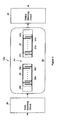
- FIG. 2 shows in more detail the structure of the SAW filter 12a, with it being understood that the structure of the SAW filter 12b is essentially the same as that of the SAW filter 12a, and that the filter topology shown is just one example of transducer topology and is used here only for purposes of illustration and discussion.
- the SAW filter 12a includes an input transducer 36 and an output transducer 37 mounted on a piezoelectric substrate 38 and positioned between input and output matching circuits 39, 40.
- a perturbation region P1 is positioned between the input transducer 36 and the output transducer 37.
- the input and output transducers 36, 37 are preferably formed from, for example, aluminum, aluminum alloy, gold, titanium, chromium or the like, and are spaced apart from one another on the substrate 38 according to the transmission characteristics of the surface acoustic wave to be transmitted therebetween.
- the input and output transducers 36, 37 include interdigital fingers (fingers) 36a, 37a. One group of the fingers 36a is electrically connected to a common bus bar or electrode 36c, and another group of the fingers 36a is electrically connected to a common bus bar or electrode 36c', for electrical conduction.
- one group of the fingers 37a is electrically connected to a common bus bar or electrode 37c, while another group of the fingers 37a is electrically connected to a common bus bar or electrode 37c', for electrical conduction.
- a two phase, three phase or four phase unidirectional transducer has more than two bus bars.
- one or both of the input or output transducers 36, 37 may consist of more than one sub-transducer connected in series, or in parallel, or a combination of series and parallel, with each such sub-transducer having a configuration that is similar to the input and output transducers 36, 37.
- Acoustic absorbers 36b, 37b are usually placed near the respective ends of the input and output transducers 36, 37 for absorbing unwanted acoustic energy leaking toward the respective ends.
- perturbation regions P1, P2 can be implemented in a number of ways as shown in FIGs. 3A - 3G.
- the SAW propagation velocity vp in the perturbation region P1 of the SAW filter 12a is different from the free surface velocity v.
- the width Y of the perturbation region P1 should be greater than the height w of the input and output transducers 36, 37.
- the transducer aperture and edge E1 is in general but not necessarily always parallel to the edge E2 at least over the transducer aperture, and the edges E1, E2 do not have to be parallel to the transducer fingers 36a.
- the same structural parameters also apply to the SAW filter 12b.
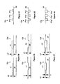
- the perturbation regions P1, P2 can be formed as metallized surfaces having respective thicknesses h1, h1' using the same, or different, material as that used to form the transducer fingers 36a, 37a. Therefore, if the thickness h1 of the perturbation region P1 is different from the thickness h1' of the perturbation region P2, v p will be different from v p' . As shown in FIG. 3C, the perturbation region P1 and/or the perturbation region P2 can be sub-divided into more than one section as represented by the sections P1a, P1b, P1c.
- perturbation regions P1', P2' of SAW filters 12a', 12b' can be formed as recessed surfaces by etching the substrate surfaces 38, 38' to respective depths t1, t1'. Therefore, if the depth t1 of the perturbation region P1' is different from the depth t1' of the perturbation region P2', v p will be different from v p' . As shown in FIG. 3E, the perturbation region P1' and/or the perturbation region P2' can be sub-divided into more than one section as represented by the sections P1a', P1b', P1c'.
- perturbation regions P1", P2" can be formed by depositing metal with respective thicknesses h1, h1' in recessed surfaces created by etching the substrate surfaces 38, 38' to respective depths t1, t1'. Therefore, if the depth t1 of the perturbation region P1 is different from the depth t1' of the perturbation region P2 and/or the thickness h1 is different from the thickness h1', v p will be different from v p' . As shown in FIG. 3G, the perturbation region P1 and/or the perturbation region P2 can be sub-divided into more than one section as represented by the sections P1a", P1b", P1c".
- the substrate 38 is a piezoelectric material such as quartz, lithium tantalate, lithium niobate or the like.
- the input and output matching circuits 39, 40 each include one or more RLC components to match the impedance of the SAW filter 12a to the impedance, or loading, of the rest of the satellite communications system 10 or other system in which the SAW filter 12a (as well as the SAW filter 12b) is implemented.
- the input transducer 36 is for receiving an input AC signal, such as the IF signal discussed above, and for generating an electrical field in a gap defined between the input transducer fingers 36a due to excitation of the fingers 36a by the AC signal.
- the electrical field is then converted by the input transducer 36 into a mechanical perturbation, or SAW, that propagates across the substrate 38.
- SAW mechanical perturbation
- Part of the SAW propagate away from the output transducer 37 and is absorbed by the acoustic absorber 36b.
- the rest of the SAW propagates to the output transducer 37 through the perturbation region P1.
- the output transducer 37 receives the SAW and converts it back to an AC signal in a manner opposite that described in connection with the input transducer 36.
- only certain frequencies of the signal input into the input transducer 36 are transmitted to the output transducer 37 depending upon the resonant structure of the input and output transducers 36, 37.
- the perturbation region P1 is excluded from the picture to simplify the explanation.
- the SAW propagates to an output transducer 44 with an acoustic absorber 45 across a piezoelectric substrate 46. This propagation consequently results in the generation and propagation of spurious responses, or time spurs, such as regenerated waves 54, 56, second regenerated waves 58, 60, and regenerated waves 62, 64.
- the regenerated waves 54, 56 are typically two of the more challenging spurs to eliminate and are very strong spurs if a SAW filter is built on a substrate formed from a strong coupling material such as lithium niobate.
- a triple transit echo is generated as indicated at 66 and feedthrough 68 near zero seconds in propagation time are universal for all SAW filters constructed in a manner similar to the SAW filter 41.
- FIG. 3A shows the spacing of the input transducers 36, 36', output transducers 37, 37' and perturbation regions P1, P2 of SAW filters 12a, 12b relative to one another.
- the SAW filter 12b includes input and output transducers 36', 37' mounted on a substrate 38' formed from either the same, or a different, type of piezoelectric material than the substrate 38.
- the SAW filter 12b can be fabricated either on the same substrate as that of the SAW filter 12a or on a separate substrate.
- ⁇ v/f 0
- v the propagation velocity of the surface acoustic wave on the substrates 38, 38'
- f 0 the center frequency of the SAW filters 12a, 12b.
- the center lines 70', 72' of the input and output transducers 36', 37' can be adjusted by, for example, adjusting the layout of a mask used to form the input and output transducers 36', 37' during fabrication.
- the respective pass band ripples, group delay ripples and the associated time spur associated with the filters 12a, 12b can be made to cancel one another.
- the time spur can be the m th transit echo or feedthrough.
- a time spur 74 associated with the filter 12a is spaced a distance TD apart from a direct SAW 76 in the time domain.
- a time spur 82 that is similar to the time spur 74 associated with the SAW filter 12b is at a spaced distance TD' apart from a main response 84 in the time domain.
- FIG. 8B which graphically shows the Fourier Transform of the function h'(t)
- a pass band ripple 86 with magnitude P' and an associated group delay ripple 88 with magnitude G' are offset from the pass band ripple 78 and the group delay ripple 80 associated with the SAW filter 12a by 180°.
- the pass band ripples 78, 86 cancel one another and the group delay ripples 80, 88 cancel one another, leaving only the desired frequency response 90.
- the time spurs 74 and 82 are on the right hand side of the main signals 76 and 84, respectively, the same cancellation principle will also apply if the time spurs 74 and 82 are on the left side of the main signals 76 and 84, respectively.
- the triple transit echo of the cascaded response will also be canceled.
- the path length difference between the triple transit echo 66 and the direct surface acoustic wave 52 is 2L.
- the time spur of interest is the m th transit echo where m is an odd integer and is greater than 1
- the SAW filter system cancels the group delay and pass band ripples generated by the SAW filters 12a, 12b in the manner described above
- other embodiments of the present invention may also be implemented to cancel the group delay and pass band ripples.
- the center frequency f 0 can be changed by changing the geometry of the fingers 36a, 37a of the input and output transducers 36, 37 of the filter 12a. Specifically, the horizontal dimensions or the finger width and finger gap of the fingers 36a, 37a can be changed to change the wavelength of the waves generated by the fingers 36a, 37a. Also, the vertical dimensions, or metal thicknesses, of the fingers 36a, 37a can be changed to change the propagation velocity vf of waves generated by the fingers 36a, 37a. Alternatively, the substrate 38 of the SAW filter 12a can be changed to alter the propagation velocity associated with the SAW filter 12a. Of course, any combination of the above techniques may be used to adjust the center frequency f 0 , and the above techniques are equally applicable to the SAW filter 12b as well.
- a hybrid of the preceding two embodiments may be designed to cancel the group delay and pass band ripples and consequently the associated time spur associated with the SAW filters 12a, 12b.
- the SAW filter system 12 may be designed in a manner similar to that of the two above-described embodiments, so that by both spacing of the input transducers 36, 36' by a predetermined fraction of the SAW wavelength, and by offsetting the center frequency f 0 ' associated with the SAW filter 12a' with respect to the center frequency f 0 of the SAW filter 12a, cancellation of group delay and pass band ripples and of the associated time spur.
- a perturbation regions P1, P2 can be fabricated between the input and output transducers 36, 37 of the SAW filter 12a and between the input and output transducers 36', 37' of the SAW filter 12b, respectively, to cancel the group delay and pass band ripples and consequently the associated time spur associated with the SAW filters 12a, 12b.
- the perturbation region P1 provides a media for the SAW to travel with a different velocity vp from the free surface velocity v.
- the TD and TD' of the SAW filters 12a, 12b can be adjusted to satisfy the condition for time spur cancellation as mentioned above.
- Eq. (1) is just several techniques for effecting time spur cancellation. According to Eq. (1) below, many combinations of the above methods may be used to cancel time spurs. Using different combinations involves changing one or more parameters in Eq. (1) so that (TD-TD') satisfies the condition (n+1/2) ⁇ /(m-1) for time spur cancellation. Referring back to FIG. 3A, changing the parameters x1 and/or x5 so that x1 ⁇ > x1' and /or x5 ⁇ >x5' is equivalent to changing input transducer and/ or output transducer design so that the input transducer 36 is not the same as the input transducer 36' and/or so that the output transducer 37 is not the same as the output transducer 37'.
- Changing the parameters x2 and/or x4 so that x2 ⁇ > x2' and /or x4 ⁇ >x4' is equivalent to changing the input and output transducer offset so that L ⁇ > L'.
- Changing x3 and/or vp so that x3 ⁇ >x3' and/or vp ⁇ >vp' is equivalent to changing the perturbation region so that P1 is not the same as P2.
- Changing vm so that vm ⁇ >vm' is equivalent to changing the center frequency of the input transducers 36, 36' and the output transducers 37, 37' so that fo ⁇ >fo'.
- Changing v so that v ⁇ >v' is equivalent to using a different material for the SAW filter 12b.
- T T is used to distinguish TD since TD is the separation between the main signal and time spur
- T' the time delay for the main SAW signal to travel from L1' to L2' for the SAW filter 12b.
- T (x1+x5)/vm + (x2+x4)/v + x3/vp for the SAW filter 12a.
- T (x1'+x5')/vm' + (x2'+x4')/v' + x3'/vp' for the SAW filter 12b
- vm is the SAW propagation velocity in the transducers of the SAW filter 12a
- vm' is the SAW propagation velocity in the transducers of the SAW filter 12b
- v is the SAW propagation velocity in the free surface of filter 12a
- v' is the SAW propagation velocity in the free surface of the SAW filter 12b
- vp is the SAW propagation velocity in the perturbation region P1 of the SAW filter 12a
- vp' is the SAW propagation velocity in the perturbation region P2 of the SAW filter 12b.
- T-T' [(x1+x5)/vm-(x1'+x5')/vm'] + [(x2+x4)/v-(x2'+x4)/v'] + (x3/vp-x3'/vp')
- T-T' in Eq. (2) is a function of the spacing between the input and output transducers 36, 37 and 36', 37', and it is independent of the perturbation regions as long as the perturbation region P1 is identical to the perturbation region P2.
- Eq. 7 shows that (T-T') is a function of x2, x3, x4 and vp of the SAW filter 12a, and x2', x3', x4' and vp' of the SAW filter 12b.
- vp and vp' can be set to different values by changing the physical geometry of the perturbation regions P1 and P2 as shown in FIG. 2.
- FIGs. 3B - 3F are cross-section views of perturbation regions P1 and P2 along the lines III-III and III'-III' in FIG. 2, respectively. They show different ways of implementing the perturbation regions P1, P2.
- FIGs. 3B, 3D and 3F show that vp can be changed by changing the corresponding vertical dimensions indicated in each figure.
- FIGs. 3C, 3E and 3G show that the perturbation region P1 can be sub-divided into more than one section, with each subsection being either periodic or aperiodic with respect to the other subsections.
- FIG. 9 shows the benefits of implementing the SAW filter system according to the above embodiments of the present invention. Specifically, the filter output resulting from two identical filters being cascaded according to a conventional technique are shown at 92, while the filter output of the SAW filter system of the present invention is shown at 94. As shown, triple transit suppression was only 50 dB using the conventional cascading technique, while triple transit suppression was increased to 63 dB by using the SAW filter system of the present invention.
- FIG. 10 shows another embodiment of the present invention that is particularly useful when implemented in a SAW filter built on a substrate formed from strong coupling material such as lithium niobate.
- input and output transducers 136a, 137a of a SAW filter 112b are shown with the input and output transducers 36a, 37a of the SAW filter 12a.
- the input and output transducers 136a, 137a include dummy fingers 138a, 139a at each respective end thereof.
- the path length difference between regenerated wave 54 and the direct surface acoustic wave 52 is 2X.
- the path length difference between the regenerated wave or spur 56 and the direct surface acoustic wave 52 is 2Y.
- a dummy finger 138b can be added to the left end of the input transducer 136a, and the dummy finger 139b can be added to the right side of the output transducer 137a in the same manner as described above for edge reflection cancellation.
- the transducer sampling rate is four fingers per ⁇ , then (2n+1) dummy fingers spaced ⁇ /4 apart from each other can be added to the respective ends of the filter 112b for edge reflection cancellation.
- the edge reflection cancellations can also be achieved by adding a number of dummy fingers at the ends of the input and output transducers 136, 137 of the filter 112b so that the offset of the edges of the transducers between the filters 12a, 112b is approximately (n+1/2) ⁇ /2.
- the SAW filter system according to the preferred embodiments of the present invention is advantageous over conventional SAW filters for several reasons.
- the SAW filter system of the present invention is extremely simple to implement.
- triple transit suppression can be easily achieved by offsetting the input and output transducers of the two filters by ⁇ /4, or by offsetting the center frequencies of the filters by 1/(2TD), where TD is the separation between the main signal and triple transit echo.
- Similar suppression can also be done to feedthrough spur or higher order transit echoes by using the similar offset approach, depending on which spur is the dominant one that degrades the overall performance. If this approach is used properly, one spur can be totally cancelled while one or more other spurs can be partially suppressed.
- the dummy finger approach and the offset approach can be incorporated into the SAW filter system to cancel both the edge reflections and the other time spurs mentioned above.
- the SAW filter system eliminates the intrinsic problem associated with cascading two identical filters; that is, the group delay and pass band ripples almost double and associated time spur suppression is 6 dB worse after cascading two identical filters. Since the group delay and pass band ripple responses of the first filter are always 180° out of phase with respect to those of the second filter, the cascaded ripples are less than the ripples of the individual response due to the above-discussed ripple cancellation associated with the present invention. In other words, the SAW filter system of the present invention further suppresses the cascaded time spur when compared to conventional suppression techniques without needing to be overdesigned to reduce the group delay and pass band ripples.
- the SAW filter system of the present invention is less sensitive to matching circuit component variations due to temperature change or component tolerances, thereby resulting in a more consistent cancellation of the group delay and pass band ripples and the triple transit spur.
- the SAW filter system of the present invention can also be implemented with less costly filters, as there is no need to fine tune the filter responses in order to meet the tight ripple or triple transit spur requirements as in conventional SAW filter implementations. Further, because the SAW filter system of the present invention can tolerate a higher triple transit spur associated with individual filters used in the system, the insertion loss of the filter system can be improved.
- the SAW filter system of the present invention can be implemented using filters with a wide range of fractional bandwidth.
- the SAW filter system of the present invention works best when filters having narrow fractional bandwidth are used.
- experimental data has shown that the SAW filter system of the present invention implemented with filters having 23% fractional bandwidth still is capable of canceling group delay and pass band ripples.
- the SAW filter system of the present invention also provides a simple solution regarding cancellation of transducer edge reflections that become problematic for filter systems implemented on substrates composed of strong coupling materials by adding dummy fingers to input and output transducer ends.
- SAW filter system of the present invention may be implemented using any type of transversal SAW filter pair in cascade.
- SPUDT filters may preferably be used to implement the present invention because the triple transit echo associated with an individual SPUDT filter is initially small.
- the separations in time between the feedthrough spur and the main wave are also different for the individual filters. If the offset approach is mainly used to cancel the triple transit echo, the cascaded feedthrough suppression will not be degraded by 6 dB as with two identical cascaded filters because feedthrough spurs of the cascaded offset filters have partial offset.
Landscapes
- Physics & Mathematics (AREA)
- Acoustics & Sound (AREA)
- Surface Acoustic Wave Elements And Circuit Networks Thereof (AREA)
Abstract
Description
Claims (10)
- A surface acoustic wave filter system (12) comprising:characterized in thata first filter (12a) including a first piezoelectric substrate (38), a first input transducer (36) on the first piezoelectric substrate for generating and transmitting a first surface acoustic wave having a predetermined wavelength λ from an input electrical signal having a predetermined frequency, and a first output transducer (37) for receiving and converting the first surface acoustic wave to a first filtered electrical signal;a second filter (12b) cascaded in series with the first filter and including a second piezoelectric substrate (38'), a second input transducer (36') for generating and transmitting a second surface acoustic wave from'the first filtered electrical signal, and a second output transducer (37') for receiving and converting the second surface acoustic wave to a second filtered electrical signal;
the first input transducer of the first filter is separated from the second input transducer of the second filter by a distance of (n + 1/2)λ/(m-1), where n is an integer greater than or equal to 0, and m is either 2 if the time spur is feedthrough or an odd integer greater than 1 if the time spur is the mth transit echo; and/or
a center frequency fO' of the second filter is offset from a center frequency fO of the first filter as follows: fO = fO' + (n + 1/2)F, where n is an integer greater than or equal to 0, and F is the predetermined frequency of the input electrical signal and the filtered electrical signal;
to enhance system time spur suppression. - The surface acoustic wave filter system according to claim 1, wherein the first input transducer of the first filter is separated from the second input transducer of the second filter to enhance the system time spur suppression by more than 20 dB.
- The surface acoustic wave filter system according to any of the foregoing claims, further comprising at least one dummy finger (138a; 138b; 139a; 139b) at at least one end of each of the first input and output transducers and the second input and output transducers for inhibiting edge reflections.
- The surface acoustic wave filter system of claim 3, wherein the at least one dummy finger comprises (2n+1) dummy fingers spaced λ/4 apart from each other at respective ends of the first and second input and output transducers when a transducer sampling rate is four fingers per λ.
- The surface acoustic wave filter system according to any of the foregoing claims, wherein the first and second piezoelectric substrates are formed from an identical piezoelectric material.
- The surface acoustic wave filter system according to any of the foregoing claims, wherein the first and second piezoelectric substrates are formed from different piezoelectric materials.
- The surface acoustic wave filter system according to any of the foregoing claims, wherein the first input transducer of the first filter is separated from the second input transducer of the second filter to further provide a system insertion loss that is less than an insertion loss associated with a surface acoustic wave filter system comprising two identical filters in cascade.
- The surface acoustic wave filter system according to any of the foregoing claims, further comprising: an input matching circuit (39) in electrical communication with the first input transducer of the first filter and an output matching circuit (40) in electrical communication with the second output transducer of the second filter, wherein each of the input and output matching circuits comprises one or more RLC components for matching respective impedances of the first and second filters to a surrounding system impedance.
- The surface acoustic wave filter system according to any of the foregoing claims, wherein each of the first and second filters comprises a SPUDT surface acoustic wave filter.
- A surface acoustic wave filter system according to any of the foregoing claims, further comprising:wherein respective physical geometries of the first and second perturbation regions differ from one another so that a difference in propagation delays from the input transducer to the output transducer between the first and second filters is (n + 1/2)/[fO(m-1)].a first perturbation region (P1) located between the first input transducer and the first output transducer, through which the first surface acoustic wave propagates;a second perturbation region (P2) located between the second input transducer and the second output transducer, through which the second surface acoustic wave propagates;
Applications Claiming Priority (2)
| Application Number | Priority Date | Filing Date | Title |
|---|---|---|---|
| US150264 | 1998-09-09 | ||
| US10/150,264 US6664871B2 (en) | 2002-05-16 | 2002-05-16 | Cascaded surface acoustic wave filter system for cancelling time spurious responses |
Publications (2)
| Publication Number | Publication Date |
|---|---|
| EP1363397A2 true EP1363397A2 (en) | 2003-11-19 |
| EP1363397A3 EP1363397A3 (en) | 2004-10-13 |
Family
ID=29269790
Family Applications (1)
| Application Number | Title | Priority Date | Filing Date |
|---|---|---|---|
| EP03010930A Withdrawn EP1363397A3 (en) | 2002-05-16 | 2003-05-15 | Cascaded surface acoustic wave filter system for cancelling time spurious responses |
Country Status (3)
| Country | Link |
|---|---|
| US (1) | US6664871B2 (en) |
| EP (1) | EP1363397A3 (en) |
| JP (1) | JP2004135259A (en) |
Families Citing this family (6)
| Publication number | Priority date | Publication date | Assignee | Title |
|---|---|---|---|---|
| US6924716B2 (en) * | 2003-07-10 | 2005-08-02 | Motorola, Inc. | Method and apparatus for reduction of electromagnetic feed through in a SAW filter |
| US7038547B2 (en) * | 2003-10-20 | 2006-05-02 | Freescale Semiconductor, Inc. | Amplifier circuit |
| US7250887B2 (en) * | 2004-10-25 | 2007-07-31 | Broadcom Corporation | System and method for spur cancellation |
| US7687971B2 (en) * | 2006-08-15 | 2010-03-30 | Northrop Grumman Corporation | Electric field control of surface acoustic wave velocity |
| US7656253B2 (en) | 2007-04-18 | 2010-02-02 | Northrop Grumman Space & Mission Systems Corporation | Surface acoustic wave passband control |
| WO2016012837A1 (en) | 2014-07-23 | 2016-01-28 | Telefonaktiebolaget L M Ericsson (Publ) | Radio frequency multiplexer and receiver filter |
Family Cites Families (10)
| Publication number | Priority date | Publication date | Assignee | Title |
|---|---|---|---|---|
| US3559115A (en) * | 1968-02-28 | 1971-01-26 | Zenith Radio Corp | Surface-wave filter reflection cancellation |
| US3659231A (en) * | 1971-03-17 | 1972-04-25 | Zenith Radio Corp | Multi-stage solid-state signal-transmission system |
| US4063202A (en) * | 1976-05-05 | 1977-12-13 | Rockwell International Corporation | Band-pass filter with surface acoustic wave devices |
| US4126838A (en) * | 1977-09-26 | 1978-11-21 | Rca Corporation | Uniform surface acoustic wave transducer configuration having improved frequency selectivity |
| US5028831A (en) * | 1990-04-04 | 1991-07-02 | Motorola, Inc. | SAW reflectionless quarter-wavelength transducers |
| US5073763A (en) | 1990-11-02 | 1991-12-17 | R.F. Monolithics, Inc. | Group single-phase unidirectional transducers with 3/8λand 5/8λ sampling |
| JP3244386B2 (en) * | 1994-08-23 | 2002-01-07 | 松下電器産業株式会社 | Surface acoustic wave device |
| JP3330512B2 (en) * | 1997-04-17 | 2002-09-30 | 株式会社日立製作所 | Surface acoustic wave device |
| US6104260A (en) * | 1997-12-22 | 2000-08-15 | Matsushita Electric Industrial Co., Ltd. | Surface acoustic wave filter with first and second filter tracks and balanced or unbalanced terminals |
| JP3323860B2 (en) * | 2000-10-31 | 2002-09-09 | 日本碍子株式会社 | Unidirectional transducer and surface acoustic wave filter device including the same |
-
2002
- 2002-05-16 US US10/150,264 patent/US6664871B2/en not_active Expired - Lifetime
-
2003
- 2003-05-15 EP EP03010930A patent/EP1363397A3/en not_active Withdrawn
- 2003-05-16 JP JP2003138968A patent/JP2004135259A/en active Pending
Also Published As
| Publication number | Publication date |
|---|---|
| EP1363397A3 (en) | 2004-10-13 |
| US6664871B2 (en) | 2003-12-16 |
| US20030214371A1 (en) | 2003-11-20 |
| JP2004135259A (en) | 2004-04-30 |
Similar Documents
| Publication | Publication Date | Title |
|---|---|---|
| USRE39538E1 (en) | Surface acoustic wave arrangement with a junction region between surface acoustic wave structures having a decreasing then increasing finger period | |
| US6522219B2 (en) | Surface acoustic wave ladder filter with two series resonators having different apodization weighting | |
| CN111953309A (en) | Surface acoustic wave element, filter circuit, and electronic component | |
| US6856214B2 (en) | Surface wave devices with low passband ripple | |
| KR102132777B1 (en) | Seismic device, high frequency front end circuit and communication device | |
| US6472959B1 (en) | Longitudinally coupled double mode resonator filters using shallow bulk acoustic waves | |
| JP2021068953A (en) | Filter device and multiplexer | |
| US3559115A (en) | Surface-wave filter reflection cancellation | |
| US4918349A (en) | Surface acoustic wave device having apodized transducer provided with irregular pitch electrode group | |
| EP2355348A1 (en) | Elastic wave filter device | |
| US6664871B2 (en) | Cascaded surface acoustic wave filter system for cancelling time spurious responses | |
| US4954795A (en) | Surface acoustic wave filter for suppressing surface to surface interference for a satellite communication receiver | |
| US10574211B2 (en) | Composite filter device | |
| KR960005384B1 (en) | Surface acoustic wave device | |
| EP0566587B1 (en) | Saw device tapped delay lines | |
| KR102597953B1 (en) | Filter units and multiplexers | |
| EP0044732A2 (en) | Acoustic surface wave transducer with improved inband frequency characteristics | |
| JP6178972B2 (en) | Electroacoustic filter with low-pass characteristics | |
| Iwaki et al. | High-isolation SAW duplexer with on-chip SAW compensation circuit optimized for isolated multiple frequency bands | |
| US20030095017A1 (en) | Elastic surface wave device | |
| CN212258915U (en) | Filter and multiplexer | |
| US4516094A (en) | Acoustic surface wave device | |
| US4237432A (en) | Surface acoustic wave filter with feedforward to reduce triple transit effects | |
| US4472694A (en) | Acoustic surface wave device | |
| US11848661B2 (en) | Filter and multiplexer |
Legal Events
| Date | Code | Title | Description |
|---|---|---|---|
| PUAI | Public reference made under article 153(3) epc to a published international application that has entered the european phase |
Free format text: ORIGINAL CODE: 0009012 |
|
| AK | Designated contracting states |
Kind code of ref document: A2 Designated state(s): AT BE BG CH CY CZ DE DK EE ES FI FR GB GR HU IE IT LI LU MC NL PT RO SE SI SK TR |
|
| AX | Request for extension of the european patent |
Extension state: AL LT LV MK |
|
| RIC1 | Information provided on ipc code assigned before grant |
Ipc: 7H 03H 9/02 B Ipc: 7H 03H 9/64 A |
|
| PUAL | Search report despatched |
Free format text: ORIGINAL CODE: 0009013 |
|
| AK | Designated contracting states |
Kind code of ref document: A3 Designated state(s): AT BE BG CH CY CZ DE DK EE ES FI FR GB GR HU IE IT LI LU MC NL PT RO SE SI SK TR |
|
| AX | Request for extension of the european patent |
Extension state: AL LT LV MK |
|
| 17P | Request for examination filed |
Effective date: 20050304 |
|
| AKX | Designation fees paid |
Designated state(s): DE FI FR NL SE |
|
| 17Q | First examination report despatched |
Effective date: 20060404 |
|
| RAP1 | Party data changed (applicant data changed or rights of an application transferred) |
Owner name: NORTHROP GRUMMAN CORPORATION |
|
| RAP1 | Party data changed (applicant data changed or rights of an application transferred) |
Owner name: NORTHROP GRUMMAN SYSTEMS CORPORATION |
|
| STAA | Information on the status of an ep patent application or granted ep patent |
Free format text: STATUS: THE APPLICATION IS DEEMED TO BE WITHDRAWN |
|
| 18D | Application deemed to be withdrawn |
Effective date: 20121201 |