EP1363147A2 - Semiconductor laser module - Google Patents
Semiconductor laser module Download PDFInfo
- Publication number
- EP1363147A2 EP1363147A2 EP02010993A EP02010993A EP1363147A2 EP 1363147 A2 EP1363147 A2 EP 1363147A2 EP 02010993 A EP02010993 A EP 02010993A EP 02010993 A EP02010993 A EP 02010993A EP 1363147 A2 EP1363147 A2 EP 1363147A2
- Authority
- EP
- European Patent Office
- Prior art keywords
- semiconductor laser
- wavelength
- fiber
- fiber grating
- laser element
- Prior art date
- Legal status (The legal status is an assumption and is not a legal conclusion. Google has not performed a legal analysis and makes no representation as to the accuracy of the status listed.)
- Withdrawn
Links
- 239000004065 semiconductor Substances 0.000 title claims abstract description 115
- 239000000835 fiber Substances 0.000 claims abstract description 109
- 239000013307 optical fiber Substances 0.000 claims abstract description 38
- 230000010355 oscillation Effects 0.000 description 34
- 238000005516 engineering process Methods 0.000 description 8
- 238000002310 reflectometry Methods 0.000 description 8
- 230000000087 stabilizing effect Effects 0.000 description 3
- 230000008878 coupling Effects 0.000 description 2
- 238000010168 coupling process Methods 0.000 description 2
- 238000005859 coupling reaction Methods 0.000 description 2
- 230000000694 effects Effects 0.000 description 2
- 230000000644 propagated effect Effects 0.000 description 2
- 230000003667 anti-reflective effect Effects 0.000 description 1
- 230000003287 optical effect Effects 0.000 description 1
- 230000000737 periodic effect Effects 0.000 description 1
- 230000002265 prevention Effects 0.000 description 1
- 230000001902 propagating effect Effects 0.000 description 1
- 238000000926 separation method Methods 0.000 description 1
- 238000001228 spectrum Methods 0.000 description 1
- 230000006641 stabilisation Effects 0.000 description 1
- 238000011105 stabilization Methods 0.000 description 1
- 230000003313 weakening effect Effects 0.000 description 1
Images
Classifications
-
- H—ELECTRICITY
- H01—ELECTRIC ELEMENTS
- H01S—DEVICES USING THE PROCESS OF LIGHT AMPLIFICATION BY STIMULATED EMISSION OF RADIATION [LASER] TO AMPLIFY OR GENERATE LIGHT; DEVICES USING STIMULATED EMISSION OF ELECTROMAGNETIC RADIATION IN WAVE RANGES OTHER THAN OPTICAL
- H01S5/00—Semiconductor lasers
- H01S5/10—Construction or shape of the optical resonator, e.g. extended or external cavity, coupled cavities, bent-guide, varying width, thickness or composition of the active region
- H01S5/14—External cavity lasers
- H01S5/146—External cavity lasers using a fiber as external cavity
-
- H—ELECTRICITY
- H01—ELECTRIC ELEMENTS
- H01S—DEVICES USING THE PROCESS OF LIGHT AMPLIFICATION BY STIMULATED EMISSION OF RADIATION [LASER] TO AMPLIFY OR GENERATE LIGHT; DEVICES USING STIMULATED EMISSION OF ELECTROMAGNETIC RADIATION IN WAVE RANGES OTHER THAN OPTICAL
- H01S3/00—Lasers, i.e. devices using stimulated emission of electromagnetic radiation in the infrared, visible or ultraviolet wave range
- H01S3/05—Construction or shape of optical resonators; Accommodation of active medium therein; Shape of active medium
- H01S3/08—Construction or shape of optical resonators or components thereof
- H01S3/081—Construction or shape of optical resonators or components thereof comprising three or more reflectors
- H01S3/082—Construction or shape of optical resonators or components thereof comprising three or more reflectors defining a plurality of resonators, e.g. for mode selection or suppression
- H01S3/0823—Construction or shape of optical resonators or components thereof comprising three or more reflectors defining a plurality of resonators, e.g. for mode selection or suppression incorporating a dispersive element, e.g. a prism for wavelength selection
- H01S3/0826—Construction or shape of optical resonators or components thereof comprising three or more reflectors defining a plurality of resonators, e.g. for mode selection or suppression incorporating a dispersive element, e.g. a prism for wavelength selection using a diffraction grating
-
- H—ELECTRICITY
- H01—ELECTRIC ELEMENTS
- H01S—DEVICES USING THE PROCESS OF LIGHT AMPLIFICATION BY STIMULATED EMISSION OF RADIATION [LASER] TO AMPLIFY OR GENERATE LIGHT; DEVICES USING STIMULATED EMISSION OF ELECTROMAGNETIC RADIATION IN WAVE RANGES OTHER THAN OPTICAL
- H01S5/00—Semiconductor lasers
- H01S5/02—Structural details or components not essential to laser action
- H01S5/022—Mountings; Housings
- H01S5/0225—Out-coupling of light
- H01S5/02251—Out-coupling of light using optical fibres
-
- H—ELECTRICITY
- H01—ELECTRIC ELEMENTS
- H01S—DEVICES USING THE PROCESS OF LIGHT AMPLIFICATION BY STIMULATED EMISSION OF RADIATION [LASER] TO AMPLIFY OR GENERATE LIGHT; DEVICES USING STIMULATED EMISSION OF ELECTROMAGNETIC RADIATION IN WAVE RANGES OTHER THAN OPTICAL
- H01S5/00—Semiconductor lasers
- H01S5/06—Arrangements for controlling the laser output parameters, e.g. by operating on the active medium
- H01S5/065—Mode locking; Mode suppression; Mode selection ; Self pulsating
- H01S5/0651—Mode control
- H01S5/0652—Coherence lowering or collapse, e.g. multimode emission by additional input or modulation
-
- H—ELECTRICITY
- H01—ELECTRIC ELEMENTS
- H01S—DEVICES USING THE PROCESS OF LIGHT AMPLIFICATION BY STIMULATED EMISSION OF RADIATION [LASER] TO AMPLIFY OR GENERATE LIGHT; DEVICES USING STIMULATED EMISSION OF ELECTROMAGNETIC RADIATION IN WAVE RANGES OTHER THAN OPTICAL
- H01S5/00—Semiconductor lasers
- H01S5/10—Construction or shape of the optical resonator, e.g. extended or external cavity, coupled cavities, bent-guide, varying width, thickness or composition of the active region
- H01S5/12—Construction or shape of the optical resonator, e.g. extended or external cavity, coupled cavities, bent-guide, varying width, thickness or composition of the active region the resonator having a periodic structure, e.g. in distributed feedback [DFB] lasers
- H01S5/1206—Construction or shape of the optical resonator, e.g. extended or external cavity, coupled cavities, bent-guide, varying width, thickness or composition of the active region the resonator having a periodic structure, e.g. in distributed feedback [DFB] lasers having a non constant or multiplicity of periods
- H01S5/1215—Multiplicity of periods
Definitions
- the present invention relates to a semiconductor laser module, and more particularly to a semiconductor laser module having an external resonator.
- the most general technology for stabilizing the wavelength of the laser light output from the module was that of forming in an optical fiber one fiber grating having a diffraction grating at a wavelength at which the semiconductor laser can oscillate, and to form an external resonator by the rear surface (Hr surface) of the semiconductor laser element and the fiber grating formed on the optical fiber.
- an external resonator is formed by a 980 nm band laser element and a fiber grating formed in an optical fiber (the center reflected wavelength of which is 975 nm having a reflectivity of 2 to 4%), thereby stabilizing the wavelength of the laser light emitted from the semiconductor laser module to 975 nm.
- the above-noted technology intended for the purpose of stabilizing the wavelength of the laser light output from a semiconductor laser module, has the following problem.
- the laser diode module of the first disclosure is one in which a laser diode light source with an internal laser diode chip is optically coupled to an optical fiber.
- the optical fiber is a grating fiber, the reflection center wavelength of which is established so as to be 2 to 10 nm shorter than the oscillation center wavelength of the laser diode chip at 25°C.
- a chip having oscillation center wavelengths of 968 nm at 0°C, 975 nm at 25°C and 981 nm at 40°C is used as the laser diode chip, and the center reflection center wavelength of the optical fiber grating is set to be 970 nm.
- the center reflection center wavelength of the optical fiber grating is set to be 970 nm.
- the oscillation center wavelength range of the semiconductor laser module that can be pulled into the wavelength of the fiber grating can be broadened.
- the oscillator center wavelength of a semiconductor laser element that can be pulled into the wavelength of a fiber grating is generally established by the relationship between the front-surface reflectivity of the semiconductor laser element and the fiber grating reflectivity, and it is most effective to make the fiber grating reflectivity high.
- the semiconductor laser module of the third disclosure is configured as noted above, in the case in which the oscillation center wavelength of the semiconductor laser module is shorter than the reflection center wavelengths of the two fiber gratings, oscillation occurs at only the wavelength established by the fiber grating having the shorter reflection center wavelength. Further in the case in which the oscillation center wavelength of the semiconductor laser module is between two reflection center wavelengths of the two fiber gratings, oscillations occur at the two wavelength established by the two fiber gratings. Similarly, in the case in which the oscillation center wavelength of the semiconductor laser module is longer than the reflection center wavelengths of the two fiber gratings, oscillation occurs at only the wavelength established by the fiber grating having the longer reflection center wavelength. Thus, with a semiconductor laser module according to the third disclosure, there is the problem that the wavelength of the laser light obtained from the optical fiber will differ, depending upon the oscillation center wavelength of the semiconductor laser module.
- a first aspect of the present invention is a semiconductor laser module comprising: a semiconductor laser element; an optical fiber optically coupled to the semiconductor laser element; and a plurality of fiber gratings provided in the optical fiber; wherein a center wavelength of a reflecting light of the fiber gratings is established to be substantially equal each other.
- the second aspect of the present invention is a semiconductor laser module comprising: a semiconductor laser element; an optical fiber optically coupled to the semiconductor laser element; and a plurality of fiber gratings provided in the optical fiber; wherein a center wavelength of a reflecting light of the fiber gratings is established to be equal each other.
- a wavelength difference among said center wavelengths of said plurality of fiber gratings is 1.0 nm or less.
- a distance between one of the fiber gratings and the semiconductor laser element is 50 cm or greater.
- the above-described laser module operates in 'the following manner.
- a plurality of fiber gratings having substantially the same different reflection center wavelengths are formed in an optical fiber, this plurality of fiber gratings reflecting to the semiconductor laser module only components of the reflection center wavelength of the laser light emitted from the semiconductor laser element.
- this plurality of fiber gratings reflecting to the semiconductor laser module only components of the reflection center wavelength of the laser light emitted from the semiconductor laser element.
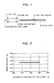
- Fig. 1 is a drawing showing the configuration of a semiconductor laser module according to a first embodiment of the present invention.
- Fig. 2 is a graph showing the oscillation center wavelength range of the semiconductor laser element 1 capable of being pulled in by the fiber gratings 5 and 6 of the semiconductor laser module of Fig. 1.
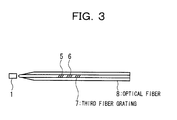
- Fig. 3 is a drawing showing the configuration of a semiconductor laser module according to a second embodiment of the present invention.
- Fig. 1 shows the configuration of a semiconductor laser module according to a first embodiment of the present invention, which has, as shown in Fig. 1, a semiconductor laser element 1, a first lens 2, a second lens 3, and an optical fiber 4.
- the semiconductor laser module of the first embodiment of the present invention has a high-efficiency optical coupling between the semiconductor laser element 1 and the optical fiber 4, wherein the laser light emitted from the semiconductor laser element 1 is extracted via the optical fiber 4.
- a first fiber grating 5 and a second fiber grating 6 having substantially same reflection center wavelength, respectively, are provided in the optical fiber 4.
- the first lens 2 is a lens that converts the emitted light from the semiconductor laser element 1 to the parallel light.
- the second lens 3 is a lens that focuses the parallel light from the first lens 1 onto the end face of the optical fiber 4, so that it incident thereto with good efficiency.
- the end face of the optical fiber 4 is polished at an inclination, so that light reflected from the end face does not return to the semiconductor laser element 1. That is, the shape of the end face of the optical fiber 4 is processed so that the light is reflected outside the region of incidence to the second lens 3.
- the end face of the optical fiber 4 is further coated with a anti-reflective film.
- the optical fiber 4 has formed in it a first fiber grating 5 and a second fiber grating 6.
- Each of the first and second fiber gratings 5 and 6 is formed, for example, by exposing the core part of the optical fiber 4 to ultraviolet light so as to cause a periodic variation in the index of refraction, thereby forming a diffraction grating.
- Each of the reflection center wavelengths and half band width of the first fiber grating 5 and the second fiber grating 6 can be respectively set to the single arbitrary wavelength and half band width to which stabilization is to be achieved within the oscillation range of the semiconductor laser element 1.
- the reflection center wavelength of the first fiber grating 5 and the second fiber grating 6 are set to 975 nm
- the half band width of the first fiber grating 5 and the second fiber grating 6 are made to be in the range from 0.5 to 3.0 nm.
- the reflection center wavelengths of the first fiber grating 5 and the second fiber grating 6 are set to 975 nm, there is not necessarily any need to set the reflection center wavelength of the first and second fiber gratings to one and the same wavelength. That is, it is sufficient that the reflection center wavelengths of the first fiber grating 5 and the second fiber grating 6 be set to substantially one and the same wavelength.
- the wavelength difference between the reflection center wavelength of the first fiber grating 5 and the reflection center wavelength of the second fiber grating 6 is set to a value no greater than 1.0 nm. That is, the statement that the reflection center wavelength of the first fiber grating 5 and the reflection center wavelength of the second fiber grating 6 are substantially one and the same means that the wavelength difference between these reflection center wavelengths is 1.0 nm or less.
- the reflectivities of the first fiber grating 5 and the second fiber grating 6 be set to approximately 0.5% to 8%. In this case, the reflectivities of the first and second fiber gratings 5 and 6 are each set to 3%.
- the distance between the first fiber grating 5 and the semiconductor laser element 1 (strictly speaking, the rear surface of the semiconductor laser element 1) to at least 10 cm.
- the distance between the first fiber grating 5 and the second fiber grating 6 can be arbitrarily set, it is desirable the distance be no greater than 50 cm, considering the housing of the fiber gratings within the module itself.
- the spectrum of the broadened laser light emitted from the semiconductor laser element 1 has relatively wide-band wavelength components.
- This laser light is converted to parallel light by the first lens 2, and then is collected by the second lens 3.
- the collected laser light is then focused onto the end face of the optical fiber 4, and is propagated through the optical fiber 4.
- Part of the laser light propagated through the optical fiber 4 is reflected by the first fiber grating 5 and the second fiber grating 6.
- the reflected laser light proceeds in the reverse direction and, after propagating through the optical fiber 4, passes through the second lens 3 and then the first lens 2, after which it returns to the semiconductor laser element 1.
- An external resonator is formed by the rear surface (Hr surface) of the semiconductor laser element 1 and the fiber gratings 5 and 6, enabling laser oscillation in a wavelength band established by the diffraction gratings of the fiber gratings 5 and 6, which have substantially one and the same reflection center wavelength. The result of this is that laser light with a stabilized wavelength is emitted from a semiconductor laser module according to the first embodiment.
- a semiconductor laser module In a semiconductor laser module according to the first embodiment of the present invention, because two laser lights from the first fiber grating 5 and the second fiber grating 6 return to the semiconductor laser element 1, that is, because there are a plurality of reflection points as seen from the semiconductor laser element 1, it is possible to effectively reduce the coherency of the laser light. By doing this, it is possible to eliminate a kink in the light output characteristics, such as the light output versus drive current characteristics.
- Fig. 2 shows the range of reflection center wavelength of a semiconductor laser element 1 that can be pulled in to the fiber gratings 5 and 6 of the semiconductor laser module.
- the horizontal axis represents the oscillation center wavelength of the semiconductor laser element 1
- FIG. 3 shows a semiconductor laser module according to the second embodiment, in which the same elements as in the first embodiment are assigned the same reference numerals.
- the semiconductor laser module shown in Fig. 3 has a semiconductor laser element 1 and an optical fiber 8.
- the semiconductor laser module according to the second embodiment of the present invention differs from that of the first embodiment in that, without using a lens in the optics system thereof, it uses a wedge-shaped fiber, formed by processing the end face of the optical fiber 8.
- An additional distinction from the semiconductor laser module of the first embodiment is that, in the semiconductor laser module according to the second embodiment, in addition to the first fiber grating 5 and the second fiber grating 6, a third fiber grating 7 is provided in the optical fiber 8.
- the reflection center wavelength of the third fiber grating 7 in this case is set so as to be substantially the same as the reflection center wavelength of the first fiber grating 5 and the second fiber grating 6. That is, the wavelength difference between the reflection center wavelength of the third fiber grating 7 and the reflection center wavelength of the first fiber grating 5 is 1.0 nm or less, the wavelength difference between the reflection center wavelength of the third fiber grating 7 and the second fiber grating 6 is 1.0 nm or less, and the wavelength difference between the first fiber grating 5 and the reflection center wavelength of the second fiber grating 6 is 1.0 nm or less.
- the semiconductor laser module according to the second embodiment of the present invention similar to the semiconductor laser module of the first embodiment, it is clear that not only is the wavelength of the laser light emitted from the module itself stabilized over a wide range of oscillation center wavelength of the semiconductor laser element 1, but also any kink in the light output characteristics is eliminated.
- a first effect achieved by the present module as described in detail above is the prevention of variation in the wavelength of the laser light emitted from the module even if there is a large variation in the oscillation center wavelength of the semiconductor laser element, and avoidance of a kink occurring in the light output characteristics.
- the reason for this is that, by forming in an optical fiber a plurality of fiber gratings having substantially one and the same reflection center wavelength, it is possible to pull the laser light from the semiconductor laser element into the fiber gratings over a broad range of oscillation center wavelength of the semiconductor laser element. Additionally, because there are a plurality of reflection points as seen from the semiconductor laser element, it is possible to effectively reduce the coherency of the laser light as seen from the semiconductor laser element.
- a second effect achieved by the present module is the provision of a low-cost semiconductor laser module.
- the reason for this is that, because it is possible to extract laser light with a stabilized wavelength even if there is a large variation in the oscillation center wavelength of the semiconductor laser element, the range of semiconductor laser element usable in the semiconductor laser module is broadened, thereby eliminating the need to select semiconductor laser elements for use in the semiconductor laser module.
Landscapes
- Physics & Mathematics (AREA)
- Condensed Matter Physics & Semiconductors (AREA)
- General Physics & Mathematics (AREA)
- Electromagnetism (AREA)
- Optics & Photonics (AREA)
- Optical Couplings Of Light Guides (AREA)
- Semiconductor Lasers (AREA)
Abstract
Description
- The present invention relates to a semiconductor laser module, and more particularly to a semiconductor laser module having an external resonator.
- In a semiconductor laser module of the past, the most general technology for stabilizing the wavelength of the laser light output from the module was that of forming in an optical fiber one fiber grating having a diffraction grating at a wavelength at which the semiconductor laser can oscillate, and to form an external resonator by the rear surface (Hr surface) of the semiconductor laser element and the fiber grating formed on the optical fiber.
- For example, in Journal of Lightwave Technology, Vol. 15, No. 8, August 1997, there is a description of technology in which an external resonator is formed by a 980 nm band laser element and a fiber grating formed in an optical fiber (the center reflected wavelength of which is 975 nm having a reflectivity of 2 to 4%), thereby stabilizing the wavelength of the laser light emitted from the semiconductor laser module to 975 nm.
- The above-noted technology, intended for the purpose of stabilizing the wavelength of the laser light output from a semiconductor laser module, has the following problem.
- Specifically, because there is a limit to the center oscillation wavelength of the semiconductor laser element which can be pulled in by a fiber grating, the farther mutually removed are the center reflection wavelength of the fiber grating and the center oscillation wavelength of the semiconductor laser element, the more difficult it is to pull in the laser light emitted from the semiconductor laser element to the wavelength of the fiber grating. In this case, therefore, there is the problem of additional oscillation at the stand-alone oscillation wavelength of the semiconductor laser element in addition to the oscillation at the wavelength established by the fiber grating, thereby causing the light output to have an unstable wavelength.
- With further distance between the fiber grating reflection center wavelength and the center oscillation wavelength of the semiconductor laser element, it becomes absolutely impossible to pull in the laser light from the semiconductor laser element to the wavelength established by the fiber grating, resulting in the semiconductor laser element oscillating at its own center oscillation wavelength, with light being output from the semiconductor laser module at this stand-alone semiconductor laser element oscillation wavelength.
- Technology intended for solving the above-noted problem is proposed in the Japanese Unexamined Patent Publication (KOKAI) No.2000-131559 (hereinafter referred to as the first disclosure), which shows a laser diode module. The laser diode module of the first disclosure is one in which a laser diode light source with an internal laser diode chip is optically coupled to an optical fiber. The optical fiber is a grating fiber, the reflection center wavelength of which is established so as to be 2 to 10 nm shorter than the oscillation center wavelength of the laser diode chip at 25°C.
- More specifically, in the laser diode module of the first disclosure, a chip having oscillation center wavelengths of 968 nm at 0°C, 975 nm at 25°C and 981 nm at 40°C is used as the laser diode chip, and the center reflection center wavelength of the optical fiber grating is set to be 970 nm. In a laser diode module having this configuration, according to the first disclosure, over a temperature variation of ±25°C with respect to the normal ambient temperature of 25°C, it is possible to lock the laser diode oscillation center wavelength to the fiber grating reflection center wavelength of 970 nm.
- With the above-noted technology of the first disclosure, however, when fabricating a semiconductor laser module because it is necessary to achieve somewhat of a coincidence between the semiconductor laser element oscillation center wavelength and the reflection center wavelength of the fiber grating, it is necessary to select the semiconductor laser element to be used, this being disadvantageous from the standpoint of fabricating a low-cost semiconductor laser module.
- Given the above, in order to stabilize the wavelength of the laser light from a semiconductor laser module, and also solve the above-noted problem with the technology of the first disclosure, the oscillation center wavelength range of the semiconductor laser module that can be pulled into the wavelength of the fiber grating can be broadened. The oscillator center wavelength of a semiconductor laser element that can be pulled into the wavelength of a fiber grating is generally established by the relationship between the front-surface reflectivity of the semiconductor laser element and the fiber grating reflectivity, and it is most effective to make the fiber grating reflectivity high.
- However, if the reflectivity of the fiber grating is merely made high, the coherency of the reflected light from the fiber grating as seen from the semiconductor laser element becomes high. Using this approach, therefore, although it is possible to broaden the range of semiconductor laser element oscillation center wavelength that can be pulled in to the wavelength of a fiber grating, problems arise such as a kink occurring in the light output characteristics after the module is fabricated.
- Technology intended to stabilize the light output characteristics is also proposed in the Japanese Unexamined Patent Publication (KOKAI) No.H10-293234 (referred to hereinafter as the second disclosure). In a semiconductor laser module described in the second disclosure, fiber gratings which reflect light of mutually different wavelengths is formed in an optical fiber. These two fiber gratings are formed within the package that holds the semiconductor laser chip, or in a location at which a coupling means that couples the package to an optical fiber is disposed.
- Although with a semiconductor laser module as described in the second disclosure, it is possible to stabilize the light output characteristics, because the reflection center wavelengths of the two fiber gratings forming in the optical fiber mutually differ, there is the problem of oscillation in two modes having different wavelengths.
- In the Japanese Unexamined Patent Publication (KOKAI) No. 2000-194023 (hereinafter referred to as the third disclosure), there is a description of a semiconductor laser module in which two fiber gratings having mutually different reflection wavelengths, wherein the reflection center wavelengths of these two fiber gratings are set as to be above and below a prescribed wavelength of the light emitted from a semiconductor laser element.
- Because the semiconductor laser module of the third disclosure is configured as noted above, in the case in which the oscillation center wavelength of the semiconductor laser module is shorter than the reflection center wavelengths of the two fiber gratings, oscillation occurs at only the wavelength established by the fiber grating having the shorter reflection center wavelength. Further in the case in which the oscillation center wavelength of the semiconductor laser module is between two reflection center wavelengths of the two fiber gratings, oscillations occur at the two wavelength established by the two fiber gratings.Similarly, in the case in which the oscillation center wavelength of the semiconductor laser module is longer than the reflection center wavelengths of the two fiber gratings, oscillation occurs at only the wavelength established by the fiber grating having the longer reflection center wavelength. Thus, with a semiconductor laser module according to the third disclosure, there is the problem that the wavelength of the laser light obtained from the optical fiber will differ, depending upon the oscillation center wavelength of the semiconductor laser module.
- Specifically, a first aspect of the present invention is a semiconductor laser module comprising: a semiconductor laser element; an optical fiber optically coupled to the semiconductor laser element; and a plurality of fiber gratings provided in the optical fiber; wherein a center wavelength of a reflecting light of the fiber gratings is established to be substantially equal each other.
- The second aspect of the present invention is a semiconductor laser module comprising: a semiconductor laser element; an optical fiber optically coupled to the semiconductor laser element; and a plurality of fiber gratings provided in the optical fiber; wherein a center wavelength of a reflecting light of the fiber gratings is established to be equal each other.
- In the third aspect of the present invention, a wavelength difference among said center wavelengths of said plurality of fiber gratings is 1.0 nm or less.
- In the fourth aspect of the present invention, a distance between one of the fiber gratings and the semiconductor laser element is 50 cm or greater.
- The above-described laser module operates in 'the following manner. A plurality of fiber gratings having substantially the same different reflection center wavelengths are formed in an optical fiber, this plurality of fiber gratings reflecting to the semiconductor laser module only components of the reflection center wavelength of the laser light emitted from the semiconductor laser element. In this manner, by using a plurality of fiber gratings having substantially one and the same reflection center wavelength, even if the wavelength of the laser light emitted from the semiconductor laser element changes greatly, because it is possible to pull the laser light into the plurality of fiber gratings, it is possible to stabilize the wavelength of the laser light emitted from the semiconductor laser element to the reflection center wavelength. Additionally, in contrast to the case in which the reflectivity of the fiber grating is merely made high, it is possible to prevent an increase in the coherency of the reflected light as seen from the semiconductor laser element, thereby enabling the achievement of output characteristics without a kink.
- Fig. 1 is a drawing showing the configuration of a semiconductor laser module according to a first embodiment of the present invention.
- Fig. 2 is a graph showing the oscillation center wavelength range of the
semiconductor laser element 1 capable of being pulled in by thefiber gratings - Fig. 3 is a drawing showing the configuration of a semiconductor laser module according to a second embodiment of the present invention.
- Embodiments of the present invention are described in detail below, with reference made to relevant accompanying drawings.
- Fig. 1 shows the configuration of a semiconductor laser module according to a first embodiment of the present invention, which has, as shown in Fig. 1, a
semiconductor laser element 1, afirst lens 2, asecond lens 3, and anoptical fiber 4. - The semiconductor laser module of the first embodiment of the present invention has a high-efficiency optical coupling between the
semiconductor laser element 1 and theoptical fiber 4, wherein the laser light emitted from thesemiconductor laser element 1 is extracted via theoptical fiber 4. - In the semiconductor laser module of the first embodiment, even if there is a large change in the oscillation center wavelength of the
semiconductor laser element 1 due to a change in temperature or the like, in order that there is no change in the wavelength of the laser light output from the module itself, afirst fiber grating 5 and asecond fiber grating 6 having substantially same reflection center wavelength, respectively, are provided in theoptical fiber 4. - The
first lens 2 is a lens that converts the emitted light from thesemiconductor laser element 1 to the parallel light. Thesecond lens 3 is a lens that focuses the parallel light from thefirst lens 1 onto the end face of theoptical fiber 4, so that it incident thereto with good efficiency. The end face of theoptical fiber 4 is polished at an inclination, so that light reflected from the end face does not return to thesemiconductor laser element 1. That is, the shape of the end face of theoptical fiber 4 is processed so that the light is reflected outside the region of incidence to thesecond lens 3. The end face of theoptical fiber 4 is further coated with a anti-reflective film. - The
optical fiber 4 has formed in it a first fiber grating 5 and a second fiber grating 6. Each of the first andsecond fiber gratings optical fiber 4 to ultraviolet light so as to cause a periodic variation in the index of refraction, thereby forming a diffraction grating. - Each of the reflection center wavelengths and half band width of the first fiber grating 5 and the
second fiber grating 6 can be respectively set to the single arbitrary wavelength and half band width to which stabilization is to be achieved within the oscillation range of thesemiconductor laser element 1. In this case, the reflection center wavelength of the first fiber grating 5 and thesecond fiber grating 6 are set to 975 nm, and the half band width of the first fiber grating 5 and thesecond fiber grating 6 are made to be in the range from 0.5 to 3.0 nm. - Although in the above-noted description the reflection center wavelengths of the first fiber grating 5 and the
second fiber grating 6 are set to 975 nm, there is not necessarily any need to set the reflection center wavelength of the first and second fiber gratings to one and the same wavelength. That is, it is sufficient that the reflection center wavelengths of the first fiber grating 5 and thesecond fiber grating 6 be set to substantially one and the same wavelength. - In this case, if there is too much separation between the reflection center wavelength of the
first fiber grating 5 and the reflection center wavelength of thesecond fiber grating 6, problems can occur of a widening of the half band width of the wavelength extracted from the semiconductor laser module, or of oscillation at each of the wavelengths established respectively by thefirst fiber grating 5 and thesecond fiber grating 6. - To prevent the occurrence of these problems, the wavelength difference between the reflection center wavelength of the
first fiber grating 5 and the reflection center wavelength of thesecond fiber grating 6 is set to a value no greater than 1.0 nm. That is, the statement that the reflection center wavelength of the first fiber grating 5 and the reflection center wavelength of thesecond fiber grating 6 are substantially one and the same means that the wavelength difference between these reflection center wavelengths is 1.0 nm or less. - In order to prevent a high coherency in the light reflected from the
first fiber grating 5 and the second fiber grating 6 as seen from thesemiconductor laser element 1, it is desirable that the reflectivities of thefirst fiber grating 5 and thesecond fiber grating 6 be set to approximately 0.5% to 8%. In this case, the reflectivities of the first andsecond fiber gratings - It is sufficient to set the distance between the
first fiber grating 5 and the semiconductor laser element 1 (strictly speaking, the rear surface of the semiconductor laser element 1) to at least 10 cm. However, in order to lower the coherency of the reflected light from the first andsecond fiber gratings semiconductor laser element 1, it is desirable to use the weakening of interference of the laser light as it propagates through an optical fiber, and to set the distance betweenfirst fiber grating 5 and the semiconductor laser element 1 (strictly speaking, the rear surface of the semiconductor laser element 1) to at least 50 cm. - Although the distance between the first fiber grating 5 and the
second fiber grating 6 can be arbitrarily set, it is desirable the distance be no greater than 50 cm, considering the housing of the fiber gratings within the module itself. - The operation of a semiconductor laser module according to the first embodiment is described below, with reference to relevant drawings.
- In Fig. 1, the spectrum of the broadened laser light emitted from the
semiconductor laser element 1 has relatively wide-band wavelength components. This laser light is converted to parallel light by thefirst lens 2, and then is collected by thesecond lens 3. The collected laser light is then focused onto the end face of theoptical fiber 4, and is propagated through theoptical fiber 4. - Part of the laser light propagated through the
optical fiber 4 is reflected by the first fiber grating 5 and the second fiber grating 6. The reflected laser light proceeds in the reverse direction and, after propagating through theoptical fiber 4, passes through thesecond lens 3 and then thefirst lens 2, after which it returns to thesemiconductor laser element 1. An external resonator is formed by the rear surface (Hr surface) of thesemiconductor laser element 1 and thefiber gratings fiber gratings - In a semiconductor laser module according to the first embodiment of the present invention, because two laser lights from the first fiber grating 5 and the second fiber grating 6 return to the
semiconductor laser element 1, that is, because there are a plurality of reflection points as seen from thesemiconductor laser element 1, it is possible to effectively reduce the coherency of the laser light. By doing this, it is possible to eliminate a kink in the light output characteristics, such as the light output versus drive current characteristics. - Fig. 2 shows the range of reflection center wavelength of a
semiconductor laser element 1 that can be pulled in to thefiber gratings semiconductor laser element 1, and the vertical axis represents the wavelength of the laser light after fabricating into a module. It can be seen from Fig. 2 that using a semiconductor laser module according to the first embodiment of the present invention, over a range of oscillation center wavelength Δλ=23 nm of the semiconductor laser element 1 (oscillation center wavelength: 967 to 990 nm), the wavelength of the laser light emitted from the module itself is stabilized to 975 nm. - Although in the semiconductor laser module according to the first embodiment two fiber gratings are used, It will be understood that this is not a restriction, and that three or more fiber gratings can be formed in the
optical fiber 4. - A second embodiment of the present invention is described below, with reference to Fig. 3, which shows a semiconductor laser module according to the second embodiment, in which the same elements as in the first embodiment are assigned the same reference numerals. The semiconductor laser module shown in Fig. 3 has a
semiconductor laser element 1 and anoptical fiber 8. - That is, the semiconductor laser module according to the second embodiment of the present invention differs from that of the first embodiment in that, without using a lens in the optics system thereof, it uses a wedge-shaped fiber, formed by processing the end face of the
optical fiber 8. An additional distinction from the semiconductor laser module of the first embodiment is that, in the semiconductor laser module according to the second embodiment, in addition to the first fiber grating 5 and the second fiber grating 6, a third fiber grating 7 is provided in theoptical fiber 8. - The reflection center wavelength of the third fiber grating 7 in this case is set so as to be substantially the same as the reflection center wavelength of the first fiber grating 5 and the second fiber grating 6. That is, the wavelength difference between the reflection center wavelength of the third fiber grating 7 and the reflection center wavelength of the first fiber grating 5 is 1.0 nm or less, the wavelength difference between the reflection center wavelength of the third fiber grating 7 and the second fiber grating 6 is 1.0 nm or less, and the wavelength difference between the first fiber grating 5 and the reflection center wavelength of the second fiber grating 6 is 1.0 nm or less.
- In the semiconductor laser module according to the second embodiment of the present invention, similar to the semiconductor laser module of the first embodiment, it is clear that not only is the wavelength of the laser light emitted from the module itself stabilized over a wide range of oscillation center wavelength of the
semiconductor laser element 1, but also any kink in the light output characteristics is eliminated. - A first effect achieved by the present module as described in detail above is the prevention of variation in the wavelength of the laser light emitted from the module even if there is a large variation in the oscillation center wavelength of the semiconductor laser element, and avoidance of a kink occurring in the light output characteristics. The reason for this is that, by forming in an optical fiber a plurality of fiber gratings having substantially one and the same reflection center wavelength, it is possible to pull the laser light from the semiconductor laser element into the fiber gratings over a broad range of oscillation center wavelength of the semiconductor laser element. Additionally, because there are a plurality of reflection points as seen from the semiconductor laser element, it is possible to effectively reduce the coherency of the laser light as seen from the semiconductor laser element.
- A second effect achieved by the present module is the provision of a low-cost semiconductor laser module. The reason for this is that, because it is possible to extract laser light with a stabilized wavelength even if there is a large variation in the oscillation center wavelength of the semiconductor laser element, the range of semiconductor laser element usable in the semiconductor laser module is broadened, thereby eliminating the need to select semiconductor laser elements for use in the semiconductor laser module.
Claims (4)
- A semiconductor laser module comprising:wherein the center wavelengths of reflected light from said fiber gratings are established to be substantially equal to each other.a semiconductor laser element (1);an optical fiber optically (4) coupled to said semiconductor laser element; anda plurality of fiber gratings (5,6) provided in said optical fiber;
- A semiconductor laser module according to claim 1,
wherein the center wavelengths of reflected light from said fiber gratings are established to be equal to each other. - A semiconductor laser module according to claim 1,
wherein the wavelength difference among said center wavelengths of said plurality of fiber gratings is 1.0 nm or less. - A semiconductor laser module according to claim 1, 2 or 3, wherein the distance between one of said fiber gratings and said semiconductor laser element is 50 cm or greater.
Priority Applications (3)
| Application Number | Priority Date | Filing Date | Title |
|---|---|---|---|
| JP2001145738A JP2002341195A (en) | 2001-05-16 | 2001-05-16 | Semiconductor laser module |
| US10/143,754 US6965627B2 (en) | 2001-05-16 | 2002-05-14 | Semiconductor laser module |
| EP02010993A EP1363147A3 (en) | 2001-05-16 | 2002-05-17 | Semiconductor laser module |
Applications Claiming Priority (2)
| Application Number | Priority Date | Filing Date | Title |
|---|---|---|---|
| JP2001145738A JP2002341195A (en) | 2001-05-16 | 2001-05-16 | Semiconductor laser module |
| EP02010993A EP1363147A3 (en) | 2001-05-16 | 2002-05-17 | Semiconductor laser module |
Publications (2)
| Publication Number | Publication Date |
|---|---|
| EP1363147A2 true EP1363147A2 (en) | 2003-11-19 |
| EP1363147A3 EP1363147A3 (en) | 2004-02-18 |
Family
ID=31189517
Family Applications (1)
| Application Number | Title | Priority Date | Filing Date |
|---|---|---|---|
| EP02010993A Withdrawn EP1363147A3 (en) | 2001-05-16 | 2002-05-17 | Semiconductor laser module |
Country Status (3)
| Country | Link |
|---|---|
| US (1) | US6965627B2 (en) |
| EP (1) | EP1363147A3 (en) |
| JP (1) | JP2002341195A (en) |
Families Citing this family (3)
| Publication number | Priority date | Publication date | Assignee | Title |
|---|---|---|---|---|
| WO2006059389A1 (en) * | 2004-12-03 | 2006-06-08 | Mitsubishi Denki Kabushiki Kaisha | Light wavelength conversion light source |
| KR20140092214A (en) * | 2013-01-15 | 2014-07-23 | 오므론 가부시키가이샤 | Laser oscillator |
| CN110380326B (en) * | 2019-07-29 | 2020-10-23 | 武汉电信器件有限公司 | Optical signal output device and method, and storage medium |
Citations (1)
| Publication number | Priority date | Publication date | Assignee | Title |
|---|---|---|---|---|
| EP1087479A1 (en) * | 1999-09-21 | 2001-03-28 | JDS Uniphase Corporation | Stabilized laser source |
Family Cites Families (16)
| Publication number | Priority date | Publication date | Assignee | Title |
|---|---|---|---|---|
| JPS6132488A (en) | 1984-07-23 | 1986-02-15 | Nippon Telegr & Teleph Corp <Ntt> | Semiconductor laser device |
| US5305335A (en) * | 1989-12-26 | 1994-04-19 | United Technologies Corporation | Single longitudinal mode pumped optical waveguide laser arrangement |
| US5166940A (en) * | 1991-06-04 | 1992-11-24 | The Charles Stark Draper Laboratory, Inc. | Fiber laser and method of making same |
| US5485481A (en) | 1994-06-28 | 1996-01-16 | Seastar Optics Inc. | Fibre-grating-stabilized diode laser |
| JP3534550B2 (en) * | 1995-11-01 | 2004-06-07 | 住友電気工業株式会社 | OTDR device |
| JP3206536B2 (en) | 1997-02-21 | 2001-09-10 | 住友電気工業株式会社 | Semiconductor laser module |
| JP3710077B2 (en) | 1997-11-28 | 2005-10-26 | 住友電気工業株式会社 | External cavity semiconductor laser |
| US7605149B1 (en) | 1998-07-13 | 2009-10-20 | University Of South Florida | Modulation of the phospholipase A2 pathway as a therapeutic |
| JP2000082864A (en) | 1998-09-04 | 2000-03-21 | Nippon Telegr & Teleph Corp <Ntt> | Laser device |
| JP2000131559A (en) | 1998-10-28 | 2000-05-12 | Mitsubishi Chemicals Corp | LD module and method of using the same |
| JP2000174381A (en) | 1998-12-04 | 2000-06-23 | Nec Corp | Semiconductor laser module |
| JP2000194023A (en) | 1998-12-28 | 2000-07-14 | Nec Corp | Semiconductor laser module |
| EP1067644B1 (en) | 1999-01-27 | 2014-07-30 | Furukawa Electric Co., Ltd. | Semiconductor laser module |
| JP3833882B2 (en) | 1999-09-24 | 2006-10-18 | 古河電気工業株式会社 | Semiconductor laser module |
| US6407855B1 (en) * | 1999-10-29 | 2002-06-18 | Sdl, Inc. | Multiple wavelength optical sources |
| JP3412584B2 (en) | 1999-11-12 | 2003-06-03 | 住友電気工業株式会社 | External cavity type semiconductor laser |
-
2001
- 2001-05-16 JP JP2001145738A patent/JP2002341195A/en active Pending
-
2002
- 2002-05-14 US US10/143,754 patent/US6965627B2/en not_active Expired - Fee Related
- 2002-05-17 EP EP02010993A patent/EP1363147A3/en not_active Withdrawn
Patent Citations (1)
| Publication number | Priority date | Publication date | Assignee | Title |
|---|---|---|---|---|
| EP1087479A1 (en) * | 1999-09-21 | 2001-03-28 | JDS Uniphase Corporation | Stabilized laser source |
Also Published As
| Publication number | Publication date |
|---|---|
| JP2002341195A (en) | 2002-11-27 |
| EP1363147A3 (en) | 2004-02-18 |
| US6965627B2 (en) | 2005-11-15 |
| US20020172252A1 (en) | 2002-11-21 |
Similar Documents
| Publication | Publication Date | Title |
|---|---|---|
| US6044093A (en) | Fibre-grating-stabilized diode laser | |
| US6411639B1 (en) | Semiconductor laser module with an external resonator including a band-pass filter and reflective element | |
| US20120163821A1 (en) | Multi-wavelength optical source generator | |
| US4427261A (en) | Optical transmission system having reduced modal noise | |
| US6700904B2 (en) | Light source for an external cavity laser | |
| US6707838B2 (en) | Stray light cutting structure for optical device | |
| US7317739B2 (en) | Mode-locked laser using a mode-locking wavelength selective reflector | |
| KR20050084018A (en) | Optical via for three dimensional interconnection | |
| US6965627B2 (en) | Semiconductor laser module | |
| US5768304A (en) | Laser | |
| US7046880B2 (en) | Optical coupling element and optical device | |
| KR100550141B1 (en) | Tunable External Resonant Laser Diode Using Variable Optical Deflector | |
| JP2004511914A (en) | Tunable single mode laser device | |
| US20230296841A1 (en) | Optical component | |
| US6556597B2 (en) | Laser diode module | |
| US7751461B2 (en) | Linewidth-narrowed excimer laser cavity | |
| US6665323B2 (en) | Semiconductor laser module constituted by optically coupling optical fiber having fiber grating and laser diode | |
| JP2003229630A (en) | Laser diode module | |
| JP2006073549A (en) | External resonator-type wavelength variable optical source | |
| JPH1117286A (en) | Tunable laser device | |
| JPH03116992A (en) | Semiconductor laser device | |
| JPH1168233A (en) | Variable wavelength laser light source | |
| US20240405516A1 (en) | Semiconductor optical amplification element | |
| JP2000174381A (en) | Semiconductor laser module | |
| WO2006104034A1 (en) | External resonance type semiconductor laser |
Legal Events
| Date | Code | Title | Description |
|---|---|---|---|
| PUAI | Public reference made under article 153(3) epc to a published international application that has entered the european phase |
Free format text: ORIGINAL CODE: 0009012 |
|
| AK | Designated contracting states |
Kind code of ref document: A2 Designated state(s): AT BE CH CY DE DK ES FI FR GB GR IE IT LI LU MC NL PT SE TR |
|
| AX | Request for extension of the european patent |
Extension state: AL LT LV MK RO SI |
|
| PUAL | Search report despatched |
Free format text: ORIGINAL CODE: 0009013 |
|
| AK | Designated contracting states |
Kind code of ref document: A3 Designated state(s): AT BE CH CY DE DK ES FI FR GB GR IE IT LI LU MC NL PT SE TR |
|
| AX | Request for extension of the european patent |
Extension state: AL LT LV MK RO SI |
|
| 17P | Request for examination filed |
Effective date: 20040216 |
|
| 17Q | First examination report despatched |
Effective date: 20040406 |
|
| AKX | Designation fees paid |
Designated state(s): FR GB |
|
| REG | Reference to a national code |
Ref country code: DE Ref legal event code: 8566 |
|
| STAA | Information on the status of an ep patent application or granted ep patent |
Free format text: STATUS: THE APPLICATION HAS BEEN WITHDRAWN |
|
| 18W | Application withdrawn |
Effective date: 20101123 |