EP1363094A1 - System and method for introducing low pressure reflux to a high pressure column without a pump - Google Patents
System and method for introducing low pressure reflux to a high pressure column without a pump Download PDFInfo
- Publication number
- EP1363094A1 EP1363094A1 EP03252651A EP03252651A EP1363094A1 EP 1363094 A1 EP1363094 A1 EP 1363094A1 EP 03252651 A EP03252651 A EP 03252651A EP 03252651 A EP03252651 A EP 03252651A EP 1363094 A1 EP1363094 A1 EP 1363094A1
- Authority
- EP
- European Patent Office
- Prior art keywords
- high pressure
- stream
- nitrogen
- reflux
- pressure column
- Prior art date
- Legal status (The legal status is an assumption and is not a legal conclusion. Google has not performed a legal analysis and makes no representation as to the accuracy of the status listed.)
- Withdrawn
Links
Images





Classifications
-
- F—MECHANICAL ENGINEERING; LIGHTING; HEATING; WEAPONS; BLASTING
- F25—REFRIGERATION OR COOLING; COMBINED HEATING AND REFRIGERATION SYSTEMS; HEAT PUMP SYSTEMS; MANUFACTURE OR STORAGE OF ICE; LIQUEFACTION SOLIDIFICATION OF GASES
- F25J—LIQUEFACTION, SOLIDIFICATION OR SEPARATION OF GASES OR GASEOUS OR LIQUEFIED GASEOUS MIXTURES BY PRESSURE AND COLD TREATMENT OR BY BRINGING THEM INTO THE SUPERCRITICAL STATE
- F25J3/00—Processes or apparatus for separating the constituents of gaseous or liquefied gaseous mixtures involving the use of liquefaction or solidification
- F25J3/02—Processes or apparatus for separating the constituents of gaseous or liquefied gaseous mixtures involving the use of liquefaction or solidification by rectification, i.e. by continuous interchange of heat and material between a vapour stream and a liquid stream
- F25J3/04—Processes or apparatus for separating the constituents of gaseous or liquefied gaseous mixtures involving the use of liquefaction or solidification by rectification, i.e. by continuous interchange of heat and material between a vapour stream and a liquid stream for air
- F25J3/04248—Generation of cold for compensating heat leaks or liquid production, e.g. by Joule-Thompson expansion
- F25J3/04284—Generation of cold for compensating heat leaks or liquid production, e.g. by Joule-Thompson expansion using internal refrigeration by open-loop gas work expansion, e.g. of intermediate or oxygen enriched (waste-)streams
- F25J3/04309—Generation of cold for compensating heat leaks or liquid production, e.g. by Joule-Thompson expansion using internal refrigeration by open-loop gas work expansion, e.g. of intermediate or oxygen enriched (waste-)streams of nitrogen
-
- F—MECHANICAL ENGINEERING; LIGHTING; HEATING; WEAPONS; BLASTING
- F25—REFRIGERATION OR COOLING; COMBINED HEATING AND REFRIGERATION SYSTEMS; HEAT PUMP SYSTEMS; MANUFACTURE OR STORAGE OF ICE; LIQUEFACTION SOLIDIFICATION OF GASES
- F25J—LIQUEFACTION, SOLIDIFICATION OR SEPARATION OF GASES OR GASEOUS OR LIQUEFIED GASEOUS MIXTURES BY PRESSURE AND COLD TREATMENT OR BY BRINGING THEM INTO THE SUPERCRITICAL STATE
- F25J3/00—Processes or apparatus for separating the constituents of gaseous or liquefied gaseous mixtures involving the use of liquefaction or solidification
- F25J3/02—Processes or apparatus for separating the constituents of gaseous or liquefied gaseous mixtures involving the use of liquefaction or solidification by rectification, i.e. by continuous interchange of heat and material between a vapour stream and a liquid stream
- F25J3/04—Processes or apparatus for separating the constituents of gaseous or liquefied gaseous mixtures involving the use of liquefaction or solidification by rectification, i.e. by continuous interchange of heat and material between a vapour stream and a liquid stream for air
- F25J3/04406—Processes or apparatus for separating the constituents of gaseous or liquefied gaseous mixtures involving the use of liquefaction or solidification by rectification, i.e. by continuous interchange of heat and material between a vapour stream and a liquid stream for air using a dual pressure main column system
- F25J3/04412—Processes or apparatus for separating the constituents of gaseous or liquefied gaseous mixtures involving the use of liquefaction or solidification by rectification, i.e. by continuous interchange of heat and material between a vapour stream and a liquid stream for air using a dual pressure main column system in a classical double column flowsheet, i.e. with thermal coupling by a main reboiler-condenser in the bottom of low pressure respectively top of high pressure column
-
- F—MECHANICAL ENGINEERING; LIGHTING; HEATING; WEAPONS; BLASTING
- F25—REFRIGERATION OR COOLING; COMBINED HEATING AND REFRIGERATION SYSTEMS; HEAT PUMP SYSTEMS; MANUFACTURE OR STORAGE OF ICE; LIQUEFACTION SOLIDIFICATION OF GASES
- F25J—LIQUEFACTION, SOLIDIFICATION OR SEPARATION OF GASES OR GASEOUS OR LIQUEFIED GASEOUS MIXTURES BY PRESSURE AND COLD TREATMENT OR BY BRINGING THEM INTO THE SUPERCRITICAL STATE
- F25J3/00—Processes or apparatus for separating the constituents of gaseous or liquefied gaseous mixtures involving the use of liquefaction or solidification
- F25J3/02—Processes or apparatus for separating the constituents of gaseous or liquefied gaseous mixtures involving the use of liquefaction or solidification by rectification, i.e. by continuous interchange of heat and material between a vapour stream and a liquid stream
- F25J3/04—Processes or apparatus for separating the constituents of gaseous or liquefied gaseous mixtures involving the use of liquefaction or solidification by rectification, i.e. by continuous interchange of heat and material between a vapour stream and a liquid stream for air
- F25J3/04763—Start-up or control of the process; Details of the apparatus used
- F25J3/04769—Operation, control and regulation of the process; Instrumentation within the process
- F25J3/04781—Pressure changing devices, e.g. for compression, expansion, liquid pumping
-
- F—MECHANICAL ENGINEERING; LIGHTING; HEATING; WEAPONS; BLASTING
- F25—REFRIGERATION OR COOLING; COMBINED HEATING AND REFRIGERATION SYSTEMS; HEAT PUMP SYSTEMS; MANUFACTURE OR STORAGE OF ICE; LIQUEFACTION SOLIDIFICATION OF GASES
- F25J—LIQUEFACTION, SOLIDIFICATION OR SEPARATION OF GASES OR GASEOUS OR LIQUEFIED GASEOUS MIXTURES BY PRESSURE AND COLD TREATMENT OR BY BRINGING THEM INTO THE SUPERCRITICAL STATE
- F25J3/00—Processes or apparatus for separating the constituents of gaseous or liquefied gaseous mixtures involving the use of liquefaction or solidification
- F25J3/02—Processes or apparatus for separating the constituents of gaseous or liquefied gaseous mixtures involving the use of liquefaction or solidification by rectification, i.e. by continuous interchange of heat and material between a vapour stream and a liquid stream
- F25J3/04—Processes or apparatus for separating the constituents of gaseous or liquefied gaseous mixtures involving the use of liquefaction or solidification by rectification, i.e. by continuous interchange of heat and material between a vapour stream and a liquid stream for air
- F25J3/04763—Start-up or control of the process; Details of the apparatus used
- F25J3/04866—Construction and layout of air fractionation equipments, e.g. valves, machines
- F25J3/04872—Vertical layout of cold equipments within in the cold box, e.g. columns, heat exchangers etc.
- F25J3/04878—Side by side arrangement of multiple vessels in a main column system, wherein the vessels are normally mounted one upon the other or forming different sections of the same column
-
- F—MECHANICAL ENGINEERING; LIGHTING; HEATING; WEAPONS; BLASTING
- F25—REFRIGERATION OR COOLING; COMBINED HEATING AND REFRIGERATION SYSTEMS; HEAT PUMP SYSTEMS; MANUFACTURE OR STORAGE OF ICE; LIQUEFACTION SOLIDIFICATION OF GASES
- F25J—LIQUEFACTION, SOLIDIFICATION OR SEPARATION OF GASES OR GASEOUS OR LIQUEFIED GASEOUS MIXTURES BY PRESSURE AND COLD TREATMENT OR BY BRINGING THEM INTO THE SUPERCRITICAL STATE
- F25J2200/00—Processes or apparatus using separation by rectification
- F25J2200/50—Processes or apparatus using separation by rectification using multiple (re-)boiler-condensers at different heights of the column
- F25J2200/54—Processes or apparatus using separation by rectification using multiple (re-)boiler-condensers at different heights of the column in the low pressure column of a double pressure main column system
-
- F—MECHANICAL ENGINEERING; LIGHTING; HEATING; WEAPONS; BLASTING
- F25—REFRIGERATION OR COOLING; COMBINED HEATING AND REFRIGERATION SYSTEMS; HEAT PUMP SYSTEMS; MANUFACTURE OR STORAGE OF ICE; LIQUEFACTION SOLIDIFICATION OF GASES
- F25J—LIQUEFACTION, SOLIDIFICATION OR SEPARATION OF GASES OR GASEOUS OR LIQUEFIED GASEOUS MIXTURES BY PRESSURE AND COLD TREATMENT OR BY BRINGING THEM INTO THE SUPERCRITICAL STATE
- F25J2205/00—Processes or apparatus using other separation and/or other processing means
- F25J2205/02—Processes or apparatus using other separation and/or other processing means using simple phase separation in a vessel or drum
-
- F—MECHANICAL ENGINEERING; LIGHTING; HEATING; WEAPONS; BLASTING
- F25—REFRIGERATION OR COOLING; COMBINED HEATING AND REFRIGERATION SYSTEMS; HEAT PUMP SYSTEMS; MANUFACTURE OR STORAGE OF ICE; LIQUEFACTION SOLIDIFICATION OF GASES
- F25J—LIQUEFACTION, SOLIDIFICATION OR SEPARATION OF GASES OR GASEOUS OR LIQUEFIED GASEOUS MIXTURES BY PRESSURE AND COLD TREATMENT OR BY BRINGING THEM INTO THE SUPERCRITICAL STATE
- F25J2235/00—Processes or apparatus involving steps for increasing the pressure or for conveying of liquid process streams
- F25J2235/04—Processes or apparatus involving steps for increasing the pressure or for conveying of liquid process streams using a pressure accumulator
-
- F—MECHANICAL ENGINEERING; LIGHTING; HEATING; WEAPONS; BLASTING
- F25—REFRIGERATION OR COOLING; COMBINED HEATING AND REFRIGERATION SYSTEMS; HEAT PUMP SYSTEMS; MANUFACTURE OR STORAGE OF ICE; LIQUEFACTION SOLIDIFICATION OF GASES
- F25J—LIQUEFACTION, SOLIDIFICATION OR SEPARATION OF GASES OR GASEOUS OR LIQUEFIED GASEOUS MIXTURES BY PRESSURE AND COLD TREATMENT OR BY BRINGING THEM INTO THE SUPERCRITICAL STATE
- F25J2235/00—Processes or apparatus involving steps for increasing the pressure or for conveying of liquid process streams
- F25J2235/42—Processes or apparatus involving steps for increasing the pressure or for conveying of liquid process streams the fluid being nitrogen
-
- F—MECHANICAL ENGINEERING; LIGHTING; HEATING; WEAPONS; BLASTING
- F25—REFRIGERATION OR COOLING; COMBINED HEATING AND REFRIGERATION SYSTEMS; HEAT PUMP SYSTEMS; MANUFACTURE OR STORAGE OF ICE; LIQUEFACTION SOLIDIFICATION OF GASES
- F25J—LIQUEFACTION, SOLIDIFICATION OR SEPARATION OF GASES OR GASEOUS OR LIQUEFIED GASEOUS MIXTURES BY PRESSURE AND COLD TREATMENT OR BY BRINGING THEM INTO THE SUPERCRITICAL STATE
- F25J2245/00—Processes or apparatus involving steps for recycling of process streams
- F25J2245/42—Processes or apparatus involving steps for recycling of process streams the recycled stream being nitrogen
-
- F—MECHANICAL ENGINEERING; LIGHTING; HEATING; WEAPONS; BLASTING
- F25—REFRIGERATION OR COOLING; COMBINED HEATING AND REFRIGERATION SYSTEMS; HEAT PUMP SYSTEMS; MANUFACTURE OR STORAGE OF ICE; LIQUEFACTION SOLIDIFICATION OF GASES
- F25J—LIQUEFACTION, SOLIDIFICATION OR SEPARATION OF GASES OR GASEOUS OR LIQUEFIED GASEOUS MIXTURES BY PRESSURE AND COLD TREATMENT OR BY BRINGING THEM INTO THE SUPERCRITICAL STATE
- F25J2290/00—Other details not covered by groups F25J2200/00 - F25J2280/00
- F25J2290/62—Details of storing a fluid in a tank
Definitions
- This invention relates generally to air separation and more specifically to cryogenic air separation and nitrogen and/or oxygen production.
- a typical air separation unit for example the configuration shown in Figure 1, there are at least two distillation columns: a high pressure column 110, and a low pressure column 120. These columns are heat integrated through reboiler-condenser 130 and the low pressure column is usually built on top of the high pressure column.
- high pressure and low pressure columns can be built side-by-side.
- the reboiler-condenser can be located on top of the high pressure column (such as the configuration shown in Figure 2) or in the bottom of the low pressure column (shown in Figure 3). In both of these cases a pump is necessary.
- liquid oxygen in stream 240 is pumped, using pump 250, from the bottom of low pressure column 220 to reboiler 230 located on top of high pressure column 210.
- US-A-6,148,637 discloses a three component system, comprised of a lower pressure column, a higher pressure column, and a heat exchanger. Included in this system is a pump for transporting liquid from the bottom of the lower pressure column to a vaporizer-condenser at the top of the higher pressure column.
- nitrogen liquid in stream 360 is pumped, using pump 350, from reboiler-condenser 330 located in the bottom of low pressure column 320 back to the top of high pressure column 310 as reflux.
- pump 350 Usually two pumps instead of one are installed for the same service - a working pump and an idle nitrogen liquid pump that serves as a spare.
- Cryogenic liquid pumps are expensive, require periodic maintenance and, because they contain moving parts, are more likely to fail than stationary equipment.
- a column system for the production of nitrogen and/or oxygen with a dual reboiler and nitrogen expansion has been described in US-A-4,796,431, and is shown in Figure 4.
- air is introduced to high pressure column 410 and product nitrogen and oxygen are withdrawn from low pressure column 420.
- the columns are heat integrated by lower reboiler-condenser 430 and upper reboiler-condenser 440.
- Nitrogen in stream 432 from the top of high pressure column 410 is divided into streams 434 and 436.
- Stream 436 is expanded in expander 438, thus creating necessary refrigeration.
- the output of expander 438 is then condensed in upper reboiler-condenser 440 and the resulting stream 442 is divided into streams 444 and 446.
- Stream 444 is then fed to the top of the low pressure column 420 as reflux.
- Stream 446 is directed to the high pressure column as additional reflux. Because its pressure was reduced by prior expansion, however, stream 446 needs to be pumped using pump 450.
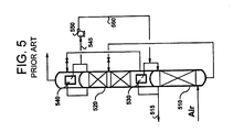
- a column system for the production of high pressure nitrogen with nitrogen liquid reflux pumped from the low pressure column to the high pressure column has been described in US-A- 5,098,457, and it is shown in Figure 5.
- air is introduced to high pressure column 510 and high pressure nitrogen product is withdrawn from the top of this column as stream 515.
- High pressure column 510 is heat integrated with low pressure column 520 through reboiler-condenser 530.
- Nitrogen overhead from the top of low pressure column 520 is condensed in condenser 540 and a part of this condensate in stream 545 is pumped using pump 550 back to high pressure column 510 as additional reflux 560, thus increasing the recovery of high pressure nitrogen in stream 515.
- An object of the present invention is to introduce low pressure nitrogen reflux into a distillation column that operates at a higher pressure without using pumps. More specifically, the present invention provides a method of separating air to produce nitrogen and/or oxygen in a system having at least one high pressure column, at least one low pressure column, and a reboiler-condenser, the method comprising generating a high pressure nitrogen stream from the high pressure column, and using energy from the high pressure nitrogen stream to provide nitrogen reflux to the high pressure column.
- the method according to one embodiment of the present invention comprises generating a high pressure nitrogen vapour stream and condensing a portion of the high pressure nitrogen vapour stream to form a high pressure nitrogen liquid stream which is reduced in pressure by transferring it to a reflux vessel, where it is collected, then using a portion of the high pressure vapour stream not condensed to pressurize the reflux vessel to a pressure equal to the high pressure column and cause the nitrogen liquid collected therein to flow into the high pressure column under force of pressurization coupled with the static head of the nitrogen liquid.
- the high pressure nitrogen vapour stream may optionally be expanded prior to condensing it to form the low pressure nitrogen liquid stream. This stream, after expansion and condensing, may then be further reduced in pressure and transferred to the reflux vessel.
- the method of the present invention comprises generating a high pressure nitrogen vapour stream, dividing the high pressure nitrogen vapour stream into two streams, one of which is condensed to form a nitrogen liquid stream, and the other of which is combined with the thus formed nitrogen liquid stream to form a two-phase mixture which is passed to a raised reflux vessel wherein the nitrogen liquid is collected and refluxed back to the high pressure column.
- the present invention also provides a method of separating air to produce nitrogen and/or oxygen in a system having at least one high pressure column, at least one low pressure column, and a reboiler-condenser located in the bottom of the low pressure column, comprising the steps of generating a first high pressure nitrogen vapour stream and a second high pressure nitrogen vapour stream from the high pressure column, condensing the first high pressure nitrogen stream to form a high pressure nitrogen liquid stream, dividing the high pressure nitrogen liquid stream into a low pressure column liquid reflux stream and a high pressure column liquid reflux stream, and using the second high pressure nitrogen vapour stream to supply energy to cause the passage of the high pressure column liquid reflux stream to the high pressure column.
- Another embodiment of the present invention comprises the steps of generating a high pressure nitrogen vapour stream from the high pressure column, dividing the high pressure nitrogen vapour stream from the generating step into a first high pressure nitrogen vapour stream and a second high pressure nitrogen vapour stream, condensing the first high pressure nitrogen vapour stream in a reboiler-condenser at the bottom of the low pressure column to form a high pressure nitrogen liquid stream, dividing the high pressure nitrogen liquid stream into a low pressure column liquid reflux stream and a high pressure column liquid reflux stream, and using the second high pressure nitrogen vapour stream to supply energy to cause the passage of the high pressure column liquid reflux stream to the high pressure column.
- Still another embodiment comprises a method of separating air to produce nitrogen and/or oxygen in a system having at least one high pressure column, at least one low pressure column, and a condenser, the method comprising the steps of withdrawing a high pressure nitrogen vapour stream from the high pressure column, withdrawing a low pressure nitrogen vapour stream from the low pressure column, condensing the low pressure nitrogen vapour stream to form a low pressure nitrogen liquid stream, transferring the low pressure nitrogen liquid stream to a reflux vessel that is at a transfer pressure less than the pressure of the high pressure column, and passing a portion of the high pressure nitrogen vapour stream to the reflux vessel to increase the pressure within the reflux vessel to a pressure equal to the high pressure column whereby the nitrogen liquid in the reflux vessel is passed to the high pressure column.
- Yet another embodiment of the present invention is a system for separating air to produce nitrogen and/or oxygen comprising a high pressure column for producing a first high pressure nitrogen vapour stream and a second high pressure nitrogen vapour stream, a low pressure column for producing a low pressure nitrogen vapour product stream, a condenser to receive the first high pressure nitrogen stream to form a high pressure nitrogen liquid stream, and at least two reflux vessels in fluid communication with the high pressure column for receiving the high pressure nitrogen liquid stream from the condenser, wherein the second high pressure nitrogen vapour stream is in fluid communication with the at least two reflux vessels to provide pressurization of the vessels.
- Still yet another embodiment is a system for separating air to produce nitrogen and/or oxygen comprising a high pressure column for producing a first high pressure nitrogen vapour stream, a low pressure column for producing a low pressure nitrogen vapour product stream, a condenser to receive the first high pressure nitrogen stream to form a high pressure nitrogen liquid stream, and a reflux vessel in fluid communication with the high pressure column for receiving the high pressure nitrogen liquid stream from the condenser, wherein the reflux vessel is disposed above the high pressure column at a height sufficient to generate a static head pressure necessary to deliver the high pressure nitrogen liquid stream from the reflux vessel to the top of the high pressure column.
- Yet still another embodiment of the present invention is a system for separating air to produce nitrogen and/or oxygen, comprising a high pressure column for producing a high pressure nitrogen vapour stream, a low pressure column for producing a low pressure nitrogen vapour product stream, a condenser to condense the low pressure nitrogen vapour product stream, and a reflux vessel in fluid communication with both columns for receiving the low pressure nitrogen liquid stream from the low pressure column and the high pressure nitrogen vapour stream from the high pressure column, wherein the reflux vessel is disposed above the high pressure column at a height sufficient to generate a static head pressure necessary to deliver the high pressure nitrogen liquid stream from the reflux vessel to the top of the high pressure column.
- the present invention finds primary utility in a cryogenic air separation process for oxygen and nitrogen production.
- the invention provides a method of transferring nitrogen liquid as a reflux to a column that is at a higher pressure than the nitrogen liquid, where energy from the higher-pressure nitrogen vapour is used to facilitate the transfer.
- the higher-pressure nitrogen vapour has a pressure not lower than the pressure on top of the column to which the nitrogen liquid is transferred.
- One embodiment of the current invention includes the separation of air in a system of columns having at least one high pressure column and at least one low pressure column built side-by-side, and a reboiler-condenser located in the bottom of the low pressure column.
- High pressure nitrogen liquid is transferred by a pressure difference to a reflux vessel that is at a lower pressure during the transfer. When this high-pressure nitrogen reaches the vessel, its pressure is reduced by the pressure drop necessary for the transfer.
- the pressure of the reflux vessel is increased by introduction of high pressure nitrogen vapour, preferably from the top of the high pressure column, thus allowing the nitrogen liquid to be returned to the high pressure column as reflux.
- high pressure nitrogen vapour is condensed in the reboiler-condenser to supply the necessary boilup for the low pressure column and to form high pressure nitrogen liquid.
- Compressed air purified from water and carbon dioxide and cooled to a cryogenic temperature, is introduced as stream 600 to high pressure column 605.
- Compressed air stream 600 is separated in column 605 into a high pressure nitrogen vapour overhead vapour stream 610, and an oxygen enriched liquid stream 615.
- Oxygen enriched liquid stream 615 carries a liquid mixture of oxygen and nitrogen to low pressure column 620, where it is separated into the final products, including gaseous oxygen product stream 630, and/or liquid oxygen product stream 635.
- a portion of high pressure nitrogen overhead vapour stream 610 is fed as stream 640 to reboiler-condenser 645 in column 620, where it is condensed to form nitrogen liquid stream 650.
- a portion of nitrogen liquid stream 650 is supplied as reflux to low pressure column 620 as stream 655, and the remaining portion (stream 660) is fed in turn to reflux vessels 665 and 670.
- Important to the invention is the periodic switching of stream 660 to fill vessels 665 and 670 with nitrogen liquid to provide a constant source of nitrogen liquid to the top of high pressure column 605. Specifically, while one vessel, e.g. 670, is being filled, the other, e.g. 665, is emptying its nitrogen liquid to the top of high pressure column 605.
- vessel 665 is filled with nitrogen liquid from stream 660
- displaced nitrogen vapour is vented from vessel 665 via nitrogen vapour stream 680 to be combined with nitrogen stream 625 to form low-pressure nitrogen product stream 685.
- high pressure nitrogen vapour is introduced to vessel 670 (which has already been filled with nitrogen liquid) via nitrogen vapour stream 675 to increase the pressure in vessel 670 and cause the nitrogen liquid therein to drain into high pressure column 605 via nitrogen liquid stream 690.
- vessel 670 Once vessel 670 is emptied and vessel 665 is filled, nitrogen liquid from stream 660 is directed to vessel 670 and high pressure nitrogen vapour from stream 675 is passed into vessel 665 causing its pressure to increase which causes its nitrogen liquid to drain into the high pressure column via nitrogen liquid stream 690.
- This alternating filiing/pressurizing/draining process continues and results in a constant supply of nitrogen to high pressure column 605.
- the high pressure nitrogen stream used to pressurize each of the vessels brings those vessels to the same pressure as the high pressure column. That pressurization, coupled with the head of the liquid in each vessel, causes those vessels to empty (when the appropriate valves are opened) into the high pressure column as reflux.
- each vessel is filled with high pressure nitrogen vapour before it is refilled with nitrogen liquid from stream 660.
- the nitrogen which is purged from each vessel 665, 670 may be vented via nitrogen vapour stream 680 or it could be expanded (not shown) in the low-pressure nitrogen product stream 685, to recover refrigeration.
- system may also contain a side rectifier off low pressure column 620 to produce argon. This modification is not shown in Figure 6.
- high pressure nitrogen liquid may also be transferred to a reflux vessel using high pressure nitrogen vapour lift.
- a vapour lift transfer high-pressure nitrogen vapour is injected into a nitrogen liquid stream to form cavities of nitrogen vapour within the nitrogen liquid (in other words, bubbling nitrogen vapour into the nitrogen liquid).
- the bubbles travel up the nitrogen liquid stream and some of the nitrogen liquid is carried with them.
- the introduction of the nitrogen vapour creates a two-phase mixture.
- the nitrogen vapour (bubbles) becomes disengaged from the liquid when the two-phase mixture reaches the reflux vessel.
- the reflux vessel is located high enough in the system so that nitrogen liquid can be returned back to the high pressure column at a sufficiently high pressure achieved by using static head.
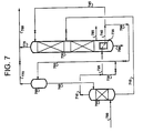
- Such an arrangement is shown schematically in Figure 7.
- a compressed air stream 700 purified from water and carbon dioxide and cooled down to a cryogenic temperature, is introduced to high pressure column 705.
- the compressed air stream 700 is separated in column 705 into high-pressure nitrogen overhead vapour stream 710 and oxygen enriched liquid stream 715.
- Oxygen enriched liquid stream 715 is fed to low pressure column 720.
- High pressure nitrogen vapour stream 710 is divided into two streams: major stream 725 and minor stream 730.
- the high pressure nitrogen vapour in major stream 725 is condensed in reboiler-condenser 735, thus providing boilup for low pressure column 720.
- Condensed nitrogen liquid stream 740 leaving reboiler-condenser 735 is divided into two streams: low pressure column reflux nitrogen liquid stream 745 and high pressure column reflux nitrogen liquid stream 750.
- High pressure column 705 reflux nitrogen liquid stream 750 is first passed to reflux vessel 760 via stream 755. Reflux is fed from the raised reflux vessel 760 to high pressure column 705 via nitrogen liquid stream 765 using static head.
- High pressure nitrogen vapour is injected into nitrogen liquid stream 750 from reboiler-condenser 735 via high pressure nitrogen vapour stream 730, providing vapour lift in nitrogen liquid stream 750 to form two-phase nitrogen stream 755.
- the high pressure nitrogen vapour is separated from nitrogen liquid in vessel 760.
- Low pressure nitrogen vapour stream 770 exiting the top of reflux vessel 760 joins low pressure nitrogen vapour stream 775 to yield a final low-pressure nitrogen vapour product stream 780.
- the other products from the low pressure column 720 are gaseous oxygen stream 785 and/or liquid oxygen stream 790.
- High pressure column 705 is fed high pressure nitrogen liquid from vessel 760 under the force of gravity; i.e. sufficient static head is generated in vessel 760 to provide nitrogen liquid to column 705.
- high pressure nitrogen vapour is used to increase the potential energy of the nitrogen liquid.
- this is done by increasing the pressure in the reflux vessel(s).
- this is accomplished by providing a vapour lift.
- the high pressure nitrogen vapour is ultimately vented to the low pressure nitrogen vapour liquid stream.
- the lost pressure of the high pressure nitrogen vapour provides the energy for nitrogen liquid transfer. Part of this energy can be recovered by using an expander (not shown).
- the present invention may also be used in other column arrangements, such as the one shown in Figure 4, where high pressure nitrogen vapour is expanded, prior to its condensation, and nitrogen liquid at an intermediate pressure is transferred back to the high-pressure column as a reflux.
- the present invention could be used in the column arrangement illustrated in Figure 5, to transfer nitrogen reflux from the low-pressure column to the high pressure column without a pump.
- Figure 8 shows the column system for production of nitrogen and/or oxygen, with nitrogen expansion and a dual reboiler as in Figure 4, except that the nitrogen liquid pump 450 has been replaced by reflux vessels 865, 870 and associated valves and lines. As described previously in reference to Figure 6, these two tanks work intermittently, i.e., one of them is being filled with nitrogen liquid while the other is drained to the high pressure column via line 872 or 874, connecting to line 876. High-pressure nitrogen gas is provided to each vessel intermittently (to increase its pressure) from the top of high pressure column 410 via line 880 and then 882 or 884. Lower pressure nitrogen is vented intermittently via lines 892 and 894 (while each corresponding vessel is filled).
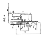
- Figure 9 shows the column system for production of nitrogen and/or oxygen, with nitrogen expansion and a dual reboiler as in Figure 4, except that the nitrogen liquid pump 450 has been replaced by tank 960 and associated lines.
- low pressure nitrogen liquid in line 446 is "vapour lifted” by high pressure nitrogen vapour in line 948 up line 950 to vessel 960.
- vessel 960 both phases separate; vapour phase leaves from the top in line 970; liquid phase is fed back (utilizing static pressure) to high pressure column 410 via line 965 as reflux.
- Figure 10 shows the column system for production of nitrogen, with nitrogen liquid transferred from low pressure column 520 to high pressure column 510, as in Figure 5, except that the nitrogen liquid pump 550 of Figure 5 has been replaced by tanks 1065, 1070 and associated valves and lines. As described previously with reference to Figure 6, these two tanks work intermittently, i.e., one of them is being filled with nitrogen liquid, while the other is drained to the high pressure column via line 1072 or 1074, connecting to line 560. High-pressure nitrogen gas is provided to each vessel intermittently (to increase its pressure) from the top of the high pressure column via line 1080 and then 1082 or 1084. Lower pressure nitrogen is vented intermittently via lines 1092 and 1094 (while each corresponding vessel is filled).
- the power used for transferring nitrogen liquid is about 0.6% of MAC (main air compressor) power, or 155 kW for a plant producing 2700 short tons (2450 tonnes) of oxygen per day.
- the capital cost of the reflux tanks depends on their size and the size is a function of the plant size and the frequency of switching. Some examples of tank sizes are given in Table 1.
- Reflux tank volume (m 3 ) as a function of plant size and the frequency of switching between the tanks Time, minutes Oxygen production, short ton / day (tonnes/day) 300 700 1500 2700 30 23.5 (21.3) 54.8 (49.7) 117.5 (106.6) 211.5 (191.9) 20 15.7 (14.2) 36.6 (33.2) 78.3 (71.0) 141.0 (127.9) 10 7.8 (7.1) 18.3 (16.6) 39.2 (35.6) 70.5 (64.0) 5 3.9 (3.5) 9.1 (8.3) 19.6 (17.8) 35.3 (32.0) 1 0.8 (0.7) 1.8 (1.6) 3.9 (3.5) 7.0 (6.4)
Landscapes
- Engineering & Computer Science (AREA)
- Physics & Mathematics (AREA)
- Mechanical Engineering (AREA)
- Thermal Sciences (AREA)
- General Engineering & Computer Science (AREA)
- Separation By Low-Temperature Treatments (AREA)
Abstract
Description
- This invention relates generally to air separation and more specifically to cryogenic air separation and nitrogen and/or oxygen production.
- Frequently, in a column system for air separation, there is a need to introduce low-pressure nitrogen liquid to a high pressure column as reflux. Examples of column systems where this occurs include:
- Side-by-side column arrangements for the production of nitrogen and/or oxygen;
- Column systems for the production of nitrogen and/or oxygen with dual reboiler and nitrogen expansion; and
- Column systems for the production of high pressure nitrogen with nitrogen liquid reflux pumped from the low pressure column to the high pressure column.
- In a typical air separation unit, for example the configuration shown in Figure 1, there are at least two distillation columns: a
high pressure column 110, and alow pressure column 120. These columns are heat integrated through reboiler-condenser 130 and the low pressure column is usually built on top of the high pressure column. - With the increasing trend toward higher efficiency distillation and higher purity of products, the height of the distillation column in such a configuration increases. The height of the combined high pressure-low pressure column system ultimately becomes so tall that the design of the entire system is prohibitively expensive. Stacking the columns is also not typically desired for larger plants, where the diameters of the columns are large and the columns are heavy.
- To avoid these problems, conventional high pressure and low pressure columns can be built side-by-side. The reboiler-condenser can be located on top of the high pressure column (such as the configuration shown in Figure 2) or in the bottom of the low pressure column (shown in Figure 3). In both of these cases a pump is necessary. According to US-A-6,148,637, and as shown in Figure 2, liquid oxygen in
stream 240 is pumped, usingpump 250, from the bottom oflow pressure column 220 toreboiler 230 located on top ofhigh pressure column 210. - US-A-6,148,637 discloses a three component system, comprised of a lower pressure column, a higher pressure column, and a heat exchanger. Included in this system is a pump for transporting liquid from the bottom of the lower pressure column to a vaporizer-condenser at the top of the higher pressure column.
- As illustrated in Figure 3, nitrogen liquid in
stream 360 is pumped, usingpump 350, from reboiler-condenser 330 located in the bottom oflow pressure column 320 back to the top ofhigh pressure column 310 as reflux. Usually two pumps instead of one are installed for the same service - a working pump and an idle nitrogen liquid pump that serves as a spare. Cryogenic liquid pumps are expensive, require periodic maintenance and, because they contain moving parts, are more likely to fail than stationary equipment. - A column system for the production of nitrogen and/or oxygen with a dual reboiler and nitrogen expansion has been described in US-A-4,796,431, and is shown in Figure 4. In this arrangement, air is introduced to
high pressure column 410 and product nitrogen and oxygen are withdrawn fromlow pressure column 420. The columns are heat integrated by lower reboiler-condenser 430 and upper reboiler-condenser 440. Nitrogen instream 432 from the top ofhigh pressure column 410 is divided intostreams Stream 436 is expanded inexpander 438, thus creating necessary refrigeration. The output ofexpander 438 is then condensed in upper reboiler-condenser 440 and the resultingstream 442 is divided intostreams Stream 444 is then fed to the top of thelow pressure column 420 as reflux.Stream 446 is directed to the high pressure column as additional reflux. Because its pressure was reduced by prior expansion, however,stream 446 needs to be pumped using pump 450. - A column system for the production of high pressure nitrogen with nitrogen liquid reflux pumped from the low pressure column to the high pressure column has been described in US-A- 5,098,457, and it is shown in Figure 5. In this arrangement, air is introduced to
high pressure column 510 and high pressure nitrogen product is withdrawn from the top of this column asstream 515.High pressure column 510 is heat integrated withlow pressure column 520 through reboiler-condenser 530. Nitrogen overhead from the top oflow pressure column 520 is condensed incondenser 540 and a part of this condensate instream 545 is pumped usingpump 550 back tohigh pressure column 510 asadditional reflux 560, thus increasing the recovery of high pressure nitrogen instream 515. - An object of the present invention is to introduce low pressure nitrogen reflux into a distillation column that operates at a higher pressure without using pumps. More specifically, the present invention provides a method of separating air to produce nitrogen and/or oxygen in a system having at least one high pressure column, at least one low pressure column, and a reboiler-condenser, the method comprising generating a high pressure nitrogen stream from the high pressure column, and using energy from the high pressure nitrogen stream to provide nitrogen reflux to the high pressure column.
- The method according to one embodiment of the present invention comprises generating a high pressure nitrogen vapour stream and condensing a portion of the high pressure nitrogen vapour stream to form a high pressure nitrogen liquid stream which is reduced in pressure by transferring it to a reflux vessel, where it is collected, then using a portion of the high pressure vapour stream not condensed to pressurize the reflux vessel to a pressure equal to the high pressure column and cause the nitrogen liquid collected therein to flow into the high pressure column under force of pressurization coupled with the static head of the nitrogen liquid. The high pressure nitrogen vapour stream may optionally be expanded prior to condensing it to form the low pressure nitrogen liquid stream. This stream, after expansion and condensing, may then be further reduced in pressure and transferred to the reflux vessel.
- In an alternate embodiment, the method of the present invention comprises generating a high pressure nitrogen vapour stream, dividing the high pressure nitrogen vapour stream into two streams, one of which is condensed to form a nitrogen liquid stream, and the other of which is combined with the thus formed nitrogen liquid stream to form a two-phase mixture which is passed to a raised reflux vessel wherein the nitrogen liquid is collected and refluxed back to the high pressure column.
- The present invention also provides a method of separating air to produce nitrogen and/or oxygen in a system having at least one high pressure column, at least one low pressure column, and a reboiler-condenser located in the bottom of the low pressure column, comprising the steps of generating a first high pressure nitrogen vapour stream and a second high pressure nitrogen vapour stream from the high pressure column, condensing the first high pressure nitrogen stream to form a high pressure nitrogen liquid stream, dividing the high pressure nitrogen liquid stream into a low pressure column liquid reflux stream and a high pressure column liquid reflux stream, and using the second high pressure nitrogen vapour stream to supply energy to cause the passage of the high pressure column liquid reflux stream to the high pressure column.
- Another embodiment of the present invention comprises the steps of generating a high pressure nitrogen vapour stream from the high pressure column, dividing the high pressure nitrogen vapour stream from the generating step into a first high pressure nitrogen vapour stream and a second high pressure nitrogen vapour stream, condensing the first high pressure nitrogen vapour stream in a reboiler-condenser at the bottom of the low pressure column to form a high pressure nitrogen liquid stream, dividing the high pressure nitrogen liquid stream into a low pressure column liquid reflux stream and a high pressure column liquid reflux stream, and using the second high pressure nitrogen vapour stream to supply energy to cause the passage of the high pressure column liquid reflux stream to the high pressure column.
- Still another embodiment comprises a method of separating air to produce nitrogen and/or oxygen in a system having at least one high pressure column, at least one low pressure column, and a condenser, the method comprising the steps of withdrawing a high pressure nitrogen vapour stream from the high pressure column, withdrawing a low pressure nitrogen vapour stream from the low pressure column, condensing the low pressure nitrogen vapour stream to form a low pressure nitrogen liquid stream, transferring the low pressure nitrogen liquid stream to a reflux vessel that is at a transfer pressure less than the pressure of the high pressure column, and passing a portion of the high pressure nitrogen vapour stream to the reflux vessel to increase the pressure within the reflux vessel to a pressure equal to the high pressure column whereby the nitrogen liquid in the reflux vessel is passed to the high pressure column.
- Yet another embodiment of the present invention is a system for separating air to produce nitrogen and/or oxygen comprising a high pressure column for producing a first high pressure nitrogen vapour stream and a second high pressure nitrogen vapour stream, a low pressure column for producing a low pressure nitrogen vapour product stream, a condenser to receive the first high pressure nitrogen stream to form a high pressure nitrogen liquid stream, and at least two reflux vessels in fluid communication with the high pressure column for receiving the high pressure nitrogen liquid stream from the condenser, wherein the second high pressure nitrogen vapour stream is in fluid communication with the at least two reflux vessels to provide pressurization of the vessels.
- Still yet another embodiment is a system for separating air to produce nitrogen and/or oxygen comprising a high pressure column for producing a first high pressure nitrogen vapour stream, a low pressure column for producing a low pressure nitrogen vapour product stream, a condenser to receive the first high pressure nitrogen stream to form a high pressure nitrogen liquid stream, and a reflux vessel in fluid communication with the high pressure column for receiving the high pressure nitrogen liquid stream from the condenser, wherein the reflux vessel is disposed above the high pressure column at a height sufficient to generate a static head pressure necessary to deliver the high pressure nitrogen liquid stream from the reflux vessel to the top of the high pressure column.
- Yet still another embodiment of the present invention is a system for separating air to produce nitrogen and/or oxygen, comprising a high pressure column for producing a high pressure nitrogen vapour stream, a low pressure column for producing a low pressure nitrogen vapour product stream, a condenser to condense the low pressure nitrogen vapour product stream, and a reflux vessel in fluid communication with both columns for receiving the low pressure nitrogen liquid stream from the low pressure column and the high pressure nitrogen vapour stream from the high pressure column, wherein the reflux vessel is disposed above the high pressure column at a height sufficient to generate a static head pressure necessary to deliver the high pressure nitrogen liquid stream from the reflux vessel to the top of the high pressure column.
- The following is a description by way of example only and with reference to the accompanying drawings of presently preferred embodiments of the invention. In the drawings:
- Figure 1 is a schematic illustration of a one column arrangement according to the prior art;
- Figure 2 is a schematic illustration of a side-by-side arrangement according to the prior art;
- Figure 3 is a schematic illustration of an alternative side-by-side arrangement according to the prior art;
- Figure 4 is a schematic illustration of an alternative one column arrangement according to the prior art;
- Figure 5 is a schematic illustration of still another one column arrangement according to the prior art;
- Figure 6 is a schematic illustration of an embodiment of the present invention where two reflux vessels are disposed above the top of the high pressure column to increase the potential energy of the nitrogen liquid from the low pressure column;
- Figure 7 is a schematic illustration of another embodiment of the present invention where high pressure nitrogen vapour from the high pressure column is used to vapour lift nitrogen liquid from the low pressure column to a reflux vessel;
- Figure 8 is a schematic illustration of an alternative embodiment of the present invention where two reflux vessels are disposed above the top of the high pressure column in a one column arrangement to increase the potential energy of the nitrogen liquid from the low pressure column;
- Figure 9 is a schematic illustration of another embodiment of the present invention where high pressure nitrogen vapour from the high pressure column is used to vapour lift nitrogen liquid from the low pressure column to a reflux vessel; and
- Figure 10 is a schematic illustration of still another embodiment of the present invention where two reflux vessels are disposed above the top of the high pressure column in a one column arrangement to increase the potential energy of the nitrogen liquid from the low pressure column.
-
- The present invention finds primary utility in a cryogenic air separation process for oxygen and nitrogen production. The invention provides a method of transferring nitrogen liquid as a reflux to a column that is at a higher pressure than the nitrogen liquid, where energy from the higher-pressure nitrogen vapour is used to facilitate the transfer. The higher-pressure nitrogen vapour has a pressure not lower than the pressure on top of the column to which the nitrogen liquid is transferred.
- One embodiment of the current invention includes the separation of air in a system of columns having at least one high pressure column and at least one low pressure column built side-by-side, and a reboiler-condenser located in the bottom of the low pressure column. High pressure nitrogen liquid is transferred by a pressure difference to a reflux vessel that is at a lower pressure during the transfer. When this high-pressure nitrogen reaches the vessel, its pressure is reduced by the pressure drop necessary for the transfer. After the transfer, the pressure of the reflux vessel is increased by introduction of high pressure nitrogen vapour, preferably from the top of the high pressure column, thus allowing the nitrogen liquid to be returned to the high pressure column as reflux. In this configuration, high pressure nitrogen vapour is condensed in the reboiler-condenser to supply the necessary boilup for the low pressure column and to form high pressure nitrogen liquid.
- Although it is possible to use just one vessel, it is often more convenient to use two or more reflux vessels. In such an arrangement (as shown in Figure 6), two reflux vessels are used and one of the vessels is filled while the other supplies reflux to the high pressure column. Through this rotation, the high pressure column receives continuous, uninterrupted flow of nitrogen liquid reflux. These vessels may operate in series or in parallel. Alternatively, the two vessels may be contained within one larger vessel forming compartments, separated by dividing walls.
- A more detailed description of the preferred embodiment of the current invention is now discussed with reference to Figure 6. Compressed air, purified from water and carbon dioxide and cooled to a cryogenic temperature, is introduced as
stream 600 tohigh pressure column 605.Compressed air stream 600 is separated incolumn 605 into a high pressure nitrogen vapouroverhead vapour stream 610, and an oxygen enrichedliquid stream 615. Oxygen enrichedliquid stream 615 carries a liquid mixture of oxygen and nitrogen tolow pressure column 620, where it is separated into the final products, including gaseousoxygen product stream 630, and/or liquidoxygen product stream 635. - A portion of high pressure nitrogen
overhead vapour stream 610 is fed asstream 640 to reboiler-condenser 645 incolumn 620, where it is condensed to formnitrogen liquid stream 650. A portion ofnitrogen liquid stream 650 is supplied as reflux tolow pressure column 620 asstream 655, and the remaining portion (stream 660) is fed in turn to refluxvessels - Important to the invention is the periodic switching of
stream 660 to fillvessels high pressure column 605. Specifically, while one vessel, e.g. 670, is being filled, the other, e.g. 665, is emptying its nitrogen liquid to the top ofhigh pressure column 605. - For example, while
vessel 665 is filled with nitrogen liquid fromstream 660, displaced nitrogen vapour is vented fromvessel 665 vianitrogen vapour stream 680 to be combined withnitrogen stream 625 to form low-pressurenitrogen product stream 685. At the same time, whilevessel 665 is filling with nitrogen liquid, high pressure nitrogen vapour is introduced to vessel 670 (which has already been filled with nitrogen liquid) vianitrogen vapour stream 675 to increase the pressure invessel 670 and cause the nitrogen liquid therein to drain intohigh pressure column 605 vianitrogen liquid stream 690. Oncevessel 670 is emptied andvessel 665 is filled, nitrogen liquid fromstream 660 is directed tovessel 670 and high pressure nitrogen vapour fromstream 675 is passed intovessel 665 causing its pressure to increase which causes its nitrogen liquid to drain into the high pressure column vianitrogen liquid stream 690. This alternating filiing/pressurizing/draining process continues and results in a constant supply of nitrogen tohigh pressure column 605. The high pressure nitrogen stream used to pressurize each of the vessels brings those vessels to the same pressure as the high pressure column. That pressurization, coupled with the head of the liquid in each vessel, causes those vessels to empty (when the appropriate valves are opened) into the high pressure column as reflux. - During the process of filling and emptying
vessels stream 660. The nitrogen which is purged from eachvessel nitrogen vapour stream 680 or it could be expanded (not shown) in the low-pressurenitrogen product stream 685, to recover refrigeration. - In an alternative arrangement from that shown in Figure 6, the system may also contain a side rectifier off
low pressure column 620 to produce argon. This modification is not shown in Figure 6. - In another embodiment of the present invention, high pressure nitrogen liquid may also be transferred to a reflux vessel using high pressure nitrogen vapour lift. In a vapour lift transfer, high-pressure nitrogen vapour is injected into a nitrogen liquid stream to form cavities of nitrogen vapour within the nitrogen liquid (in other words, bubbling nitrogen vapour into the nitrogen liquid). The bubbles travel up the nitrogen liquid stream and some of the nitrogen liquid is carried with them. In effect, the introduction of the nitrogen vapour creates a two-phase mixture. The nitrogen vapour (bubbles) becomes disengaged from the liquid when the two-phase mixture reaches the reflux vessel. The reflux vessel is located high enough in the system so that nitrogen liquid can be returned back to the high pressure column at a sufficiently high pressure achieved by using static head. Such an arrangement is shown schematically in Figure 7.
- Referring to Figure 7, a
compressed air stream 700, purified from water and carbon dioxide and cooled down to a cryogenic temperature, is introduced tohigh pressure column 705. Thecompressed air stream 700 is separated incolumn 705 into high-pressure nitrogen overhead vapour stream 710 and oxygen enriched liquid stream 715. Oxygen enriched liquid stream 715 is fed tolow pressure column 720. High pressure nitrogen vapour stream 710 is divided into two streams:major stream 725 andminor stream 730. The high pressure nitrogen vapour inmajor stream 725 is condensed in reboiler-condenser 735, thus providing boilup forlow pressure column 720. Condensednitrogen liquid stream 740 leaving reboiler-condenser 735 is divided into two streams: low pressure column refluxnitrogen liquid stream 745 and high pressure column refluxnitrogen liquid stream 750.High pressure column 705 refluxnitrogen liquid stream 750 is first passed to refluxvessel 760 viastream 755. Reflux is fed from the raisedreflux vessel 760 tohigh pressure column 705 vianitrogen liquid stream 765 using static head. - High pressure nitrogen vapour is injected into
nitrogen liquid stream 750 from reboiler-condenser 735 via high pressurenitrogen vapour stream 730, providing vapour lift innitrogen liquid stream 750 to form two-phase nitrogen stream 755. The high pressure nitrogen vapour is separated from nitrogen liquid invessel 760. Low pressure nitrogen vapour stream 770 exiting the top ofreflux vessel 760 joins low pressurenitrogen vapour stream 775 to yield a final low-pressure nitrogen vapour product stream 780. The other products from thelow pressure column 720 aregaseous oxygen stream 785 and/or liquid oxygen stream 790.High pressure column 705 is fed high pressure nitrogen liquid fromvessel 760 under the force of gravity; i.e. sufficient static head is generated invessel 760 to provide nitrogen liquid tocolumn 705. - In the embodiments shown in Figures 1-5, high pressure nitrogen vapour is used to increase the potential energy of the nitrogen liquid. In the case of the embodiment shown in Figure 6, this is done by increasing the pressure in the reflux vessel(s). In the case of the embodiment shown in Figure 7, this is accomplished by providing a vapour lift. In both cases, the high pressure nitrogen vapour is ultimately vented to the low pressure nitrogen vapour liquid stream. The lost pressure of the high pressure nitrogen vapour provides the energy for nitrogen liquid transfer. Part of this energy can be recovered by using an expander (not shown).
- The present invention may also be used in other column arrangements, such as the one shown in Figure 4, where high pressure nitrogen vapour is expanded, prior to its condensation, and nitrogen liquid at an intermediate pressure is transferred back to the high-pressure column as a reflux. Alternatively, the present invention could be used in the column arrangement illustrated in Figure 5, to transfer nitrogen reflux from the low-pressure column to the high pressure column without a pump. These embodiments are discussed in more detail below.
- Figure 8 shows the column system for production of nitrogen and/or oxygen, with nitrogen expansion and a dual reboiler as in Figure 4, except that the nitrogen liquid pump 450 has been replaced by
reflux vessels line line 876. High-pressure nitrogen gas is provided to each vessel intermittently (to increase its pressure) from the top ofhigh pressure column 410 vialine 880 and then 882 or 884. Lower pressure nitrogen is vented intermittently vialines 892 and 894 (while each corresponding vessel is filled). - Figure 9 shows the column system for production of nitrogen and/or oxygen, with nitrogen expansion and a dual reboiler as in Figure 4, except that the nitrogen liquid pump 450 has been replaced by
tank 960 and associated lines. As described previously in reference to Figure 7, low pressure nitrogen liquid inline 446 is "vapour lifted" by high pressure nitrogen vapour inline 948 upline 950 tovessel 960. Invessel 960, both phases separate; vapour phase leaves from the top inline 970; liquid phase is fed back (utilizing static pressure) tohigh pressure column 410 vialine 965 as reflux. - Figure 10 shows the column system for production of nitrogen, with nitrogen liquid transferred from
low pressure column 520 tohigh pressure column 510, as in Figure 5, except that thenitrogen liquid pump 550 of Figure 5 has been replaced bytanks line line 560. High-pressure nitrogen gas is provided to each vessel intermittently (to increase its pressure) from the top of the high pressure column vialine 1080 and then 1082 or 1084. Lower pressure nitrogen is vented intermittently vialines 1092 and 1094 (while each corresponding vessel is filled). - It has been determined that for the embodiment of the invention illustrated in Figure 6, the power used for transferring nitrogen liquid is about 0.6% of MAC (main air compressor) power, or 155 kW for a plant producing 2700 short tons (2450 tonnes) of oxygen per day. The capital cost of the reflux tanks depends on their size and the size is a function of the plant size and the frequency of switching. Some examples of tank sizes are given in Table 1.
Reflux tank volume (m3) as a function of plant size and the frequency of switching between the tanks Time, minutes Oxygen production, short ton / day (tonnes/day) 300 700 1500 2700 30 23.5 (21.3) 54.8 (49.7) 117.5 (106.6) 211.5 (191.9) 20 15.7 (14.2) 36.6 (33.2) 78.3 (71.0) 141.0 (127.9) 10 7.8 (7.1) 18.3 (16.6) 39.2 (35.6) 70.5 (64.0) 5 3.9 (3.5) 9.1 (8.3) 19.6 (17.8) 35.3 (32.0) 1 0.8 (0.7) 1.8 (1.6) 3.9 (3.5) 7.0 (6.4)
Claims (19)
- A method of separating air to produce nitrogen and/or oxygen in a system having at least one high pressure column (605) and at least one low pressure column (620) characterized in that energy from a high pressure nitrogen vapour stream (675) from the high pressure column (605) is used to provide nitrogen reflux (690) to the high pressure column (605).
- A method of Claim 1, wherein a portion (640) of a high pressure nitrogen vapour (610) stream from the high pressure column (605) is condensed (645) to form a high pressure nitrogen liquid stream (660), which is collected in a vessel (665, 670), and a portion (675) of the high pressure nitrogen vapour stream (610) not condensed is used to pressurize the vessel (665, 670) to cause the high pressure nitrogen liquid (660) collected in the vessel (665, 670) to flow into the high pressure column.
- A method of Claim 1, wherein a high pressure nitrogen vapour stream (710) from the high pressure column (705) is divided into two streams (725,730), one of said vapour streams (725) is condensed (735) to form a high pressure nitrogen liquid stream (750), and the other of said vapour streams (730) is combined with said liquid stream (750) to form a two-phase mixture (755), the two phase mixture (755) is passed to a reflux vessel (760), and nitrogen liquid (765) collected in the reflux vessel (760) is fed back to the high pressure column (705) as reflux under the force created by a static head in the reflux vessel (760).
- A method of Claim 1, wherein low pressure nitrogen vapour stream from the low pressure column is condensed (540) to form a low pressure nitrogen liquid stream (545); the low pressure nitrogen liquid stream (545) is fed to a reflux vessel (1065, 1070) that is at a transfer pressure less than the pressure of the high pressure column (510); and a portion (1080) of the high pressure nitrogen vapour stream is fed to the reflux vessel (1065, 1070) to increase the pressure within the reflux vessel (1065, 1070) to a pressure equal to the high pressure column (510) whereby the nitrogen liquid (1072, 1074) in the reflux vessel is passed to the high pressure column (510).
- A method of Claim 1, wherein first high pressure nitrogen vapour stream (436) and a second high pressure nitrogen vapour stream (880, 948) are removed from the high pressure column (410); said first vapour stream (436) is condensed (440) to form a high pressure nitrogen liquid stream (442); said liquid stream (442) is divided into a low pressure column liquid reflux stream (444) and a high pressure column liquid reflux stream (446); and said second vapour stream (880; 948) is used to supply energy to cause passage of said high pressure column liquid reflux stream (872, 874; 965) to the high pressure column (410).
- A method of Claim 5, wherein said first and second high pressure nitrogen vapour streams (640, 675) are provided by dividing a single high pressure nitrogen vapour stream (610) removed from the high pressure column (605).
- A method of Claim 6, wherein said first high pressure nitrogen vapour stream (436) is expanded (438) prior to condensation (440).
- A method of Claim 6, wherein said high pressure column liquid reflux stream (446) is fed to a reflux vessel (865, 870) that is at a transfer pressure less than the pressure of the high pressure column (410); and said second high pressure nitrogen vapour stream (880) is fed to the reflux vessel (865, 870) to increase the pressure within the reflux vessel (865, 870) to a pressure equal to the high pressure column (410) whereby the nitrogen liquid (872, 874) in the reflux vessel (865, 870) is passed to the high pressure column (410).
- A method of Claim 6, wherein said high pressure column liquid reflux stream (446) is fed to a first reflux vessel (865) that is at a transfer pressure less than the pressure of the high pressure column (410); said second high pressure nitrogen vapour stream (880) is fed (884) into the first reflux vessel (865) to increase the pressure within the first reflux vessel (865) to a pressure equal to the high pressure column (410) whereby the nitrogen liquid (872) in the first reflux vessel (865) is passed to the high pressure column (410; said high pressure column liquid reflux stream (446) is redirected into a second reflux vessel (870) that is at a transfer pressure less than the pressure of the high pressure column (410) while the pressure is increased on the first reflux vessel (865); said second high pressure nitrogen vapour stream (880) is redirected (882) into the second reflux vessel (870) to increase the pressure within the second reflux vessel (870) to a pressure equal to the high pressure column (410) whereby the nitrogen liquid (874) in the second reflux vessel (870) is passed to the high pressure column (410) while the high pressure column liquid reflux stream (446) is passed into the first reflux vessel (865); and said procedure is repeated whereby a constant supply of nitrogen liquid is supplied as reflux to the high pressure column (410).
- A method of Claim 6, wherein said second high pressure nitrogen vapour stream (948) and said high pressure column liquid reflux stream (446) are combined to form a two-phase stream (950); the two-phase stream (950) is fed to a reflux vessel (860); and the nitrogen liquid accumulated in the reflux vessel is fed, as the high pressure column liquid reflux stream (965), to the high pressure column (410).
- A method of Claim 10, wherein the nitrogen liquid (965) accumulated in the reflux vessel (960) is fed to the high pressure column (410) under a static head of nitrogen liquid accumulated in the reflux vessel (960).
- A method of any one of the preceding claims, wherein said condensation of high pressure nitrogen vapour is in a reboiler-condenser (645) located in the bottom of the low pressure column (620).
- A method of Claim 4, wherein said high pressure nitrogen vapour stream is divided into a first and second stream, the first stream providing said portion (1080) of the high pressure vapour stream and the second stream being condensed in a reboiler-condenser (530) located above the high pressure column (510) and returned to the high pressure column (510) as reflux.
- A method of Claim 4 or Claim 13, wherein said low pressure nitrogen vapour stream is condensed in a condenser (540) located above the low pressure column (520) and then divided into two streams, a first stream which is returned to the low pressure column (520) as reflux, and a second stream (545) which is fed to said reflux vessel (1065, 1070).
- A system for separating air to produce nitrogen and/or oxygen by a method of Claim 9, said system comprising:a high pressure column (605) for producing a first high pressure nitrogen vapour stream (640) and a second high pressure nitrogen vapour stream (610);a low pressure column (620) for producing a low pressure nitrogen vapour product stream (625);a condenser (645) to receive the first high pressure nitrogen vapour stream (640) to form a high pressure nitrogen liquid stream (660);at least two reflux vessels (665, 670) in fluid communication with said high pressure column (605) for receiving the high pressure nitrogen liquid stream (660) from said condenser (645) and providing reflux (690) to said high pressure column (605); andmeans for selectively feeding the second high pressure nitrogen vapour stream (675) to said at least two reflux vessels (665, 670) to provide pressurization of said vessels.
- A system of Claim 15, wherein said condenser (645) is located in the bottom of said low pressure column (620).
- A system for separating air to produce nitrogen and/or oxygen by a method of Claim 3, said system, comprising:wherein said reflux vessel (760) is disposed above said high pressure column (705) at a height sufficient to generate a static head pressure necessary to deliver the high pressure nitrogen liquid stream (765) from said reflux vessel (760) to the top of said high pressure column (705).a high pressure column (705) for producing a first high pressure nitrogen vapour stream (725) and a second high pressure nitrogen vapour stream (730);a low pressure column (720) for producing a low pressure nitrogen vapour stream (775),a condenser (735) to receive the first high pressure nitrogen vapour stream (725) to form a high pressure nitrogen liquid stream (750);a reflux vessel (760) in fluid communication with said high pressure column (705) to provide reflux (765) thereto; andvapour lift means for feeding the high pressure nitrogen liquid stream from said condenser to the reflux vessel (760) by mixing with said second high pressure nitrogen vapour stream (730);
- A system of Claim 17, wherein said condenser (735) is located in the bottom of said low pressure column (720).
- A system for separating air to produce nitrogen and/or oxygen by a method of Claim 4, said system comprising:wherein said reflux vessel (1065; 1070) is disposed above said high pressure column (510) at a height sufficient to generate a static head pressure necessary to deliver the high pressure nitrogen liquid stream (560) from said reflux vessel (1065; 1070) to the top of said high pressure column (510).a high pressure column (510) for producing a high pressure nitrogen vapour stream (1080);a low pressure column (520) for producing a low pressure nitrogen vapour stream,a condenser (540) to condense the low pressure nitrogen vapour product stream to form a low pressure nitrogen liquid stream (545), anda reflux vessel (1065; 1070) in fluid communication with both columns (510, 520) for receiving the low pressure nitrogen liquid stream (545) and the high pressure nitrogen vapour stream (1080) from the high pressure column (510) to provide a high pressure nitrogen liquid stream as reflux (560) to the high pressure column (510);
Applications Claiming Priority (2)
| Application Number | Priority Date | Filing Date | Title |
|---|---|---|---|
| US137973 | 2002-05-03 | ||
| US10/137,973 US6568208B1 (en) | 2002-05-03 | 2002-05-03 | System and method for introducing low pressure reflux to a high pressure column without a pump |
Publications (1)
| Publication Number | Publication Date |
|---|---|
| EP1363094A1 true EP1363094A1 (en) | 2003-11-19 |
Family
ID=22479860
Family Applications (1)
| Application Number | Title | Priority Date | Filing Date |
|---|---|---|---|
| EP03252651A Withdrawn EP1363094A1 (en) | 2002-05-03 | 2003-04-25 | System and method for introducing low pressure reflux to a high pressure column without a pump |
Country Status (2)
| Country | Link |
|---|---|
| US (1) | US6568208B1 (en) |
| EP (1) | EP1363094A1 (en) |
Families Citing this family (7)
| Publication number | Priority date | Publication date | Assignee | Title |
|---|---|---|---|---|
| DE102005006408A1 (en) * | 2005-02-11 | 2006-08-24 | Linde Ag | A method of separating trace components from a nitrogen-rich stream |
| FR2946735B1 (en) * | 2009-06-12 | 2012-07-13 | Air Liquide | APPARATUS AND METHOD FOR AIR SEPARATION BY CRYOGENIC DISTILLATION. |
| US8495882B2 (en) * | 2009-08-10 | 2013-07-30 | General Electric Company | Syngas cleanup section with carbon capture and hydrogen-selective membrane |
| US20130000351A1 (en) * | 2011-06-28 | 2013-01-03 | Air Liquide Process & Construction, Inc. | Production Of High-Pressure Gaseous Nitrogen |
| US9097459B2 (en) | 2011-08-17 | 2015-08-04 | Air Liquide Process & Construction, Inc. | Production of high-pressure gaseous nitrogen |
| SG11201506454TA (en) * | 2013-02-21 | 2015-09-29 | Gtc Technology Us Llc | Separation processes using divided columns |
| US20250189219A1 (en) * | 2023-12-06 | 2025-06-12 | Air Liquide Large Industries U.S. Lp | Method for pressurizing a liquid exiting a phase separator |
Citations (7)
| Publication number | Priority date | Publication date | Assignee | Title |
|---|---|---|---|---|
| DE849850C (en) * | 1944-01-27 | 1952-09-18 | Adolf Messer G M B H | Process for the separation of air |
| US4717410A (en) * | 1985-03-11 | 1988-01-05 | L'air Liquide, Societe Anonyme Pour L'etude Et L'exploitation Des Procedes Georges Claude | Process and installation for producing nitrogen under pressure |
| US4796431A (en) * | 1986-07-15 | 1989-01-10 | Erickson Donald C | Nitrogen partial expansion refrigeration for cryogenic air separation |
| DE3732363A1 (en) * | 1987-09-25 | 1989-04-06 | Linde Ag | Method and device for restarting a gas fractionation plant |
| US5337569A (en) * | 1992-03-24 | 1994-08-16 | L'air Liquide, Societe Anonyme Pour L'etude Et L'exploitation Des Procedes Georges Claude | Process and installation for the transfer of liquid |
| US6148637A (en) * | 1998-02-06 | 2000-11-21 | L'air Liquide, Societe Anonyme Pour L'etude Et L'exploitation Des Procedes Georges Claude | Air-distillation plant and corresponding cold box |
| US6295840B1 (en) * | 2000-11-15 | 2001-10-02 | Air Products And Chemicals, Inc. | Pressurized liquid cryogen process |
Family Cites Families (5)
| Publication number | Priority date | Publication date | Assignee | Title |
|---|---|---|---|---|
| US4595405A (en) * | 1984-12-21 | 1986-06-17 | Air Products And Chemicals, Inc. | Process for the generation of gaseous and/or liquid nitrogen |
| US5098457A (en) * | 1991-01-22 | 1992-03-24 | Union Carbide Industrial Gases Technology Corporation | Method and apparatus for producing elevated pressure nitrogen |
| US5386692A (en) * | 1994-02-08 | 1995-02-07 | Praxair Technology, Inc. | Cryogenic rectification system with hybrid product boiler |
| US5513497A (en) * | 1995-01-20 | 1996-05-07 | Air Products And Chemicals, Inc. | Separation of fluid mixtures in multiple distillation columns |
| EP0955509B1 (en) * | 1998-04-30 | 2004-12-22 | Linde Aktiengesellschaft | Process and apparatus to produce high purity nitrogen |
-
2002
- 2002-05-03 US US10/137,973 patent/US6568208B1/en not_active Expired - Fee Related
-
2003
- 2003-04-25 EP EP03252651A patent/EP1363094A1/en not_active Withdrawn
Patent Citations (7)
| Publication number | Priority date | Publication date | Assignee | Title |
|---|---|---|---|---|
| DE849850C (en) * | 1944-01-27 | 1952-09-18 | Adolf Messer G M B H | Process for the separation of air |
| US4717410A (en) * | 1985-03-11 | 1988-01-05 | L'air Liquide, Societe Anonyme Pour L'etude Et L'exploitation Des Procedes Georges Claude | Process and installation for producing nitrogen under pressure |
| US4796431A (en) * | 1986-07-15 | 1989-01-10 | Erickson Donald C | Nitrogen partial expansion refrigeration for cryogenic air separation |
| DE3732363A1 (en) * | 1987-09-25 | 1989-04-06 | Linde Ag | Method and device for restarting a gas fractionation plant |
| US5337569A (en) * | 1992-03-24 | 1994-08-16 | L'air Liquide, Societe Anonyme Pour L'etude Et L'exploitation Des Procedes Georges Claude | Process and installation for the transfer of liquid |
| US6148637A (en) * | 1998-02-06 | 2000-11-21 | L'air Liquide, Societe Anonyme Pour L'etude Et L'exploitation Des Procedes Georges Claude | Air-distillation plant and corresponding cold box |
| US6295840B1 (en) * | 2000-11-15 | 2001-10-02 | Air Products And Chemicals, Inc. | Pressurized liquid cryogen process |
Non-Patent Citations (1)
| Title |
|---|
| RHODE W.: "Luftzerlegungsanlage mit Wechselspeicherung für variable Sauerstofflierferung", January 1984 (1984-01-01), pages 18 - 20, XP000601860 * |
Also Published As
| Publication number | Publication date |
|---|---|
| US6568208B1 (en) | 2003-05-27 |
Similar Documents
| Publication | Publication Date | Title |
|---|---|---|
| EP0496355B1 (en) | Method and apparatus for producing elevated pressure nitrogen | |
| JP4331460B2 (en) | Method and apparatus for producing krypton and / or xenon by low temperature air separation | |
| EP0147460B1 (en) | Cryogenic triple-pressure air separation with lp-to-mp latent-heat-exchange | |
| US8448463B2 (en) | Cryogenic rectification method | |
| EP1134526A2 (en) | Process for the production of oxygen and nitrogen | |
| EP0172247A1 (en) | High pressure oxygen pumped lox rectifier | |
| EP0962732B1 (en) | Multiple column nitrogen generators with oxygen coproduction | |
| JPH102664A (en) | Low temperature distillating method for air flow of compressed raw material for manufacturing oxygen products of low purity and high purity | |
| EP0572962A1 (en) | Auxiliary column cryogenic rectification system and apparatus | |
| US8479535B2 (en) | Method and apparatus for producing high purity oxygen | |
| KR100240323B1 (en) | Method and apparatus for producing liquid products from air in various proportions | |
| US10443931B2 (en) | Method and device for the cryogenic decomposition of air | |
| JPH06210162A (en) | Ultralow temperature fractionation system with thermally unified argon column | |
| JP3545629B2 (en) | Cryogenic purification method and apparatus for producing ultra-high purity nitrogen and ultra-high purity oxygen | |
| US4715874A (en) | Retrofittable argon recovery improvement to air separation | |
| US6568208B1 (en) | System and method for introducing low pressure reflux to a high pressure column without a pump | |
| EP0725256A1 (en) | Process to remove nitrogen from natural gas | |
| JPH09113130A (en) | Air separating method by low-temperature distribution manufacturing ultra-high purity oxygen | |
| EP0532155B1 (en) | Cryogenic process for producing ultra high purity nitrogen | |
| US6269659B1 (en) | Method and installation for air distillation with production of argon | |
| EP0343421B1 (en) | Ultra pure liquid oxygen cycle | |
| EP0834712A2 (en) | Process to produce high pressure nitrogen using a higher pressure column and one or more lower pressure columns | |
| JP4002233B2 (en) | Low temperature separation method and apparatus for air | |
| JP2000356465A (en) | Low-temperature distillating system for separating air | |
| JP2013525719A (en) | Method and apparatus for separation of air by cryogenic distillation |
Legal Events
| Date | Code | Title | Description |
|---|---|---|---|
| PUAI | Public reference made under article 153(3) epc to a published international application that has entered the european phase |
Free format text: ORIGINAL CODE: 0009012 |
|
| AK | Designated contracting states |
Kind code of ref document: A1 Designated state(s): AT BE BG CH CY CZ DE DK EE ES FI FR GB GR HU IE IT LI LU MC NL PT RO SE SI SK TR |
|
| AX | Request for extension of the european patent |
Extension state: AL LT LV MK |
|
| 17P | Request for examination filed |
Effective date: 20031115 |
|
| AKX | Designation fees paid |
Designated state(s): AT BE BG CH CY CZ DE DK EE ES FI FR GB GR HU IE IT LI LU MC NL PT RO SE SI SK TR |
|
| STAA | Information on the status of an ep patent application or granted ep patent |
Free format text: STATUS: THE APPLICATION IS DEEMED TO BE WITHDRAWN |
|
| 18D | Application deemed to be withdrawn |
Effective date: 20090115 |