EP1363022A1 - Taumelscheibenvorrichtung für einen Kompressor - Google Patents
Taumelscheibenvorrichtung für einen Kompressor Download PDFInfo
- Publication number
- EP1363022A1 EP1363022A1 EP02010626A EP02010626A EP1363022A1 EP 1363022 A1 EP1363022 A1 EP 1363022A1 EP 02010626 A EP02010626 A EP 02010626A EP 02010626 A EP02010626 A EP 02010626A EP 1363022 A1 EP1363022 A1 EP 1363022A1
- Authority
- EP
- European Patent Office
- Prior art keywords
- arrangement
- wobble plate
- plate
- bearing
- swash plate
- Prior art date
- Legal status (The legal status is an assumption and is not a legal conclusion. Google has not performed a legal analysis and makes no representation as to the accuracy of the status listed.)
- Granted
Links
- 238000005524 ceramic coating Methods 0.000 claims abstract description 34
- 238000005096 rolling process Methods 0.000 claims abstract description 27
- 229910010293 ceramic material Inorganic materials 0.000 claims abstract description 17
- 229910000831 Steel Inorganic materials 0.000 claims description 15
- 239000010959 steel Substances 0.000 claims description 15
- 239000000919 ceramic Substances 0.000 claims description 9
- 238000004378 air conditioning Methods 0.000 claims description 6
- 238000006073 displacement reaction Methods 0.000 claims description 5
- 229910000838 Al alloy Inorganic materials 0.000 claims description 3
- 229910052581 Si3N4 Inorganic materials 0.000 claims description 3
- RVTZCBVAJQQJTK-UHFFFAOYSA-N oxygen(2-);zirconium(4+) Chemical compound [O-2].[O-2].[Zr+4] RVTZCBVAJQQJTK-UHFFFAOYSA-N 0.000 claims description 3
- 230000002093 peripheral effect Effects 0.000 claims description 3
- 230000000717 retained effect Effects 0.000 claims description 3
- HQVNEWCFYHHQES-UHFFFAOYSA-N silicon nitride Chemical compound N12[Si]34N5[Si]62N3[Si]51N64 HQVNEWCFYHHQES-UHFFFAOYSA-N 0.000 claims description 3
- 238000007751 thermal spraying Methods 0.000 claims description 3
- WFKWXMTUELFFGS-UHFFFAOYSA-N tungsten Chemical compound [W] WFKWXMTUELFFGS-UHFFFAOYSA-N 0.000 claims description 3
- 229910001928 zirconium oxide Inorganic materials 0.000 claims description 3
- 238000003780 insertion Methods 0.000 claims description 2
- 230000037431 insertion Effects 0.000 claims description 2
- 241000237519 Bivalvia Species 0.000 claims 1
- 235000020639 clam Nutrition 0.000 claims 1
- 238000005461 lubrication Methods 0.000 description 5
- 239000004411 aluminium Substances 0.000 description 4
- 229910052782 aluminium Inorganic materials 0.000 description 4
- XAGFODPZIPBFFR-UHFFFAOYSA-N aluminium Chemical compound [Al] XAGFODPZIPBFFR-UHFFFAOYSA-N 0.000 description 4
- 239000011248 coating agent Substances 0.000 description 4
- 238000000576 coating method Methods 0.000 description 4
- 230000004048 modification Effects 0.000 description 4
- 238000012986 modification Methods 0.000 description 4
- 230000008901 benefit Effects 0.000 description 3
- 230000001419 dependent effect Effects 0.000 description 3
- 230000007246 mechanism Effects 0.000 description 3
- 238000013461 design Methods 0.000 description 2
- 239000000463 material Substances 0.000 description 2
- 238000000034 method Methods 0.000 description 2
- 239000002344 surface layer Substances 0.000 description 2
- 229910000760 Hardened steel Inorganic materials 0.000 description 1
- XUIMIQQOPSSXEZ-UHFFFAOYSA-N Silicon Chemical compound [Si] XUIMIQQOPSSXEZ-UHFFFAOYSA-N 0.000 description 1
- 230000006835 compression Effects 0.000 description 1
- 238000007906 compression Methods 0.000 description 1
- 238000010276 construction Methods 0.000 description 1
- 230000001627 detrimental effect Effects 0.000 description 1
- 238000011161 development Methods 0.000 description 1
- 239000006185 dispersion Substances 0.000 description 1
- 230000002349 favourable effect Effects 0.000 description 1
- 230000005484 gravity Effects 0.000 description 1
- 238000010438 heat treatment Methods 0.000 description 1
- 239000010410 layer Substances 0.000 description 1
- 229910001234 light alloy Inorganic materials 0.000 description 1
- 239000003562 lightweight material Substances 0.000 description 1
- 239000000314 lubricant Substances 0.000 description 1
- 230000001050 lubricating effect Effects 0.000 description 1
- 239000010687 lubricating oil Substances 0.000 description 1
- 238000003754 machining Methods 0.000 description 1
- 229910052751 metal Inorganic materials 0.000 description 1
- 239000002184 metal Substances 0.000 description 1
- 239000003921 oil Substances 0.000 description 1
- 230000008569 process Effects 0.000 description 1
- 230000009467 reduction Effects 0.000 description 1
- 230000004044 response Effects 0.000 description 1
- 229910052710 silicon Inorganic materials 0.000 description 1
- 239000010703 silicon Substances 0.000 description 1
- 239000007921 spray Substances 0.000 description 1
- 238000007669 thermal treatment Methods 0.000 description 1
- 239000010409 thin film Substances 0.000 description 1
Images




Classifications
-
- F—MECHANICAL ENGINEERING; LIGHTING; HEATING; WEAPONS; BLASTING
- F16—ENGINEERING ELEMENTS AND UNITS; GENERAL MEASURES FOR PRODUCING AND MAINTAINING EFFECTIVE FUNCTIONING OF MACHINES OR INSTALLATIONS; THERMAL INSULATION IN GENERAL
- F16C—SHAFTS; FLEXIBLE SHAFTS; ELEMENTS OR CRANKSHAFT MECHANISMS; ROTARY BODIES OTHER THAN GEARING ELEMENTS; BEARINGS
- F16C33/00—Parts of bearings; Special methods for making bearings or parts thereof
- F16C33/30—Parts of ball or roller bearings
- F16C33/34—Rollers; Needles
-
- F—MECHANICAL ENGINEERING; LIGHTING; HEATING; WEAPONS; BLASTING
- F04—POSITIVE - DISPLACEMENT MACHINES FOR LIQUIDS; PUMPS FOR LIQUIDS OR ELASTIC FLUIDS
- F04B—POSITIVE-DISPLACEMENT MACHINES FOR LIQUIDS; PUMPS
- F04B27/00—Multi-cylinder pumps specially adapted for elastic fluids and characterised by number or arrangement of cylinders
- F04B27/08—Multi-cylinder pumps specially adapted for elastic fluids and characterised by number or arrangement of cylinders having cylinders coaxial with, or parallel or inclined to, main shaft axis
- F04B27/10—Multi-cylinder pumps specially adapted for elastic fluids and characterised by number or arrangement of cylinders having cylinders coaxial with, or parallel or inclined to, main shaft axis having stationary cylinders
- F04B27/1036—Component parts, details, e.g. sealings, lubrication
- F04B27/1054—Actuating elements
- F04B27/1063—Actuating-element bearing means or driving-axis bearing means
-
- F—MECHANICAL ENGINEERING; LIGHTING; HEATING; WEAPONS; BLASTING
- F16—ENGINEERING ELEMENTS AND UNITS; GENERAL MEASURES FOR PRODUCING AND MAINTAINING EFFECTIVE FUNCTIONING OF MACHINES OR INSTALLATIONS; THERMAL INSULATION IN GENERAL
- F16C—SHAFTS; FLEXIBLE SHAFTS; ELEMENTS OR CRANKSHAFT MECHANISMS; ROTARY BODIES OTHER THAN GEARING ELEMENTS; BEARINGS
- F16C19/00—Bearings with rolling contact, for exclusively rotary movement
- F16C19/49—Bearings with both balls and rollers
-
- F—MECHANICAL ENGINEERING; LIGHTING; HEATING; WEAPONS; BLASTING
- F16—ENGINEERING ELEMENTS AND UNITS; GENERAL MEASURES FOR PRODUCING AND MAINTAINING EFFECTIVE FUNCTIONING OF MACHINES OR INSTALLATIONS; THERMAL INSULATION IN GENERAL
- F16C—SHAFTS; FLEXIBLE SHAFTS; ELEMENTS OR CRANKSHAFT MECHANISMS; ROTARY BODIES OTHER THAN GEARING ELEMENTS; BEARINGS
- F16C19/00—Bearings with rolling contact, for exclusively rotary movement
- F16C19/54—Systems consisting of a plurality of bearings with rolling friction
- F16C19/545—Systems comprising at least one rolling bearing for radial load in combination with at least one rolling bearing for axial load
-
- F—MECHANICAL ENGINEERING; LIGHTING; HEATING; WEAPONS; BLASTING
- F16—ENGINEERING ELEMENTS AND UNITS; GENERAL MEASURES FOR PRODUCING AND MAINTAINING EFFECTIVE FUNCTIONING OF MACHINES OR INSTALLATIONS; THERMAL INSULATION IN GENERAL
- F16C—SHAFTS; FLEXIBLE SHAFTS; ELEMENTS OR CRANKSHAFT MECHANISMS; ROTARY BODIES OTHER THAN GEARING ELEMENTS; BEARINGS
- F16C33/00—Parts of bearings; Special methods for making bearings or parts thereof
- F16C33/30—Parts of ball or roller bearings
- F16C33/32—Balls
-
- F—MECHANICAL ENGINEERING; LIGHTING; HEATING; WEAPONS; BLASTING
- F16—ENGINEERING ELEMENTS AND UNITS; GENERAL MEASURES FOR PRODUCING AND MAINTAINING EFFECTIVE FUNCTIONING OF MACHINES OR INSTALLATIONS; THERMAL INSULATION IN GENERAL
- F16C—SHAFTS; FLEXIBLE SHAFTS; ELEMENTS OR CRANKSHAFT MECHANISMS; ROTARY BODIES OTHER THAN GEARING ELEMENTS; BEARINGS
- F16C33/00—Parts of bearings; Special methods for making bearings or parts thereof
- F16C33/30—Parts of ball or roller bearings
- F16C33/58—Raceways; Race rings
- F16C33/62—Selection of substances
-
- F—MECHANICAL ENGINEERING; LIGHTING; HEATING; WEAPONS; BLASTING
- F05—INDEXING SCHEMES RELATING TO ENGINES OR PUMPS IN VARIOUS SUBCLASSES OF CLASSES F01-F04
- F05C—INDEXING SCHEME RELATING TO MATERIALS, MATERIAL PROPERTIES OR MATERIAL CHARACTERISTICS FOR MACHINES, ENGINES OR PUMPS OTHER THAN NON-POSITIVE-DISPLACEMENT MACHINES OR ENGINES
- F05C2203/00—Non-metallic inorganic materials
- F05C2203/08—Ceramics; Oxides
- F05C2203/0804—Non-oxide ceramics
- F05C2203/0813—Carbides
- F05C2203/0826—Carbides of wolfram, e.g. tungsten carbide
-
- F—MECHANICAL ENGINEERING; LIGHTING; HEATING; WEAPONS; BLASTING
- F05—INDEXING SCHEMES RELATING TO ENGINES OR PUMPS IN VARIOUS SUBCLASSES OF CLASSES F01-F04
- F05C—INDEXING SCHEME RELATING TO MATERIALS, MATERIAL PROPERTIES OR MATERIAL CHARACTERISTICS FOR MACHINES, ENGINES OR PUMPS OTHER THAN NON-POSITIVE-DISPLACEMENT MACHINES OR ENGINES
- F05C2203/00—Non-metallic inorganic materials
- F05C2203/08—Ceramics; Oxides
- F05C2203/0804—Non-oxide ceramics
- F05C2203/083—Nitrides
- F05C2203/0843—Nitrides of silicon
-
- F—MECHANICAL ENGINEERING; LIGHTING; HEATING; WEAPONS; BLASTING
- F05—INDEXING SCHEMES RELATING TO ENGINES OR PUMPS IN VARIOUS SUBCLASSES OF CLASSES F01-F04
- F05C—INDEXING SCHEME RELATING TO MATERIALS, MATERIAL PROPERTIES OR MATERIAL CHARACTERISTICS FOR MACHINES, ENGINES OR PUMPS OTHER THAN NON-POSITIVE-DISPLACEMENT MACHINES OR ENGINES
- F05C2203/00—Non-metallic inorganic materials
- F05C2203/08—Ceramics; Oxides
- F05C2203/0804—Non-oxide ceramics
- F05C2203/083—Nitrides
- F05C2203/0852—Nitrides of zirconium
-
- F—MECHANICAL ENGINEERING; LIGHTING; HEATING; WEAPONS; BLASTING
- F05—INDEXING SCHEMES RELATING TO ENGINES OR PUMPS IN VARIOUS SUBCLASSES OF CLASSES F01-F04
- F05C—INDEXING SCHEME RELATING TO MATERIALS, MATERIAL PROPERTIES OR MATERIAL CHARACTERISTICS FOR MACHINES, ENGINES OR PUMPS OTHER THAN NON-POSITIVE-DISPLACEMENT MACHINES OR ENGINES
- F05C2253/00—Other material characteristics; Treatment of material
- F05C2253/12—Coating
Definitions
- the present invention relates to a wobble plate arrangement for a swash plate compressor, in particular a CO 2 compressor, for a vehicle air-conditioning system, and to a compressor incorporating such an arrangement.
- a swash plate compressor for a vehicle air-conditioning system which has a wobble plate arrangement between the pistons of the compressor and a drive shaft.
- the wobble plate is coupled to the swash plate via a thrust bearing and a shoulder bearing or angular ball bearing.
- the inner and outer faces of the bearings must be made from stronger inserts.
- the thrust bearing a thin axial disk is inserted to form the bearing face on the wobble plate whereas in the case of the shoulder bearing or angular ball bearing a thin ring-type bearing face is used.
- the wobble plate is coupled to the casing by an anti-rotation lock means so that it may only perform a wobbling motion without rotation.
- US 5,826,490 describes a compressor with a wobble plate arrangement that comprises a swash plate on which a wobble plate is rotatably mounted.
- the wobble plate has several degrees of freedom with respect to the swash plate so that it can perform both wobbling and rotating movements dependent on the operating pressure and rotational speed.
- the wobble plate it is made of steel, a total of five bearing surfaces forming an integral part of the wobble plate. These surfaces must be subject to hardening thermal treatments and to grinding to ensure smoothness.
- the weight of the wobble plate has a detrimental effect, as with increasing rotational speed the wobble plate affects the equilibrium of forces of the swash plate mechanism so that the compressor tends to run with a larger tilt angle and therefore produce a great power than is required.
- the wobble plate affects the equilibrium of forces of the swash plate mechanism so that the compressor tends to run with a larger tilt angle and therefore produce a great power than is required.
- what is desirable is an opposite behaviour wherein with increasing rotational speed, as the power is increased anyway, the piston stroke is made smaller to compensate for it but this would require an increased intervention by a control mechanism for the compressor.
- EP 0 853 198 discloses an arrangement generally similar to that in DE 198 33 604 A1 mentioned above but the shape of the wobble plate and the number and type of the bearings are different.
- the problems of lubrication described above with reference to US 5,826,490 also apply here but may not be quite so severe owing to the reduced number of bearing locations.
- the durability of the thrust bearing which accommodates the axial piston forces is particularly endangered by poor lubrication.
- this compressor requires the wobble plate to be made of a material which has high strength and is particularly resistant to wear because the bearing surface of the thrust bearing is located directly on the wobble plate.
- EP 1 052 403 makes mention of the above patent as prior art and is intended to represent a further development thereof. It attempts to simplify the complex structure of the radial bearing arrangement by making one of the bearing surfaces an integral part of the wobble plate.
- the object of the present invention is to provide a wobble plate arrangement for a swash plate compressor which is of simple construction and which reduces the aforementioned problems of lubrication and wear.
- a wobble plate arrangement for a swash plate compressor comprising a swash plate on which a wobble plate is rotatably mounted and at least one antifriction bearing located therebetween which comprises two races defining running surfaces between which is located a plurality of rolling bearings, characterized in that at least one of one of the running surfaces and the rolling bearings comprises a ceramic material.
- At least one of the running surfaces is formed by a ceramic coating.
- the rolling bearings comprise a ceramic material.
- the ceramic coating has been machine finished so that it is flush with the surrounding surface of the race.
- the ceramic coating is preferably applied by thermal spraying and has a thickness between 30 ⁇ m and 70 ⁇ m inclusive.
- the rolling bearings comprise a ceramic material.
- At least two antifriction bearings are provided between the swash plate and the wobble plate and at least one of the running surfaces of each of the bearings is formed by a ceramic coating.
- the ceramic running surfaces are provided on the wobble plate.
- the wobble plate may also be additionally provided with at least one slide face for cooperation with a bearing arrangement located between the wobble plate and a piston, and the slide face may also be formed by a ceramic coating.
- the ceramic running surfaces may be provided on the swash plate.
- the ceramic material comprises any of silicon nitride, zirconium oxide and wolfram carbide.
- At least one of the two running surfaces of the bearing is integrally formed with either the swash plate or the wobble plate, advantageously with the wobble plate.
- the bearing comprising the ceramic running surface or surfaces may be located between apposed radially extending faces of the swash plate and the wobble plate or between apposed circumferential faces of the swash plate and the wobble plate.
- an insert defining an inner running surface may be fitted to the swash plate but preferably an outer running surface of the bearing is integrally formed with the wobble plate and an inner running surface of the bearing is integrally formed with the swash plate.
- the wobble plate preferably comprises a two-piece wobble plate that is mounted on each side of a central swash plate with two antifriction bearings located respectively therebetween.
- the wobble plate preferably comprises two separate annular pieces which are fitted respectively on each side of the swash plate.
- the mass of each of the annular pieces comprising the wobble plate may then be made less than 50 g.
- the wobble plate is fitted peripherally around the edge of the swash plate.
- a radial bearing is preferably provided between the wobble plate and the swash plate around the peripheral edge of the swash plate.
- the outer surfaces of the wobble plate opposite the running surfaces comprise slide faces for cooperation with a bearing arrangement located between the wobble plate and a piston.
- the wobble plate has two degrees of rotary freedom so that it can rotate jointly with the swash plate and rotate relative to the swash plate.
- the swash plate and the wobble plate are joined to one another during assembly of the bearing to form an integrated bearing unit from which the bearing cannot be separately detached.
- the rolling bearings are preferably retained in position by the insertion of a cage between the two races of the bearing.
- the wobble plate preferably comprises one of an aluminium alloy, unhardened steel, and tempered steel.
- the swash plate is preferably made from tempered steel.
- a compressor for a vehicle air conditioning system comprising a wobble plate arrangement according to the first aspect of the invention.
- a compressor for a vehicle air conditioning system comprising at least one piston moveable in a cylinder, a drive shaft, a wobble plate arrangement comprising a swash plate on which a wobble plate is rotatable mounted located between the piston and the drive shaft, and at least one antifriction bearing located between the swash plate and the wobble plate and comprising two races defining running surfaces between which is located a plurality of rolling bearings, and characterized in that at least one of one of the running surfaces and the rolling bearings comprises a ceramic material.
- the swash plate and the wobble plate have been joined to one another during assembly of the bearing to form an integrated bearing unit from which the bearing cannot be separately detached.
- the wobble plate is additionally provided with at least one slide face for cooperation with a bearing arrangement located between the wobble plate and a piston, and the slide face is formed by a ceramic coating.
- the swash plate is driven by a drive plate attached to the drive shaft and a thrust bearing is located between the drive plate and a casing of the compressor, and at least one running surface of the thrust bearing comprises a ceramic coating formed on inside surface of the casing and/or the drive plate.
- the wobble plate comprises a two-piece wobble plate that is mounted on each side of a central swash plate with two antifriction bearings located respectively therebetween.
- the wobble plate comprises two facing rings mounted respectively on opposite sides of the swash plate
- a transverse axis of the bearings is arranged so that it will be coincident with a longitudinal axis of the piston driven by the wobble plate arrangement at a point in the rotation of the swash plate when force will be first applied to the piston in the direction towards the cylinder.
- the diameter of a sliding surface of the bearing arrangement located between the wobble plate and a piston is commensurate with the operative diameter of the piston.
- a compressor 1 comprises front and rear housings 2 and 3 respectively between which is bolted a cylinder block 4.
- a crank chamber 5 is defined by the front housing 2 and the cylinder block 4 within which is located a wobble plate arrangement 6 mounted on a drive shaft 7.
- the wobble plate arrangement 6 drives a plurality of pistons 8 within a corresponding number of cylinders 9 defined by the cylinder block 4.
- the drive shaft 7 is supported by the front housing 2 and the cylinder block 4 and driven by external means (not shown) coupled to a vehicle engine (not shown).
- a drive plate 10 is fixed to the drive shaft 7 within the crank chamber 5.
- the drive plate 10 rotates with the drive plate and is supported by a radial bearing 11 and a thrust bearing 12 against the interior of the housing 2.
- the drive plate 10 is coupled to a swash plate 13 in known manner via an articulated arm 14 which is connected to the swash plate 13 at a swivel point 15. This connection allows the swash plate 13 to slide along and to tilt with respect to the drive shaft 7.
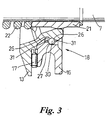
- the swash plate 13 forms part of the wobble plate arrangement 6 which comprises the swash plate 13 and a wobble plate 16 that is rotatably mounted on the swash plate 13.
- the wobble plate 16 is able to rotate freely with respect to the swash plate 13, antifriction bearings 17 and 18, as will be described in more detail below, being provided between the swash plate 13 and the wobble plate 16.
- the wobble plate 16 is also able to rotate freely with respect to the pistons 8, an additional bearing arrangement 19 being provided which allows movement of the wobble plate 16 relative to the pistons 8 in a circumferential direction by permitting the wobble plate to slide between the two halves of the bearing arrangement 19.
- the wobble plate 16 is provided with slide faces 20a and 20b.
- the swash plate 13 is not only able to swivel about the swivel point 14 but also to rotate about a guide arrangement 21 which is displaceable axially on the drive shaft 7 and loaded by a compression spring 22. Hence, as the drive shaft 7 rotates, the drive plate 10 and the articulated arm 14 connected thereto rotate and the latter drives the swash plate 13. Rotation of the swash plate 13 sets the wobble plate 16 into a wobbling motion to drive the pistons 8.
- the thrust bearing 17 comprises a roller bearing located between apposed radially extending faces 23 and 24 of the swash plate 13 and the wobble plate 16 respectively. It will be appreciated that the rollers 25 of the bearing 17 are only subjected to loads perpendicular to their axis of rotation. However, the bearing 18 is located between apposed bearing surfaces 26 and 27 provided by the swash plate 13 and the wobble plate 16 respectively and comprises a single-row grooved ball bearing which can take some thrust loads in addition to considerable radial load.
- the bearing surfaces 26 and 27 form inner and outer races and may be defined on inserts 28 and 29 that are connected respectively to the swash plate 13 and the wobble plate 16, as shown in Fig. 1.
- the rolling bearings comprise balls 30 which are located between the inner and outer bearing surfaces 26 and 27 and retained in position by a cage 31.
- the outer bearing surface 27 of the bearing 18 is provided by an appropriately profiled surface of the wobble plate 16 opposite the inner bearing surface 26.
- the outer race is thereby integrally formed with the wobble plate 16 and a separate outer insert to provide the outer race is not therefore required.
- the inner bearing surface 26 of the bearing 18 may also be provided as an integral part of the swash plate 13, obviating the requirement for the inner insert 28.
- the cage 31 holds the balls 30 in position and once inserted prevents the swash plate 13 and the wobble plate 16 from being detached from one another.
- the swash plate 13 and the wobble plate 16 are thereby integrated to form a bearing unit and may thus be manufactured as a sealed unit so that the bearing 18 cannot not be disassembled.
- At least one of one of the running surfaces of the at least one of the bearings 17, 18 and/or the rolling bearings 25 or 30 comprises a ceramic material.
- the wobble plate 16 and the swash plate 13, including any bearing insert 28, 29 attached thereto defines running surfaces for the bearings 17 and 18 which are made from hardened steel and ceramic rolling bearings 25 or 30 are used.
- the swash plate 13 is provided with a ceramic coating to form the relevant bearing surfaces of the bearings 16 and 17, the rolling bearings 25 and 30 being made conventionally of anti-friction bearing steel.
- the ceramic coatings forming the bearing surfaces of the bearings 17 and 18 are not shown in the drawings. However, it should be appreciated that they are formed by a removal of part of the surface layer of the component, such as the wobble plate 16, in the region which will define the bearing surface. A layer of ceramic material is then applied to this region, for example by thermal spraying, and mechanically finished, for example by grinding. Typically, approximately a surface layer 0.2 mm is removed from the component, which is then sprayed with a coating sufficiently thick to provide a machining allowance, for example the coating may be applied to a depth of 0.4 mm. After finishing, therefore, the ceramic coating can be ground flush with the surrounding surface of the component. Preferably, the ceramic coating has a thickness between 30 ⁇ m and 70 ⁇ m inclusive.
- Suitable ceramic materials which may be used in the invention include silicon nitride, zirconium oxide and wolfram carbide.
- a wobble plate 16 provided with ceramic bearing surfaces by the above method will not significantly add to the cost of the compressor 1, as previously steel wobble plates already required heat treatment and finishing.
- the invention also permits the wobble plate 16 to be made from aluminium provided that a strong base for the ceramic coating is provided. In this case, the thickness of the ceramic coating can be adjusted relatively freely in response to requirements.
- the use of a high-strength, heat-resistant aluminium is sufficient to satisfy the high temperature requirements of a CO 2 compressor and has a positive influence on the control characteristics of a controllable axial piston-type compressor owing to its comparatively light weight.
- dissipation of frictional heat from the bearing surfaces of the wobble plate 16 to the environment within the crank case 5 is improved.
- hybrid bearing arrangements are provided. Such hybrid arrangements have been found to be exhibit several advantages. They enable reliable running of the compressor, particularly at higher rotational speeds, as they have good tribological characteristics. The lower coefficients of thermal expansion of the ceramic material employed in comparison to that of conventional metal components and materials reduces power loss, in particular when lubricating conditions are poor and at high running temperatures, because they 'run colder' and have significantly reduced tendency to seize up. They also enable significant increases in the rotational speed of the compressor.
- the compressor 1 will operate between two limited conditions wherein the wobble plate 16 either rotates fully at the same revolutions per minute as the swash plate 13 or does not rotate and its motion is confined solely to a wobbling motion.
- the arrangement functions particularly well under high loads.
- the provision of hybrid bearing arrangements as described above advantageously enable the frictional moment of the wobble plate arrangement 6 to be optimized at low loads.
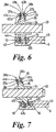
- the wobble plate arrangement 32 which is shown mounted on a drive shaft 33 via a collar 34, comprises a two-piece wobble plate 35 that is mounted on each side of a central swash plate 36.
- the swash plate 36 is fixed to the collar 34 so that it is rotated directly by the drive shaft 7. It therefore has a fixed tilt angle with respect to the shaft 7.
- the wobble plate 35 is formed in two annular pieces 37a and 37b that at least partially axially surround the swash plate 36. Between the swash plate 36 and each of the annular pieces 37a and 37b of the wobble plate 35 are bearings 38a and 38b respectively.
- bearings 38a, 38b may comprise needle or roller rolling bearings 39 which are located between apposed radially extending running surfaces formed respectively on an inner face 40a, 40b of each of the wobble plate pieces 37a, 37b and on outer faces 41a and 41b of the swash plate 36.
- the outer annular region of the swash plate 36 which is surrounded by the wobble plate 36 has a reduced thickness, as shown in Figs 6 and 7.
- the rolling bearings 39 are held in position between the wobble plate 35 and the swash plate 36 by a cage 42.
- the rolling bearings 39 may be formed in double rows.
- the wobble plate 35 may comprise two separate pieces, such as the pieces 37a, 37b in this example, or alternatively comprise two pieces that are connected to one another, either by form-fitting or force-fitting, on either side of the swash plate 36.
- the cage 42 once inserted into the arrangement 32 prevents the swash plate 36 and the wobble plate 35 from being detached from one another.
- the swash plate 36 and the wobble plate 35 are thereby integrated to form a bearing unit.
- the wobble plate 35 is fitted peripherally around the edge of the swash plate 36 and an additional radial bearing is provided between the wobble plate 35 and the swash plate 36 around the peripheral edge of the swash plate 36.
- the wobble plate 35 it is advantageous for the wobble plate 35 to comprise two separate, unconnected pieces 37a, 37b as each can then find its own separate equilibrium during use of the compressor, which can reduce frictional losses within the compressor.
- At least one of one of the running surfaces 40a, 40b, 41a, 41b of the at least one of the bearings 38a, 38b and/or the rolling bearings 39 comprises a ceramic material.
- At least the wobble plate 35 is provided with ceramic coatings to form the running surfaces 40a and 40b.
- the swash plate 36 is also provided with ceramic coatings to form the running surfaces 41a, 41b, the rolling bearings 39 being made conventionally of anti-friction bearing steel. In this way a hybrid bearing is produced which has the same advantages as detailed above.
- the wobble plate 35 and the swash plate 36 are provided with the ceramic coatings in exactly the same way as described above prior so assembly of the arrangement 32.
- the same ceramic materials may be used. Owing to the simple design of the arrangement 32, the running surfaces 40a, 40b, 41a, 41b easily accessed for coating and grinding. As a result, the axial play of the bearings 38a, 38b can be set with high precision.
- these pieces 37a, 37b can be made in the form of facing rings out of thin, light-weight material, such as aluminium, so that they exhibit only a slight inertia and produce small forces of gravity.
- the mass of such annular rings will be less than 50 g per ring and the difference between their inner and outer diameter will lie in the range 15 mm to 30 mm inclusive.
- This design also has the result that the swash plate 36 extends radially into the opening of the piston 8, between the hemispherical bearings 19.
- the outer surfaces of the wobble plate pieces 37a and 37b opposite to the running surfaces 40a, 40b comprise slide faces 43a and 43b respectively for cooperation with a bearing arrangement 19 located between the wobble plate and a piston.
- the bearings 38a, 38b will therefore also penetrate into this opening to a greater or lesser extent, dependent on the relative dimensions of the various components.
- the slide faces 43a and 43b of the wobble plate pieces 37a and 37b may also be formed by a ceramic coating.
- transverse axis 44 of the bearings 38a and 38b coincide with the longitudinal axis 45 of the piston 8 at the point in the rotation of the swash plate 36 when force is first applied to the piston 8 in the direction towards the cylinder 9, as shown in Fig. 6. It can also be advantageous to make the diameter of the sliding surface of the hemispherical bearings 19 commensurate with the operative diameter of the piston 8.
- the compressors described above typically have a housing as shown in Fig. 1 which has mounting lugs 46 integrally connected to the front housing 2 in order that the compressor can be bolted directly in position within a vehicle.
- two identical brackets 47 as shown in Figs. 8 to 10 may be used for the mounting of the compressor 1 instead.
- Each bracket 47 comprises a semicircular strap-like portion 48 in order that it can fit snugly around half of the housing 2 of the compressor and has end portions 49 that are each provided with two parallel bores 50 and 51.
- the first bore 50 which is provided with countersinking 52, is provided so that two of the brackets 47 can be positioned around the body of the compressor, typically the front housing 2, with their respective bores 50 and 52 aligned, and then bolted together so that the compressor 1 is firmly clamped between the two brackets 47.
- the second bores 51 are then used to bolt the brackets 47 and thereby the compressor 1 in position within the vehicle.
- mounting brackets 47 are to be used for mounting the compressor 1, it should be manufactured without any integral lugs 46.
- the brackets 47 are particularly suitable for a compressor 1 wherein the housing is made of forged steel, the reduction in weight of the housing 2 by virtue of the omission of the integral lugs 46 being an advantage.
Landscapes
- Engineering & Computer Science (AREA)
- General Engineering & Computer Science (AREA)
- Mechanical Engineering (AREA)
- Compressors, Vaccum Pumps And Other Relevant Systems (AREA)
Priority Applications (2)
| Application Number | Priority Date | Filing Date | Title |
|---|---|---|---|
| EP02010626A EP1363022B1 (de) | 2002-05-10 | 2002-05-10 | Taumelscheibenvorrichtung für einen Kompressor |
| DE60230239T DE60230239D1 (de) | 2002-05-10 | 2002-05-10 | Taumelscheibenvorrichtung für einen Kompressor |
Applications Claiming Priority (1)
| Application Number | Priority Date | Filing Date | Title |
|---|---|---|---|
| EP02010626A EP1363022B1 (de) | 2002-05-10 | 2002-05-10 | Taumelscheibenvorrichtung für einen Kompressor |
Publications (2)
| Publication Number | Publication Date |
|---|---|
| EP1363022A1 true EP1363022A1 (de) | 2003-11-19 |
| EP1363022B1 EP1363022B1 (de) | 2008-12-10 |
Family
ID=29265918
Family Applications (1)
| Application Number | Title | Priority Date | Filing Date |
|---|---|---|---|
| EP02010626A Expired - Lifetime EP1363022B1 (de) | 2002-05-10 | 2002-05-10 | Taumelscheibenvorrichtung für einen Kompressor |
Country Status (2)
| Country | Link |
|---|---|
| EP (1) | EP1363022B1 (de) |
| DE (1) | DE60230239D1 (de) |
Citations (7)
| Publication number | Priority date | Publication date | Assignee | Title |
|---|---|---|---|---|
| US3552886A (en) * | 1968-11-13 | 1971-01-05 | Mitchell Co John E | Compressor unit with self-contained drive means |
| JPH02301679A (ja) * | 1989-05-17 | 1990-12-13 | Toyota Autom Loom Works Ltd | 斜板式圧縮機 |
| JPH03141877A (ja) * | 1989-10-25 | 1991-06-17 | Hitachi Ltd | 斜板式圧縮機 |
| US5439297A (en) * | 1993-06-03 | 1995-08-08 | Nippon Thompson Co., Ltd. | Nonmagnetic raceway assembly |
| US5700094A (en) * | 1996-01-25 | 1997-12-23 | Caterpillar, Inc. | Bearing assembly having improved fretting and abrasion resistance |
| EP1052403A2 (de) * | 1999-05-11 | 2000-11-15 | Kabushiki Kaisha Toyoda Jidoshokki Seisakusho | Lager für einen Taumelscheibenkompressor |
| US6318899B1 (en) * | 1998-12-14 | 2001-11-20 | Ceramic Engineering Consulting, Inc. | Non-lubricated rolling element ball bearing |
-
2002
- 2002-05-10 DE DE60230239T patent/DE60230239D1/de not_active Expired - Fee Related
- 2002-05-10 EP EP02010626A patent/EP1363022B1/de not_active Expired - Lifetime
Patent Citations (7)
| Publication number | Priority date | Publication date | Assignee | Title |
|---|---|---|---|---|
| US3552886A (en) * | 1968-11-13 | 1971-01-05 | Mitchell Co John E | Compressor unit with self-contained drive means |
| JPH02301679A (ja) * | 1989-05-17 | 1990-12-13 | Toyota Autom Loom Works Ltd | 斜板式圧縮機 |
| JPH03141877A (ja) * | 1989-10-25 | 1991-06-17 | Hitachi Ltd | 斜板式圧縮機 |
| US5439297A (en) * | 1993-06-03 | 1995-08-08 | Nippon Thompson Co., Ltd. | Nonmagnetic raceway assembly |
| US5700094A (en) * | 1996-01-25 | 1997-12-23 | Caterpillar, Inc. | Bearing assembly having improved fretting and abrasion resistance |
| US6318899B1 (en) * | 1998-12-14 | 2001-11-20 | Ceramic Engineering Consulting, Inc. | Non-lubricated rolling element ball bearing |
| EP1052403A2 (de) * | 1999-05-11 | 2000-11-15 | Kabushiki Kaisha Toyoda Jidoshokki Seisakusho | Lager für einen Taumelscheibenkompressor |
Non-Patent Citations (2)
| Title |
|---|
| PATENT ABSTRACTS OF JAPAN vol. 015, no. 081 (M - 1086) 25 February 1991 (1991-02-25) * |
| PATENT ABSTRACTS OF JAPAN vol. 015, no. 358 (M - 1156) 10 September 1991 (1991-09-10) * |
Also Published As
| Publication number | Publication date |
|---|---|
| EP1363022B1 (de) | 2008-12-10 |
| DE60230239D1 (de) | 2009-01-22 |
Similar Documents
| Publication | Publication Date | Title |
|---|---|---|
| JP3918516B2 (ja) | 斜板式圧縮機 | |
| EP0410453B1 (de) | Schmiervorrichtung für eine Kolbenanordnung in einem Schiefscheibenverdichter | |
| JP3695724B2 (ja) | 斜板式コンプレッサの片頭式ピストンの製造方法 | |
| CN1273622A (zh) | 涡轮增压机的整体的轴承系统 | |
| JP2013060838A (ja) | 揺動斜板型可変容量圧縮機の揺動板の回転阻止機構およびこれを構成する等速自在継手 | |
| EP0943801B1 (de) | Taumelscheibenverdichter | |
| US4221545A (en) | Support mechanism of a wobble plate in a compressor unit | |
| EP1167761A2 (de) | Taumelscheibenverdichter | |
| EP1253318B1 (de) | Kolbenschuh für einen Taumelscheibenkompressor | |
| KR20020088348A (ko) | 사판식 압축기 | |
| EP1363022B1 (de) | Taumelscheibenvorrichtung für einen Kompressor | |
| US20090028722A1 (en) | Compressor | |
| EP0853198A2 (de) | Taumelscheibenverdichter mit verbesserter Verbindung zwischen Taumbelscheibe und Kolben | |
| EP1589241A1 (de) | Nadellager, welle, kompressor für autoklimaanlage undplanetengetriebemechanismus für automatischen gangwechsler | |
| EP1712790B1 (de) | Taumelscheibenverdichter | |
| EP1281864A1 (de) | Eine Taumelscheibenanordung für einen Verdichter | |
| US20020046646A1 (en) | Compressors | |
| EP1079110A2 (de) | Beschichtungsverfahren für eine Schrägscheibe eines Kompressors | |
| US20090151554A1 (en) | Hydrostatic displacement unit | |
| JPH03141877A (ja) | 斜板式圧縮機 | |
| EP2458212A2 (de) | Taumelscheibenkompressor und Oberflächenbehandlungsverfahren zur Behandlung einer Oberfläche einer Taumelscheibe in einem Taumelscheibenkompressor | |
| US20140196675A1 (en) | Crankdisk bearing support for the waissi internal combustion engine | |
| JP3888774B2 (ja) | 斜板式コンプレッサ用スラスト針状ころ軸受 | |
| CA1304332C (en) | Wobble plate type compressor with improved cantilever structure for the drive shaft | |
| JPH10299781A (ja) | 斜板式アキシャルプランジャーポンプ用軸受 |
Legal Events
| Date | Code | Title | Description |
|---|---|---|---|
| PUAI | Public reference made under article 153(3) epc to a published international application that has entered the european phase |
Free format text: ORIGINAL CODE: 0009012 |
|
| 17P | Request for examination filed |
Effective date: 20030328 |
|
| AK | Designated contracting states |
Kind code of ref document: A1 Designated state(s): AT BE CH CY DE DK ES FI FR GB GR IE IT LI LU MC NL PT SE TR |
|
| AX | Request for extension of the european patent |
Extension state: AL LT LV MK RO SI |
|
| AKX | Designation fees paid |
Designated state(s): DE FR GB |
|
| RAP1 | Party data changed (applicant data changed or rights of an application transferred) |
Owner name: ZEXEL VALEO COMPRESSOR EUROPE GMBH |
|
| RAP1 | Party data changed (applicant data changed or rights of an application transferred) |
Owner name: VALEO COMPRESSOR EUROPE GMBH |
|
| 17Q | First examination report despatched |
Effective date: 20061017 |
|
| GRAP | Despatch of communication of intention to grant a patent |
Free format text: ORIGINAL CODE: EPIDOSNIGR1 |
|
| GRAS | Grant fee paid |
Free format text: ORIGINAL CODE: EPIDOSNIGR3 |
|
| GRAS | Grant fee paid |
Free format text: ORIGINAL CODE: EPIDOSNIGR3 |
|
| GRAA | (expected) grant |
Free format text: ORIGINAL CODE: 0009210 |
|
| AK | Designated contracting states |
Kind code of ref document: B1 Designated state(s): DE FR GB |
|
| REG | Reference to a national code |
Ref country code: GB Ref legal event code: FG4D |
|
| REF | Corresponds to: |
Ref document number: 60230239 Country of ref document: DE Date of ref document: 20090122 Kind code of ref document: P |
|
| PLBE | No opposition filed within time limit |
Free format text: ORIGINAL CODE: 0009261 |
|
| STAA | Information on the status of an ep patent application or granted ep patent |
Free format text: STATUS: NO OPPOSITION FILED WITHIN TIME LIMIT |
|
| 26N | No opposition filed |
Effective date: 20090911 |
|
| GBPC | Gb: european patent ceased through non-payment of renewal fee |
Effective date: 20090510 |
|
| REG | Reference to a national code |
Ref country code: FR Ref legal event code: ST Effective date: 20100129 |
|
| PG25 | Lapsed in a contracting state [announced via postgrant information from national office to epo] |
Ref country code: FR Free format text: LAPSE BECAUSE OF NON-PAYMENT OF DUE FEES Effective date: 20090602 |
|
| PG25 | Lapsed in a contracting state [announced via postgrant information from national office to epo] |
Ref country code: GB Free format text: LAPSE BECAUSE OF NON-PAYMENT OF DUE FEES Effective date: 20090510 |
|
| PG25 | Lapsed in a contracting state [announced via postgrant information from national office to epo] |
Ref country code: DE Free format text: LAPSE BECAUSE OF NON-PAYMENT OF DUE FEES Effective date: 20091201 |