EP1362945A2 - Mattress label sewing clamp - Google Patents
Mattress label sewing clamp Download PDFInfo
- Publication number
- EP1362945A2 EP1362945A2 EP03252733A EP03252733A EP1362945A2 EP 1362945 A2 EP1362945 A2 EP 1362945A2 EP 03252733 A EP03252733 A EP 03252733A EP 03252733 A EP03252733 A EP 03252733A EP 1362945 A2 EP1362945 A2 EP 1362945A2
- Authority
- EP
- European Patent Office
- Prior art keywords
- movable
- movable member
- clamp
- opening
- frame
- Prior art date
- Legal status (The legal status is an assumption and is not a legal conclusion. Google has not performed a legal analysis and makes no representation as to the accuracy of the status listed.)
- Granted
Links
Images

Classifications
-
- D—TEXTILES; PAPER
- D05—SEWING; EMBROIDERING; TUFTING
- D05B—SEWING
- D05B3/00—Sewing apparatus or machines with mechanism for lateral movement of the needle or the work or both for making ornamental pattern seams, for sewing buttonholes, for reinforcing openings or for fastening articles, e.g. buttons, by sewing
- D05B3/12—Sewing apparatus or machines with mechanism for lateral movement of the needle or the work or both for making ornamental pattern seams, for sewing buttonholes, for reinforcing openings or for fastening articles, e.g. buttons, by sewing for fastening articles by sewing
- D05B3/20—Sewing apparatus or machines with mechanism for lateral movement of the needle or the work or both for making ornamental pattern seams, for sewing buttonholes, for reinforcing openings or for fastening articles, e.g. buttons, by sewing for fastening articles by sewing labels
-
- B—PERFORMING OPERATIONS; TRANSPORTING
- B25—HAND TOOLS; PORTABLE POWER-DRIVEN TOOLS; MANIPULATORS
- B25B—TOOLS OR BENCH DEVICES NOT OTHERWISE PROVIDED FOR, FOR FASTENING, CONNECTING, DISENGAGING, OR HOLDING
- B25B5/00—Clamps
- B25B5/06—Arrangements for positively actuating jaws
- B25B5/08—Arrangements for positively actuating jaws using cams
- B25B5/087—Arrangements for positively actuating jaws using cams actuated by a hydraulic or pneumatic piston
-
- D—TEXTILES; PAPER
- D05—SEWING; EMBROIDERING; TUFTING
- D05B—SEWING
- D05B35/00—Work-feeding or -handling elements not otherwise provided for
- D05B35/06—Work-feeding or -handling elements not otherwise provided for for attaching bands, ribbons, strips, or tapes or for binding
-
- D—TEXTILES; PAPER
- D05—SEWING; EMBROIDERING; TUFTING
- D05C—EMBROIDERING; TUFTING
- D05C9/00—Appliances for holding or feeding the base fabric in embroidering machines
- D05C9/02—Appliances for holding or feeding the base fabric in embroidering machines in machines with vertical needles
- D05C9/04—Work holders, e.g. frames
-
- D—TEXTILES; PAPER
- D05—SEWING; EMBROIDERING; TUFTING
- D05B—SEWING
- D05B11/00—Machines for sewing quilts or mattresses
Definitions
- This invention relates generally to sewing machines and more particularly, to a method and apparatus for holding a mattress label while it is being sewn to a mattress panel.
- identifying labels are preferably made of a high quality material and attached to the product in a high quality manner.
- mattress companies have specifications regarding the appearance and the attachment of the label. Among these is the requirement that the outer edge of the label must be securely sewn to a top panel of the mattress.
- the label should not have trim tails or other unsightly features.
- the invention provides a clamping system for a sewing machine.
- the sewing machine has a frame and an opening in the frame for receiving a first material that is to be sewn with the sewing machine to a second material.
- the clamping system has a plurality of clamps mounted adjacent the opening in the frame.
- Each of the clamps has a stationary member, a movable member and an actuator.
- the actuator is connected to the movable member and operates to move the movable member in a clamping relationship with the stationary member to clamp the first material in the clamp.
- the clamp is powered by a cylinder with a linear stroke and the clamp has a driving member that transfers the linear motion of the cylinder into a pivoting motion of the movable member.
- the movable and fixed members have forward ends shaped so that they hold the first material but do not interfere with a sewing of the first material to the second material.
- a method of securing a stitchable material in a sewing machine having a frame and an opening in the frame for receiving the stitchable material.
- an edge of the stitchable material is located between a movable member and a fixed member of a clamp mounted adjacent the opening.
- the movable member is moved toward the stationary member to clamp the edge of the stitchable material between the movable and the stationary members.
- a driving member is translated by an actuator and raises a rearward end of the movable member, thereby pivoting a forward end of the movable member against a forward end of the stationary member.
- the preferred clamping system reliably secures the mattress label while it is being sewn on a mattress panel.
- the clamping system is easier to use and therefore, leads to a faster and ore reliable placement of the mattress label in the sewing machine.
- the clamping system is especially useful in a production environment where its ease of use and reliability help to substantially relieve sewing machine operator stress in the process of sewing a label to a product. Further, the clamping system substantially reduces rework or resewing of a label and therefore, provides a more efficient cost effective label sewing operation.
- a sewing system 20 includes a frame 22 mounted on a base plate 24.
- the base plate 24 and a pivotable panel clamp 28 are movable in mutually perpendicular X and Y directions with respect to a base 27 in a known manner.
- a sewing machine 30 has a needle 34, a presser foot 36, a bobbin (not shown) and actuators (not shown) for moving the base plate 24 and panel clamp 28 in response to command signals from a sewing machine controller 38 in a known manner.
- the sewing machine 30 is an electronically programmable X-Y sewing machine that, in one embodiment, utilizes a Mitsubishi No. PLK A 4516 sewing machine.
- the sewing machine 30 performs lock-stitching and may be programmed to implement different styles of lock-stitching, for example, a zig-zag stitch of 7.5 millimeters.
- Lock-stitching is a known technique of interlacing a needle thread and bobbin thread, which will not be described here further except to indicate that a needle thread is carried by needle 34 and a bobbin thread provided by a bobbin (not shown).
- the operation of the sewing machine 30 is controlled by user operating I/O devices 37 on a front panel of the controller 38.
- the controller 38 receives inputs from devices, for example, a main shaft encoder, and provides command signals to a sewing head motor (not shown) and actuators (not shown) to implement a stitch pattern in a known manner.
- the controller 38 also provides command signals to perform other operations, for example, raise and lower the presser foot 36, raise and lower the panel clamp 28, etc.
- the command signals are received by solenoids (not shown) that, in turn, change the states of pneumatic logic, which supply pressurized air to various pneumatic components in a known manner.
- the sewing machine 30 is illustrated with the panel clamp 28 in its raised position.
- the label frame 22 and base plate 24 have respective openings 40 in which a mattress label 42 can be located.
- a label clamping system 44 is used to hold the mattress label 42 within the opening 40.
- the label clamping system 44 is comprised of four clamps 46 mounted on the label frame 22. Each of the clamps is identical in its structure and operation.
- a clamp 46 has an actuator 50, for example, a pneumatic cylinder, mounted to an upper side of the frame 22 by fasteners 48 or other means.
- the actuator 50 has an actuator shaft or rod 52, for example, a cylinder rod, extending from a forward end.
- the actuator rod 52 extends and retracts or translates through a linear motion in response to the actuator 50 being operated between its two states.
- the actuator rod 52 is connected to a rearward end of a toggle driver 54 by a pin or other fastener 56.
- the toggle driver 54 has a slot 58 that receives a guide pin 60, for example, a screw or other fastener.
- the slot 58 and guide pin 60 function with the actuator rod 52 to facilitate a translation or linear motion of the toggle driver 54.
- a movable pivot clip or member 64 is pivotally mounted on the frame 22 with a pivot pin 66 that is located in a groove 68 and secured by pin clamps 70. As shown in Fig. 3, the pivot clip 64 is mounted in a slot 72 located in an upper surface of the frame 22.
- a fixed or stationary clip 74 is mounted by fasteners (not shown) in a slot 76 located in a lower surface of the label frame 22.
- the forward end 78 of the movable clip 64 and the forward end 80 of the fixed clip 74 extend over an opening edge 81 and into the opening 40 in the label frame 22.
- the forward ends 78, 80 of the respective clips 64, 74 have a shape that is effective to secure the label 42 therebetween but does not interfere with the sewing machine sewing around a perimeter of the label 42.
- the forward ends 78, 80 of each of the respective clips 64, 74 terminate with a pair of small pointed tips 82 that are separated by a V-shaped cutout 84.
- the forward end of the toggle driver 54 has an angled or inclined surface 62 that receives a rearward end 86 of the pivot clip 64.
- the actuator 50 When the actuator 50 is in a first state in which the actuator rod 52 is fully retracted, the rearward end 86 of the pivot clip 64 is located at a lower end of the inclined surface 62, thereby placing the forward end 78 of the pivot clip 64 in a raised position.
- a user generated command signal from the controller 38 changes a state of an actuator solenoid (not shown) that, in turn, changes a flow of pressurized air to the actuator 50, thereby changing its state. Changing the state of the actuator 50 extends the actuator rod 52 and moves the toggle driver 54 forward, that is, from left to right as viewed in Fig. 3.
- a user operates appropriate I/O devices 37 on the controller 38 to move the base plate 24 to a desired starting location and then to raise panel clamp 28 in a known manner. Thereafter, the user disposes a label 42 face-side down in the opening 40 and locates edges of the label 42 on the forward ends 80 (Fig. 3) of respective stationary clips 74. When the label edges are located on the stationary clips 74 to the user's satisfaction, the user operates appropriate I/O devices 37 on the controller 38 to command a change of state of all of the actuators 50 (Fig. 3) of all respective clamps 46. The actuators 50 simultaneously extend respective actuator rods 52 and move respective toggle drivers 54 forward.
- the user then places a mattress panel (not shown) over the clamped label 42.
- the user again activates appropriate I/O devices 37 on the controller 38 to lower the panel clamp 28.
- the panel clamp 28 secures the mattress panel against the frame 22 in a desired position relative to the clamped label 42 in a known manner.
- the user then operates the sewing machine 30 so that the label is sewn to the mattress panel with a lock-stitch along an edge of the label.
- the pointed profiles of the forward ends 78, 80 of the respective pivot and stationary clips 64, 74 permit the label edge to be satisfactorily secured and also allow a zig-zag stitch or the like to proceed down a label edge without interference from the clamps 46.
- the user again operates appropriate I/O devices 37 on the controller 38 to raise the panel clamp 28.
- the user operates appropriate I/O devices 37 to command a change of state of all of the actuators 50 (Fig. 3) of the respective clamps 46.
- the actuators 50 simultaneously retract respective actuator rods 52 and move respective toggle drivers 54 rearward.
- the mattress panel is resting on top of the forward ends 78 of the pivot clips 64; and therefore, the rearward ends 86 remain elevated after the respective toggle drivers 54 have been retracted.
- the user then lifts the mattress panel and sewn label off of the sewing apparatus 20.
- the mattress label 42 is between the pivot clips 64 and respective stationary clips 74; and as the mattress label 42 is raised from the frame 22, it raises the forward ends 78 of respective pivot clips 64.
- the rearward ends 86 of the respective pivot clips 64 drop down onto lower ends of respective inclined surfaces 62, and all of the clamps 46 are open ready to receive another mattress label.
- the above-described clamping system 44 reliably secures a label while it is being sewn to a mattress panel.
- the clamping system 44 is easy to use and therefore, leads to a faster and more reliable placement of the mattress label in the label frame 22 of the sewing machine 30.
- the clamping system 44 is especially useful in a production environment where its ease of use and reliability help to substantially relieve sewing machine operator stress in the process of sewing a label 42 to a product. Further, the clamping system 44 substantially reduces rework or resewing of a label and therefore, provides a more efficient and cost effective label sewing operation.
- clamps 46 are mounted as two opposed pairs of clamps on opposite lateral sides of the frame 22.
- the clamps 46 may be arranged in other configurations around the perimeter of the frame 22, for example, one clamp can be mounted on each of the four sides of the frame 22 or the two pairs of clamps may be mounted on opposed upper and lower sides of the frame 22.
- the sewing system 20 is used to sew a label onto a mattress panel; however, as will be appreciated, the sewing system 20 can be used to sew other stitchable materials, for example, leather, a "KEVLAR" composite material, etc. Therefore, in other embodiments, the number of clamps 46 used can be changed to meet the needs of a particular application, for example, depending on the stiffness of the materials being sewn, a greater number or a fewer number of clamps 46 may be used. Further, in the described embodiment, the clamp actuator 50 is described as being pneumatically operated; however as will be appreciated, in other embodiments, the clamp actuator 50 may be electrically operated.
- the pivot clip 64 is opened by the act of the sewn mattress panel and label being removed from the sewing system 20.
- a positive opening force can also be applied to the pivot member 64, for example, a torsion spring can be mounted over the pivot pin 66 and used to apply a biasing force to help move the pivot clip rearward end 86 down the inclined surface 62.
- the toggle driver 54 can be replaced by other mechanisms for operatively connecting the actuator 46 to the pivot clip 64.
Landscapes
- Engineering & Computer Science (AREA)
- Textile Engineering (AREA)
- Mechanical Engineering (AREA)
- Sewing Machines And Sewing (AREA)
Abstract
Description
- This invention relates generally to sewing machines and more particularly, to a method and apparatus for holding a mattress label while it is being sewn to a mattress panel.
- Manufacturers are particularly concerned that high quality products portray a high quality image. To this end, identifying labels are preferably made of a high quality material and attached to the product in a high quality manner. In the mattress field, mattress companies have specifications regarding the appearance and the attachment of the label. Among these is the requirement that the outer edge of the label must be securely sewn to a top panel of the mattress. In addition, the label should not have trim tails or other unsightly features.
- Label sewing machines are known. One such machine is disclosed in U.S. Patent No. 5,520,129 entitled "Method and Apparatus for Join and Sew Application". With such a machine a mattress label is placed in a frame and held therein by pins or tacks located at each comer of the frame. While the tacks function well to hold the label, it requires mental focus and manual dexterity to manipulate each small corner of the label such that it is properly secured to a respective tack. When performed repeatedly over periods of time, such an operation can be stressful and prone to error. In addition, a comer of the label may accidently come off of its respective tack. Whether from an improper loading of the label or an accidental release of a label comer, a loose label comer often results in the label not being properly sewn on the mattress. Manually removing and/or resewing the label on the mattress panel is labor intensive and expensive.
- Therefore, there is a need for a better way to more reliably secure the mattress label while it is being sewn on a mattress panel.
- According to the pnnciples of the present invention and in accordance with the described embodiments, the invention provides a clamping system for a sewing machine. The sewing machine has a frame and an opening in the frame for receiving a first material that is to be sewn with the sewing machine to a second material. The clamping system has a plurality of clamps mounted adjacent the opening in the frame. Each of the clamps has a stationary member, a movable member and an actuator. The actuator is connected to the movable member and operates to move the movable member in a clamping relationship with the stationary member to clamp the first material in the clamp.
- In preferred embodiments, the clamp is powered by a cylinder with a linear stroke and the clamp has a driving member that transfers the linear motion of the cylinder into a pivoting motion of the movable member. Further, the movable and fixed members have forward ends shaped so that they hold the first material but do not interfere with a sewing of the first material to the second material.
- In another aspect of the invention there is provided a method of securing a stitchable material in a sewing machine having a frame and an opening in the frame for receiving the stitchable material. First, an edge of the stitchable material is located between a movable member and a fixed member of a clamp mounted adjacent the opening. Next, the movable member is moved toward the stationary member to clamp the edge of the stitchable material between the movable and the stationary members. In one embodiment, a driving member is translated by an actuator and raises a rearward end of the movable member, thereby pivoting a forward end of the movable member against a forward end of the stationary member.
- The preferred clamping system reliably secures the mattress label while it is being sewn on a mattress panel. The clamping system is easier to use and therefore, leads to a faster and ore reliable placement of the mattress label in the sewing machine. Thus, the clamping system is especially useful in a production environment where its ease of use and reliability help to substantially relieve sewing machine operator stress in the process of sewing a label to a product. Further, the clamping system substantially reduces rework or resewing of a label and therefore, provides a more efficient cost effective label sewing operation.
- The invention will now be described by way of example with reference to the accompanying drawings in which:
- Fig. I is a schematic perspective view of a mattress label sewing system utilizing a clamping system in accordance with the principles of the present invention.
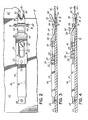
- Fig. 2 is top plan view of one of the clamps of the clamping system illustrated in Fig. 1.
- Fig. 3 is side view in partial cross-section of the clamp of Fig. 2 illustrating the clamp in an open position.
- Fig. 4 is side view in partial cross-section of the clamp of Fig. 2 illustrating the clamp in a closed position.
-
- Referring to Fig. I, a
sewing system 20 includes aframe 22 mounted on abase plate 24. Thebase plate 24 and apivotable panel clamp 28 are movable in mutually perpendicular X and Y directions with respect to abase 27 in a known manner. Asewing machine 30 has aneedle 34, apresser foot 36, a bobbin (not shown) and actuators (not shown) for moving thebase plate 24 andpanel clamp 28 in response to command signals from asewing machine controller 38 in a known manner. - The
sewing machine 30 is an electronically programmable X-Y sewing machine that, in one embodiment, utilizes a Mitsubishi No. PLK A 4516 sewing machine. Thesewing machine 30 performs lock-stitching and may be programmed to implement different styles of lock-stitching, for example, a zig-zag stitch of 7.5 millimeters. Lock-stitching is a known technique of interlacing a needle thread and bobbin thread, which will not be described here further except to indicate that a needle thread is carried byneedle 34 and a bobbin thread provided by a bobbin (not shown). - The operation of the
sewing machine 30 is controlled by user operating I/O devices 37 on a front panel of thecontroller 38. During execution of a control program, thecontroller 38 receives inputs from devices, for example, a main shaft encoder, and provides command signals to a sewing head motor (not shown) and actuators (not shown) to implement a stitch pattern in a known manner. Thecontroller 38 also provides command signals to perform other operations, for example, raise and lower thepresser foot 36, raise and lower thepanel clamp 28, etc. In those operations, the command signals are received by solenoids (not shown) that, in turn, change the states of pneumatic logic, which supply pressurized air to various pneumatic components in a known manner. The air cylinders and other pneumatic devices are commercially available from various suppliers, for example, Bimba Manufacturing Company of Monee, Illinois. The structure and operation of a sewing machine similar to the sewing machine described herein is fully described in U.S. Patent No. 5,520,129 entitled "Method and Apparatus for Join and Sew Application." - The
sewing machine 30 is illustrated with thepanel clamp 28 in its raised position. Thelabel frame 22 andbase plate 24 haverespective openings 40 in which amattress label 42 can be located. Alabel clamping system 44 is used to hold themattress label 42 within the opening 40. Thelabel clamping system 44 is comprised of fourclamps 46 mounted on thelabel frame 22. Each of the clamps is identical in its structure and operation. - Referring to Fig. 2, a
clamp 46 has anactuator 50, for example, a pneumatic cylinder, mounted to an upper side of theframe 22 byfasteners 48 or other means. Theactuator 50 has an actuator shaft orrod 52, for example, a cylinder rod, extending from a forward end. Theactuator rod 52 extends and retracts or translates through a linear motion in response to theactuator 50 being operated between its two states. Theactuator rod 52 is connected to a rearward end of atoggle driver 54 by a pin orother fastener 56. Thetoggle driver 54 has aslot 58 that receives aguide pin 60, for example, a screw or other fastener. Theslot 58 and guidepin 60 function with theactuator rod 52 to facilitate a translation or linear motion of thetoggle driver 54. - A movable pivot clip or
member 64 is pivotally mounted on theframe 22 with apivot pin 66 that is located in agroove 68 and secured bypin clamps 70. As shown in Fig. 3, thepivot clip 64 is mounted in aslot 72 located in an upper surface of theframe 22. A fixed orstationary clip 74 is mounted by fasteners (not shown) in aslot 76 located in a lower surface of thelabel frame 22. Theforward end 78 of themovable clip 64 and theforward end 80 of the fixedclip 74 extend over anopening edge 81 and into the opening 40 in thelabel frame 22. The forward ends 78, 80 of therespective clips label 42 therebetween but does not interfere with the sewing machine sewing around a perimeter of thelabel 42. As shown in Fig. 2, the forward ends 78, 80 of each of therespective clips pointed tips 82 that are separated by a V-shapedcutout 84. - Referring to Fig. 3, the forward end of the
toggle driver 54 has an angled orinclined surface 62 that receives arearward end 86 of thepivot clip 64. When theactuator 50 is in a first state in which theactuator rod 52 is fully retracted, therearward end 86 of thepivot clip 64 is located at a lower end of theinclined surface 62, thereby placing theforward end 78 of thepivot clip 64 in a raised position. A user generated command signal from thecontroller 38 changes a state of an actuator solenoid (not shown) that, in turn, changes a flow of pressurized air to theactuator 50, thereby changing its state. Changing the state of theactuator 50 extends theactuator rod 52 and moves thetoggle driver 54 forward, that is, from left to right as viewed in Fig. 3. As theinclined surface 62 is moved forward, therearward end 86 of thepivot clip 64 moves up theinclined surface 62, thereby pivoting thepivot clip 64 clockwise as viewed in Fig. 3 about thepivot pin 66. Raising therearward end 86 of thepivot clip 64 simultaneously lowers itsforward end 78. Referring to Fig. 4, when theactuator rod 52 is fully extended, the pivot clip forward end 78 is closed against theforward end 80 of thestationary clip 74, thereby closing theclamp 46 and securing thelabel 42 therein. - When the command signal from the
controller 38 again changes state, it changes the state of the actuator solenoid that, in turn, changes a flow of pressurized air to return theactuator 50 to its original state. In that process,actuator rod 52 is retracted; and thetoggle driver 54 moves rearward, that is, from right to left as viewed in Fig. 4. As will subsequently be described, thepivot clip 64 is pivoted counterclockwise as viewed in Fig. 3 and itsrearward end 86 moves down theinclined surface 62. The lowering of therearward end 86 of thepivot clip 64 simultaneously raises itsforward end 78, thereby opening theclamp 46 as shown in Fig. 3. The pivot clip rearward end 86 is made to be heavier than theforward end 78, and therefore, the pivot clip rearward end 86 tends to drop down. - In use, referring to Fig. 1, a user operates appropriate I/
O devices 37 on thecontroller 38 to move thebase plate 24 to a desired starting location and then to raisepanel clamp 28 in a known manner. Thereafter, the user disposes alabel 42 face-side down in theopening 40 and locates edges of thelabel 42 on the forward ends 80 (Fig. 3) of respective stationary clips 74. When the label edges are located on thestationary clips 74 to the user's satisfaction, the user operates appropriate I/O devices 37 on thecontroller 38 to command a change of state of all of the actuators 50 (Fig. 3) of allrespective clamps 46. Theactuators 50 simultaneously extendrespective actuator rods 52 and moverespective toggle drivers 54 forward. The forward motion of therespective toggle drivers 54 lowers respective pivot clip forward ends 78 against respective stationary clip forward ends 80. That process simultaneously closes all of theclamps 46 and clamps edges of thelabel 42 between the pivot clip forward ends 78 and respective stationary clip forward ends 80. As will be appreciated, after theclamps 46 have been closed, the user can operate appropriate I/O devices 37 on thecontroller 38 to command theclamps 46 to open, so that edges of thelabel 42 can be repositioned. Theclamps 46 are then closed again as described above. - After the
label 42 is properly positioned within theopening 40, the user then places a mattress panel (not shown) over the clampedlabel 42. The user again activates appropriate I/O devices 37 on thecontroller 38 to lower thepanel clamp 28. Thepanel clamp 28 secures the mattress panel against theframe 22 in a desired position relative to the clampedlabel 42 in a known manner. The user then operates thesewing machine 30 so that the label is sewn to the mattress panel with a lock-stitch along an edge of the label. The pointed profiles of the forward ends 78, 80 of the respective pivot andstationary clips clamps 46. - After the sewing operation is complete, the user again operates appropriate I/
O devices 37 on thecontroller 38 to raise thepanel clamp 28. Next, the user operates appropriate I/O devices 37 to command a change of state of all of the actuators 50 (Fig. 3) of therespective clamps 46. Theactuators 50 simultaneously retractrespective actuator rods 52 and moverespective toggle drivers 54 rearward. However, after the sewing operation, the mattress panel is resting on top of the forward ends 78 of the pivot clips 64; and therefore, the rearward ends 86 remain elevated after therespective toggle drivers 54 have been retracted. The user then lifts the mattress panel and sewn label off of thesewing apparatus 20. Themattress label 42 is between the pivot clips 64 and respectivestationary clips 74; and as themattress label 42 is raised from theframe 22, it raises the forward ends 78 of respective pivot clips 64. Thus, the rearward ends 86 of the respective pivot clips 64 drop down onto lower ends of respectiveinclined surfaces 62, and all of theclamps 46 are open ready to receive another mattress label. - The above-described
clamping system 44 reliably secures a label while it is being sewn to a mattress panel. Theclamping system 44 is easy to use and therefore, leads to a faster and more reliable placement of the mattress label in thelabel frame 22 of thesewing machine 30. Thus, theclamping system 44 is especially useful in a production environment where its ease of use and reliability help to substantially relieve sewing machine operator stress in the process of sewing alabel 42 to a product. Further, theclamping system 44 substantially reduces rework or resewing of a label and therefore, provides a more efficient and cost effective label sewing operation. - While the present invention has been illustrated by a description of an embodiment and while that embodiment has been described in considerable detail, additional advantages and modifications will readily appear to those skilled in the art. For example, in the described embodiment of Fig. 2, four
clamps 46 are mounted as two opposed pairs of clamps on opposite lateral sides of theframe 22. As will be appreciated, in other embodiments, theclamps 46 may be arranged in other configurations around the perimeter of theframe 22, for example, one clamp can be mounted on each of the four sides of theframe 22 or the two pairs of clamps may be mounted on opposed upper and lower sides of theframe 22. - In the described embodiment, the
sewing system 20 is used to sew a label onto a mattress panel; however, as will be appreciated, thesewing system 20 can be used to sew other stitchable materials, for example, leather, a "KEVLAR" composite material, etc. Therefore, in other embodiments, the number ofclamps 46 used can be changed to meet the needs of a particular application, for example, depending on the stiffness of the materials being sewn, a greater number or a fewer number ofclamps 46 may be used. Further, in the described embodiment, theclamp actuator 50 is described as being pneumatically operated; however as will be appreciated, in other embodiments, theclamp actuator 50 may be electrically operated. - In the described embodiment, the
pivot clip 64 is opened by the act of the sewn mattress panel and label being removed from thesewing system 20. However, as will be appreciated, in alternative embodiments, a positive opening force can also be applied to thepivot member 64, for example, a torsion spring can be mounted over thepivot pin 66 and used to apply a biasing force to help move the pivot clip rearward end 86 down theinclined surface 62. In still other embodiments thetoggle driver 54 can be replaced by other mechanisms for operatively connecting theactuator 46 to thepivot clip 64.
Claims (21)
- A clamping system for a sewing machine having a frame and an opening in the frame for receiving a first material to be sewn with the sewing machine to a second material, the clamping system comprising:a plurality of clamps mounted adjacent the opening in the frame, each of the clamps comprisinga stationary member,a movable member, andan actuator connected to the movable member and operable to move the movable member in a clamping relationship with the stationary member and adapted to clamp the first material in the clamp.
- The clamping system of claim I further comprising a driving member connected between the actuator and the movable member for transferring actuator motion to the movable member.
- The clamping system of claim 2 wherein the driving member pivots the movable member in response to a linear motion of the actuator
- The clamping system of claim 3 wherein the stationary member has a forward end extending over an edge of the opening and into the opening.
- The clamping system of either claim 3 or claim 4 wherein the movable member is pivotally mounted on the frame and has a rearward end and a forward end, the forward end of the movable member extends over an edge of the opening and into the opening.
- The clamping system of claim 5 wherein the actuator has an actuator rod and the driving member has a rearward end connected to the actuator rod and an inclined forward end receiving the rearward end of the movable chamber.
- The clamping system of claim 6 wherein the actuator rod is extendable and moves the driving member forward to pivot the movable member clockwise toward the stationary member to close the clamp.
- The clamping system of claim 7 wherein the actuator rod is retractable and moves the driving member rearward to pivot the movable member counterclockwise away from the stationary member to open the clamp.
- The clamping system of claim 4 or any one of claims 5 to 8 as dependent on claim 4 wherein the forward ends of the movable and the stationary members comprise respective shapes extending into the opening and not interfering with a stitch sewn by the sewing machine around a perimeter of the first material.
- The clamping system of claim 9 wherein the forward ends of the movable and the stationary members further comprise substantially identical shapes extending into the opening.
- The clamping system of claim 10 wherein each of the forward ends of the movable and the stationary members further comprise a substantially pointed tip extending into the opening.
- The clamping system of claim 10 wherein each of the forward ends of the movable and the stationary members further comprise a pair of substantially pointed tips separated by a V-shaped cutout extending into the opening.
- A sewing machine for sewing first and second materials together comprising a base, a base plate movably mounted with respect to the base and having a base plate opening therethrough, a frame having a frame opening adapted to receive the first material therein, a clamping system as claimed in any preceding claim, a stationary member, a movable member, the movable and stationary members adapted to clamp the first material in the frame opening, a panel clamp movably mounted with respect to the base and adapted to clamp the second material over the first material, a sewing machine for sewing the first and the second materials together, and a controller for controlling an operation of the sewing machine.
- A method of securing a first, stitchable, material in a sewing machine having a frame and an opening in the frame for receiving the stitchable material, the method comprising
- The method of claim 14 further comprising transferring a linear motion of an actuator into a pivoting motion of the movable member.
- The method of claim 15 further comprising raising a rearward end of the movable member and simultaneously lowering a forward end of the movable member toward a forward end of the stationary member to clamp the stitchable material between the forward ends of the movable and stationary members.
- The method of claim 14 further comprising:translating a driving member forward with the actuator; andraising the rearward end of the movable member with an angled surface of a forward end of the driving member to simultaneously lower the forward end of the movable member and close the clamp on the stitchable material.
- The method of claim 17 further comprising lowering a rearward end of the movable member and simultaneously raising a forward end of the movable member away from a forward end of the stationary member to release the stitchable material between the forward ends of the movable and stationary members.
- The method of claim 18 further comprising:translating a driving member rearward with the actuator; andlowering the rearward end of the movable member with the angled surface of a forward end of the driving member to simultaneously raise the forward end of the movable member.
- A method of sewing a first material to a second material in a sewing machine having a frame and an opening in the frame for receiving the first material, the method comprising securing the first material as claimed in any one of claims 14 to 19, locating the second material over the first material to orient the first material at a desired position with respect to the second material, securing the second material against the frame with a panel clamp, and sewing the first and second materials together.
- The method of claim 20 further comprising:releasing the second material from the frame by releasing the panel clamp; andmoving the movable member away from the stationary member to unclamp the edge of the first material from between the movable and the stationary members.
Applications Claiming Priority (2)
| Application Number | Priority Date | Filing Date | Title |
|---|---|---|---|
| US147638 | 2002-05-17 | ||
| US10/147,638 US6662737B2 (en) | 2002-05-17 | 2002-05-17 | Mattress label sewing clamp |
Publications (3)
| Publication Number | Publication Date |
|---|---|
| EP1362945A2 true EP1362945A2 (en) | 2003-11-19 |
| EP1362945A3 EP1362945A3 (en) | 2005-02-09 |
| EP1362945B1 EP1362945B1 (en) | 2017-12-27 |
Family
ID=29269769
Family Applications (1)
| Application Number | Title | Priority Date | Filing Date |
|---|---|---|---|
| EP03252733.5A Expired - Lifetime EP1362945B1 (en) | 2002-05-17 | 2003-04-30 | Mattress label sewing clamp |
Country Status (2)
| Country | Link |
|---|---|
| US (1) | US6662737B2 (en) |
| EP (1) | EP1362945B1 (en) |
Cited By (3)
| Publication number | Priority date | Publication date | Assignee | Title |
|---|---|---|---|---|
| CN101173431B (en) * | 2006-11-03 | 2011-06-08 | 日星特殊精密株式会社 | Rack and pinion type power transmission and apparatus for driving embroidery frame of embroidery machine having the same |
| CN106319789A (en) * | 2016-06-28 | 2017-01-11 | 诸暨创加电子设备有限公司 | Embroiderer, tool and assembling method |
| CN106319792A (en) * | 2016-06-23 | 2017-01-11 | 诸暨创加电子设备有限公司 | Hand-piece positioning mechanism and mounting method thereof |
Families Citing this family (5)
| Publication number | Priority date | Publication date | Assignee | Title |
|---|---|---|---|---|
| US7100526B1 (en) | 2004-09-27 | 2006-09-05 | Atlanta Attachment Company, Inc. | Label/tag inserter system |
| US8739716B2 (en) * | 2010-02-23 | 2014-06-03 | Atlanta Attachment Company | Automated quilting and tufting system |
| CN104233648B (en) * | 2014-09-17 | 2017-02-22 | 东莞市迈特运动用品有限公司 | Woven glove label stitching jig and woven glove label stitching method |
| CN106120182A (en) * | 2016-08-22 | 2016-11-16 | 际华三五三实业有限公司 | A kind of mould sewing up trade mark and method |
| CN110877196B (en) * | 2019-12-08 | 2021-08-06 | 湖南凯斯机械股份有限公司 | Processing technology for improving processing efficiency of sewing machine head |
Citations (3)
| Publication number | Priority date | Publication date | Assignee | Title |
|---|---|---|---|---|
| US3482536A (en) | 1967-08-22 | 1969-12-09 | Mas Fab Carl Zangs | Fast tenter frame for multi-head embroidering machines |
| US5520129A (en) | 1994-03-17 | 1996-05-28 | Porter Sewing Machines, Inc. | Method and apparatus for join and sew application |
| US5595375A (en) | 1995-05-12 | 1997-01-21 | Benn Corporation | Self-tightening, easily releasable clamping device capable of being retained in an open position |
Family Cites Families (7)
| Publication number | Priority date | Publication date | Assignee | Title |
|---|---|---|---|---|
| US3044426A (en) * | 1960-03-23 | 1962-07-17 | Schwarzberger Arthur | Work-handling apparatus for quilting machines |
| CH429397A (en) * | 1965-01-25 | 1967-01-31 | Luxar S A R L | Method for lining a frame by means of a stretched canvas and device for carrying out this method |
| US3724836A (en) | 1971-07-12 | 1973-04-03 | Dover Corp | Power operated swing clamp |
| IT1159279B (en) | 1982-05-17 | 1987-02-25 | Necchi Spa | AUTOMATIC EQUIPMENT FOR SEWING PERFORMANCE ACCORDING TO A DETERMINED PROFILE |
| ATE153913T1 (en) * | 1993-10-27 | 1997-06-15 | Sefar Ag | DEVICE FOR CLAMPING A PIECE OF TISSUE |
| US6065412A (en) | 1997-02-25 | 2000-05-23 | Schwarzberger; Michael V. | Vertical stitching machine and method |
| US6123042A (en) * | 1999-04-09 | 2000-09-26 | Durkopp Adler Aktiengesellschaft | Automatic sewing machine |
-
2002
- 2002-05-17 US US10/147,638 patent/US6662737B2/en not_active Expired - Lifetime
-
2003
- 2003-04-30 EP EP03252733.5A patent/EP1362945B1/en not_active Expired - Lifetime
Patent Citations (3)
| Publication number | Priority date | Publication date | Assignee | Title |
|---|---|---|---|---|
| US3482536A (en) | 1967-08-22 | 1969-12-09 | Mas Fab Carl Zangs | Fast tenter frame for multi-head embroidering machines |
| US5520129A (en) | 1994-03-17 | 1996-05-28 | Porter Sewing Machines, Inc. | Method and apparatus for join and sew application |
| US5595375A (en) | 1995-05-12 | 1997-01-21 | Benn Corporation | Self-tightening, easily releasable clamping device capable of being retained in an open position |
Cited By (4)
| Publication number | Priority date | Publication date | Assignee | Title |
|---|---|---|---|---|
| CN101173431B (en) * | 2006-11-03 | 2011-06-08 | 日星特殊精密株式会社 | Rack and pinion type power transmission and apparatus for driving embroidery frame of embroidery machine having the same |
| CN106319792A (en) * | 2016-06-23 | 2017-01-11 | 诸暨创加电子设备有限公司 | Hand-piece positioning mechanism and mounting method thereof |
| CN106319792B (en) * | 2016-06-23 | 2019-12-17 | 诸暨创加电子设备有限公司 | Machine head positioning mechanism and mounting method |
| CN106319789A (en) * | 2016-06-28 | 2017-01-11 | 诸暨创加电子设备有限公司 | Embroiderer, tool and assembling method |
Also Published As
| Publication number | Publication date |
|---|---|
| US6662737B2 (en) | 2003-12-16 |
| EP1362945B1 (en) | 2017-12-27 |
| EP1362945A3 (en) | 2005-02-09 |
| US20030213418A1 (en) | 2003-11-20 |
Similar Documents
| Publication | Publication Date | Title |
|---|---|---|
| US5927221A (en) | Method and apparatus for join and sew application | |
| US5588384A (en) | Method and apparatus of folding opposite ends of a piece of tape | |
| CN107304496A (en) | Sewing machine | |
| US4854251A (en) | Automatic sewing machine exclusively used for sewing zipper on workpiece | |
| US6662737B2 (en) | Mattress label sewing clamp | |
| US5553564A (en) | Automatic sewing machine system and method for loading and sewing workpieces | |
| CN1861873B (en) | buttonhole sewing machine | |
| US4870917A (en) | Work holder for sewing machines | |
| CN106245239B (en) | Clamping mechanism and sewing machine with same | |
| US5094179A (en) | Attachable label sewing apparatus | |
| US5109785A (en) | Workpiece fabric feeding device for binder strip sewing machine | |
| JP4409049B2 (en) | Cloth opening device for hole sewing machine | |
| US4589359A (en) | Workpiece receiving device for a sewing machine, in particular for a computer-controlled automatic sewing device | |
| US4648335A (en) | Apparatus for setting a workpiece correctly on a sewing machine | |
| US4892049A (en) | Automatic sewing machine exclusively used for sewing zipper on workpiece | |
| US20030192463A1 (en) | Buttonhole sewing machine | |
| US4898109A (en) | Device for sewing a collar on to a body of an article of clothing | |
| KR101162366B1 (en) | Eye-type buttonhole sewing machine | |
| JPH10314473A (en) | Automatic sewing device for sewing flap to object to be worked | |
| US5609115A (en) | Buttonhole closing device for lockstitch bar tacking sewing machine | |
| CN105506867A (en) | Sewing machine | |
| JPH0358756B2 (en) | ||
| US5598801A (en) | Easy loading sewing station | |
| JP2520868B2 (en) | Automatic sewing machine for zippers | |
| JPH06134153A (en) | Automatic sewing machine for colar lining cloth padding |
Legal Events
| Date | Code | Title | Description |
|---|---|---|---|
| PUAI | Public reference made under article 153(3) epc to a published international application that has entered the european phase |
Free format text: ORIGINAL CODE: 0009012 |
|
| AK | Designated contracting states |
Kind code of ref document: A2 Designated state(s): AT BE BG CH CY CZ DE DK EE ES FI FR GB GR HU IE IT LI LU MC NL PT RO SE SI SK TR |
|
| AX | Request for extension of the european patent |
Extension state: AL LT LV MK |
|
| PUAL | Search report despatched |
Free format text: ORIGINAL CODE: 0009013 |
|
| AK | Designated contracting states |
Kind code of ref document: A3 Designated state(s): AT BE BG CH CY CZ DE DK EE ES FI FR GB GR HU IE IT LI LU MC NL PT RO SE SI SK TR |
|
| AX | Request for extension of the european patent |
Extension state: AL LT LV MK |
|
| 17P | Request for examination filed |
Effective date: 20050322 |
|
| AKX | Designation fees paid |
Designated state(s): ES GB IT |
|
| REG | Reference to a national code |
Ref country code: DE Ref legal event code: 8566 |
|
| 17Q | First examination report despatched |
Effective date: 20081215 |
|
| RIC1 | Information provided on ipc code assigned before grant |
Ipc: D05B 35/06 20060101ALI20170531BHEP Ipc: D05B 39/00 20060101ALI20170531BHEP Ipc: D05B 11/00 20060101ALN20170531BHEP Ipc: D05C 9/04 20060101AFI20170531BHEP Ipc: D05B 3/20 20060101ALI20170531BHEP |
|
| GRAP | Despatch of communication of intention to grant a patent |
Free format text: ORIGINAL CODE: EPIDOSNIGR1 |
|
| INTG | Intention to grant announced |
Effective date: 20170720 |
|
| GRAS | Grant fee paid |
Free format text: ORIGINAL CODE: EPIDOSNIGR3 |
|
| GRAA | (expected) grant |
Free format text: ORIGINAL CODE: 0009210 |
|
| AK | Designated contracting states |
Kind code of ref document: B1 Designated state(s): ES GB IT |
|
| REG | Reference to a national code |
Ref country code: GB Ref legal event code: FG4D |
|
| PG25 | Lapsed in a contracting state [announced via postgrant information from national office to epo] |
Ref country code: ES Free format text: LAPSE BECAUSE OF FAILURE TO SUBMIT A TRANSLATION OF THE DESCRIPTION OR TO PAY THE FEE WITHIN THE PRESCRIBED TIME-LIMIT Effective date: 20171227 |
|
| PLBE | No opposition filed within time limit |
Free format text: ORIGINAL CODE: 0009261 |
|
| STAA | Information on the status of an ep patent application or granted ep patent |
Free format text: STATUS: NO OPPOSITION FILED WITHIN TIME LIMIT |
|
| 26N | No opposition filed |
Effective date: 20180928 |
|
| GBPC | Gb: european patent ceased through non-payment of renewal fee |
Effective date: 20180430 |
|
| PG25 | Lapsed in a contracting state [announced via postgrant information from national office to epo] |
Ref country code: GB Free format text: LAPSE BECAUSE OF NON-PAYMENT OF DUE FEES Effective date: 20180430 |
|
| PGFP | Annual fee paid to national office [announced via postgrant information from national office to epo] |
Ref country code: IT Payment date: 20200312 Year of fee payment: 18 |
|
| PG25 | Lapsed in a contracting state [announced via postgrant information from national office to epo] |
Ref country code: IT Free format text: LAPSE BECAUSE OF NON-PAYMENT OF DUE FEES Effective date: 20200430 |