EP1362754A1 - Vehicle stability enhancing method - Google Patents
Vehicle stability enhancing method Download PDFInfo
- Publication number
- EP1362754A1 EP1362754A1 EP03007325A EP03007325A EP1362754A1 EP 1362754 A1 EP1362754 A1 EP 1362754A1 EP 03007325 A EP03007325 A EP 03007325A EP 03007325 A EP03007325 A EP 03007325A EP 1362754 A1 EP1362754 A1 EP 1362754A1
- Authority
- EP
- European Patent Office
- Prior art keywords
- vehicle
- quotient
- lateral acceleration
- yaw rate
- hand
- Prior art date
- Legal status (The legal status is an assumption and is not a legal conclusion. Google has not performed a legal analysis and makes no representation as to the accuracy of the status listed.)
- Granted
Links
Images


Classifications
-
- B—PERFORMING OPERATIONS; TRANSPORTING
- B60—VEHICLES IN GENERAL
- B60T—VEHICLE BRAKE CONTROL SYSTEMS OR PARTS THEREOF; BRAKE CONTROL SYSTEMS OR PARTS THEREOF, IN GENERAL; ARRANGEMENT OF BRAKING ELEMENTS ON VEHICLES IN GENERAL; PORTABLE DEVICES FOR PREVENTING UNWANTED MOVEMENT OF VEHICLES; VEHICLE MODIFICATIONS TO FACILITATE COOLING OF BRAKES
- B60T8/00—Arrangements for adjusting wheel-braking force to meet varying vehicular or ground-surface conditions, e.g. limiting or varying distribution of braking force
- B60T8/17—Using electrical or electronic regulation means to control braking
- B60T8/1755—Brake regulation specially adapted to control the stability of the vehicle, e.g. taking into account yaw rate or transverse acceleration in a curve
-
- B—PERFORMING OPERATIONS; TRANSPORTING
- B60—VEHICLES IN GENERAL
- B60T—VEHICLE BRAKE CONTROL SYSTEMS OR PARTS THEREOF; BRAKE CONTROL SYSTEMS OR PARTS THEREOF, IN GENERAL; ARRANGEMENT OF BRAKING ELEMENTS ON VEHICLES IN GENERAL; PORTABLE DEVICES FOR PREVENTING UNWANTED MOVEMENT OF VEHICLES; VEHICLE MODIFICATIONS TO FACILITATE COOLING OF BRAKES
- B60T2210/00—Detection or estimation of road or environment conditions; Detection or estimation of road shapes
- B60T2210/20—Road shapes
- B60T2210/22—Banked curves
-
- B—PERFORMING OPERATIONS; TRANSPORTING
- B60—VEHICLES IN GENERAL
- B60T—VEHICLE BRAKE CONTROL SYSTEMS OR PARTS THEREOF; BRAKE CONTROL SYSTEMS OR PARTS THEREOF, IN GENERAL; ARRANGEMENT OF BRAKING ELEMENTS ON VEHICLES IN GENERAL; PORTABLE DEVICES FOR PREVENTING UNWANTED MOVEMENT OF VEHICLES; VEHICLE MODIFICATIONS TO FACILITATE COOLING OF BRAKES
- B60T2220/00—Monitoring, detecting driver behaviour; Signalling thereof; Counteracting thereof
- B60T2220/03—Driver counter-steering; Avoidance of conflicts with ESP control
-
- B—PERFORMING OPERATIONS; TRANSPORTING
- B60—VEHICLES IN GENERAL
- B60T—VEHICLE BRAKE CONTROL SYSTEMS OR PARTS THEREOF; BRAKE CONTROL SYSTEMS OR PARTS THEREOF, IN GENERAL; ARRANGEMENT OF BRAKING ELEMENTS ON VEHICLES IN GENERAL; PORTABLE DEVICES FOR PREVENTING UNWANTED MOVEMENT OF VEHICLES; VEHICLE MODIFICATIONS TO FACILITATE COOLING OF BRAKES
- B60T2230/00—Monitoring, detecting special vehicle behaviour; Counteracting thereof
- B60T2230/02—Side slip angle, attitude angle, floating angle, drift angle
Definitions
- the invention relates to a method for increasing the driving stability in a vehicle, which causes a vehicle instability counteracting yaw moment by a control intervention on the vehicle and wherein the degree of the control intervention depends on a controller command, which depends on the difference between the quotient of vehicle lateral acceleration ( "by") and vehicle speed (“V") on the one hand and the actually occurring yaw rate ("r") on the other hand is determined, such that the governor command also depends on the minimum of the suitably filtered quotient of vehicle lateral acceleration and vehicle speed on the one hand and an in Depending on the driver steering angle (“ ⁇ L ”) is preferably selected using the Ackermann relationship calculated yaw rate setpoint ("rsoll_acker”) on the other hand.
- German patent application DE 100 09 921 A1 describes this in the Preamble of claim 1 of the present patent application reproduced known prior art.
- present patent application is expressly on our older, pre-published German Patent application 100 09 921.1 and our other, based on it German Patent Application 101 41 273.8 reference, which is why the Content of these two applications and in particular the former, on which also builds the present application, not in detail here is repeated.
- This mentioned DE 100 09 921 A1 describes a so-called lateral acceleration branch in a control loop for an electronically initiated intervention allowing Fzg.-steering system, with a controller command from a Minimum formation between the absolute values of the suitably filtered Quotients of the vehicle lateral acceleration and the vehicle speed on the one hand and one depending on the driver's steering angle yaw rate setpoint calculated using the Ackermann relationship on the other hand.
- This can be at a present Tire saturation, the steering angle-dependent yaw rate set point can be reduced if he is too big. In these cases, then with the help of Fzg.
- the steering angle-dependent yaw rate setpoint "rsoll_acker” is then sufficient if there is no tire saturation and the tire is consequently in the so-called linear region of the lateral force diagram, so that then the so-called lateral acceleration branch, namely "r_by_filt” does not have to be effective at all.
- this so-called lateral acceleration branch should intervene only in the boundary region or saturation region (cf.
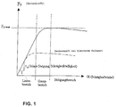
- the so-called lateral acceleration branch in which the recirculated lateral acceleration "by” is taken into account, is usually only outside the linear range of the dependence of the side force ("Fy”) on the slip angle (“ ⁇ ”) relevant, ie only if one moves in the border area or in the saturation region according to Fig.1
- the value for the controller command when the signals "rsoll_acker” and “r_by_filt” have different signs, the value for the controller command, the here and in the already repeatedly mentioned DE 100 09 921 A1 as resulting yaw rate setpoint "rsoll_res" is or was, too Set to zero.
- the proposed zeroing of the resulting yaw rate setpoint Minimum formation or the controller's command in case of different Sign of the input signals of the minimum formation creates here desired remedy.
- the stability of the controller can be made with effective transverse slope branch also in said linear range below the tire saturation.
- the time constant "T" can be set so that the damping of the control loop with and without effective lateral acceleration branch is equally good.
- an offset in the lateral acceleration sensor or a ride in a banked curve ie the above-mentioned possible causes of stability inconsistencies
- the driver only has to apply a slightly larger steering angle than when driving through a flat, level curve with the same curve radius.
- Equation [7] means here that the function value is limited by a ⁇ b and assumes the value x for a ⁇ x ⁇ b, assumes the value a for x ⁇ a and assumes the value b for x> b.
- the size "rsoll_acker” is important insofar as when the driver of the vehicle tries to counteract instability of the vehicle by countersteering, the applied yaw rate control should support or increase its countersteering.
- the countersteering of the driver then goes via the steering wheel angle to "rsoll_acker" in the limitation of "r_by_filt” to the signal controller command “rsoll_res” and from there into said simplified controller command "fb” ultimately to the commanding position for the steering angle of the steerable Fzg.-wheels actuator.
- This resulting controller structure is shown in FIG .
- This dynamic adjustment can now be adapted to the measures introduced in the present patent application, namely by supplementing this with an additional steering reserve which can be described by a DT1 element.
- FIG. 8 shows this structure, in which the quotient of vehicle lateral acceleration and vehicle speed for forming a derivative value is reduced by a float angle velocity calculated using a steering angle-dependent model, for which purpose, if said filtering of the quotient of vehicle lateral acceleration and vehicle speed takes place in the form of a delay element, a resulting phase delay by a differential element DT1 is essentially reversed graphically.
Abstract
Description
Die Erfindung betrifft ein Verfahren zur Erhöhung der Fahrstabilität bei einem Fahrzeug, welches durch einen Regeleingriff am Fahrzeug ein einer Fahrzeug-Instabilität entgegenwirkendes Giermoment bewirkt und wobei das Maß des Regeleingriffes von einem Reglerkommando abhängt, welches in Abhängigkeit von der Differenz aus dem Quotienten von Fahrzeugquerbeschleunigung ("by") und Fahrzeuggeschwindigkeit ("V") einerseits und der tatsächlich auftretenden Gierrate ("r") andererseits bestimmt wird, derart, dass das Reglerkommando auch abhängig vom Minimum aus den Absolutwerten des geeignet gefilterten Quotienten aus Fahrzeugquerbeschleunigung und Fahrzeuggeschwindigkeit einerseits und eines in Abhängigkeit vom Fahrer-Lenkwinkel ("δ L ") vorzugsweise unter Verwendung der Ackermann-Beziehung berechneten Gierraten-Sollwertes ("rsoll_acker") andererseits gewählt wird.The invention relates to a method for increasing the driving stability in a vehicle, which causes a vehicle instability counteracting yaw moment by a control intervention on the vehicle and wherein the degree of the control intervention depends on a controller command, which depends on the difference between the quotient of vehicle lateral acceleration ( "by") and vehicle speed ("V") on the one hand and the actually occurring yaw rate ("r") on the other hand is determined, such that the governor command also depends on the minimum of the suitably filtered quotient of vehicle lateral acceleration and vehicle speed on the one hand and an in Depending on the driver steering angle ("δ L ") is preferably selected using the Ackermann relationship calculated yaw rate setpoint ("rsoll_acker") on the other hand.
Die deutsche Offenlegungsschrift DE 100 09 921 A1 beschreibt diesen im
Oberbegriff des Anspruchs 1 der vorliegenden Patentanmeldung wiedergegebenen
bekannten Stand der Technik. Mit der vorliegenden Patentanmeldung
wird dabei ausdrücklich auf unsere ältere, vorveröffentlichte deutsche
Patentanmeldung 100 09 921.1 sowie unsere weitere, darauf aufbauende
deutsche Patentanmeldung 101 41 273.8 Bezug genommen, weshalb der
Inhalt dieser beiden Anmeldungen und insbesondere der erstgenannten, auf
der auch die vorliegende Anmeldung aufbaut, hier nicht ausführlich
wiederholt wird. The German patent application DE 100 09 921 A1 describes this in the
Preamble of
Diese genannte DE 100 09 921 A1 beschreibt einen sog. Querbeschleunigungszweig in einem Regelkreis für ein elektronisch initiierte Eingriffe erlaubendes Fzg.-Lenksystem, wobei ein Reglerkommando aus einer Minimumbildung zwischen den Absolutwerten des geeignet gefilterten Quotienten aus der Fahrzeugquerbeschleunigung und der Fahrzeuggeschwindigkeit einerseits und eines in Abhängigkeit vom Fahrer-Lenkwinkel unter Verwendung der Ackermann-Beziehung berechneten Gierraten-Sollwertes andererseits gewählt wird. Hierdurch kann bei einer vorliegenden Reifensättigung der lenkwinkelabhängige Gierratensollwert reduziert werden, falls er zu groß ist. In diesen Fällen kann dann mit Hilfe der Fzg.-Querbeschleunigung bzw. dem besagten Quotienten aus der Querbeschleunigung und der Fzg.-Geschwindigkeit ein besserer, vom Betrag reduzierter Ersatzwert für den Gierraten-Sollwert erzeugt werden. Insbesondere gemäß unserer oben zweitgenannten deutschen Patentanmeldung 101 41 273.8 kann der genannte Quotient (dort sowie in der vorliegenden Anmeldung mit "r_by" bezeichnet) noch durch additive lenkwinkelabhängige Signale in seiner Dynamik an den Verlauf des vorzugsweise unter Verwendung der Ackermann-Beziehung berechneten Gierraten-Sollwertes (dort sowie hier mit "rsoll_acker" bezeichnet) angeglichen werden, woraus ein sog. gefilterter Quotient (aus der Querbeschleunigung "by" und der Fzg.-Geschwindigkeit "V") ermittelt werden kann, der hier nun mit "r_by_filt" bezeichnet wird.This mentioned DE 100 09 921 A1 describes a so-called lateral acceleration branch in a control loop for an electronically initiated intervention allowing Fzg.-steering system, with a controller command from a Minimum formation between the absolute values of the suitably filtered Quotients of the vehicle lateral acceleration and the vehicle speed on the one hand and one depending on the driver's steering angle yaw rate setpoint calculated using the Ackermann relationship on the other hand. This can be at a present Tire saturation, the steering angle-dependent yaw rate set point can be reduced if he is too big. In these cases, then with the help of Fzg. Lateral acceleration or the said quotient of the lateral acceleration and the vehicle speed a better, reduced by the amount Substitute value for the yaw rate setpoint can be generated. In particular according to our above-mentioned second German patent application 101 41 273.8 can the quotient mentioned (there and in the present application with "r_by") still by additive steering angle dependent signals in its dynamics to the course of preferably using the Ackermann relationship calculated yaw rate setpoint (there and here with "rsoll_acker"), resulting in a so-called filtered Quotient (from the lateral acceleration "by" and the vehicle speed "V") can be determined, which is now called "r_by_filt".
Lediglich für die Vollständigkeit der vorliegenden Beschreibung wird kurz auf die beigefügte Figur 1 verwiesen, die als sog. Seitenkraft-Diagramm die Abhängigkeit der Seitenkraft ("Fy") eines Reifens oder einer gesamten Achse vom Schräglaufwinkel ("α") graphisch zeigt. Wie bereits in der o.g. DE 100 09 921 A1 beschrieben ist, besitzt diese (Reifen)-Kennlinie zunächst einen Linearbereich, an den sich über einen sog. Grenzbereich der Bereich der Reifen-Sättigung anschließt und der fahrdynamisch relativ kritisch ist, da man dann trotz Erhöhung des Schräglaufwinkelbetrags praktisch keine weitere Erhöhung der Seitenkraft erreichen kann. Only for the completeness of the present description, reference is made briefly to the accompanying Figure 1 , which shows as a so-called side force diagram, the dependence of the lateral force ("Fy") of a tire or an entire axis of the slip angle ("α") graphically. As already described in the above-mentioned DE 100 09 921 A1, this (tire) characteristic curve initially has a linear region to which the region of tire saturation adjoins via a so-called border region and which is relatively critical in terms of driving dynamics since it is then achieved Increasing the slip angle amount can achieve virtually no further increase in lateral force.
Nach dem genannten bekannten Stand der Technik vergleicht die genannte
Minimumbildung die Absolutwerte bzw. Beträge von "r_by_filter" und von
"rsoll_acker" miteinander, woraus für den Absolutwert des resultierenden
Reglerkommandos ("rsoll_res" genannt) die folgende Gleichung gilt:
Demzufolge wirkt der sog. Querbeschleunigungszweig immer dann auf die
Bildung des Gierratensollwertes ein, wenn die folgende Bedingung [2] erfüllt
ist:
Wie im genannten Stand der Technik ausgeführt ist, ist der lenkwinkelabhängige Gierraten-Sollwert "rsoll_acker" dann ausreichend, wenn keine Reifensättigung vorliegt und sich der Reifen folglich im sog. Linearbereich des Seitenkraftdiagramms befindet, so dass dann der sog. Querbeschleunigungszweig, nämlich "r_by_filt" überhaupt nicht wirksam werden muss. Tatsächlich soll dieser sog. Querbeschleunigungszweig nur im Grenzbereich oder Sättigungsbereich (vgl. Fig.1) des Reifens eingreifen.As stated in the cited prior art, the steering angle-dependent yaw rate setpoint "rsoll_acker" is then sufficient if there is no tire saturation and the tire is consequently in the so-called linear region of the lateral force diagram, so that then the so-called lateral acceleration branch, namely "r_by_filt" does not have to be effective at all. In fact, this so-called lateral acceleration branch should intervene only in the boundary region or saturation region (cf.
Wenn man nun die Stabilität des Reglers analysieren will, so hat hierauf ein Vorsteuerkommando keinen Einfluss und es kann auch die Bildung des Gierraten-Sollwertes unberücksichtigt bleiben. Für eine Stabilitätsanalyse müssen folglich nur die Rückführungen im Regelkreis betrachtet werden. Dann wird das Reglerkommando nur noch aus dem Anteil der Gierratenrückführung sowie dem eventuell wirksamen Querbeschleunigungszweig gebildet. Dieses spezielle vereinfachte Reglerkommando wird im weiteren mit "fb" bezeichnet.If one now wants to analyze the stability of the regulator, then one has to Pre-tax command has no influence and it can also the formation of the Yaw rate setpoint ignored. For a stability analysis Consequently, only the feedbacks in the control loop must be considered. Then the governing body only from the proportion of yaw rate feedback and the possibly effective lateral acceleration branch educated. This special simplified controller command will be added later denoted by "fb".
Zur Herleitung der vorliegenden Erfindung wird nun zunächst davon ausgegangen, dass der die Querbeschleunigung "by" verarbeitende sog. For the derivation of the present invention will now be first of it assumed that the lateral acceleration "by" processing so-called.
Querbeschleunigungszweig nicht wirksam sei, woraus sich das genannte
vereinfachte Reglerkommando wie folgt ergibt:
Wie in der bereits mehrfach genannten DE 100 09 921 A1 ausgeführt ist, ist der sog. Querbeschleunigungszweig, in dem die rückgeführte Querbeschleunigung "by" berücksichtigt wird, zumeist nur außerhalb des Linearbereichs der Abhängigkeit der Seitenkraft ("Fy") vom Schräglaufwinkel ("α") relevant, d.h. nur dann, wenn man sich im Grenzbereich oder im Sättigungsbereich gemäß Fig.1 bewegtAs stated in the already repeatedly cited DE 100 09 921 A1, the so-called lateral acceleration branch, in which the recirculated lateral acceleration "by" is taken into account, is usually only outside the linear range of the dependence of the side force ("Fy") on the slip angle ("α ") relevant, ie only if one moves in the border area or in the saturation region according to Fig.1
Es gibt jedoch weitere Situationen, die dazu führen, dass der sog. Querbeschleunigungszweig wirksam ist, und zwar auch dann, wenn das Fzg. noch im genannten Linearbereich des Seitenkraftdiagramms gemäß Fig.1 bewegt wird. Betrachtet man die obigen Gleichungen [1] und [2], so ergibt sich, dass dies für all jene Fälle gilt, in denen die Querbeschleunigung "by" aufgrund irgendwelcher Einflüsse derart verfälscht ist, dass sie vom Betrag her kleiner wird als es den eigentlichen Umständen entspricht. Dies kann bspw. dann der Fall sein, wenn im Querbeschleunigungssensor ein Offset vorhanden ist, oder wenn das Fzg. durch eine sog. Steilwandkurve bewegt wird, bei welcher bekanntermaßen die Fahrbahn in Richtung zum Kurvenmittelpunkt hin abfallend geneigt ist. Nun hat sich gezeigt, dass in solchen Fällen geringfügige Stabilitätsunstimmigkeiten auftreten können. Ursächlich hierfür ist, dass im genannten Linearbereich der Abhängigkeit der Reifenseitenkraft ("Fy") vom Schräglaufwinkel ("α") die Schräglaufsteifigkeit größer als im Bereich der genannten Reifensättigung ist. Mit dem genannten Faktor "k" ist jedoch eine Stabilität nur für obige Gleichung [3], nicht jedoch für Gleichung [4] einstellbar.However, there are other situations that cause the so-called lateral acceleration branch to be effective, even if the vehicle is still being moved in the mentioned linear region of the lateral force diagram according to FIG . Considering the above equations [1] and [2], it follows that this applies to all those cases in which the lateral acceleration "by" is so falsified due to any influences that it becomes smaller in magnitude than the actual one Corresponds to circumstances. This may, for example, be the case if there is an offset in the lateral acceleration sensor, or if the vehicle is moved by a so-called steep wall curve, in which the roadway is known to slope sloping towards the center of the curve. Now it has been shown that in such cases minor stability mismatches can occur. The reason for this is that in the mentioned linear region of the dependence of the tire side force ("Fy") on the slip angle ("α"), the skew stiffness is greater than in the range of said tire saturation. However, with the said factor "k", stability is adjustable only for the above equation [3], but not for the equation [4].
Würde man nun auf gängige Weise diese Unstimmigkeiten beheben wollen, so könnte man die Stabilitätsreserven für den Fall der Gleichung [4] durch möglichst weitgehende Verringerung der Phasenverzögerung verbessern, was jedoch keinen Erfolg bringt, da die inhärenten Phasenverzögerungen entweder physikalischer Natur und somit unvermeidbar sind, und da die bekannten Vorhaltefilter wegen ihrer Messrauschverstärkung nicht verwendbar sind.If you wanted to fix these discrepancies in the usual way, so one could pass the stability reserves for the case of equation [4] improve as far as possible a reduction of the phase delay, which, however, does not bring success because of the inherent phase delays either physical nature and thus unavoidable, and since the known Vorhaltefilter because of their Meßrauschverstärkung not usable are.
Theoretisch könnte man auch durch Einführen einer weiteren Verstärkung
(hier "k2" genannt) im sog. Querbeschleunigungszweig die Stabilitätsreserven
für den Fall der Gleichung [4] verbessern, womit sich Gleichung [5]
ergäbe:
Eine demgegenüber praktikable Abhilfemaßnahme für die weiter oben geschilderte Problematik aufzuzeigen, ist daher Aufgabe der vorliegenden Erfindung.A viable remedy for the above To illustrate problems described, is therefore the task of the present Invention.
Die Lösung dieser Aufgabe ist dadurch gekennzeichnet, das Reglerkommando in den Fällen, in denen der gefilterte Quotient aus Fahrzeugquerbeschleunigung und Fahrzeuggeschwindigkeit einerseits und der Gierraten-Sollwert andererseits unterschiedliche Vorzeichen haben, den Wert "Null" annimmt. Vorteilhafte Weiterbildungen sind Inhalt der Unteransprüche.The solution to this problem is characterized by the controller command in cases where the filtered quotient of vehicle lateral acceleration and vehicle speed on the one hand and the yaw rate setpoint on the other hand have different signs, the value "zero" accepts. Advantageous developments are content of the dependent claims.
Erfindungsgemäß wird dann, wenn die Signale "rsoll_acker" und "r_by_filt" unterschiedliche Vorzeichen haben, der Wert für das Reglerkommando, das hier sowie in der bereits mehrfach genannten DE 100 09 921 A1 als resultierender Gierratensollwert "rsoll_res" bezeichnet wird bzw. wurde, zu "Null" gesetzt. Hierdurch wird vermieden, dass die Größe "r_by_filt" mit umgekehrtem Vorzeichen, d.h. an der Abszisse gespiegelt, den resultierenden Gierratensollwert ergibt, denn eine solche Vorzeichenumkehr hätte unerwünschte Auswirkungen auf die Stabilität und ist daher zu vermeiden. Die vorgeschlagene Nullsetzung des resultierenden Gierraten-Sollwerts der Minimumbildung bzw. des Reglerkommandos im Falle unterschiedlicher Vorzeichen der Eingangssignale der Minimumbildung schafft hier die gewünschte Abhilfe.According to the invention, when the signals "rsoll_acker" and "r_by_filt" have different signs, the value for the controller command, the here and in the already repeatedly mentioned DE 100 09 921 A1 as resulting yaw rate setpoint "rsoll_res" is or was, too Set to zero. This avoids the size "r_by_filt" with opposite sign, i. mirrored on the abscissa, the resulting Yaw rate setpoint, because such a sign reversal would have undesirable effects on stability and should therefore be avoided. The proposed zeroing of the resulting yaw rate setpoint Minimum formation or the controller's command in case of different Sign of the input signals of the minimum formation creates here desired remedy.
Sehr hilfreich ist im übrigen die aus der gattungsbildenden
DE 100 09 921 A1 bzw. dem bekannten Stand der Technik zur vorliegenden
Erfindung bereits bekannte Einführung eines Verzögerungsgliedes im sog.
Querbeschleunigungszweig zur Verbesserung des Stabilitätsverhaltnes des
Regelkreises. Beispielsweise mit einem Verzögerungsglied erster Ordnung
(bspw. mit der bekannten Übertragungsfunktion {Ts+1}-1) im Querbeschleunigungszweig,
das eine geeignete Filterung des Quotienten aus der
Fahrzeugquerbeschleunigung und der Fahrzeuggeschwindigkeit darstellt,
ergibt sich die folgende Gleichung [6] für das vereinfachte Reglerkommando
"fb":
Damit kann die Stabilität des Reglers mit wirksamen Querbescheunigungszweig auch im genannten Linearbereich unterhalb der Reifensättigung hergestellt werden. Die Zeitkonstante "T" kann dabei so eingestellt werden, dass die Dämpfung des Regelkreises mit und ohne wirksamen Querbeschleunigungszweig gleich gut ist. Zwar erzeugt dann ein Offset im Querbeschleunigungssensor oder eine Fahrt in einer Steilwandkurve (d.h. die oben geschilderten möglichen Ursachen für Stabilitätsunstimmigkeiten) weiterhin einen Eingriff durch den Regler, jedoch ist dieser dann stabil und daher nicht weiter störend. Der Fahrer muss also in diesem Fall (also bei Durchfahren einer Steilwandkurve) lediglich einen etwas größeren Lenkwinkel aufbringen als beim Durchfahren einer flachen, ebenen Kurve mit dem selben Kurvenradius. Mit einem derartigen Verzögerungsglied im Querbeschleunigungszweig ergibt sich somit die in Fig.4 dargestellte Struktur des Regelkreises.Thus, the stability of the controller can be made with effective transverse slope branch also in said linear range below the tire saturation. The time constant "T" can be set so that the damping of the control loop with and without effective lateral acceleration branch is equally good. Although then generates an offset in the lateral acceleration sensor or a ride in a banked curve (ie the above-mentioned possible causes of stability inconsistencies) continues to be engaged by the controller, but this is then stable and therefore not disturbing. In this case (ie when driving through a banked curve), the driver only has to apply a slightly larger steering angle than when driving through a flat, level curve with the same curve radius. With such a delay element in the lateral acceleration branch , the structure of the control loop shown in FIG . 4 thus results.
Zurückkommend auf die erfindungsgemäße Null-Setzung der Reglerkommandos
bzw. des resultierender Gierratensollwertes "rsoll_res" kann die
entsprechend abgewandelte Minimumbildung dabei auch als fallbasierte
Anweisung geschrieben werden oder in Form ein sog. Begrenzungsglieds
umgesetzt sein, in dem die Werte für den geeignet gefilterten Quotienten
aus Fahrzeugquerbeschleunigung und Fahrzeuggeschwindigkeit einerseits
und den in Abhängigkeit vom Fahrer-Lenkwinkel berechneten Gierraten-Sollwert
andererseits verglichen werden, woraus sich das folgenden
Reglerkommando ergibt:
Das genannte Begrenzungsglied lässt sich dabei durch die folgende
Gleichung [7] beschreiben :

mit a = rsoll_acker und b = 0, falls rsoll_acker < 0 ist.The mentioned limiting element can be described by the following equation [7]:
with a = rsoll_acker and b = 0, if rsoll_acker <0.
Die in Gleichung [7] enthaltene Funktion
![]()
![]()
Anhand der beigefügten Figuren 5 und 6 wird diese Begrenzung wird durch zwei Beispiele illustriert. In der Darstellung gemäß Fig. 5 ist der Wert "rsoll_acker" < 0 und in derjenigen nach Fig. 6 ist der Wert "rsoll_acker" > 0. Die lenkwinkelabhängige Sollgierrate "rsoll_acker" wird also jetzt nur noch als eine der beiden Grenzen im Begrenzungsglied benutzt. Dabei ist anzumerken, dass dieses vorgeschlagene Begrenzungsglied die in der genannten DE 100 09 921 A1 (sowie in unserer deutschen Patentanmeldung 100 41 273.8) enthaltene Minimumbildung quasi erweitert.With reference to the attached Figures 5 and 6, this limitation will be illustrated by two examples. In the view of FIG. 5, the value "rsoll_acker"<0 and that of FIG. 6, the value "rsoll_acker"is> 0. The steering angle-dependent target yaw rate "rsoll_acker" is therefore now only used as one of the two limits in the limiting element , It should be noted that this proposed limiting element quasi extends the minimum formation contained in the aforementioned DE 100 09 921 A1 (as well as in our German patent application 100 41 273.8).
Bevorzugt wird die Größe "rsoll_acker" dabei derart appliziert, dass im
Stationärfall die folgende Gleichung [8] gilt, d.h. dass im Stationärfall der
Gierraten-Sollwert größer als der genannte und geeignet gefilterte Quotient
aus Fahrzeugquerbeschleunigung und Fahrzeuggeschwindigkeit ist.:
Dabei ist die Größe "rsoll_acker" insofern wichtig, als dann, wenn der Fahrer des Fahrzeugs versucht, einer Instablität des Fzg's durch Gegenlenken entgegenzuwirken, die applizierte Gierratenregelung sein Gegenlenken unterstützen bzw. vergrößern soll. Das Gegenlenken des Fahrers geht dann über den Lenkradwinkel zu "rsoll_acker" in die Begrenzung von "r_by_filt" zum Signal Reglerkommando "rsoll_res" und von da ins genannte vereinfachte Reglerkommando "fb" letztlich zum Stellkommando für den den Lenkeinschlag der lenkbaren Fzg.-Räder bestimmenden Aktuator. Diese resultierende Regler-Struktur ist in Figur 7 gezeigt.The size "rsoll_acker" is important insofar as when the driver of the vehicle tries to counteract instability of the vehicle by countersteering, the applied yaw rate control should support or increase its countersteering. The countersteering of the driver then goes via the steering wheel angle to "rsoll_acker" in the limitation of "r_by_filt" to the signal controller command "rsoll_res" and from there into said simplified controller command "fb" ultimately to the commanding position for the steering angle of the steerable Fzg.-wheels actuator. This resulting controller structure is shown in FIG .
Im weiteren wird eine vorteilhafte Weiterbildung der vorliegenden Erfindung
beschrieben, die im Ansatz bereits in der eingangs genannten deutschen
Patentanmeldung 101 41 273.8 enthalten ist, nämlich ein sog. Dynamikangleich,
der nun hier an das Verfahren nach dem vorliegenden Patentanspruch
1 angepasst wird. Zunächst diesen sog. Dynamikangleich erläuternd
hat sich gezeigt, dass eine unterschiedliche Dynamik in den Verläufen von
"rsoll_acker" und "r_by" vorliegt, und zwar insbesondere im linearen
Querdynamikbereich des Fahrzeugs, der mit dem linearen Teil der Reifenkennlinie
gleichgesetzt werden kann. Grundsätzlich wäre jedoch eine
Dynamik für "r_by" wie vom "rsoll_acker"-Signal wünschenswert, so dass
dann "r_by" bei dynamischen Übergängen ohne Reifensättigung keinen
Einfluß auf den Giersollwert "rsoll_res" hätte. In der genannten nicht
vorveröffentlichten deutschen Patentanmeldung 101 41 273.8 ist nun
beschrieben, (und hierauf wird im Rahmen der vorliegenden Anmeldung
ausdrücklich Bezug genommen ) wie dem Signal der Querbeschleunigung
"r_by" das dynamische Verhalten der Größe "rsoll_acker" aufgeprägt werden
kann, d.h. wie ein Dynamikangleich von "r_by" an die Gierratensollwerte der
Modellvorsteuerungen erfolgen kann.In addition, an advantageous embodiment of the present invention
described in the approach already in the aforementioned German
Patent application 101 41 273.8 is included, namely a so-called. Dynamikreleich,
now here to the method according to the
Dabei soll im genannten Linearbereich der Abhängigkeit der Seitenkraft
("Fy") vom Schräglaufwinkel ("α") das Signal "r_by" keinen Einfluss auf das
Stellkommando haben. Erst wenn die Reifensättigung wirksam wird und der
Wert von "r_by" absinkt, sollte "r_by" wirksam werden. Um dies zu gewährleisten,
wurde vorgeschlagen, dass dem Signal "r_by" ein anderes Signal
hinzuaddiert wird, das durch ein oder mehrere in den Modellvorsteuerungen
enthaltene(s/n) Einspurmodell(e) ohne Schwierigkeiten zur Verfügung steht,
nämlich die Schwimmwinkelgeschwindigkeit β ˙. Dieser soweit vorbekannte
Dynamikangleich lässt sich also durch die folgende Gleichung [9] beschreiben:
Dieser Dynamikangleich kann nun an die in mit der vorliegenden Patentanmeldung
eingeführten Maßnahmen angepasst werden, und zwar indem
dieser durch einen zusätzlichen Lenkvorhalt, der durch ein DT1-Glied
beschreibbar ist, ergänzt wird. Dieses DT1-Glied greift die Beschleunigung
byMod aus einem lenkwinkelabhängigen Einspurmodell ab, so dass man die
folgende Gleichung [10] erhält:
Dadurch wird eine durch das PT1-Glied in Gleichung [6] erzeugte Phasenverzögerung wieder rückgängig gemacht, wonach im genannten Linearbereich der Abhängigkeit der Reifenseitenkraft ("Fy") vom Schräglaufwinkel ("α") der Verlauf von "r_by_filt" wieder dem Verlauf der gemessenen Gierrate "r" gleicht und somit das vereinfachte Reglerkommando "fb" auf dem Wert "Null" bleibt. Abweichungen der beiden Signale können sich dann nur noch durch die Modellungenauigkeiten des Einspurmodells ergeben, die aber relativ klein sind.Thereby, a phase delay generated by the PT1 element in equation [6] becomes undone, after which in the mentioned linear range the dependence of the tire side force ("Fy") on the slip angle ("α") the course of "r_by_filt" again the course of the measured yaw rate "r" equals the simplified controller command "fb" on the value "Zero" remains. Deviations of the two signals can then only through the model inaccuracies of the one-track model, but that are relatively small.
Die Stabiltät der Querbeschleunigungsrückführung wird dabei nicht angetastet,
da die Addition von
Mit den vorgeschlagenen Maßnahmen lässt sich also die Zuverlässigkeit des
Verfahrens nach Anspruch 1 erheblich steigern, wobei noch darauf hingewiesen
sei, dass durchaus eine Vielzahl von Details abweichend von obigen
Ausführungen gestaltet sein kann, ohne den Inhalt der Patentansprüche zu
verlassen.The proposed measures thus allow the reliability of the
Significantly increase the method of
Claims (5)
dadurch gekennzeichnet, dass das Reglerkommando in den Fällen, in denen der gefilterte Quotient aus Fahrzeugquerbeschleunigung und Fahrzeuggeschwindigkeit einerseits und der Gierraten-Sollwertes andererseits unterschiedliche Vorzeichen haben, den Wert "Null" annimmt.Method for increasing the driving stability in a vehicle, which causes by a control intervention on the vehicle a vehicle instability counteracting yaw moment and wherein the degree of control intervention depends on a regulator command, which depends on the difference between the quotient of vehicle lateral acceleration and vehicle speed on the one hand and the On the other hand, the yaw rate actually occurring is determined in such a way that the governor command is also selected as a function of the minimum of the suitably filtered quotient of vehicle lateral acceleration and vehicle speed on the one hand and a yaw rate target value calculated as a function of the driver steering angle, preferably using the Ackermann relationship .
characterized in that the controller command in the cases in which the filtered quotient of vehicle lateral acceleration and vehicle speed on the one hand and the yaw rate setpoint on the other hand have different signs, assumes the value "zero".
dadurch gekennzeichnet, dass die Minimumbildung in Form ein sog. Begrenzungsglieds umgesetzt ist, in dem die Werte für den geeignet gefilterten Quotienten aus Fahrzeugquerbeschleunigung und Fahrzeuggeschwindigkeit einerseits und den in Abhängigkeit vom Fahrer-Lenkwinkel berechneten Gierraten-Sollwert andererseits verglichen werden, woraus sich das folgenden Reglerkommando ergibt:
characterized in that the minimum formation is implemented in the form of a so-called limiting element in which the values for the suitably filtered quotient of vehicle lateral acceleration and vehicle speed on the one hand and the yaw rate command value calculated on the basis of the driver steering angle are compared on the other hand, resulting in the following governor command results:
dadurch gekennzeichnet, dass im Stationärfall der Gierraten-Sollwert größer als der genannte und geeignet gefilterte Quotient aus Fahrzeugquerbeschleunigung und Fahrzeuggeschwindigkeit ist.Method according to claim 1 or 2,
characterized in that in the stationary case, the yaw rate setpoint is greater than said and suitably filtered quotient of vehicle lateral acceleration and vehicle speed.
dadurch gekennzeichnet, dass der Quotient von Fahrzeugquerbeschleunigung und Fahrzeuggeschwindigkeit zur Bildung eines Vorhaltewertes um eine mit Hilfe eines lenkwinkelabhängigen Modells berechnete Schwimmwinkelgeschwindigkeit verringert wird.Method according to one of the preceding claims,
characterized in that the quotient of vehicle lateral acceleration and vehicle speed for forming a Vorhaltewertes is reduced by a calculated using a steering angle-dependent model Schwimmwinkelgeschwindigkeit.
dadurch gekennzeichnet, dass falls die genannte Filterung des Quotienten aus Fahrzeugquerbeschleunigung und Fahrzeuggeschwindigkeit in Form eines Verzögerungsgliedes erfolgt, eine daraus resultierende Phasenverzögerung durch ein Differentialglied im wesentlichen wieder rückgängig gemacht wird.Method according to claim 4,
characterized in that if the said filtering of the quotient of vehicle lateral acceleration and vehicle speed takes place in the form of a delay element, a resulting phase delay by a differential element is essentially reversed.
Applications Claiming Priority (2)
| Application Number | Priority Date | Filing Date | Title |
|---|---|---|---|
| DE10221717 | 2002-05-16 | ||
| DE10221717A DE10221717A1 (en) | 2002-05-16 | 2002-05-16 | Method for increasing driving stability in a vehicle |
Publications (2)
| Publication Number | Publication Date |
|---|---|
| EP1362754A1 true EP1362754A1 (en) | 2003-11-19 |
| EP1362754B1 EP1362754B1 (en) | 2004-10-13 |
Family
ID=29265316
Family Applications (1)
| Application Number | Title | Priority Date | Filing Date |
|---|---|---|---|
| EP03007325A Expired - Lifetime EP1362754B1 (en) | 2002-05-16 | 2003-04-01 | Vehicle stability enhancing method |
Country Status (2)
| Country | Link |
|---|---|
| EP (1) | EP1362754B1 (en) |
| DE (2) | DE10221717A1 (en) |
Cited By (2)
| Publication number | Priority date | Publication date | Assignee | Title |
|---|---|---|---|---|
| EP1426258A1 (en) * | 2002-11-26 | 2004-06-09 | Toyota Jidosha Kabushiki Kaisha | Behavior control system for vehicle |
| EP1652752A2 (en) * | 2004-11-01 | 2006-05-03 | HONDA MOTOR CO., Ltd. | Ackerman angle based vehicle steering angle correction |
Families Citing this family (2)
| Publication number | Priority date | Publication date | Assignee | Title |
|---|---|---|---|---|
| DE102004035004A1 (en) | 2004-07-20 | 2006-02-16 | Bayerische Motoren Werke Ag | Method for increasing the driving stability of a motor vehicle |
| DE102005005152A1 (en) * | 2005-02-04 | 2006-08-10 | Bayerische Motoren Werke Ag | Signal e.g. yaw rate measuring signal, identifying method for motor vehicle, involves forming signal corrected from measuring signal noise by addition of intermediate signal and average value |
Citations (4)
| Publication number | Priority date | Publication date | Assignee | Title |
|---|---|---|---|---|
| US6092882A (en) * | 1996-08-01 | 2000-07-25 | Fuji Jukogyo Kabushiki Kaisha | Braking force control system and the method thereof |
| DE10009921A1 (en) | 2000-03-01 | 2001-07-19 | Bayerische Motoren Werke Ag | Method for increasing drive stability of vehicle sets level of control dependent on regulator commando determined in dependence on difference of quotients of vehicle cross acceleration and vehicle speed and the current yaw rate |
| DE10105710A1 (en) * | 2000-02-08 | 2001-09-06 | Koyo Seiko Co | Steering system for vehicles |
| DE10141273A1 (en) | 2001-08-23 | 2003-03-20 | Bayerische Motoren Werke Ag | Increasing vehicle driving stability by applying yaw moment to counter instability, involves taking lower and larger yaw rate demand values into account if actual yaw rate lies between them |
-
2002
- 2002-05-16 DE DE10221717A patent/DE10221717A1/en not_active Withdrawn
-
2003
- 2003-04-01 DE DE2003500107 patent/DE50300107D1/en not_active Expired - Lifetime
- 2003-04-01 EP EP03007325A patent/EP1362754B1/en not_active Expired - Lifetime
Patent Citations (4)
| Publication number | Priority date | Publication date | Assignee | Title |
|---|---|---|---|---|
| US6092882A (en) * | 1996-08-01 | 2000-07-25 | Fuji Jukogyo Kabushiki Kaisha | Braking force control system and the method thereof |
| DE10105710A1 (en) * | 2000-02-08 | 2001-09-06 | Koyo Seiko Co | Steering system for vehicles |
| DE10009921A1 (en) | 2000-03-01 | 2001-07-19 | Bayerische Motoren Werke Ag | Method for increasing drive stability of vehicle sets level of control dependent on regulator commando determined in dependence on difference of quotients of vehicle cross acceleration and vehicle speed and the current yaw rate |
| DE10141273A1 (en) | 2001-08-23 | 2003-03-20 | Bayerische Motoren Werke Ag | Increasing vehicle driving stability by applying yaw moment to counter instability, involves taking lower and larger yaw rate demand values into account if actual yaw rate lies between them |
Cited By (4)
| Publication number | Priority date | Publication date | Assignee | Title |
|---|---|---|---|---|
| EP1426258A1 (en) * | 2002-11-26 | 2004-06-09 | Toyota Jidosha Kabushiki Kaisha | Behavior control system for vehicle |
| US7142969B2 (en) | 2002-11-26 | 2006-11-28 | Toyota Jidosha Kabushiki Kaisha | Behavior control system for vehicle |
| EP1652752A2 (en) * | 2004-11-01 | 2006-05-03 | HONDA MOTOR CO., Ltd. | Ackerman angle based vehicle steering angle correction |
| EP1652752A3 (en) * | 2004-11-01 | 2009-04-08 | HONDA MOTOR CO., Ltd. | Ackerman angle based vehicle steering angle correction |
Also Published As
| Publication number | Publication date |
|---|---|
| EP1362754B1 (en) | 2004-10-13 |
| DE50300107D1 (en) | 2004-11-18 |
| DE10221717A1 (en) | 2003-12-11 |
Similar Documents
| Publication | Publication Date | Title |
|---|---|---|
| DE4038079B4 (en) | Vehicle with an anti-skid control | |
| EP0943515B1 (en) | Method for controlling of the yaw-behavior of vehicles | |
| DE10354662B4 (en) | Method and device for assisting the driver of a motor vehicle in driving-dynamic borderline situations | |
| EP1351843B1 (en) | Device and method for operating a motor vehicle | |
| EP1890920B1 (en) | Vehicle dynamics control adapted to driving state and based on steering interventions | |
| DE102010042135B4 (en) | Method for determining a rack force for a steering device in a vehicle | |
| DE102011055339A1 (en) | METHOD FOR DETERMINING A TOOTHPIECE FOR A STEERING DEVICE AND STEERING DEVICE | |
| EP2013069A1 (en) | Method and system for determining an optimal steering angle in understeer situations in a vehicle | |
| DE102005018471A1 (en) | Motor vehicle stabilization method, involves applying driver-independent steering wheel moment, where steering wheel runs smooth in direction of rotation than in opposite direction of rotation | |
| DE102005012548A1 (en) | Steering method for increasing driving stability of vehicle while driving on a curve, involves monitoring understeering condition and transmission ratio, and changing transmission ratio with increasing amount of steering angle | |
| DE102007053815B4 (en) | Device for operating an active steering of a motor vehicle and method for operating an active steering a front axle of a motor vehicle | |
| WO2008046586A2 (en) | Method for regulating the yaw rate of a motor vehicle | |
| DE102005012584A1 (en) | Driving stability method e.g. for enhancing driving stability of vehicle during driving through curve, involves adjusting steering movement in relation to driver default initiated by driver with changed guidance angle at wheel shown | |
| EP1362754B1 (en) | Vehicle stability enhancing method | |
| DE102004008265A1 (en) | Control method for a motor vehicle's wheel drift control system uses a wheel drift/slippage controller to generate adjustment variables for individual wheels | |
| DE102007019698B4 (en) | Method and device for the electrically controlled assisting a driving movement of a vehicle and vehicle | |
| DE102012102629A1 (en) | Method for controlling steering system of motor vehicle, involves controlling controller of steering force through one way path and feedback of steering force through return path, and integrating gain curves into one way and return paths | |
| DE102008027093A1 (en) | Technology for operating a brake system in a μ-split situation | |
| DE102007008357A1 (en) | Driving dynamics-control system, particularly for double-tracked motor vehicle, has one or multiple controlled actuators to determine lateral rigidity of tire | |
| DE102014004946B4 (en) | Method and system for controlling wheels of a motor vehicle | |
| DE102005028153A1 (en) | Method for controlling a steering device involves increasing of the modified speed signal superproportionally, when the requested speed signal exceeds the reference value | |
| EP2501592A1 (en) | Method for operating a brake system and corresponding controller | |
| DE10245032A1 (en) | Procedure for controlling driving behavior by influencing the yaw rate | |
| DE102007002362B4 (en) | Method for adjusting a steering angle at the front axle of an understeering motor vehicle with the aid of an additional steering and active steering system | |
| DE19542295B4 (en) | Braking system for a vehicle |
Legal Events
| Date | Code | Title | Description |
|---|---|---|---|
| PUAI | Public reference made under article 153(3) epc to a published international application that has entered the european phase |
Free format text: ORIGINAL CODE: 0009012 |
|
| 17P | Request for examination filed |
Effective date: 20030918 |
|
| AK | Designated contracting states |
Kind code of ref document: A1 Designated state(s): AT BE BG CH CY CZ DE DK EE ES FI FR GB GR HU IE IT LI LU MC NL PT RO SE SI SK TR |
|
| AX | Request for extension of the european patent |
Extension state: AL LT LV MK |
|
| GRAP | Despatch of communication of intention to grant a patent |
Free format text: ORIGINAL CODE: EPIDOSNIGR1 |
|
| GRAS | Grant fee paid |
Free format text: ORIGINAL CODE: EPIDOSNIGR3 |
|
| AKX | Designation fees paid |
Designated state(s): DE FR GB IT |
|
| GRAA | (expected) grant |
Free format text: ORIGINAL CODE: 0009210 |
|
| AK | Designated contracting states |
Kind code of ref document: B1 Designated state(s): DE FR GB IT |
|
| REG | Reference to a national code |
Ref country code: GB Ref legal event code: FG4D Free format text: NOT ENGLISH |
|
| GBT | Gb: translation of ep patent filed (gb section 77(6)(a)/1977) |
Effective date: 20041013 |
|
| REG | Reference to a national code |
Ref country code: IE Ref legal event code: FG4D Free format text: GERMAN |
|
| REF | Corresponds to: |
Ref document number: 50300107 Country of ref document: DE Date of ref document: 20041118 Kind code of ref document: P |
|
| REG | Reference to a national code |
Ref country code: IE Ref legal event code: FD4D |
|
| ET | Fr: translation filed | ||
| PLBE | No opposition filed within time limit |
Free format text: ORIGINAL CODE: 0009261 |
|
| STAA | Information on the status of an ep patent application or granted ep patent |
Free format text: STATUS: NO OPPOSITION FILED WITHIN TIME LIMIT |
|
| 26N | No opposition filed |
Effective date: 20050714 |
|
| REG | Reference to a national code |
Ref country code: FR Ref legal event code: PLFP Year of fee payment: 14 |
|
| REG | Reference to a national code |
Ref country code: FR Ref legal event code: PLFP Year of fee payment: 15 |
|
| REG | Reference to a national code |
Ref country code: FR Ref legal event code: PLFP Year of fee payment: 16 |
|
| PGFP | Annual fee paid to national office [announced via postgrant information from national office to epo] |
Ref country code: IT Payment date: 20220429 Year of fee payment: 20 Ref country code: GB Payment date: 20220425 Year of fee payment: 20 Ref country code: FR Payment date: 20220420 Year of fee payment: 20 Ref country code: DE Payment date: 20220421 Year of fee payment: 20 |
|
| REG | Reference to a national code |
Ref country code: DE Ref legal event code: R071 Ref document number: 50300107 Country of ref document: DE |
|
| REG | Reference to a national code |
Ref country code: GB Ref legal event code: PE20 Expiry date: 20230331 |
|
| PG25 | Lapsed in a contracting state [announced via postgrant information from national office to epo] |
Ref country code: GB Free format text: LAPSE BECAUSE OF EXPIRATION OF PROTECTION Effective date: 20230331 |
|
| P01 | Opt-out of the competence of the unified patent court (upc) registered |
Effective date: 20230427 |