EP1362724A1 - Anschlusssystem für eine Kraftfahrzeug-Klimaanlage - Google Patents
Anschlusssystem für eine Kraftfahrzeug-Klimaanlage Download PDFInfo
- Publication number
- EP1362724A1 EP1362724A1 EP03101329A EP03101329A EP1362724A1 EP 1362724 A1 EP1362724 A1 EP 1362724A1 EP 03101329 A EP03101329 A EP 03101329A EP 03101329 A EP03101329 A EP 03101329A EP 1362724 A1 EP1362724 A1 EP 1362724A1
- Authority
- EP
- European Patent Office
- Prior art keywords
- adapter
- pressure switch
- filling
- evacuation
- valve
- Prior art date
- Legal status (The legal status is an assumption and is not a legal conclusion. Google has not performed a legal analysis and makes no representation as to the accuracy of the status listed.)
- Granted
Links
Images


Classifications
-
- B—PERFORMING OPERATIONS; TRANSPORTING
- B60—VEHICLES IN GENERAL
- B60H—ARRANGEMENTS OF HEATING, COOLING, VENTILATING OR OTHER AIR-TREATING DEVICES SPECIALLY ADAPTED FOR PASSENGER OR GOODS SPACES OF VEHICLES
- B60H1/00—Heating, cooling or ventilating devices
- B60H1/00507—Details, e.g. mounting arrangements, desaeration devices
- B60H1/00557—Details of ducts or cables
- B60H1/00571—Details of ducts or cables of liquid ducts, e.g. for coolant liquids or refrigerants
-
- B—PERFORMING OPERATIONS; TRANSPORTING
- B60—VEHICLES IN GENERAL
- B60H—ARRANGEMENTS OF HEATING, COOLING, VENTILATING OR OTHER AIR-TREATING DEVICES SPECIALLY ADAPTED FOR PASSENGER OR GOODS SPACES OF VEHICLES
- B60H1/00—Heating, cooling or ventilating devices
- B60H1/00507—Details, e.g. mounting arrangements, desaeration devices
- B60H1/00585—Means for monitoring, testing or servicing the air-conditioning
-
- F—MECHANICAL ENGINEERING; LIGHTING; HEATING; WEAPONS; BLASTING
- F16—ENGINEERING ELEMENTS AND UNITS; GENERAL MEASURES FOR PRODUCING AND MAINTAINING EFFECTIVE FUNCTIONING OF MACHINES OR INSTALLATIONS; THERMAL INSULATION IN GENERAL
- F16L—PIPES; JOINTS OR FITTINGS FOR PIPES; SUPPORTS FOR PIPES, CABLES OR PROTECTIVE TUBING; MEANS FOR THERMAL INSULATION IN GENERAL
- F16L37/00—Couplings of the quick-acting type
-
- F—MECHANICAL ENGINEERING; LIGHTING; HEATING; WEAPONS; BLASTING
- F25—REFRIGERATION OR COOLING; COMBINED HEATING AND REFRIGERATION SYSTEMS; HEAT PUMP SYSTEMS; MANUFACTURE OR STORAGE OF ICE; LIQUEFACTION SOLIDIFICATION OF GASES
- F25B—REFRIGERATION MACHINES, PLANTS OR SYSTEMS; COMBINED HEATING AND REFRIGERATION SYSTEMS; HEAT PUMP SYSTEMS
- F25B41/00—Fluid-circulation arrangements
- F25B41/40—Fluid line arrangements
-
- F—MECHANICAL ENGINEERING; LIGHTING; HEATING; WEAPONS; BLASTING
- F25—REFRIGERATION OR COOLING; COMBINED HEATING AND REFRIGERATION SYSTEMS; HEAT PUMP SYSTEMS; MANUFACTURE OR STORAGE OF ICE; LIQUEFACTION SOLIDIFICATION OF GASES
- F25B—REFRIGERATION MACHINES, PLANTS OR SYSTEMS; COMBINED HEATING AND REFRIGERATION SYSTEMS; HEAT PUMP SYSTEMS
- F25B45/00—Arrangements for charging or discharging refrigerant
Definitions
- the invention relates to an air conditioning system for motor vehicles, the one Connecting piece for a pressure switch / sensor contains, after removal the pressure switch / sensor to evacuate and fill the air conditioning is suitable, so that the two usually separate functions in one Neck are summarized.
- the invention further relates to a Adapter that makes it possible to have an evacuation and filling unit on one today Common connecting piece for a pressure switch / sensor to join. As a result, the currently used additional arrangement of connecting pieces for the evacuation and filling of the air conditioning superfluous.
- Motor vehicles are usually driven by internal combustion engines. These internal combustion engines are in turn by means of a cooling circuit held at a certain temperature level. For heating the interior a motor vehicle is usually the circulating coolant this Cooling circuit used, which has a heat exchanger and a Blower delivers the heat to the interior.
- the regulation of air conditioners with capillary tubes is usually over a suitable pressure sensitive component such as a pressure switch or Pressure sensor made, which is also in the line between Evaporator and compressor is arranged.
- a suitable pressure sensitive component such as a pressure switch or Pressure sensor made, which is also in the line between Evaporator and compressor is arranged.
- This Pressure switch or pressure sensor is usually via a mounting thread with a correspondingly shaped connection piece on one Air conditioning line attached, the connecting piece is a spring-loaded One-way valve incorporates that in use in its construction Motor vehicle wheel valves is very similar.
- the connecting piece itself is in usually welded or soldered to an air conditioning line.
- a pressure switch or sensor is usually used as High-pressure safety element for switching off the compressor if it is too high Press and is used to control a radiator fan.
- connection piece When filling with refrigerant, service and / or service pipes must be installed on the refrigerant pipes Filler attached. These connecting pieces also contain spring-loaded Valves. About this connection piece are standardized Quick couplings the evacuation and initial filling of the air conditioning carried out or done during the automotive life service work. These connecting pieces are usually at the Air conditioning ducts welded or soldered.
- the usual capacity for an air conditioner of a motor vehicle is today to Vieweg at about 600 to 900g R 134a. Safe operation of the air conditioning is guaranteed, as long as still about 70% of the original capacity in Refrigerant circuit are located.
- the disadvantage of today's air conditioners that small amounts of refrigerant through the hoses and sealing rings of the Air conditioning can escape. It is therefore advantageous the number of Keep sealing points as low as possible.
- connection piece requires an additional soldering operation means a reduction in the number of connecting pieces therefore a significant reduction the number of soldering operations, also results in a slightly lower Material consumption. Furthermore, so two valves can be omitted.
- one or more connecting pieces of an air conditioner used for motor vehicles for mounting of pressure switches or sensors are used.
- a low-pressure switch is used or sensor and / or a high pressure switch / sensor is used.
- everyone Connecting piece is thereby formed so that after removing the Pressure switch / sensor the connection of a quick coupling of an evacuator and Filling unit is possible.
- This will become the more common today Arrangement of connecting pieces for the evacuation and filling of Air conditioning superfluous, thus reducing the number of sealing points. At the same time, this results in cost savings from the reduced Material use and less complex production. It is, however, one Modification of the currently produced in mass production pressure switch / sensors necessary.
- connection piece a valve.
- This valve opens during assembly a pressure switch / sensor or by connecting the quick coupling an evacuation and filling unit and closes automatically during disassembly a pressure switch / sensor or when removing the quick coupling a Evacuation and filling unit.
- This has the advantage that during assembly or Dismounting of pressure switches / sensors and when connecting or disconnecting of quick couplings of an evacuation and filling unit no refrigerant Leave the air conditioning circuit uncontrolled and enter the environment can.
- a further embodiment of the invention provides, after removing a Pressure switch / sensor of the air conditioner first an adapter on the sun To be freed connection piece of the air conditioning to install, then the To be able to connect the evacuation and filling device.
- This embodiment has the advantage that today's mass-produced pressure switch / sensors or quick couplings are used unchanged can. As a result, the usual today additional arrangement of Connecting piece for the evacuation and filling of the air conditioning superfluous.
- the adapter is so designed that the valve in the connection piece when connecting the evacuation and Filling system is opened. As a result, the handling is noticeably easier.
- the one-way valve in Connection piece open when attaching the adapter, so that as in the known operation of an evacuation and filling, the evacuation and Filling device to be connected directly to the air conditioning circuit can.
- both the valve in the Connecting piece as well as the valve in the adapter when connecting the evacuation and Filling system open are noticeably easier.
- an advantageous development of the invention is characterized in that the adapter contains at least two valves. This variant offers a particularly high safety against refrigerant loss.
- valves opens a valve as soon as the adapter is attached to the neck while a second valve is opened when connecting the evacuating and filling device.
- the Ease of use is increased so much.
- the Adapter according to the invention integrated into an evacuation and filling unit. This has the advantage that the adapter according to the invention at any time at the Evacuation and filling system is located and may not be in workshop operation or can be moved during production.
- the adapter at least one further connection or branch on the z. B. for connection a pressure gauge is suitable. Through this at least one branch can be in the adapter more than just the pure connection function for the Integrate evacuation and filling system.
- a development of the invention provides for the at least one Pressure switch / sensor subsectionen so that it has a connection in the manner of a Quick coupling of the evacuation and filling has. So can the common form of filling / service connection piece are maintained, while the usual today additional arrangement of connecting pieces becomes unnecessary for the pressure switch / sensor of the air conditioner.
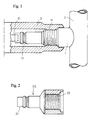
- FIG. 1 shows a schematic drawing of a part of the invention Air conditioning.
- a connecting piece 1 is in the picture with a line 2 of Air conditioning connected cohesively.
- a pressure switch 3 is over the Thread 11 screwed to the connection piece 1.
- a protruding part 31 of the pressure switch 3 keeps open the one-way valve (not shown here), so that a direct pressure measurement of the refrigerant pressure in the line 2 of the Air conditioning is possible.
- the pressure switch 3 is removed, that closes integrated one-way valve.
- the air conditioning line 2 facing away from the Connecting piece 1 is now free and allows the installation of a Quick coupling of an evacuation and filling unit, with the quick coupling in the groove 12 can engage.
- FIG. 2 shows a possible embodiment of the adapter 20 according to the invention shown.
- the end 21 of the adapter 20 is formed so that it is for Mounting a quick coupling of an evacuation and filling unit is suitable.
- the other end 22 of the adapter 20 has a thread which corresponds to the thread of a commonly used pressure switch / sensor, so that a mounting on a connecting piece of an air conditioner for Pressure switch / sensors is possible.
- Figure 3 shows a part of an adapter 20 according to the invention, in which Forming an internal thread 23 on an otherwise known connecting piece 1, which is suitable for connection of an evacuation and filling unit, the Possibility to accommodate a pressure switch 3 was created.
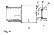
- FIG. 4 shows a pressure switch / sensor (30) according to the invention.
- the end 31 is designed so that it like a quick release an Evakuierund Filling unit can be mounted on a connecting piece.
- the groove 32 contains a spring ring 33, in a known manner at a Quick coupling provides a lock.
- the cylindrical section shown 34 is used during assembly to open the usually in one Connecting piece contained one-way valve.
- FIG. 5 shows a further embodiment of the invention Adapters 20 screwed onto a socket 1 and provided with a additional branch for a pressure switch 3.
Landscapes
- Engineering & Computer Science (AREA)
- Mechanical Engineering (AREA)
- Physics & Mathematics (AREA)
- Thermal Sciences (AREA)
- General Engineering & Computer Science (AREA)
- Air-Conditioning For Vehicles (AREA)
Abstract
Description
Claims (12)
- Klimaanlage für Kraftfahrzeuge mit mindestens einem Anschlußstutzen (1),
dadurch gekennzeichnet, daß
der mindestens eine Anschlußstutzen (1) so ausgeformt ist, daß er wahlweise sowohl für den Anschluß eines Druckschalters (3) als auch für den Anschluß einer Evakuier- und Befülleinrichtung geeignet ist. - Klimaanlage für Kraftfahrzeuge nach Anspruch 1,
dadurch gekennzeichnet, daß
der mindestens eine Anschlußstutzen (1) ein Ventil enthält. - Klimaanlage für Kraftfahrzeuge nach Anspruch 1 oder 2,
dadurch gekennzeichnet, daß
vor dem Anschluß einer Evakuier- und Befülleinrichtung ein Adapter (20) angebracht wird. - Klimaanlage für Kraftfahrzeuge nach Anspruch 3,
dadurch gekennzeichnet, daß
der Adapter (20) so ausgeformt ist, daß beim Anschließen der Evakuierund Befülleinrichtung das Ventil im Anschlußstutzen (1) geöffnet wird. - Klimaanlage für Kraftfahrzeuge nach Anspruch 3,
dadurch gekennzeichnet, daß
der Adapter (20) ein Ventil enthält. - Klimaanlage für Kraftfahrzeuge nach Anspruch 5,
dadurch gekennzeichnet, daß
der Adapter (20) so ausgeformt ist, daß beim Anschließen der Evakuierund Befülleinrichtung sowohl das Ventil im Adapter (20) als auch das Ventil im Anschlußstutzen (1) geöffnet wird. - Klimaanlage für Kraftfahrzeuge nach Anspruch 3,
dadurch gekennzeichnet, daß
der Adapter (20) mindestens zwei Ventile enthält. - Klimaanlage für Kraftfahrzeuge nach Anspruch 7,
dadurch gekennzeichnet, daß
der Adapter (20) so ausgeformt ist, daß beim Anschließen der Evakuierund Befülleinrichtung mindestens ein Ventil im Adapter (20) geöffnet wird. - Klimaanlage für Kraftfahrzeuge nach Anspruch 3, 4, 5, 6 oder 7
dadurch gekennzeichnet, daß
der Adapter (20) in der Evakuier- und Befülleinrichtung integriert ist. - Klimaanlage für Kraftfahrzeuge nach den Ansprüchen 3 bis 9
dadurch gekennzeichnet, daß
der Adapter (20) mindestens einen weiteren Anschluß oder Abzweig ausweist. - Klimaanlage für Kraftfahrzeuge nach Anspruch 10
dadurch gekennzeichnet, daß
der Anschluß oder Abzweig zur Aufnahme eines Druckschalters (3) oder Drucksensors geeignet ist und/oder mit einem Druckschalter (3) oder Drucksensor versehen ist. - Klimaanlage für Kraftfahrzeuge nach Anspruch 1 oder 2,
dadurch gekennzeichnet, daß
der Druckschalter (3) eine Schnellkupplung enthält, die entsprechend der Schnellkupplung einer Evakuier- und Befülleinheit ausgeformt ist.
Priority Applications (1)
| Application Number | Priority Date | Filing Date | Title |
|---|---|---|---|
| EP03101329A EP1362724B1 (de) | 2002-05-14 | 2003-05-14 | Anschlusssystem für eine Kraftfahrzeug-Klimaanlage |
Applications Claiming Priority (3)
| Application Number | Priority Date | Filing Date | Title |
|---|---|---|---|
| EP02100491 | 2002-05-14 | ||
| EP02100491A EP1362722A1 (de) | 2002-05-14 | 2002-05-14 | Anschlussystem für eine Kraftfahrzeug-Klimaanlage |
| EP03101329A EP1362724B1 (de) | 2002-05-14 | 2003-05-14 | Anschlusssystem für eine Kraftfahrzeug-Klimaanlage |
Publications (2)
| Publication Number | Publication Date |
|---|---|
| EP1362724A1 true EP1362724A1 (de) | 2003-11-19 |
| EP1362724B1 EP1362724B1 (de) | 2006-10-04 |
Family
ID=29271892
Family Applications (1)
| Application Number | Title | Priority Date | Filing Date |
|---|---|---|---|
| EP03101329A Expired - Lifetime EP1362724B1 (de) | 2002-05-14 | 2003-05-14 | Anschlusssystem für eine Kraftfahrzeug-Klimaanlage |
Country Status (1)
| Country | Link |
|---|---|
| EP (1) | EP1362724B1 (de) |
Citations (3)
| Publication number | Priority date | Publication date | Assignee | Title |
|---|---|---|---|---|
| US5005375A (en) * | 1989-04-06 | 1991-04-09 | Kent-Moore Corporation | Refrigeration equipment service apparatus with quick-disconnect couplings |
| US5293902A (en) * | 1993-06-07 | 1994-03-15 | Tif Instruments, Inc. | Quick-disconnect fluid coupling |
| US6334320B1 (en) * | 1999-03-30 | 2002-01-01 | Spx Corporation | Electronic manifold for a refrigerant servicing unit |
-
2003
- 2003-05-14 EP EP03101329A patent/EP1362724B1/de not_active Expired - Lifetime
Patent Citations (3)
| Publication number | Priority date | Publication date | Assignee | Title |
|---|---|---|---|---|
| US5005375A (en) * | 1989-04-06 | 1991-04-09 | Kent-Moore Corporation | Refrigeration equipment service apparatus with quick-disconnect couplings |
| US5293902A (en) * | 1993-06-07 | 1994-03-15 | Tif Instruments, Inc. | Quick-disconnect fluid coupling |
| US6334320B1 (en) * | 1999-03-30 | 2002-01-01 | Spx Corporation | Electronic manifold for a refrigerant servicing unit |
Also Published As
| Publication number | Publication date |
|---|---|
| EP1362724B1 (de) | 2006-10-04 |
Similar Documents
| Publication | Publication Date | Title |
|---|---|---|
| DE102017218424B4 (de) | Verfahren zum Betreiben eines Kältemittelkreislaufs sowie Fahrzeugkälteanlage | |
| DE102014115530B4 (de) | Verfahren zum Regulieren der Kühlmitteltemperatur eines HVAC-Wärmepumpen-Systemfelds | |
| DE10036038B4 (de) | Verfahren zum Betrieb einer Klimaanlage eines Kraftfahrzeuges | |
| DE19930148B4 (de) | Temperatursteuerung in Elektrofahrzeug | |
| DE60110296T2 (de) | Verbindung für doppelwandige Rohrleitungen | |
| EP3444542A1 (de) | Kreislaufsystem für ein fahrzeug und verfahren dazu | |
| DE102018201945B4 (de) | Verfahren zum Betreiben eines Kältemittelkreislaufs sowie Fahrzeugkälteanlage | |
| DE102005004397A1 (de) | Klimaanlage für ein Kraftfahrzeug | |
| DE102008062176A1 (de) | Einrichtung und Verfahren zum Temperieren von elektrischen Elementen | |
| US3299648A (en) | Pressure system charging tool and method | |
| DE102011053906A1 (de) | Luftentfeuchtungseinheit und -verfahren | |
| DE69617164T2 (de) | Vorrichtung zur Beheizung/Klimatisierung eines Innenraumes von einem Fahrzeug mit Elektromotor | |
| DE69511158T2 (de) | Kälteaggregat | |
| EP1112191B1 (de) | Vorrichtung zur wärmeableitung an einem kraftfahrzeug | |
| EP1362724B1 (de) | Anschlusssystem für eine Kraftfahrzeug-Klimaanlage | |
| EP1362722A1 (de) | Anschlussystem für eine Kraftfahrzeug-Klimaanlage | |
| DE102007005498A1 (de) | Klimaanlage, insbesondere Kraftfahrzeug-Klimaanlage, und Verfahren zum Regeln einer solchen | |
| DE102019115416A1 (de) | Heiz- und Klimaanlage mit Nutzung von Abluft | |
| DE20115273U1 (de) | Klimaanlage für ein Kraftfahrzeug | |
| DE102019205315A1 (de) | Fahrzeug-Kälteanlage mit einem Kältemittel- und Kühlmittelkreislauf | |
| DE102017104646A1 (de) | Klimavorrichtung für ein Kraftfahrzeug | |
| WO2019015891A1 (de) | Kälteanlage eines fahrzeugs mit einem kältemittelkreislauf | |
| DE10138202C1 (de) | Verfahren zur Regelung einer Kälteanlage einer Kraftfahrzeug-Klimaanlage | |
| DE102018128383B4 (de) | Steuerungsverfahren für den Einschalt-Funktionsablauf einer Klimaanlage und Steuerungsvorrichtung zur Durchführung dieses Verfahrens | |
| DE102018206071A1 (de) | Heizungs-, Lüftungs- und/oder Klimatisierungsvorrichtung für ein Kraftfahrzeug und Kraftfahrzeug umfassend eine Heizungs-, Lüftungs- und/oder Klimatisierungsvorrichtung |
Legal Events
| Date | Code | Title | Description |
|---|---|---|---|
| PUAI | Public reference made under article 153(3) epc to a published international application that has entered the european phase |
Free format text: ORIGINAL CODE: 0009012 |
|
| AK | Designated contracting states |
Kind code of ref document: A1 Designated state(s): AT BE BG CH CY CZ DE DK EE ES FI FR GB GR HU IE IT LI LU MC NL PT RO SE SI SK TR |
|
| AX | Request for extension of the european patent |
Extension state: AL LT LV MK |
|
| 17P | Request for examination filed |
Effective date: 20040519 |
|
| 17Q | First examination report despatched |
Effective date: 20040624 |
|
| AKX | Designation fees paid |
Designated state(s): DE FR GB |
|
| RAP1 | Party data changed (applicant data changed or rights of an application transferred) |
Owner name: FORD GLOBAL TECHNOLOGIES, LLC |
|
| GRAP | Despatch of communication of intention to grant a patent |
Free format text: ORIGINAL CODE: EPIDOSNIGR1 |
|
| RAP1 | Party data changed (applicant data changed or rights of an application transferred) |
Owner name: FORD GLOBAL TECHNOLOGIES, LLC. |
|
| GRAS | Grant fee paid |
Free format text: ORIGINAL CODE: EPIDOSNIGR3 |
|
| GRAA | (expected) grant |
Free format text: ORIGINAL CODE: 0009210 |
|
| AK | Designated contracting states |
Kind code of ref document: B1 Designated state(s): DE FR GB |
|
| REG | Reference to a national code |
Ref country code: GB Ref legal event code: FG4D Free format text: NOT ENGLISH |
|
| RIN1 | Information on inventor provided before grant (corrected) |
Inventor name: BOEHME, DIETMAR Inventor name: FISCHER, DIETMAR Inventor name: HEINZ, UWE |
|
| REF | Corresponds to: |
Ref document number: 50305228 Country of ref document: DE Date of ref document: 20061116 Kind code of ref document: P |
|
| GBT | Gb: translation of ep patent filed (gb section 77(6)(a)/1977) |
Effective date: 20061220 |
|
| ET | Fr: translation filed | ||
| PLBE | No opposition filed within time limit |
Free format text: ORIGINAL CODE: 0009261 |
|
| STAA | Information on the status of an ep patent application or granted ep patent |
Free format text: STATUS: NO OPPOSITION FILED WITHIN TIME LIMIT |
|
| 26N | No opposition filed |
Effective date: 20070705 |
|
| REG | Reference to a national code |
Ref country code: FR Ref legal event code: PLFP Year of fee payment: 14 |
|
| REG | Reference to a national code |
Ref country code: FR Ref legal event code: PLFP Year of fee payment: 15 |
|
| REG | Reference to a national code |
Ref country code: FR Ref legal event code: PLFP Year of fee payment: 16 |
|
| PGFP | Annual fee paid to national office [announced via postgrant information from national office to epo] |
Ref country code: DE Payment date: 20190412 Year of fee payment: 17 |
|
| PGFP | Annual fee paid to national office [announced via postgrant information from national office to epo] |
Ref country code: FR Payment date: 20190417 Year of fee payment: 17 |
|
| PGFP | Annual fee paid to national office [announced via postgrant information from national office to epo] |
Ref country code: GB Payment date: 20190430 Year of fee payment: 17 |
|
| REG | Reference to a national code |
Ref country code: DE Ref legal event code: R119 Ref document number: 50305228 Country of ref document: DE |
|
| GBPC | Gb: european patent ceased through non-payment of renewal fee |
Effective date: 20200514 |
|
| PG25 | Lapsed in a contracting state [announced via postgrant information from national office to epo] |
Ref country code: FR Free format text: LAPSE BECAUSE OF NON-PAYMENT OF DUE FEES Effective date: 20200531 Ref country code: GB Free format text: LAPSE BECAUSE OF NON-PAYMENT OF DUE FEES Effective date: 20200514 |
|
| PG25 | Lapsed in a contracting state [announced via postgrant information from national office to epo] |
Ref country code: DE Free format text: LAPSE BECAUSE OF NON-PAYMENT OF DUE FEES Effective date: 20201201 |