EP1362720A2 - Motor vehicle, especially passenger car, with a device for roll-stabilization - Google Patents
Motor vehicle, especially passenger car, with a device for roll-stabilization Download PDFInfo
- Publication number
- EP1362720A2 EP1362720A2 EP03008206A EP03008206A EP1362720A2 EP 1362720 A2 EP1362720 A2 EP 1362720A2 EP 03008206 A EP03008206 A EP 03008206A EP 03008206 A EP03008206 A EP 03008206A EP 1362720 A2 EP1362720 A2 EP 1362720A2
- Authority
- EP
- European Patent Office
- Prior art keywords
- vehicle
- stabilizer
- motor vehicle
- wheel
- lateral acceleration
- Prior art date
- Legal status (The legal status is an assumption and is not a legal conclusion. Google has not performed a legal analysis and makes no representation as to the accuracy of the status listed.)
- Granted
Links
Images

Classifications
-
- B—PERFORMING OPERATIONS; TRANSPORTING
- B60—VEHICLES IN GENERAL
- B60G—VEHICLE SUSPENSION ARRANGEMENTS
- B60G21/00—Interconnection systems for two or more resiliently-suspended wheels, e.g. for stabilising a vehicle body with respect to acceleration, deceleration or centrifugal forces
- B60G21/02—Interconnection systems for two or more resiliently-suspended wheels, e.g. for stabilising a vehicle body with respect to acceleration, deceleration or centrifugal forces permanently interconnected
- B60G21/04—Interconnection systems for two or more resiliently-suspended wheels, e.g. for stabilising a vehicle body with respect to acceleration, deceleration or centrifugal forces permanently interconnected mechanically
- B60G21/05—Interconnection systems for two or more resiliently-suspended wheels, e.g. for stabilising a vehicle body with respect to acceleration, deceleration or centrifugal forces permanently interconnected mechanically between wheels on the same axle but on different sides of the vehicle, i.e. the left and right wheel suspensions being interconnected
- B60G21/055—Stabiliser bars
- B60G21/0551—Mounting means therefor
- B60G21/0553—Mounting means therefor adjustable
- B60G21/0558—Mounting means therefor adjustable including means varying the stiffness of the stabiliser
-
- B—PERFORMING OPERATIONS; TRANSPORTING
- B60—VEHICLES IN GENERAL
- B60G—VEHICLE SUSPENSION ARRANGEMENTS
- B60G21/00—Interconnection systems for two or more resiliently-suspended wheels, e.g. for stabilising a vehicle body with respect to acceleration, deceleration or centrifugal forces
- B60G21/02—Interconnection systems for two or more resiliently-suspended wheels, e.g. for stabilising a vehicle body with respect to acceleration, deceleration or centrifugal forces permanently interconnected
- B60G21/04—Interconnection systems for two or more resiliently-suspended wheels, e.g. for stabilising a vehicle body with respect to acceleration, deceleration or centrifugal forces permanently interconnected mechanically
- B60G21/05—Interconnection systems for two or more resiliently-suspended wheels, e.g. for stabilising a vehicle body with respect to acceleration, deceleration or centrifugal forces permanently interconnected mechanically between wheels on the same axle but on different sides of the vehicle, i.e. the left and right wheel suspensions being interconnected
- B60G21/055—Stabiliser bars
- B60G21/0551—Mounting means therefor
- B60G21/0553—Mounting means therefor adjustable
- B60G21/0555—Mounting means therefor adjustable including an actuator inducing vehicle roll
-
- B—PERFORMING OPERATIONS; TRANSPORTING
- B60—VEHICLES IN GENERAL
- B60G—VEHICLE SUSPENSION ARRANGEMENTS
- B60G2204/00—Indexing codes related to suspensions per se or to auxiliary parts
- B60G2204/80—Interactive suspensions; arrangement affecting more than one suspension unit
- B60G2204/83—Type of interconnection
- B60G2204/8306—Permanent; Continuous
Definitions
- the invention relates to a four-wheeled motor vehicle, in particular a Passenger car, with a roll stabilization device in the form divided, each associated with a vehicle axle stabilizers whose Stabilizer halves each by means of one of an electronic control unit taking into account the lateral acceleration and driving speed and the steering angle of the motor vehicle suitably controlled electric servomotor are rotated against each other.
- a roll stabilization device in the form divided, each associated with a vehicle axle stabilizers whose Stabilizer halves each by means of one of an electronic control unit taking into account the lateral acceleration and driving speed and the steering angle of the motor vehicle suitably controlled electric servomotor are rotated against each other.
- Roll stabilization i. a reduction of the rotational vehicle movements around the vehicle longitudinal axis has a significant improvement the driving behavior and ride comfort result.
- One practiced Possibility to reduce the rolling motions is the use of Stabilizers. In an opposing deflection of Fzg. Wheels, as they When cornering occurs, the stabilizers are twisted. In this way arises after the establishment of the balance of forces and moments Return torque, which counteracts the rolling motion of the vehicle body. In the same direction deflection of both wheels of an axle remains a stabilizer without effect.
- So-called active stabilizers are known in a vehicle chassis, including Reference is made to the aforementioned DE 198 46 275 A1.
- the stabilizers of the front axle and the rear axle of the motor vehicle preferably divided in the middle, with the stabilizer halves thus formed an axis are connected to each other via a servomotor, this "Halves" can twist or twist against each other.
- the Stabilizers in a cornering of the vehicle one of the resulting Rolling motion of the vehicle body counteracting moment in the Initiate vehicle setup.
- a rolling motion of the Fzg. Structure in the event of cornering are completely prevented why these known systems also as a device for roll stabilization be designated.
- said actuator motor Hydraulic motor is its counteracting hydraulic chambers filled by suitable control of hydraulic valves suitable or with Pressure can be applied to the respective desired moment to apply the stabilizer halves of a vehicle axle.
- a so-called copy movement of the vehicle body with regard to a good Driving comfort should be minimized, which is why in these cases a vanishing Stabilizer torque, ie a decoupling of the stabilizer halves in a unilateral or caused by uneven roads contrary Radeinfederung is sought.
- This requirement is now Systemimmanent sufficient for a hydraulic roll stabilization fulfilled, i. due to the physical characteristics of a hydraulic system are the so-called "active stabilizers" or assigned to an axis Stabilizer halves for a straight-ahead ride of the motor vehicle in principle sufficiently decoupled.
- a hydraulic motor can be used as a servomotor for a so-called.
- Active Stabilizer also used an electric motor with downstream gearbox be, as in the already mentioned several times DE 198 46 275 A1 is described.
- An electric servomotor has opposite one hydraulic servomotor various advantages, mentioned in the document are listed, and may well be directly from an electronic control unit be controlled, the - analogous to the previous hydraulic actuators - In view of a desired roll stabilization when cornering next the vehicle steering angle, the current lateral acceleration and the vehicle driving speed considered, as well as in DE 198 46 275 A1 is specified.
- the distortions of the Stabilizers that caused by road bumps Vertical movements of the vehicle wheels result in disturbances that a produce undesirable stabilizer moment.
- Achieving a good one Stör s is thus synonymous with the achievement of a low Copy movement of the vehicle body or a good ride comfort, namely when the generation of this undesirable moment in the essentially avoided.
- this may be the affected one Stabilizer half tracked the vertical movement of the associated wheel be, for example, or in particular when driving straight ahead (or in the essential straight-ahead drive) of the vehicle as desired preferably to obtain torque-free stabilizer. It can by a Measurement and processing of ride height as well as through a targeted Feedforward control a significant improvement of the disturbance behavior of the closed electronic control circuit can be achieved.
- Become concrete from the so-called altitude signals of the vehicle wheels i. the information about which vertical positions the respective wheels are are related to the vehicle body, the disturbances, so the resulting resulting rotations of the stabilizers, calculated.
- the altitude signal provides each vehicle wheel an information about the position in which this wheel is currently located opposite the vehicle body.
- this wheel associated stabilizer half tracked this wheel vertical movement, and caused by the servomotor, suitable for this purpose of a electronic control unit is controlled, in addition to others Sizes evaluates the altitude signals of the individual vehicle wheels.
- the control of the servo motor the Fzg.-front axle or the vehicle rear axle
- the respective Affected stabilizer half the associated wheel or its vertical movement is tracked so that by this stabilizer substantially no moment is introduced into the vehicle body.
- connection of the individual racks of the Fzg wheels on the front axle as well as at the rear axle on the associated electromechanical Actuators, i. on the servomotor of the front axle or the rear axle is also a concept possible, according to which the information of the wheel-height sensors at the front axle especially in connection with other measured vehicle sizes (and in particular the Vehicle speed, possibly in addition to the steering angle) used be at the rear axle a so-called leading information about the to obtain (in the near future) resulting rides and thus the Improve disturbing behavior on the rear axle.
- Vehicle speed is an anticipatory information about the respective wheel rides gained at the vehicle rear axle, so in that regard, the stabilizer halves of the rear axle wheels pass through the servo motor can be performed suitably, and indeed convenient simultaneously with the then due to a rough road or the like. executed vertical movement of the respective Fzg.-rear wheel.
- the measured lateral acceleration signal used a combination of steering angle and vehicle speed because this information is the actual lateral acceleration always ahead of schedule.
- the problem here is that in one Observer conducted calculation of the lateral acceleration of the Steering angle always depends on the quality of the underlying model. Due to the necessary simplifications when using numerically effectively calculable models are big mistakes especially in lateral dynamic Limit range, characterized by high values of lateral acceleration, not be ruled out.
- Preferred input variables of the system for calculating the stabilizer target torques are then the steering angle, the vehicle speed and the lateral acceleration.
- an additional input signal can be useful yet the yaw rate must be taken into account, but this signal is necessary for the basic function is not.
- the mentioned lateral acceleration observer initially becomes a leading lateral acceleration signal determined on the basis of a single track model by two States is extended, with the help of which stationary accuracy of the calculated leading transverse acceleration signal can be ensured.
- the letter “x" or the reference numeral 7 denotes an internal state vector which, like the estimated lateral acceleration a q, Beo, is an output variable of the extended one-track model. From this estimated lateral acceleration a q, Beo , from the difference ( a q - a q, Beo ) and from the resulting internal state x, the leading lateral acceleration signal a q, before (reference numeral 8) is determined in real time by appropriately weighted summation.
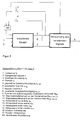
- FIG. 1 shows a block diagram for determining the control signals according to the invention according to the above explanations, wherein the reference numerals used are used consistently in the two figures and are listed again on the drawing sheet of Figure 2 .
- FIG. 1 a so-called transverse acceleration observer is initially provided, which has already been explained with reference to FIG. 2 and the preceding embodiments.
- Whose output is designated by the reference numeral 8 signal for the leading lateral acceleration a q, before .
- On the basis of which is applied to the front axle and on the rear axle of the motor vehicle stabilizer torque 9 to achieve an initially described roll stabilization is determined.
- This so-called total moment can then be suitably distributed to the two axles of the motor vehicle, preferably as a function of the vehicle speed.
- the ratio between the stabilizer target torque of the front axle to be applied by the front axle servomotor (reference numeral 10) and the stabilizer target torque of the rear axle (reference numeral 11) to be applied by the rear axle servomotor is preferably increased with increasing vehicle speed. At low driving speeds, this leads to a high degree of steering willingness of the vehicle and, at high driving speeds, to an understeering, easily manageable vehicle.
- the altitude signals of the individual wheels of the vehicle are taken into account.
- These height signals for the wheels of the front axle (V) or the rear axle (H), designated by the reference numerals 12, 13, 14, 15, respectively left (L) and right (R) are according to the list of reference signs as the signal s VL for the front rider left, s VR for the front right rider height, HL for the rear left rider height, and s HR for the rear right rider.
- This consideration of the altitude signals 12, 13, 14, 15 is carried out according to the invention, in order to at least partially track in the case of an excited by a rough road relative movement of a wheel in the vertical direction associated with this wheel stabilizer half by the associated servo motor said wheel.
- Active stabilizer of the vehicle front axle or the Fzg.-rear axle wherein the term "active stabilizer” is a divided stabilizer as indicated in the preamble of claim 1, ie, a split stabilizer whose stabilizer halves are rotatable by means of a servomotor against each other.
- the altitude signals 12, 13, 14, 15 of the individual Fzg. wheels to be considered in the manner described - in particular as disturbances -.
- the preceding "disturbance factor consideration" for the vehicle rear axle which is also already described above, it is also possible, as explained in FIG . 1 and explained above, to take into account further vehicle sizes, in particular the driving speed
Abstract
Description
Die Erfindung betrifft ein vierrädriges Kraftfahrzeug, insbesondere einen Personenkraftwagen, mit einer Wankstabilisierungs-Vorrichtung in Form geteilter, jeweils einer Fahrzeug-Achse zugeordneter Stabilisatoren, deren Stabilisatorhälften jeweils mittels eines von einer elektronischen Steuereinheit unter Berücksichtigung der Querbeschleunigung und Fahrgeschwindigkeit sowie des Lenkwinkels des Kraftfahrzeugs geeignet angesteuerten elektrischen Stellmotors gegeneinander verdrehbar sind. Zum technischen Umfeld wird insbesondere auf die DE 198 46 275 A1 verwiesen.The invention relates to a four-wheeled motor vehicle, in particular a Passenger car, with a roll stabilization device in the form divided, each associated with a vehicle axle stabilizers whose Stabilizer halves each by means of one of an electronic control unit taking into account the lateral acceleration and driving speed and the steering angle of the motor vehicle suitably controlled electric servomotor are rotated against each other. To the technical In particular, reference is made to DE 198 46 275 A1.
Eine Wankstabilisierung, d.h. eine Reduzierung der rotatorischen Fahrzeugbewegungen um die Fzg.-Längsachse hat eine wesentliche Verbesserung des Fahrverhaltens und des Fahrkomforts zur Folge. Eine praktizierte Möglichkeit, die Wankbewegungen zu verringern, ist die Verwendung von Stabilisatoren. Bei einer gegensinnigen Einfederung der Fzg.-Räder, wie sie bei Kurvenfahrt auftritt, werden die Stabilisatoren tordiert. Auf diese Weise ergibt sich nach der Aufstellung der Kräfte- und Momentenbilanz ein Rückstellmoment, welches der Wankbewegung des Fzg.-Aufbaus entgegenwirkt. Bei einer gleichsinnigen Einfederung beider Räder einer Achse bleibt ein Stabilisator ohne Wirkung. Verursachen Straßenunebenheiten jedoch eine gegensinnige Vertikalbewegung der Räder einer Achse oder regen sie lediglich ein Rad einer Achse an, erhöht der dadurch verdrehte Stabilisator die resultierende Federsteifigkeit am Rad und verstärkt hierdurch eine an sich unerwünschte Kopierbewegung des Fzg.-Aufbaus, die insbesondere bei Geradeausfahrt des Fzg's deutlich spürbar ist. Roll stabilization, i. a reduction of the rotational vehicle movements around the vehicle longitudinal axis has a significant improvement the driving behavior and ride comfort result. One practiced Possibility to reduce the rolling motions is the use of Stabilizers. In an opposing deflection of Fzg. Wheels, as they When cornering occurs, the stabilizers are twisted. In this way arises after the establishment of the balance of forces and moments Return torque, which counteracts the rolling motion of the vehicle body. In the same direction deflection of both wheels of an axle remains a stabilizer without effect. Cause road bumps However, an opposite vertical movement of the wheels of an axle or If you only stimulate one wheel of an axle, it will increase it Stabilizer the resulting spring stiffness on the wheel and thereby amplified a per se undesirable copy movement of Fzg. structure, in particular when driving straight ahead of the Fzg's is clearly noticeable.
Bekannt sind sog. aktive Stabilisatoren in einem Fahrzeug-Fahrwerk, wozu auf die eingangs bereits genannte DE 198 46 275 A1 verwiesen wird. Dabei sind die Stabilisatoren der Vorderachse und der Hinterachse des Kraftfahrzeugs bevorzugt mittig geteilt, wobei die so gebildeten Stabilisatorhälften einer Achse über einen Stellmotor miteinander verbunden sind, der diese "Hälften" gegeneinander tordieren bzw. verdrehen kann. Somit können die Stabilisatoren in einer Kurvenfahrt des Fahrzeugs ein der daraus resultierenden Wankbewegung des Fzg.-Aufbaus entgegenwirkendes Moment in den Fahrzeug-Aufbau einleiten. Günstigstenfalls kann eine Wankbewegung des Fzg.-Aufbaus im Falle einer Kurvenfahrt vollständig unterbunden werden, weshalb diese bekannten Systeme auch als Vorrichtung zur Wankstabilisierung bezeichnet werden.So-called active stabilizers are known in a vehicle chassis, including Reference is made to the aforementioned DE 198 46 275 A1. there are the stabilizers of the front axle and the rear axle of the motor vehicle preferably divided in the middle, with the stabilizer halves thus formed an axis are connected to each other via a servomotor, this "Halves" can twist or twist against each other. Thus, the Stabilizers in a cornering of the vehicle one of the resulting Rolling motion of the vehicle body counteracting moment in the Initiate vehicle setup. At best, a rolling motion of the Fzg. Structure in the event of cornering are completely prevented why these known systems also as a device for roll stabilization be designated.
Auf dem Markt befinden sich bereits Personenkraftwagen mit einer solchen Wankstabilisierungs-Vorrichtung, wobei der genannte Stellmotor ein Hydraulikmotor ist, dessen einander entgegenwirkende Hydraulikkammern durch geeignete Ansteuerung von Hydraulikventilen geeignet befüllt bzw. mit Druck beaufschlagt werden können, um das jeweils gewünschte Moment an die Stabilisatorhälften einer Fzg.-Achse anzulegen. Oben wurde bereits erwähnt, dass insbesondere bei einer Geradeaus-Fahrt des Kraftfahrzeugs eine sog. Kopierbewegung des Fzg.-Aufbaus im Hinblick auf einen guten Fahrkomfort minimiert werden sollte, weshalb in diesen Fällen ein verschwindendes Stabilisatormoment, also eine Entkopplung der Stabilisatorhälften bei einer durch Straßenunebenheiten verursachten einseitigen oder gegensinnigen Radeinfederung angestrebt wird. Diese Anforderung ist nun bei einer hydraulischen Wankstabilisierung systemimmanent ausreichend erfüllt, d.h. aufgrund der physikalischen Eigenschaften eines Hydrauliksystems sind die sog. "aktiven Stabilisatoren" bzw. die einer Achse zugeordneten Stabilisatorhälften für eine Geradeaus-Fahrt des Kraftfahrzeugs prinzipbedingt ausreichend entkoppelt. Passenger cars with such are already on the market Roll stabilization device, said actuator motor Hydraulic motor is its counteracting hydraulic chambers filled by suitable control of hydraulic valves suitable or with Pressure can be applied to the respective desired moment to apply the stabilizer halves of a vehicle axle. Above was already mentions that, in particular in a straight-ahead drive of the motor vehicle a so-called copy movement of the vehicle body with regard to a good Driving comfort should be minimized, which is why in these cases a vanishing Stabilizer torque, ie a decoupling of the stabilizer halves in a unilateral or caused by uneven roads contrary Radeinfederung is sought. This requirement is now Systemimmanent sufficient for a hydraulic roll stabilization fulfilled, i. due to the physical characteristics of a hydraulic system are the so-called "active stabilizers" or assigned to an axis Stabilizer halves for a straight-ahead ride of the motor vehicle in principle sufficiently decoupled.
Neben einem Hydraulikmotor kann als Stellmotor für einen sog. "aktiven Stabilisator" auch ein Elektromotor mit nachgeschaltetem Getriebe verwendet werden, wie dies in der bereits mehrfach genannten DE 198 46 275 A1 beschrieben ist. Ein elektrischer Stellmotor besitzt gegenüber einem hydraulischen Stellmotor diverse Vorteile, die in der genannten Schrift aufgeführt sind, und kann gut direkt von einer elektronischen Steuereinheit angesteuert werden, die - analog den bisherigen hydraulischen Stellmotoren - im Hinblick auf eine gewünschte Wankstabilisierung bei Kurvenfahrt neben dem Fzg.-Lenkwinkel die aktuelle Querbeschleunigung sowie die Fzg.-Fahrgeschwindigkeit berücksichtigt, so wie dies auch in der DE 198 46 275 A1 angegeben ist.In addition to a hydraulic motor can be used as a servomotor for a so-called. "Active Stabilizer "also used an electric motor with downstream gearbox be, as in the already mentioned several times DE 198 46 275 A1 is described. An electric servomotor has opposite one hydraulic servomotor various advantages, mentioned in the document are listed, and may well be directly from an electronic control unit be controlled, the - analogous to the previous hydraulic actuators - In view of a desired roll stabilization when cornering next the vehicle steering angle, the current lateral acceleration and the vehicle driving speed considered, as well as in DE 198 46 275 A1 is specified.
Es hat sich jedoch gezeigt, dass sich mit der Verwendung eines sog. elektromechanischen Aktuators, d.h. eines elektrischen Stellmotors mit nachgeschaltetem Getriebe, in einem aktiven Stabilisator gegenüber einem Hydraulikmotor eine stärkere Kopplung der Stabilisatorhälften ergibt, da diese über das Getriebe und den Elektromotor (des elektromechanischen Aktuators) quasi direkt miteinander verbunden sind. Dies führt dazu, dass sich insbesondere bei einer Geradeaus-Fahrt des Fahrzeugs - hierunter sollen auch Fahrten mit sehr geringem Lenkwinkel fallen, die praktisch keine Wankbewegung des Fzg.-Aufbaus hervorrufen würden - im Falle einer Vertikalbewegung eines Fahrzeug-Rades nur einer Fahrzeugseite (d.h. einem einseitigen Ein- bzw. Ausfedern) oder einer gegensinnigen Vertikalbewegung der Räder einer Achse eine relativ stark spürbare sog. Kopierbewegung des Fzg.-Aufbaus ergibt, was grundsätzlich unerwünscht ist.However, it has been found that with the use of a so-called. electromechanical actuator, i. an electric servomotor with downstream transmission, in an active stabilizer against a Hydraulic motor results in a stronger coupling of the stabilizer halves, since these via the gearbox and the electric motor (the electromechanical Actuator) are virtually directly connected. This leads to especially when driving straight ahead of the vehicle - below should also fall trips with very low steering angle, which is virtually none Rolling motion of the vehicle body would cause - in the case of a Vertical movement of a vehicle wheel only on one side of the vehicle (i.e. a one-sided compression or rebound) or an opposite vertical movement the wheels of an axle a relatively strong so-called. Copy movement of Fzg. Structure results, which is generally undesirable is.
Für ein vierrädriges Kraftfahrzeug nach dem Oberbegriff des Anspruchs 1
eine Abhilfemaßnahme für diese geschilderte Problematik aufzuzeigen, ist
Aufgabe der vorliegenden Erfindung. For a four-wheeled motor vehicle according to the preamble of
Die Lösung dieser Aufgabe ist dadurch gekennzeichnet, dass zusätzlich Höhenstandsignale der einzelnen Räder gegenüber dem Fahrzeug-Aufbau berücksichtigt werden, derart, dass im Falle einer durch eine Straßenunebenheit angeregten Relativbewegung eines Rades in Vertikalrichtung die diesem Rad zugeordnete Stabilisatorhälfte durch den Stellmotor der genannten Rad-Bewegung zumindest teilweise nachgeführt wird. Vorteilhafte Aus- und Weiterbildungen sind Inhalt der Unteransprüche.The solution to this problem is characterized in that in addition Height level signals of the individual wheels compared to the vehicle body be taken in such a way that in the case of a by a road unevenness excited relative movement of a wheel in the vertical direction the assigned to this wheel stabilizer half by the servomotor of mentioned wheel movement is at least partially tracked. advantageous Training and further education are content of the dependent claims.
Es wurde erkannt, dass zur Erzielung eines Fahrkomforts ähnlich dem des hydraulischen Systems, bei welchem der Stellmotor als Hydraulikmotor ausgebildet ist und die Hälften des "aktiven Stabilisators" systembedingt ausreichend voneinander entkoppelt sind, im Falle eines elektromechanischen Aktuators der elektrische Stellmotor die zugeordneten Stabilisatorhälften bspw. auch bei einer Geradeausfahrt (oder dgl.) des Kraftfahrzeugs aktiv verdrehen sollte, wenn eines der Fzg.-Räder ein- oder ausfedert, d.h. eine Relativbewegung gegenüber dem Fzg.-Aufbau in Vertikalrichtung ausführt, oder wenn die Räder einer Achse eine gegensinnige Bewegung in Vertikalrichtung ausführen. Dies tritt nämlich immer dann auf, wenn derartige Relativbewegungen durch Straßenunebenheiten hervorgerufen werden. Zumindest sollte dieses aktive Verdrehen in denjenigen Frequenzbereichen der Radbewegung in Vertikalrichtung durchgeführt werden, in denen der genannte elektromechanische Aktuator (d.h. der elektrische Stellmotor mit nachgeschaltetem Getriebe) die zugeordneten Stabilisatorhälften nicht ausreichend voneinander entkoppelt. Dabei mag es durchaus gewisse Frequenzbereiche in einer Vertikalbewegung eines Rades gegenüber dem Fzg.-Aufbau geben, in denen keine Nachführung der einem Rad zugeordneten Stabilisatorhälfte durch den elektrischen Stellmotor durchgeführt werden muss oder durchgeführt wird.It has been recognized that to achieve ride comfort similar to that of hydraulic system in which the servomotor as a hydraulic motor is formed and the halves of the "active stabilizer" systemic sufficiently decoupled from each other, in the case of an electromechanical Actuators the electric servomotor the associated stabilizer halves For example, even when driving straight ahead (or the like.) Of the motor vehicle active should turn when one of the vehicle wheels springs in or out, i. a Performs relative movement relative to the Fzg. Structure in the vertical direction, or if the wheels of an axle are in opposite directions in the vertical direction To run. This always occurs when such Relative movements caused by uneven roads. At a minimum, this should be active twisting in those frequency ranges the wheel movement are carried out in the vertical direction, in which the called electromechanical actuator (i.e., the electric servomotor with downstream transmission) the associated stabilizer halves not sufficiently decoupled from each other. It certainly likes certain Frequency ranges in a vertical movement of a wheel relative to the Vehicle body type, in which no tracking of a wheel assigned Stabilizer half be performed by the electric servomotor must or is done.
Aus regelungstechnischer Sicht handelt es sich bei den Verdrehungen der Stabilisatoren, die aus den durch Straßenunebenheiten verursachten Vertikalbewegungen der Fzg.-Räder resultieren, um Störgrößen, die ein unerwünschtes Stabilisatormoment erzeugen. Die Erzielung eines guten Störverhaltens ist somit gleichbedeutend mit der Erzielung einer geringen Kopierbewegung des Fahrzeugaufbaus bzw. eines guten Fahrkomforts, nämlich dann wenn die Erzeugung dieses unerwünschten Momentes im wesentlichen vermieden wird. Im Idealfall kann hierzu die jeweils betroffene Stabilisatorhälfte der Vertikalbewegung des zugehörigen Rades nachgeführt werden, um bspw. bzw. insbesondere bei Geradeaus-Fahrt (bzw. im wesentlichen Geradeaus-Fahrt) des Fahrzeugs wie gewünscht einen bevorzugt momentenfreien Stabilisator zu erhalten. Dabei kann durch eine Messung und Verarbeitung der Höhenstände sowie durch eine gezielte Störgrößenaufschaltung eine deutliche Verbesserung des Störverhaltens des geschlossenen elektronischen Regelkreises erzielt werden. Konkret werden aus den sog. Höhenstandsignalen der Fahrzeug-Räder, d.h. den Informationen darüber, in welchen Vertikalpositionen sich die jeweiligen Räder bezogen auf den Fzg.-Aufbau befinden, die Störgrößen, also die daraus resultierenden Verdrehungen der Stabilisatoren, berechnet.From a control engineering point of view, the distortions of the Stabilizers that caused by road bumps Vertical movements of the vehicle wheels result in disturbances that a produce undesirable stabilizer moment. Achieving a good one Störverhaltens is thus synonymous with the achievement of a low Copy movement of the vehicle body or a good ride comfort, namely when the generation of this undesirable moment in the essentially avoided. Ideally, this may be the affected one Stabilizer half tracked the vertical movement of the associated wheel be, for example, or in particular when driving straight ahead (or in the essential straight-ahead drive) of the vehicle as desired preferably to obtain torque-free stabilizer. It can by a Measurement and processing of ride height as well as through a targeted Feedforward control a significant improvement of the disturbance behavior of the closed electronic control circuit can be achieved. Become concrete from the so-called altitude signals of the vehicle wheels, i. the information about which vertical positions the respective wheels are are related to the vehicle body, the disturbances, so the resulting resulting rotations of the stabilizers, calculated.
In anderen Worten ausgedrückt liefert das Höhenstandsignal jedes Fzg.-Rades eine Information darüber, in welcher Position sich dieses Rad aktuell gegenüber dem Fzg.-Aufbau befindet. Insbesondere im Falle einer einseitigen Vertikalbewegung oder einer gegensinnigen Vertikalbewegung der Fzg.-Räder einer Achse trotz oder bei Geradeaus-Fahrt des Fahrzeugs (oder auch bei nur geringen bzw. minimalen Fzg.-Lenkwinkeln) soll nun verhindert werden, dass der Fzg.-Aufbau ausgelöst durch den Stabilisator dieser Bewegung nachfolgt. Erfindungsgemäß wird daher die diesem Rad zugeordnete Stabilisatorhälfte dieser Rad-Vertikalbewegung nachgeführt, und zwar veranlasst durch den Stellmotor, der hierzu geeignet von einer elektronischen Steuereinheit angesteuert wird, die dazu neben anderen Größen die Höhenstandsignale der einzelnen Fahrzeugräder auswertet. Wie bereits erwähnt kann dabei die Ansteuerung des Stellmotors (der Fzg.-Vorderachse bzw. der Fzg.-Hinterachse) so erfolgen, dass die jeweils betroffene Stabilisatorhälfte dem zugehörigen Rad bzw. dessen Vertikalbewegung derart nachgeführt wird, dass durch diesen Stabilisator im wesentlichen kein Moment in den Fzg.-Aufbau eingeleitet wird.In other words, the altitude signal provides each vehicle wheel an information about the position in which this wheel is currently located opposite the vehicle body. Especially in the case of a one-sided Vertical movement or an opposite vertical movement of the Fzg. Wheels an axle despite or while driving straight ahead of the vehicle (or even with only small or minimal vehicle steering angles) should now be prevented be that the Fzg. structure triggered by the stabilizer this Movement follows. Therefore, according to the invention this wheel associated stabilizer half tracked this wheel vertical movement, and caused by the servomotor, suitable for this purpose of a electronic control unit is controlled, in addition to others Sizes evaluates the altitude signals of the individual vehicle wheels. As already mentioned may be the control of the servo motor (the Fzg.-front axle or the vehicle rear axle) so that the respective Affected stabilizer half the associated wheel or its vertical movement is tracked so that by this stabilizer substantially no moment is introduced into the vehicle body.
Selbstverständlich ist die Berücksichtigung von Höhenstandsignalen
einzelner Räder in Fahrwerk-Regelsystemen von Kraftfahrzeugen bereits
bekannt, wozu lediglich beispielhalber auf die US 4,838,574 verwiesen wird,
jedoch gibt es bislang noch keine Berücksichtigung in einem Fahrwerk-Regelsystem
nach dem Oberbegriff des Anspruchs 1 der vorliegenden
Erfindung.Of course, the consideration of altitude signals
single wheels in suspension control systems of motor vehicles already
known, for which reference is made, by way of example only, to US Pat. No. 4,838,574,
however, there is still no consideration in a suspension control system
according to the preamble of
Neben der bislang beschriebenen Messung und (regelungstechnischen) Aufschaltung der einzelnen Höhenstände der Fzg-Räder an der Vorderachse sowie an der Hinterachse auf die zugehörigen elektromechanischen Aktuatoren, d.h. auf den Stellmotor der Vorderachse bzw. der Hinterachse, ist auch ein Konzept möglich, nach welchem die Informationen der Rad-Höhenstandsensoren an der Vorderachse insbesondere in Verbindung mit weiteren gemessenen Fahrzeuggrößen (und hier insbesondere der Fahrzeuggeschwindigkeit, ggf. zusätzlich dem Lenkwinkel) verwendet werden, um an der Hinterachse eine sog. voreilende Information über die sich (in Kürze) ergebenden Höhenstände zu erhalten und somit das Störverhalten an der Hinterachse zu verbessern. In anderen Worten ausgedrückt wird dann aus der Information über die Rad-Höhenstände an der Fahrzeug-Vorderachse unter Berücksichtigung insbesondere der Fahrzeug-Geschwindigkeit eine vorauseilende Information über die jeweiligen Rad-Höhenstände an der Fahrzeug-Hinterachse gewonnen, so dass die Stabilisatorhälften der Hinterachs-Räder im Hinblick hierauf durch den Stellmotor geeignet geführt werden können, und zwar praktisch gleichzeitig mit der dann aufgrund einer Straßenunebenheit oder dgl. ausgeführten Vertikalbewegung des jeweiligen Fzg.-Hinterrades. In addition to the previously described measurement and (control technology) Connection of the individual racks of the Fzg wheels on the front axle as well as at the rear axle on the associated electromechanical Actuators, i. on the servomotor of the front axle or the rear axle, is also a concept possible, according to which the information of the wheel-height sensors at the front axle especially in connection with other measured vehicle sizes (and in particular the Vehicle speed, possibly in addition to the steering angle) used be at the rear axle a so-called leading information about the to obtain (in the near future) resulting rides and thus the Improve disturbing behavior on the rear axle. In other words is then expressed from the information about the wheel rides the vehicle front axle taking into account in particular the Vehicle speed is an anticipatory information about the respective wheel rides gained at the vehicle rear axle, so in that regard, the stabilizer halves of the rear axle wheels pass through the servo motor can be performed suitably, and indeed convenient simultaneously with the then due to a rough road or the like. executed vertical movement of the respective Fzg.-rear wheel.
In vergleichbarer Weise kann im Sinne einer vorteilhaften Weiterbildung der Erfindung auch ein voreilendes Querbeschleunigungs-Signal ermittelt werden. Grundsätzlich kann zwar das bei einer Kurvenfahrt zur Stabilisierung des Fzg.-Aufbaus aufzubringende Stabilisatormoment in Abhängigkeit von der gemessenen Fahrzeugquerbeschleunigung bestimmt werden. Da jedoch zu jedem Zeitpunkt das aktiv gestellte Stabilisator-Moment proportional und entgegengesetzt zum passiven Wankmoment sein soll, müssen die Phasenverzögerungen des Gesamt-Systems kompensiert werden. Diese Phasenverzögerungen setzen sich stets aus einem durch die Trägheit der verwendeten Aktuatorik bestimmten Anteil und einem durch die benötigte Filterung der mit Messrauschen behafteten Eingangssignale bestimmten Anteil zusammen. Hierzu kann nun in der Funktions- bzw. Steuerungslogik mit einem sog. Querbeschleunigungsbeobachter ein der gemessenen Fahrzeugquerbeschleunigung voreilendes Signal berechnet werden, wobei darauf hingewiesen sei, dass ein solches voreilendes Querbeschleunigungssignal in der Fahrwerk-Regelung von Kraftfahrzeugen bereits grundsätzlich bekannt ist, und zwar bspw. aus der DE 44 36 441 C2 bzw. aus der DE 41 26 078 A1.In a similar way, in terms of an advantageous development of Invention also detects a leading lateral acceleration signal become. Basically, while the cornering for stabilization the Fzg. structure to be applied stabilizer torque as a function of the measured vehicle lateral acceleration are determined. However, since at any time the active stabilizer moment proportional and opposite to the passive rolling moment, the Phase delays of the overall system can be compensated. These Phase delays are always a result of the inertia of the used Aktuatorik certain share and one by the required Filtering the erroneous with input noise input signals Share together. This can now be done in the function or control logic with a so-called lateral acceleration observer one of the measured Vehicle lateral acceleration leading signal can be calculated, where It should be noted that such a leading lateral acceleration signal in the suspension control of motor vehicles already basically is known, for example. From DE 44 36 441 C2 and from DE 41 26 078 A1.
Vorteilhaft kann hierzu neben dem gemessenen Querbeschleunigungssignal eine Kombination aus Lenkwinkel und Fahrzeuggeschwindigkeit verwendet werden, da diese Informationen der tatsächlichen Querbeschleunigung zeitlich stets vorauseilen. Problematisch ist hierbei, dass die in einem Beobachter durchgeführte Berechnung der Querbeschleunigung aus dem Lenkwinkel stets von der Güte des zugrundeliegenden Modells abhängt. Aufgrund der notwendigen Vereinfachungen bei der Verwendung numerisch effektiv berechenbarer Modelle sind große Fehler insbesondere im querdynamischen Grenzbereich, gekennzeichnet durch hohe Werte der Querbeschleunigung, nicht auszuschließen. Advantageously, for this purpose, in addition to the measured lateral acceleration signal used a combination of steering angle and vehicle speed because this information is the actual lateral acceleration always ahead of schedule. The problem here is that in one Observer conducted calculation of the lateral acceleration of the Steering angle always depends on the quality of the underlying model. Due to the necessary simplifications when using numerically effectively calculable models are big mistakes especially in lateral dynamic Limit range, characterized by high values of lateral acceleration, not be ruled out.
Bei direkter Anwendung des literaturbekannten Beobachteransatzes mit konstanten Werten der Rückführverstärkungen auf das hier vorliegende Problem der Querbeschleunigungsbestimmung mit Hilfe der genannten Eingangsgrößen ergibt sich der folgend aufgezeigte, funktionseinschränkende Zielkonflikt. Aufgrund des im Vergleich zur Lenkwinkel- und Geschwindigkeitsmessung relativ hohen Rauschanteils der Querbeschleunigungsmessung werden bei der Beobachterauslegung kleine Werte der Rückführverstärkungen angestrebt, um eine möglichst gute Unterdrückung dieses Rauschanteils im resultierenden voreilenden Querbeschleunigungssignal zu erzielen. Andererseits können jedoch nur mit hohen Werten dieser Rückführverstärkungen große Modellfehler bei der beobachterinternen Auswertung des Lenkwinkelsignals vermieden werden.With direct application of the literature observer approach with constant values of the feedback gains on the present here Problem of lateral acceleration determination with the aid of the mentioned Input variables results from the following, function-limiting Conflict. Because of the compared to the steering angle and speed measurement relatively high noise component of the lateral acceleration measurement In the observer interpretation, small values of the feedback gains are sought to suppress as much as possible this Noise component in the resulting leading lateral acceleration signal achieve. On the other hand, however, only with high values of these feedback gains can large model errors in the observer internal evaluation the steering angle signal can be avoided.
Als vorteilhafte Weiterbildung des literaturbekannten Beobachteransatzes wird hier eine geeignete nichtlineare Gestaltung der Rückführungen vorgeschlagen, so dass im Bereich niedriger Querbeschleunigungen kleine Verstärkungswerte verwendet werden, die in Abhängigkeit von der Querbeschleunigung geeignet zunehmen. Hierdurch kann einerseits gewährleistet werden, dass im komfortbestimmenden Bereich um die Geradeausfahrt die benötigte gute Rauschunterdrückung erzielt wird, andererseits können jedoch auch im kaum komfortrelevanten querdynamischen Grenzbereich ausreichend geringe Fehler bei der modellgestützten Querbeschleunigungsberechnung erzielt werden.As an advantageous development of the literature observers approach Here, a suitable non-linear design of the feedback suggested that small in the range of low lateral accelerations Gain values are used, which depend on the lateral acceleration increase suitably. This can be guaranteed on the one hand be that in the comfort-determining area around the straight ahead the required good noise reduction is achieved, on the other hand but also in the hardly comfort-relevant lateral dynamic boundary area sufficiently small errors in the model-based lateral acceleration calculation be achieved.
Bevorzugte Eingangsgrößen des Systems zur Berechnung der Stabilisatorsollmomente sind dann der Lenkwinkel, die Fahrzeuggeschwindigkeit und die Querbeschleunigung. Als zusätzliches Eingangssignal kann sinnvoll noch die Gierrate mitberücksichtigt werden, notwendig ist dieses Signal jedoch für die grundlegende Funktion nicht. Mit dem genannten Querbeschleunigungsbeobachter wird zunächst ein voreilendes Querbeschleunigungssignal ermittelt, und zwar auf Grundlage eines Einspurmodells, das um zwei Zustände erweitert ist, mit deren Hilfe stationäre Genauigkeit des berechneten voreilenden Querbeschleunigungssignals sichergestellt werden kann.Preferred input variables of the system for calculating the stabilizer target torques are then the steering angle, the vehicle speed and the lateral acceleration. As an additional input signal can be useful yet the yaw rate must be taken into account, but this signal is necessary for the basic function is not. With the mentioned lateral acceleration observer initially becomes a leading lateral acceleration signal determined on the basis of a single track model by two States is extended, with the help of which stationary accuracy of the calculated leading transverse acceleration signal can be ensured.
Zur weiteren Erläuterung dieser soeben geschilderten Weiterbildung der
Erfindung wird auf die beigefügte Figur 2 verwiesen. Die Eingänge des
erweiterten Einspur-Modells bilden - wie bereits erwähnt wurde - dabei der
Lenkwinkel δL (Bezugsziffer 1), die Fahrzeuggeschwindigkeit v (Bezugsziffer
2) und die mit einer von der Querbeschleunigung a q (Bezugsziffer 3)
abhängigen Verstärkung multiplizierten Differenzen (a q - a q,Beo) sowie
(ψ ˙-ψ ˙ Beo ). Dabei steht "a q,Beo" für die geschätzte Querbeschleunigung
(Bezugsziffer 5) und "ψ ˙Beo" für die geschätzte Gierrate (Bezugsziffer 6),
während mit "ψ ˙" die Gierrate (Bezugsziffer 4) des Fahrzeugs bezeichnet ist.
Diese genannten Differenzen, multipliziert mit der Verstärkung bilden somit
für das erweiterte Modell eine sog "Nichtlineare Rückführung" (Bezugszeichen
NR). Mit dem Buchstaben "x" bzw. mit der Bezugsziffer 7 ist ein
interner Zustandsvektor bezeichnet, der ebenso wie die geschätzte
Querbeschleunigung a q,Beo eine Ausgangsgröße des erweiterten Einspurmodells
ist. Aus dieser geschätzten Querbeschleunigung a q,Beo, aus der
Differenz (a q - a q,Beo) und aus dem sich ergebenden internen Zustand x wird
das voreilende Querbeschleunigungssignal a q,vor (Bezugsziffer 8) in Echtzeit
durch geeignet gewichtete Summation ermittelt.For further explanation of this just described embodiment of the invention reference is made to the accompanying Figure 2 . The inputs of the extended single-track model are - as already mentioned - while the steering angle δ L (reference numeral 1), the vehicle speed v (reference numeral 2) and multiplied by one of the transverse acceleration a q (reference numeral 3) dependent gain differences (a q - a q, Beo ) and (ψ ˙-ψ ˙ Beo ). Here, "a q, Beo " stands for the estimated lateral acceleration (reference numeral 5) and "ψ ˙ Beo " for the estimated yaw rate (reference numeral 6), while "ψ ˙" denotes the yaw rate (reference numeral 4) of the vehicle. These mentioned differences multiplied by the gain thus form a so-called "non-linear feedback" (reference number NR) for the extended model. The letter "x" or the
Bei der Ausgestaltung der Rückführverstärkungskennlinien in der besagten Nichtlinearen Rückführung NR kann in Erweiterung dieses Ansatzes neben der Abhängigkeit von der Größe der Querbeschleunigung a q eine weitere Abhängigkeit von der Differenz (a q - a q,Beo) vorgesehen werden, wodurch in erwünschter Weise eine weitere Verringerung der resultierenden Modellfehler erzielt werden kann. In eben derselben Weise können bei der abschließenden Berechnung der voreilenden Querbeschleunigung a q,vor durch gewichtete Summation statt konstanter Gewichte geeignete querbeschleunigungsabhängige Nichtlinearitäten vorgesehen werden, durch die eine fahrsituationsabhängig richtige Einstellung des Ausmaßes der Phasenvoreilung erzielt werden kann.In the configuration of the feedback gain characteristics in the said non-linear feedback NR in extension of this approach can in addition to the function of the magnitude of the transverse acceleration a q is a further function of the difference (a q - a q, BeO) are provided, whereby in the desired manner a further Reduction of the resulting model error can be achieved. In just the same way, in the final calculation of the leading lateral acceleration a q, before by weighted summation instead of constant weights suitable lateral acceleration-dependent non-linearities can be provided by which a driving situation-dependent correct adjustment of the extent of the phase advance can be achieved.
In Abhängigkeit von fahrzeugspezifischen Parametern kann dann eine
Umrechnung in ein insgesamt, d.h. an der Vorderachse sowie an der
Hinterachse des Kraftfahrzeugs aufzubringendes Stabilisatormoment
erfolgen, welches in der beigefügten Figur 1 mit der Bezugsziffer 9 bezeichnet
ist. Diese Figur 1 zeigt ein Blockschaltbild zur erfindungsgemäßen
Ermittlung der Stellsignale entsprechend obigen Erläuterungen, wobei die
verwendeten Bezugsziffern in den beiden Figuren einheitlich verwendet sind
und auf dem Zeichnungsblatt der Figur 2 nochmals aufgelistet sind.Depending on vehicle-specific parameters, a conversion to a total, ie applied to the front axle and on the rear axle of the motor vehicle stabilizer torque can then take place, which is designated in the accompanying Figure 1 by the
Nun auf Figur 1 Bezug nehmend ist also zunächst ein sog. Querbeschleunigungsbeobachter
vorgesehen, der anhand von Figur 2 und den vorangegangenen
Ausführungen bereits erläutert wurde. Dessen Ausgangsgröße ist
ein mit der Bezugsziffer 8 bezeichnetes Signal für die voreilende Querbeschleunigung
a q,vor. Anhand derer wird das an der Vorderachse sowie an der
Hinterachse des Kraftfahrzeugs aufzubringende Stabilisatormoment 9 zur
Erzielung einer eingangs geschilderten Wankstabilisierung bestimmt. Dieses
sog. Gesamtmoment kann dann anschließend auf die beiden Achsen des
Kraftfahrzeugs geeignet verteilt werden, und zwar bevorzugt in Abhängigkeit
von der Fahrzeuggeschwindigkeit. Bevorzugt wird dabei das Verhältnis
zwischen dem vom Vorderachs-Stellmotor aufzubringenden Stabilisator-Sollmoment
der Vorderachse (Bezugsziffer 10) und dem vom Hinterachs-Stellmotor
aufzubringenden Stabilisator-Sollmoment der Hinterachse
(Bezugsziffer 11) mit steigender Fzg.-Fahr-Geschwindigkeit vergrößert. Dies
führt bei geringen Fahrgeschwindigkeiten zu einer hohen Lenkwilligkeit des
Fahrzeugs und bei hohen Fahrgeschwindigkeiten zu einem untersteuernden,
gut beherrschbaren Fahrzeug. Referring now to FIG. 1 , a so-called transverse acceleration observer is initially provided, which has already been explained with reference to FIG. 2 and the preceding embodiments. Whose output is designated by the
Wie weiter oben ausführlich erläutert wurde, werden auch noch die Höhenstandsignale
der einzelnen Räder des Fahrzeugs berücksichtigt. Diese mit
den Bezugsziffern 12, 13, 14, 15 bezeichneten Höhenstandsignale für die
Räder der Vorderachse (V) bzw. der Hinterachse (H) jeweils links (L) bzw.
rechts (R) sind laut Bezugszeichenliste als Signal sVL für den Höhenstand
vorne links, sVR für den Höhenstand vorne rechts, sHL für den Höhenstand
hinten links, und sHR für den Höhenstand hinten rechts bezeichnet. Diese
Berücksichtigung der Höhenstandsignale 12, 13, 14, 15 erfolgt erfindungsgemäß,
um im Falle einer durch eine Straßenunebenheit angeregten
Relativbewegung eines Rades in Vertikalrichtung die diesem Rad zugeordnete
Stabilisatorhälfte durch den zugehörigen Stellmotor der genannten Rad-Bewegung
zumindest teilweise nachführen zu können. Dementsprechend
erfolgt also die Berechnung der Stellsignale für den sog. aktiven Stabilisator
der Fzg-Vorderachse bzw. der Fzg.-Hinterachse, wobei mit dem Begriff
"aktiver Stabilisator" ein geteilter Stabilisator wie im Oberbegriff des
Anspruchs 1 angegeben bezeichnet ist, d.h. ein geteilter Stabilisator, dessen
Stabilisatorhälften mittels eines Stellmotors gegeneinander verdrehbar sind.As explained in detail above, also the altitude signals of the individual wheels of the vehicle are taken into account. These height signals for the wheels of the front axle (V) or the rear axle (H), designated by the
In die besagte Berechnung der Stellsignale für die aktiven Stabilisatoren
bzw. deren Stellmotore gehen also nicht nur die an der Fzg.-Vorderachse
bzw. an der Fzg.-Hinterachse aufzubringenden Momente für die Wankstabilisierung
(als Stabilisatormoment 10 bzw. 11 bezeichnet) ein, sondern
erfindungsgemäß auch die Höhenstandsignale 12, 13, 14, 15 der einzelnen
Fzg.-Räder, um in der beschriebenen Weise - insbesondere als
Störgrößen - berücksichtigt zu werden. Im Hinblick auf die weiter oben ebenfalls bereits
geschilderte voreilende "Störgrößen-Berücksichtigung" für die Fzg.-Hinterachse
können dabei - wie in Fig.1 angegeben und weiter oben
erläutert - noch weitere Fzg.-Größen, insbesondere die Fahrgeschwindigkeit,
Berücksichtigung finden, wobei noch darauf hingewiesen sei, dass durchaus
eine Vielzahl von Details auch abweichend von obigen Erläuterungen
gestaltet sein kann, ohne den Inhalt der Patentansprüche zu verlassen.In the said calculation of the control signals for the active stabilizers or their servo motors so go not only the applied to the vehicle front axle or on the vehicle rear axle torque for roll stabilization (referred to as
Claims (6)
dadurch gekennzeichnet, dass zusätzlich Höhenstandsignale der einzelnen Räder gegenüber dem Fahrzeug-Aufbau berücksichtigt werden, derart, dass im Falle einer durch Straßenunebenheiten angeregten Relativbewegung eines Rades in Vertikalrichtung die diesem Rad zugeordnete Stabilisatorhälfte durch den Stellmotor der genannten Rad-Bewegung zumindest teilweise nachgeführt wird.Four-wheeled motor vehicle, especially passenger cars, with a roll stabilization device in the form of divided, one vehicle axle associated stabilizers whose stabilizer halves are each rotated by means of one of an electronic control unit taking into account the lateral acceleration and driving speed and the steering angle of the motor vehicle suitably controlled electric servomotor against each other .
characterized in that in addition height level signals of the individual wheels are taken into account with respect to the vehicle structure, such that in the case of an excited by uneven roads relative movement of a wheel in the vertical direction associated with this wheel stabilizer half is at least partially tracked by the servo motor of said wheel movement.
dadurch gekennzeichnet, dass die Stabilisatorhälfte derart nachgeführt wird, dass durch diese im wesentlichen kein durch eine Straßenunebenheit verursachtes Moment in die zugehörige Radaufhängung eingeleitet wird.Motor vehicle according to claim 1,
characterized in that the stabilizer half is tracked such that it is introduced by this substantially no caused by a road irregularity moment in the associated suspension.
dadurch gekennzeichnet, dass die Nachführung der Stabilisatorhälfte nur in bestimmten Frequenzbereichen der Radbewegung in Vertikalrichtung durchgeführt wird. Motor vehicle according to claim 1 or 2,
characterized in that the tracking of the stabilizer half is performed only in certain frequency ranges of the wheel movement in the vertical direction.
dadurch gekennzeichnet, dass aus der Information über die Rad-Höhenstände an der Fahrzeug-Vorderachse unter Berücksichtigung insbesondere der Fahrzeug-Geschwindigkeit eine voreilende Information über die jeweiligen Rad-Höhenstände an der Fahrzeug-Hinterachse gewonnen wird und die Stabilisatorhälften der Hinterachs-Räder im Hinblick hierauf durch den Stellmotor geeignet geführt werden.Motor vehicle according to one of the preceding claims,
characterized in that from the information about the wheel ride heights on the vehicle front axle taking into account in particular the vehicle speed, a leading information about the respective wheel ride heights is obtained on the vehicle rear axle and the stabilizer halves of the rear wheels with respect thereto be performed suitably by the servomotor.
dadurch gekennzeichnet, dass aus einem die aktuelle Querbeschleunigung wiedergebenden Signal unter Berücksichtigung des Lenkwinkels und der Fahrzeug-Geschwindigkeit und der Gierrate ein voreilendes Querbeschleunigungs-Signal ermittelt wird.Motor vehicle according to one of the preceding claims,
characterized in that a leading transverse acceleration signal is determined from a signal representing the current lateral acceleration taking into account the steering angle and the vehicle speed and the yaw rate.
dadurch gekennzeichnet, dass aus dem voreilenden Querbeschleunigungs-Signal ein für die Vorderachse und die Hinterachse des Fahrzeugs benötigtes Gesamtmoment für eine Wankstabilisierung ermittelt wird, wobei die Aufteilung dieses Gesamtmoments auf den dem Vorderachs-Stabilisator zugeordneten Stellmotor und den dem Hinterachs-Stabilisator zugeordneten Stellmotor unter Berücksichtigung der aktuellen Fahrzeug-Geschwindigkeit erfolgt.Motor vehicle according to claim 5,
characterized in that a required for the front axle and the rear axle of the vehicle total torque for roll stabilization is determined from the leading lateral acceleration signal, the division of this total torque on the front axle stabilizer associated actuator and the rear axle stabilizer associated actuator under consideration the current vehicle speed is done.
Applications Claiming Priority (2)
| Application Number | Priority Date | Filing Date | Title |
|---|---|---|---|
| DE2002121718 DE10221718A1 (en) | 2002-05-16 | 2002-05-16 | Motor vehicle, in particular passenger cars, with a roll stabilization device |
| DE10221718 | 2002-05-16 |
Publications (3)
| Publication Number | Publication Date |
|---|---|
| EP1362720A2 true EP1362720A2 (en) | 2003-11-19 |
| EP1362720A3 EP1362720A3 (en) | 2005-03-23 |
| EP1362720B1 EP1362720B1 (en) | 2006-06-21 |
Family
ID=29265317
Family Applications (1)
| Application Number | Title | Priority Date | Filing Date |
|---|---|---|---|
| EP20030008206 Expired - Lifetime EP1362720B1 (en) | 2002-05-16 | 2003-04-08 | Motor vehicle, especially passenger car, with a device for roll-stabilization |
Country Status (2)
| Country | Link |
|---|---|
| EP (1) | EP1362720B1 (en) |
| DE (2) | DE10221718A1 (en) |
Cited By (12)
| Publication number | Priority date | Publication date | Assignee | Title |
|---|---|---|---|---|
| WO2006135072A1 (en) * | 2005-06-16 | 2006-12-21 | Toyota Jidosha Kabushiki Kaisha | Vehicle stabilizer system |
| WO2006134954A3 (en) * | 2005-06-16 | 2007-04-19 | Toyota Motor Co Ltd | Stabilizer system of vehicle |
| FR2912083A1 (en) * | 2007-02-01 | 2008-08-08 | Renault Sas | Active anti-rolling system control method for vehicle, involves determining yaw estimated speed from non linear model with two wheels to determine anti-rolling torque set point based on difference between estimated and desired yaw speed |
| EP2397348A1 (en) * | 2009-02-16 | 2011-12-21 | Toyota Jidosha Kabushiki Kaisha | Stabilizer control device for vehicle |
| DE102011080055A1 (en) | 2011-07-28 | 2013-01-31 | Zf Friedrichshafen Ag | Stabilizer arrangement for motor car, has stabilizer halves implementing relative rotational movement to each other, and triangular spring/damper element integrated in arrangement for representation of progressive stabilizer curve |
| DE102015122043A1 (en) | 2015-12-17 | 2017-06-22 | Dr. Ing. H.C. F. Porsche Aktiengesellschaft | Situation-dependent roll stabilization |
| WO2018114173A1 (en) * | 2016-12-22 | 2018-06-28 | Zf Friedrichshafen Ag | Safety function and control device for monitoring and controlling of roll stabilizers |
| WO2018219564A1 (en) * | 2017-05-31 | 2018-12-06 | Zf Friedrichshafen Ag | Device and method for roll stabilization |
| DE102018217992A1 (en) | 2018-10-22 | 2020-04-23 | Zf Friedrichshafen Ag | Method for operating an actuator of an active chassis device and active chassis device |
| US11511593B2 (en) * | 2019-09-03 | 2022-11-29 | Zf Friedrichshafen Ag | Method of operating an adjustable roll stabilizer |
| US11560035B2 (en) | 2019-09-03 | 2023-01-24 | Zf Friedrichshafen Ag | Method of operating an adjustable roll stabilizer |
| US11618297B2 (en) | 2019-09-03 | 2023-04-04 | Zf Friedrichshafen Ag | Method of operating an adjustable roll stabilizer |
Families Citing this family (9)
| Publication number | Priority date | Publication date | Assignee | Title |
|---|---|---|---|---|
| DE102006055733A1 (en) * | 2006-11-25 | 2008-05-29 | Zf Friedrichshafen Ag | stabilizer assembly |
| DE102007018194B4 (en) | 2007-04-18 | 2016-10-13 | Bayerische Motoren Werke Aktiengesellschaft | Two-lane motor vehicle with a roll stabilization device |
| DE102008000240A1 (en) * | 2008-02-06 | 2009-08-13 | Zf Friedrichshafen Ag | Method for preventing copying of one side deflecting movement on other axial side caused by electromechanical stabilizers, involves controlling electric motor of electromechanical stabilizer |
| DE102010051807A1 (en) * | 2010-11-18 | 2012-05-24 | Magna Powertrain Ag & Co. Kg | Roll stabilization device for use in motor car for e.g. stabilizing car against rolling movements during driving on curves, has control device operating actuator so that torque transmission between two stabilizer halves is counteracted |
| DE102016104944A1 (en) * | 2016-03-17 | 2017-09-21 | Dr. Ing. H.C. F. Porsche Aktiengesellschaft | Method for carrying out roll stabilization of a vehicle |
| DE102016225351B4 (en) | 2016-12-16 | 2021-11-04 | Volkswagen Aktiengesellschaft | Method for determining an interaction between a wheel of a motor vehicle and a roadway, as well as a control device and a motor vehicle |
| DE102017209142A1 (en) | 2017-05-31 | 2018-12-06 | Zf Friedrichshafen Ag | Stabilizer arrangement for motor vehicles |
| DE102018211209A1 (en) | 2018-07-06 | 2020-01-09 | Bayerische Motoren Werke Aktiengesellschaft | Operating method for a split stabilizer in the chassis of a two-track vehicle |
| DE102019213273B4 (en) * | 2019-09-03 | 2022-03-17 | Zf Friedrichshafen Ag | System for roll stabilization of a motor vehicle |
Citations (4)
| Publication number | Priority date | Publication date | Assignee | Title |
|---|---|---|---|---|
| US4838574A (en) | 1987-12-14 | 1989-06-13 | Ford Motor Company | Hybrid suspension position and body velocity sensing system for automotive suspension control system |
| DE4126078A1 (en) | 1991-08-07 | 1993-02-11 | Fichtel & Sachs Ag | Control system for active suspension on vehicle - computes transverse acceleration from corrected relationship incorporating wheel drift and other factors, for control of shock absorber |
| DE4436441C2 (en) | 1993-10-15 | 1997-09-11 | Fichtel & Sachs Ag | Method for controlling a motor vehicle chassis |
| DE19846275A1 (en) | 1998-06-25 | 1999-12-30 | Bosch Gmbh Robert | System for roll-stabilization of vehicles, especially cars |
Family Cites Families (4)
| Publication number | Priority date | Publication date | Assignee | Title |
|---|---|---|---|---|
| IT1245804B (en) * | 1991-05-06 | 1994-10-18 | Fiat Auto Spa | SYSTEM FOR THE CONTROL OF THE LOAD OF AN ANTI-ROLL STABILIZER BAR ASSOCIATED WITH A SUSPENSION WITH INDEPENDENT WHEELS OF A VEHICLE. |
| DE4136262C2 (en) * | 1991-11-04 | 2000-10-26 | Mannesmann Sachs Ag | Chassis of a motor vehicle |
| GB9927295D0 (en) * | 1999-11-19 | 2000-01-12 | Rover Group | Vehicle suspensions |
| DE10012131B4 (en) * | 2000-03-13 | 2010-08-19 | Robert Bosch Gmbh | Suspension control system for vehicles |
-
2002
- 2002-05-16 DE DE2002121718 patent/DE10221718A1/en not_active Withdrawn
-
2003
- 2003-04-08 DE DE50303903T patent/DE50303903D1/en not_active Expired - Lifetime
- 2003-04-08 EP EP20030008206 patent/EP1362720B1/en not_active Expired - Lifetime
Patent Citations (4)
| Publication number | Priority date | Publication date | Assignee | Title |
|---|---|---|---|---|
| US4838574A (en) | 1987-12-14 | 1989-06-13 | Ford Motor Company | Hybrid suspension position and body velocity sensing system for automotive suspension control system |
| DE4126078A1 (en) | 1991-08-07 | 1993-02-11 | Fichtel & Sachs Ag | Control system for active suspension on vehicle - computes transverse acceleration from corrected relationship incorporating wheel drift and other factors, for control of shock absorber |
| DE4436441C2 (en) | 1993-10-15 | 1997-09-11 | Fichtel & Sachs Ag | Method for controlling a motor vehicle chassis |
| DE19846275A1 (en) | 1998-06-25 | 1999-12-30 | Bosch Gmbh Robert | System for roll-stabilization of vehicles, especially cars |
Cited By (19)
| Publication number | Priority date | Publication date | Assignee | Title |
|---|---|---|---|---|
| WO2006135072A1 (en) * | 2005-06-16 | 2006-12-21 | Toyota Jidosha Kabushiki Kaisha | Vehicle stabilizer system |
| WO2006134954A3 (en) * | 2005-06-16 | 2007-04-19 | Toyota Motor Co Ltd | Stabilizer system of vehicle |
| CN101189138B (en) * | 2005-06-16 | 2010-05-19 | 丰田自动车株式会社 | Vehicle stabilizer system |
| CN101198484B (en) * | 2005-06-16 | 2010-06-23 | 丰田自动车株式会社 | Stabilizer system of vehicle |
| US7871083B2 (en) | 2005-06-16 | 2011-01-18 | Toyota Jidosha Kabushiki Kaisha | Stabilizer system of vehicle |
| US8027765B2 (en) | 2005-06-16 | 2011-09-27 | Toyota Jidosha Kabushiki Kaisha | Vehicle stabilizer system |
| FR2912083A1 (en) * | 2007-02-01 | 2008-08-08 | Renault Sas | Active anti-rolling system control method for vehicle, involves determining yaw estimated speed from non linear model with two wheels to determine anti-rolling torque set point based on difference between estimated and desired yaw speed |
| WO2008107613A1 (en) * | 2007-02-01 | 2008-09-12 | Renault S.A.S. | System and method for open loop control of an active anti-roll system by characterizing the yaw rate of a vehicle based on a nonlinear two-wheel model |
| EP2397348A1 (en) * | 2009-02-16 | 2011-12-21 | Toyota Jidosha Kabushiki Kaisha | Stabilizer control device for vehicle |
| EP2397348A4 (en) * | 2009-02-16 | 2013-10-23 | Toyota Motor Co Ltd | Stabilizer control device for vehicle |
| DE102011080055A1 (en) | 2011-07-28 | 2013-01-31 | Zf Friedrichshafen Ag | Stabilizer arrangement for motor car, has stabilizer halves implementing relative rotational movement to each other, and triangular spring/damper element integrated in arrangement for representation of progressive stabilizer curve |
| DE102015122043A1 (en) | 2015-12-17 | 2017-06-22 | Dr. Ing. H.C. F. Porsche Aktiengesellschaft | Situation-dependent roll stabilization |
| WO2018114173A1 (en) * | 2016-12-22 | 2018-06-28 | Zf Friedrichshafen Ag | Safety function and control device for monitoring and controlling of roll stabilizers |
| WO2018219564A1 (en) * | 2017-05-31 | 2018-12-06 | Zf Friedrichshafen Ag | Device and method for roll stabilization |
| DE102018217992A1 (en) | 2018-10-22 | 2020-04-23 | Zf Friedrichshafen Ag | Method for operating an actuator of an active chassis device and active chassis device |
| WO2020083569A1 (en) | 2018-10-22 | 2020-04-30 | Zf Friedrichshafen Ag | Method for operating an actuator of an active chassis device and active chassis device |
| US11511593B2 (en) * | 2019-09-03 | 2022-11-29 | Zf Friedrichshafen Ag | Method of operating an adjustable roll stabilizer |
| US11560035B2 (en) | 2019-09-03 | 2023-01-24 | Zf Friedrichshafen Ag | Method of operating an adjustable roll stabilizer |
| US11618297B2 (en) | 2019-09-03 | 2023-04-04 | Zf Friedrichshafen Ag | Method of operating an adjustable roll stabilizer |
Also Published As
| Publication number | Publication date |
|---|---|
| DE50303903D1 (en) | 2006-08-03 |
| EP1362720A3 (en) | 2005-03-23 |
| DE10221718A1 (en) | 2003-11-27 |
| EP1362720B1 (en) | 2006-06-21 |
Similar Documents
| Publication | Publication Date | Title |
|---|---|---|
| EP1362720B1 (en) | Motor vehicle, especially passenger car, with a device for roll-stabilization | |
| EP2590850B1 (en) | Method to determine a rack force for the steering system of a vehicle | |
| EP0348817B1 (en) | Device to check rolling of a vehicle | |
| DE112009005462B4 (en) | Lenkungsssteuervorrichtung | |
| EP1890920B1 (en) | Vehicle dynamics control adapted to driving state and based on steering interventions | |
| DE102006047220B4 (en) | A vehicle having a combined roll angle and roll stiffness front-to-back split ratio control and a control method therefor | |
| DE102005037479B4 (en) | Vehicle dynamics control system for a two-lane motor vehicle | |
| DE102008053008A1 (en) | Method and system for influencing the movement of a controllable in his movements vehicle structure of a motor vehicle and vehicle | |
| DE102015212229B4 (en) | Method for steering a vehicle, control for a motor vehicle and vehicle with front-axle and rear-axle steering | |
| DE19836674C1 (en) | Method for influencing the roll behavior of motor vehicles | |
| EP0989049B1 (en) | Tractor-trailer combination and method for its stabilisation | |
| DE102006052698A1 (en) | Method and device for stabilizing a motor vehicle | |
| EP2288532B1 (en) | Device and method for influencing the transverse dynamics of a vehicle | |
| DE102011007263B4 (en) | Method for creating a control function for a pre-coupling controlled active steering of a motor vehicle and control method and control system for a motor vehicle | |
| DE112018006928T5 (en) | Steering control device and steering device | |
| EP1588927B1 (en) | Automotive vehicle with active rear wheel steering | |
| DE10330895A1 (en) | Control of straight-line interference of a motor vehicle | |
| DE102016005966A1 (en) | Method for improving the yawing behavior of a motor vehicle | |
| DE102008052991A1 (en) | Method for production of signals for influencing movement of vehicle body of motor vehicle controllable or adjustable in its path of motion, involves determining sensory movement of vehicle body | |
| DE102021131739B3 (en) | Method and control circuit for controlling an active rear-axle steering system of a motor vehicle during steering when driving straight ahead, and motor vehicle with the control circuit | |
| EP2052884A2 (en) | Method and system for affecting the movement of a vehicle structure on a powered vehicle and vehicle controlled or regulated by its movement processes | |
| DE102012217672A1 (en) | Method for adjusting yaw damping on two-lane two-axle motor vehicle, involves creating single-track model or model diagram for explaining steady state and transient lateral dynamics of double-track vehicle by accessing model parameters | |
| DE102021205561A1 (en) | Method and system for controlling a vehicle | |
| WO2005000650A1 (en) | Stabilizing device, vehicle equipped therewith, and stabilizing method | |
| WO2005102745A1 (en) | Method for driving stability control for a vehicle |
Legal Events
| Date | Code | Title | Description |
|---|---|---|---|
| PUAI | Public reference made under article 153(3) epc to a published international application that has entered the european phase |
Free format text: ORIGINAL CODE: 0009012 |
|
| AK | Designated contracting states |
Kind code of ref document: A2 Designated state(s): AT BE BG CH CY CZ DE DK EE ES FI FR GB GR HU IE IT LI LU MC NL PT RO SE SI SK TR |
|
| AX | Request for extension of the european patent |
Extension state: AL LT LV MK |
|
| PUAL | Search report despatched |
Free format text: ORIGINAL CODE: 0009013 |
|
| AK | Designated contracting states |
Kind code of ref document: A3 Designated state(s): AT BE BG CH CY CZ DE DK EE ES FI FR GB GR HU IE IT LI LU MC NL PT RO SE SI SK TR |
|
| AX | Request for extension of the european patent |
Extension state: AL LT LV MK |
|
| 17P | Request for examination filed |
Effective date: 20050405 |
|
| GRAP | Despatch of communication of intention to grant a patent |
Free format text: ORIGINAL CODE: EPIDOSNIGR1 |
|
| AKX | Designation fees paid |
Designated state(s): DE FR GB IT |
|
| GRAS | Grant fee paid |
Free format text: ORIGINAL CODE: EPIDOSNIGR3 |
|
| GRAA | (expected) grant |
Free format text: ORIGINAL CODE: 0009210 |
|
| AK | Designated contracting states |
Kind code of ref document: B1 Designated state(s): DE FR GB IT |
|
| PG25 | Lapsed in a contracting state [announced via postgrant information from national office to epo] |
Ref country code: IT Free format text: LAPSE BECAUSE OF FAILURE TO SUBMIT A TRANSLATION OF THE DESCRIPTION OR TO PAY THE FEE WITHIN THE PRESCRIBED TIME-LIMIT;WARNING: LAPSES OF ITALIAN PATENTS WITH EFFECTIVE DATE BEFORE 2007 MAY HAVE OCCURRED AT ANY TIME BEFORE 2007. THE CORRECT EFFECTIVE DATE MAY BE DIFFERENT FROM THE ONE RECORDED. Effective date: 20060621 |
|
| REG | Reference to a national code |
Ref country code: GB Ref legal event code: FG4D Free format text: NOT ENGLISH |
|
| GBT | Gb: translation of ep patent filed (gb section 77(6)(a)/1977) |
Effective date: 20060712 |
|
| REF | Corresponds to: |
Ref document number: 50303903 Country of ref document: DE Date of ref document: 20060803 Kind code of ref document: P |
|
| ET | Fr: translation filed | ||
| PLBE | No opposition filed within time limit |
Free format text: ORIGINAL CODE: 0009261 |
|
| STAA | Information on the status of an ep patent application or granted ep patent |
Free format text: STATUS: NO OPPOSITION FILED WITHIN TIME LIMIT |
|
| 26N | No opposition filed |
Effective date: 20070322 |
|
| REG | Reference to a national code |
Ref country code: FR Ref legal event code: PLFP Year of fee payment: 14 |
|
| REG | Reference to a national code |
Ref country code: FR Ref legal event code: PLFP Year of fee payment: 15 |
|
| REG | Reference to a national code |
Ref country code: FR Ref legal event code: PLFP Year of fee payment: 16 |
|
| PGFP | Annual fee paid to national office [announced via postgrant information from national office to epo] |
Ref country code: IT Payment date: 20220429 Year of fee payment: 20 Ref country code: GB Payment date: 20220425 Year of fee payment: 20 Ref country code: FR Payment date: 20220420 Year of fee payment: 20 Ref country code: DE Payment date: 20220421 Year of fee payment: 20 |
|
| REG | Reference to a national code |
Ref country code: DE Ref legal event code: R071 Ref document number: 50303903 Country of ref document: DE |
|
| REG | Reference to a national code |
Ref country code: GB Ref legal event code: PE20 Expiry date: 20230407 |
|
| P01 | Opt-out of the competence of the unified patent court (upc) registered |
Effective date: 20230427 |
|
| PG25 | Lapsed in a contracting state [announced via postgrant information from national office to epo] |
Ref country code: GB Free format text: LAPSE BECAUSE OF EXPIRATION OF PROTECTION Effective date: 20230407 |