EP1362685B2 - Hermetically sealed container with frangible web and locking lugs and method and apparatus for making same - Google Patents
Hermetically sealed container with frangible web and locking lugs and method and apparatus for making same Download PDFInfo
- Publication number
- EP1362685B2 EP1362685B2 EP03012888A EP03012888A EP1362685B2 EP 1362685 B2 EP1362685 B2 EP 1362685B2 EP 03012888 A EP03012888 A EP 03012888A EP 03012888 A EP03012888 A EP 03012888A EP 1362685 B2 EP1362685 B2 EP 1362685B2
- Authority
- EP
- European Patent Office
- Prior art keywords
- container
- main
- parison
- assembly
- seal mold
- Prior art date
- Legal status (The legal status is an assumption and is not a legal conclusion. Google has not performed a legal analysis and makes no representation as to the accuracy of the status listed.)
- Expired - Lifetime
Links
- 238000000034 method Methods 0.000 title claims description 24
- 238000000465 moulding Methods 0.000 claims description 38
- 238000011049 filling Methods 0.000 claims description 30
- 238000007664 blowing Methods 0.000 claims description 26
- 230000002093 peripheral effect Effects 0.000 claims description 14
- 210000005069 ears Anatomy 0.000 claims description 7
- 238000004519 manufacturing process Methods 0.000 claims description 4
- 238000007599 discharging Methods 0.000 claims description 2
- 238000007789 sealing Methods 0.000 description 11
- 230000000712 assembly Effects 0.000 description 9
- 238000000429 assembly Methods 0.000 description 9
- 238000010586 diagram Methods 0.000 description 9
- 238000004891 communication Methods 0.000 description 5
- 239000012815 thermoplastic material Substances 0.000 description 4
- 239000002131 composite material Substances 0.000 description 2
- 230000007246 mechanism Effects 0.000 description 2
- -1 polyethylene Polymers 0.000 description 2
- 229920001169 thermoplastic Polymers 0.000 description 2
- 239000004416 thermosoftening plastic Substances 0.000 description 2
- 239000004698 Polyethylene Substances 0.000 description 1
- 239000004743 Polypropylene Substances 0.000 description 1
- 230000009471 action Effects 0.000 description 1
- 230000009977 dual effect Effects 0.000 description 1
- 238000001125 extrusion Methods 0.000 description 1
- 238000001990 intravenous administration Methods 0.000 description 1
- 239000007788 liquid Substances 0.000 description 1
- 239000000463 material Substances 0.000 description 1
- 239000012778 molding material Substances 0.000 description 1
- 229920000573 polyethylene Polymers 0.000 description 1
- 229920001155 polypropylene Polymers 0.000 description 1
- 238000003825 pressing Methods 0.000 description 1
- 230000009467 reduction Effects 0.000 description 1
- 238000009757 thermoplastic moulding Methods 0.000 description 1
- 238000013022 venting Methods 0.000 description 1
Images


Classifications
-
- B—PERFORMING OPERATIONS; TRANSPORTING
- B65—CONVEYING; PACKING; STORING; HANDLING THIN OR FILAMENTARY MATERIAL
- B65D—CONTAINERS FOR STORAGE OR TRANSPORT OF ARTICLES OR MATERIALS, e.g. BAGS, BARRELS, BOTTLES, BOXES, CANS, CARTONS, CRATES, DRUMS, JARS, TANKS, HOPPERS, FORWARDING CONTAINERS; ACCESSORIES, CLOSURES, OR FITTINGS THEREFOR; PACKAGING ELEMENTS; PACKAGES
- B65D23/00—Details of bottles or jars not otherwise provided for
- B65D23/003—Suspension means
-
- B—PERFORMING OPERATIONS; TRANSPORTING
- B65—CONVEYING; PACKING; STORING; HANDLING THIN OR FILAMENTARY MATERIAL
- B65B—MACHINES, APPARATUS OR DEVICES FOR, OR METHODS OF, PACKAGING ARTICLES OR MATERIALS; UNPACKING
- B65B3/00—Packaging plastic material, semiliquids, liquids or mixed solids and liquids, in individual containers or receptacles, e.g. bags, sacks, boxes, cartons, cans, or jars
- B65B3/02—Machines characterised by the incorporation of means for making the containers or receptacles
- B65B3/022—Making containers by moulding of a thermoplastic material
-
- B—PERFORMING OPERATIONS; TRANSPORTING
- B65—CONVEYING; PACKING; STORING; HANDLING THIN OR FILAMENTARY MATERIAL
- B65D—CONTAINERS FOR STORAGE OR TRANSPORT OF ARTICLES OR MATERIALS, e.g. BAGS, BARRELS, BOTTLES, BOXES, CANS, CARTONS, CRATES, DRUMS, JARS, TANKS, HOPPERS, FORWARDING CONTAINERS; ACCESSORIES, CLOSURES, OR FITTINGS THEREFOR; PACKAGING ELEMENTS; PACKAGES
- B65D1/00—Rigid or semi-rigid containers having bodies formed in one piece, e.g. by casting metallic material, by moulding plastics, by blowing vitreous material, by throwing ceramic material, by moulding pulped fibrous material or by deep-drawing operations performed on sheet material
- B65D1/02—Bottles or similar containers with necks or like restricted apertures, designed for pouring contents
- B65D1/0223—Bottles or similar containers with necks or like restricted apertures, designed for pouring contents characterised by shape
- B65D1/023—Neck construction
- B65D1/0238—Integral frangible closures
-
- B—PERFORMING OPERATIONS; TRANSPORTING
- B29—WORKING OF PLASTICS; WORKING OF SUBSTANCES IN A PLASTIC STATE IN GENERAL
- B29C—SHAPING OR JOINING OF PLASTICS; SHAPING OF MATERIAL IN A PLASTIC STATE, NOT OTHERWISE PROVIDED FOR; AFTER-TREATMENT OF THE SHAPED PRODUCTS, e.g. REPAIRING
- B29C2949/00—Indexing scheme relating to blow-moulding
- B29C2949/07—Preforms or parisons characterised by their configuration
- B29C2949/0715—Preforms or parisons characterised by their configuration the preform having one end closed
-
- B—PERFORMING OPERATIONS; TRANSPORTING
- B29—WORKING OF PLASTICS; WORKING OF SUBSTANCES IN A PLASTIC STATE IN GENERAL
- B29C—SHAPING OR JOINING OF PLASTICS; SHAPING OF MATERIAL IN A PLASTIC STATE, NOT OTHERWISE PROVIDED FOR; AFTER-TREATMENT OF THE SHAPED PRODUCTS, e.g. REPAIRING
- B29C49/00—Blow-moulding, i.e. blowing a preform or parison to a desired shape within a mould; Apparatus therefor
- B29C49/02—Combined blow-moulding and manufacture of the preform or the parison
- B29C49/06—Injection blow-moulding
-
- B—PERFORMING OPERATIONS; TRANSPORTING
- B29—WORKING OF PLASTICS; WORKING OF SUBSTANCES IN A PLASTIC STATE IN GENERAL
- B29L—INDEXING SCHEME ASSOCIATED WITH SUBCLASS B29C, RELATING TO PARTICULAR ARTICLES
- B29L2031/00—Other particular articles
- B29L2031/712—Containers; Packaging elements or accessories, Packages
- B29L2031/7158—Bottles
Definitions
- This invention relates to an apparatus and method for fabricating a hermetically sealed container and, more particularly, to the method and apparatus for molding, filling and sealing such container.
- the method disclosed therein initially includes the step of extruding a tubular parison between two contacting main mold halves.
- the main mold halves are then closed around the parison.
- a segment of the extruded parison is severed at a location extending out of the closed mold halves and the severed segment is held open by a pair of holding jaws.
- a blowing and filling nozzle assembly is moved downwardly into the parison opening and between two sealing mold halves.
- the nozzle assembly includes a mandrel which is urged against the parison wall.
- the container is then formed by blowing gas to extend the parison segment outwardly against the walls of the main mold halves.
- liquid is introduced into the formed container through a fill nozzle.
- the blowing and filling nozzle assembly is retracted and the sealing mold halves are moved together pinching the exposed top portion of the parison segment to form a unitary closure for the container and delineated from the container by a frangible web.
- the main mold halves and the separate upper sealing mold halves are opened and the finished container is removed.
- One aspect of the invention provides an apparatus for fabricating a hermetically sealed container, the apparatus comprising:
- said knife edge is defined by two spaced sidewalls extending outwardly from said top seal mold surface and a top wall extending between said side walls.
- said knife edge is spaced from said opening in said top mold surface.
- said cap cavity in said main seal mold assembly is defined by an inner surface terminating at said top mold surface to define said opening in said top mold surface, said knife edge extending circumferentially around said opening.
- the apparatus may further comprise an annular cavity includes a ring shaped portion and two diametrically opposed ears for molding the lip and the lugs of the container, respectively.
- said knife edge extends circumferentially around the periphery of said ring and said ears of said annular cavity.
- said top seal mold surface of said main seal mold assembly includes a cap closure edge cavity extending radially outwardly from said knife edge for molding the peripheral bottom edge of said closure of said container.
- said forming assembly includes a mandrel having a base with a bottom surface abutting, and urging said parison segment against said knife edge of said main seal mold assembly for forming said frangible web.
- said cap portion of said container includes a dispensing nozzle having a controlled diameter inside passageway, said forming assembly including a molding member with a controlled diameter outer surface, said molding member extending into said opening in said top mold surface of said main seal mold assembly and urging said parison segment against said inside surface of said dispensing nozzle to form the controlled diameter inside passageway of said dispensing nozzle of said dispensing nozzle of said container.
- Another aspect of the invention provides a method of fabricating a filled, hermetically sealed container, and comprising the steps of:
- the cap portion of the container has a controlled diameter inner passageway
- said mandrel including a molding member having a controlled diameter outer surface
- the method further comprising the step of extending said molding member into said opening in said top surface of said main seal mold assembly and urging said mold member against the parison abutting the inner surface of said cap portion to form the controlled diameter inner passageway of said cap portion of said container.
- said forming assembly includes a molding member having a controlled outer diameter
- the method further comprising; introducing said forming assembly into the top opening and urging said forming assembly against the severed parison segment and said severed parison segment against the main mold haves to form a controlled diameter inner passageway for the container and lugs on the container surrounding the inner passageway.
- Apparatus for fabricating this container includes a main mold assembly having two main mold halves defining a body cavity for molding the body of the container and a dual action seal mold assembly for closing the molded container.
- the seal mold assembly includes a main seal mold assembly having two main seal mold halves that define a cap cavity for molding the container cap portion.
- the main seal mold assembly is located above the main mold assembly and the body cavity communicates with the cap cavity.
- the top surface of the main seal mold assembly is provided with an upstanding peripheral knife edge.
- the main seal mold assembly also defines an inner surface which defines the cap cavity and also provides an opening in the top surface.
- the peripheral knife edge on the top surface of the main seal mold assembly surrounds the opening but is spaced therefrom.
- the top surface also defines an annular cavity between the knife edge and the opening.
- An auxiliary seal mold assembly also having two seal mold halves, defines a closure cavity for molding a removable closure for the cap portion of the container that seals the container.
- the auxiliary seal mold assembly is located above the main seal mold assembly, and the closure cavity communicates with the body and cap cavities.
- the parison is extruded between the main mold halves and the seal mold halves. After a segment of the parison is gripped by holding jaws, the main mold halves are closed about the parison to confine the parison segment therebetween. Then, the parison segment is severed above the auxiliary seal mold assembly to provide a top opening at the upper end of the parison.
- a blowing and filling assembly including a blowing and filling nozzle, is then introduced through the top opening of the parison and is positioned abutting the top surface of the main mold assembly. Gas is then blown through the blowing nozzle and into the parison segment to mold the body of the container. To fill the container, a product is discharged through the filling nozzle into the body of the molded container.
- the main seal mold halves are closed about the parison segment to confine a portion of the parison segment therebetween and to mold the cap portion of the container.
- a forming mandrel is then introduced through the top opening of the parison into contact with the parison over the top mold surface of the main seal mold assembly.
- the mandrel is pressed against the parison and the parison is urged against the knife edge defined by the main seal mold assembly and into the annular cavity in the top main seal mold surface to form a frangible web between the cap and the closure of the container, and to mold the locking lugs, respectively.
- the forming mandrel extends into the opening in the top surface of the main seal mold assembly and against the parison segment therein to form a container dispensing nozzle having a controlled inside diameter passageway.
- the forming assembly is then retracted from the top opening of the parison segment, and the auxiliary seal mold halves are closed about the parison segment to confine a portion of the parison therebetween and to mold the closure of the container.
- the main mold assembly, as well as the seal mold assemblies are then opened, and the molded container is removed.
- the container of the invention and the apparatus of this invention for making the container will be described in a normal (upright) operating position and terms such as upper, lower, horizontal, etc., will be used with reference to this position. It will be understood, however, that the container and apparatus of this invention may be manufactured, stored, transported, used, and sold in an orientation other than the position described.
- the apparatus of this invention has certain conventional drive and control mechanisms, the details of which are described in detail in U.S. Patent No. 4,707,966 to Weiler et al. and further will be apparent to those having skill in the art and an understanding of the necessary functions of such mechanisms.
- the method of this invention includes certain conventional steps, the details of which are also disclosed in U.S. Patent No. 4,707,966 to Weiler et al. and further will be apparent to those having skill in the art and an understanding of the necessary steps of such method.
- thermoplastic container structure embodying the present invention will first be described. This will be followed by a description of an apparatus and method for molding, filling, and sealing the container.
- FIGURES 1-4 A formed, filled, and hermetically sealed container 50 of the present invention is illustrated in FIGURES 1-4 .
- the container 50 is preferably fabricated from conventional thermoplastic molding materials such as polyethylene (low or high density), polypropylene, and the like materials compatible with the container contents.
- Container 50 is an example of one such container and includes a hollow body portion 52 having a bottom surface 54 and a top 56, a cap portion 72 that terminates in a dispensing nozzle 76, and a closure portion 92 that seals dispensing nozzle 76.
- the container bottom 54 includes two humped end surfaces 58 and 60 and a flat surface or land 62 therebetween.
- a generally U-shaped support ring 64 extends outwardly away from the flat surface 62.
- the ring 64 is disposed generally co-planar with the mold parting line 67 ( FIGURE 3 ) of container 50.
- the top 56 of container body portion 52 terminates in a neck 66 unitary therewith which includes a generally cylindrical throat 68 defining a hollow passageway 70 ( FIGURE 6 ) for dispensing container contents.
- Cap portion 72 terminates in cap portion 72 unitary therewith.
- Cap portion 72 is provided with dispensing nozzle 76 which, in turn, is sealed by closure portion 92.
- Cap portion 72, nozzle 76 and closure portion 92 are unitary with one another, but closure portion 92 is removable from dispensing nozzle 76 upon fracture of a frangible web that removably connects closure portion 92 to dispensing nozzle 76.
- a grip tab 96 in the shape of an inverted "U" surrounds the closure portion 92.
- Tab 96 includes two spaced apart wings 98 and 100 and a bridge 102 therebetween.
- Bridge 102 is unitary with and extends generally longitudinally above the top of closure portion 92.
- Wings 98 and 100 are unitary with opposite ends of the bridge 102 and extend generally vertically downwardly therefrom.
- Wings 98 and 100 terminate in an inclined end surface 104 spaced from and positioned generally adjacent and parallel to the frustoconical base 74 of cap portion 72.
- Each of the wings 98 and 100 also includes an inner surface 106 spaced from and positioned generally adjacent and parallel to the dispensing nozzle 76.
- cap portion 72 includes a substantially frustoconical base 74 unitary with throat 68 and a generally cylindrical dispensing nozzle 76 unitary with and extending in a direction away from the base 74.
- Dispensing nozzle 76 includes an inner surface 78, an outer surface 79 and a top peripheral surface 80.
- Inner surface 78 defines an open, axial passageway in communication with a passageway 82 in base 74 which in turn is in communication with the passageway 70 and the hollow body portion 52 of container 50.
- Inner surface 78 of dispensing nozzle 76 is tapered inwardly from the top end 80 towards the base 74 so as to receive and seat a draining spike.
- a lip 84 extends radially and circumferentially outwardly from the outer surface 79 of dispensing nozzle 76 about the top open distal end 80 thereof which defines an axial access aperture.
- a pair of diametrically opposed ear-shaped locking lugs 88 and 90 extend radially outwardly from the lip 84.
- closure portion 92 is unitary with nozzle 76.
- closure portion 92 includes a bottom circumferential edge 93 ( FIGURE 5 ) which is unitary with the lip 84 and lugs 88 and 90 on dispensing nozzle 76.
- the lip 84 and lugs 88 and 90 are delineated from the bottom circumferential edge 93 of closure portion 92 by a frangible web 94 which is unitary with dispensing nozzle 76 and closure portion 92 and which surrounds the peripheral edge of lip 84 and lugs 88 and 90.
- closure portion 92 is severed and removed from the nozzle 76 by grasping the wings 98 and 100 of tab 96 and then exerting a simultaneous twisting and lifting motion to the closure portion 92 so as to break frangible web 94.
- a Luer TM fitting or a draining spike (not shown) may be secured to nozzle 76.
- Lugs 88 and 90 on dispensing nozzle 76 are sized to engage the Luer TM lock threads of such a Luer TM fitting and the inner surface 78 of dispensing nozzle 76 is adapted to receive a draining spike.
- the inner passageway defined by surface 78 has controlled dimensions as will be discussed in greater detail hereinbelow.
- FIGURES 8-17 show the apparatus and progressively illustrate the sequence of the steps of the method of container fabrication.
- the method of forming the container 50 is initiated at an extruder head 110 of conventional design which is adapted to extrude length of parison 112 in the form of a elongated, hollow tube of a semimolten thermoplastic material.
- a mold assembly 200 is positioned in spaced relationship from and around the extruded parison 112.
- the mold assembly 200 includes a lower main mold assembly 202 including a pair of main coacting mold halves 204 and 206, a seal mold assembly 207 including a main seal mold assembly 208 having a pair of coacting main seal mold halves 210 and 212, and an auxiliary seal mold assembly 214 having a pair of coacting auxiliary seal mold halves 216 and 218.
- Main seal mold assembly 208 and auxiliary seal mold assembly 214 may be parts of the same assembly or may be separate seal mold assemblies, as desired.
- Main seal mold halves 210 and 212 are positioned above and in sliding engagement with the tops of the main mold halves 204 and 206. Main seal mold halves 210 and 212 are laterally movable relative to and independent of the main mold halves 204 and 206.
- Auxiliary seal mold halves 216 and 218 are positioned above and in sliding relationship with the main seal mold halves 210 and 212 of main seal mold assembly 208. Auxiliary seal mold halves 216 and 218 are movable independently of the main seal mold halves 210 and 212 and also independently of the main mold halves 204 and 206.
- the mold assembly 200 may include a plurality of mold assemblies aligned in a row and that a plurality of extruder heads 110 may be provided in a row for extruding a length of parison between each of the mold assemblies.
- parison 112 is initially extruded and depends vertically downwardly between each of the mold assemblies 202, 208 and 214.
- the main mold halves 204 and 206 are then moved together from the main mold open position illustrated in FIGURE 8 to the main mold closed position illustrated in FIGURE 9 by suitable means, such as a pneumatic or hydraulic actuator or actuators (not illustrated).
- suitable means such as a pneumatic or hydraulic actuator or actuators (not illustrated).
- the main mold halves 204 and 206 cooperate when moved together to define a body cavity 220 and a top cylindrical opening 221 ( FIGURE 8 ).
- the upper end of the parison 112 extending above the seal mold assemblies 208 and 214 is gripped by vacuum operable jaws 222 and 224. With the upper end of the parison 112 prevented from collapsing by the holding jaws 222 and 224, a segment of parison 112 is then severed as illustrated in FIGURE 9 above the holding jaws 222 and 224 by means of a moving cutter means, such as a hot wire, blade, or the like (not illustrated).
- a moving cutter means such as a hot wire, blade, or the like (not illustrated).
- a blowing and filling assembly 228 including a mandrel 229 and a nozzle 230 is moved into registry with the opening at the upper end of the severed segment of parison 112 and thereafter extended downwardly into the opening at the upper end of the severed segment of parison 112.
- the nozzle 230 is then positioned abutting the opening 221 in the top of closed main mold assembly 202.
- Mandrel 229 preferably includes a conventional blowing tube and a conventional filling tube (neither being visible in FIGURE 9 ).
- gas under pressure such as air or the like, is then discharged through the mandrel blowing tube and the nozzle 230 into the interior of parison 112 to expand the parison segment 112 outwardly against the walls of the cavity 220 defined by the main mold assembly 202 to mold the sidewall of container body portion 52, the container bottom 54, the ring 64, and the neck 66.
- the filling tube inside the composite mandrel 229 is reciprocated downwardly to open a vent passage in the mandrel 229 to permit venting of the compressed gas out of the molded container.
- the blowing tube is moved downwardly a small amount within the mandrel 229 to open a product dispensing valve and permit the product to be injected under pressure from the filling tube, through the nozzle 230 and into the formed container body portion 52.
- the composite mandrel 229 is withdrawn from the open end of the segment of parison 112.
- cap cavity 232 includes an inner frustoconical surface 234 and an inner cylindrical surface 236 unitary with and extending upwardly from surface 234.
- the inner surfaces 234 and 236 also include an axial groove 237 ( FIGURE 9 ).
- the segment of parison 112 between seal mold halves 210 and 212 engages the surfaces 234 and 236 of cavity 232 when the mold halves 210 and 212 are closed to define and mold the frustoconical base 74 and dispensing nozzle 76, respectively, of cap portion 72. Moreover, when the main seal mold halves 210 and 212 are closed, the groove 237 is filled with the thermoplastic material that constitutes parison 112 to define and mold the peripheral edges of wings 98 and 100 of grip tab 96.
- the main seal mold halves 210 and 212 also cooperate when moved together to define a top horizontal surface 238.
- the inner cylindrical surface 236 of main seal mold assembly 208 terminates at the top surface 238 ( FIGURE 12 ) to define a generally circular opening 239 with a circumferential edge 240.
- the top surface 238 includes a generally horizontal recessed surface 242 ( FIGURE 13 ) which extends radially outwardly from, and circumferentially around, the edge 240.
- the surface 242 is co-planar with the top of opening 239 defined by inner cylindrical surface 236.
- a sidewall 244 extends generally outwardly and axially away from the end of recessed surface 242 opposite the end thereof connected to edge 240. Sidewall 244 also extends circumferentially around edge 240.
- a sidewall 248 extends radially and angularly outwardly and downwardly from the end of top wall 246 opposite the end thereof connected to sidewall 244. Sidewall 248 likewise extends circumferentially around edge 240. Moreover, a generally horizontal surface 250 extends radially outwardly from the end of sidewall 248 opposite the end thereof connected to top wall 246. Surface 250 also extends circumferentially around edge 240. Surface 250 is generally parallel to surfaces 242 and 246 but is spaced axially and radially therefrom.
- the sidewall 248 and surface 250 define a closure edge cavity 262 extending circumferentially around edge 240 of opening 239 and radially outwardly from the periphery of knife edge 260.
- Surface 242 and sidewall 244 define an annular cavity 252 including a ring-shaped portion 254 which extends circumferentially around edge 240 of opening 239 and two opposed ears 256 and 258 that extend radially outwardly from the periphery of ring-shaped portion 254.
- Knife edge 260 forms the frangible web for the container and is spaced from the edge 240 of opening 239 and extends circumferentially around annular cavity 252 and, more particularly, extends around the peripheral edge of the ring-shaped portion 254 and ears 256 and 258 of annular cavity 252.
- Knife edge 260 may include any other suitable configuration including the configuration where sidewalls 244 and 248 extend angularly outwardly from the surface 238 and converge above the surface 238 to define a knife point.
- a forming assembly 264 including a mandrel 266 is moved into registry with the opening at the upper end of the severed segment of parison 112 and thereafter extended downwardly into the open upper end thereof.
- the mandrel 266 includes a base 268 having a lower flat radial surface 270 and a frustoconical molding member 272 unitary with and extending away from the radial surface 270 in a direction opposite the base 268.
- Molding member 272 includes an outer frustoconical surface 274 which converges in the direction away from the radial surface 270.
- Mandrel 266 is extended downwardly into the open upper end of parison 112 and is positioned such that the radial surface 270 of base 268 abuts and urges against the parison 112 over the top surface 238 of main seal mold assembly 208 and, more particularly, against the parison 112 overlying the knife edge 260 and the annular and closure edge cavities 252 and 262, respectively.
- the pressing action forces the parison 112 against the top wall 246 of knife edge 260 which, in turn, causes a substantial reduction in the thickness of the parison 112 being pressed against the knife edge 260.
- the segment of parison 112 overlying the knife edge 260 is almost but not quite severed and thus the frangible web 94 ( FIGURE 5 ) of container 50 is formed.
- Urging of the parison 112 against the top surface 238 of main seal mold assembly 208 also causes the thermoplastic material of parison 112 to fill the annular cavity 252 so as to mold the lip 84 and lugs 88 and 90 of cap portion 72.
- the ring shaped portion 254 of annular cavity 252 molds the lip 84 of cap portion 72 while the ears 256 and 258 of cavity 252 mold the lugs 88 and 90 of cap portion 72, respectively.
- the urging of the parison 112 against the top surface 238 of main seal mold assembly 208 also causes the thermoplastic material of parison 112 to fill the closure edge cavity 262 to mold the bottom circumferential edge 93 of closure 92 ( FIGURE 5 ).
- the molding member 272 of forming assembly 264 ( FIGURE 11 ) is inserted into the opening 239 in the top surface 238 of main seal mold assembly 208 and the parison 112 abutting the inner surface 236 of main seal mold assembly 208 is pressed against the inner surface 236 to form and mold the controlled inside diameter surface 78 of cap portion 72.
- the forming assembly 264 is then retracted out of the open upper end of parison 112 ( FIGURE 14 ) and the auxiliary seal mold halves 216 and 218 are moved to the closed position illustrated in FIGURES 15 and 16 , the sealing position.
- the auxiliary seal mold halves 216 and 218 cooperate to define a closure cavity 276 in communication with cap cavity 232 and body cavity 220.
- Closure cavity 276 includes a closure-complementary inner surface 277 for molding the side wall of closure 92 and sealing the closure 92 to the cap portion 72, and a tab cavity 278, located centrally above and in communication with the closure cavity 276 for molding the bridge 102 of grip tab 96.
- the top cavity 278 is defined by opposed flat axial inner surfaces 279 and 280 on auxiliary seal mold halves 216 and 218 respectively. Knife edges 280 and 282 extend radially outwardly from the inner surfaces 279 and 280 respectively of tab cavity 278 for forming a frangible web 286 along the top edge of grip tab 96.
- the three mold assemblies 202, 208 and 214 are opened as illustrated in FIGURE 17 and the formed, filled and sealed container 50 may be removed and deflashed by suitable convention means.
- the projecting parison flash (at the bottom of the container 50, around the sides of the container, and the upwardly extending portion 288 of the parison 112 above the grip tab 96 of closure 92 is broken away at the frangible web 286 to provide a deflashed container substantially as illustrated in FIGURES 1-4 .
Landscapes
- Engineering & Computer Science (AREA)
- Mechanical Engineering (AREA)
- Ceramic Engineering (AREA)
- Blow-Moulding Or Thermoforming Of Plastics Or The Like (AREA)
- Moulds For Moulding Plastics Or The Like (AREA)
- Closures For Containers (AREA)
- Medical Preparation Storing Or Oral Administration Devices (AREA)
Description
- This invention relates to an apparatus and method for fabricating a hermetically sealed container and, more particularly, to the method and apparatus for molding, filling and sealing such container.
- Methods and apparatus for molding, filling and sealing hollow thermoplastic containers are illustrated in
U.S. Patent No. 3,597,793 to Weiler et al. andU.S. Patent No. 4,707,966 to Weiler et al. - Of particular interest is the method for forming and filling a container, of the type disclosed in
U.S. Patent No. 3,597,793 , which container includes a frangible web to allow a closure to be severed and removed from the container. - The method disclosed therein initially includes the step of extruding a tubular parison between two contacting main mold halves. The main mold halves are then closed around the parison. A segment of the extruded parison is severed at a location extending out of the closed mold halves and the severed segment is held open by a pair of holding jaws.
- Next, a blowing and filling nozzle assembly is moved downwardly into the parison opening and between two sealing mold halves. The nozzle assembly includes a mandrel which is urged against the parison wall. The container is then formed by blowing gas to extend the parison segment outwardly against the walls of the main mold halves.
- Thereafter, liquid is introduced into the formed container through a fill nozzle. After the container has been filled, the blowing and filling nozzle assembly is retracted and the sealing mold halves are moved together pinching the exposed top portion of the parison segment to form a unitary closure for the container and delineated from the container by a frangible web.
- After the container has been sealed at the top, the main mold halves and the separate upper sealing mold halves are opened and the finished container is removed.
- Although the above-discussed apparatus and method for forming a container with a frangible web is satisfactory in many applications, it is not adapted for the application where it is desirable to form and mold not only a frangible web between the container and the closure of the container but also to provide locking lugs around the access opening for the container.
- It would thus be desirable to provide an apparatus and method for simultaneously molding a frangible web between the container and its unitary closure as well as locking lugs for connecting the container to a dispensing system such as an intravenous kit. The present invention meets these needs.
- Therefore, the above problems are solved with an apparatus according to claim 1 and a method according to claim 10.
- One aspect of the invention provides an apparatus for fabricating a hermetically sealed container, the apparatus comprising:
- (a) a main mold assembly having two main mold halves together defining a body cavity for the container;
- (b) a blowing and filling assembly for forming and filling the body of the container from a parison segment extending between said main mold halves and for subsequently dispensing a product into the molded body of the container;
- (c) a main seal mold assembly having two main seal mold halves for receiving therebetween said parison segment and together defining a cap cavity for molding a cap portion of the container, said main seal mold assembly being positioned above said main mold assembly and said body cavity communicating with said cap cavity, said main seal mold assembly including a top seal mold surface having an upstanding knife edge extending therefrom;
- (d) a forming assembly for urging the parison segment against said knife edge and forming a frangible web; and
- (e) an auxiliary seal mold assembly having two auxiliary seal mold halves together defining a closure cavity for a closure of the container, said auxiliary seal mold assembly being movable independently of said main seal mold assembly; characterised by
- (f) an annular cavity between said knife edge and an opening in said top seal mold surface of said main seal mold assembly for molding a lip and lugs on the cap portion of the container.
- According to a feature of this aspect of the invention, said knife edge is defined by two spaced sidewalls extending outwardly from said top seal mold surface and a top wall extending between said side walls.
- According to another feature of this invention, said knife edge is spaced from said opening in said top mold surface.
- According to yet another feature of this aspect, said cap cavity in said main seal mold assembly is defined by an inner surface terminating at said top mold surface to define said opening in said top mold surface, said knife edge extending circumferentially around said opening.
- According to a further feature of this aspect of the invention, the apparatus may further comprise an annular cavity includes a ring shaped portion and two diametrically opposed ears for molding the lip and the lugs of the container, respectively.
- According to a further feature of this aspect of the invention, said knife edge extends circumferentially around the periphery of said ring and said ears of said annular cavity.
- According to yet another feature of this aspect of the invention, said top seal mold surface of said main seal mold assembly includes a cap closure edge cavity extending radially outwardly from said knife edge for molding the peripheral bottom edge of said closure of said container.
- According to a still further feature of this aspect of the invention, said forming assembly includes a mandrel having a base with a bottom surface abutting, and urging said parison segment against said knife edge of said main seal mold assembly for forming said frangible web.
- According to a further feature of this aspect of the invention, said cap portion of said container includes a dispensing nozzle having a controlled diameter inside passageway, said forming assembly including a molding member with a controlled diameter outer surface, said molding member extending into said opening in said top mold surface of said main seal mold assembly and urging said parison segment against said inside surface of said dispensing nozzle to form the controlled diameter inside passageway of said dispensing nozzle of said dispensing nozzle of said container.
- Another aspect of the invention provides a method of fabricating a filled, hermetically sealed container, and comprising the steps of:
- (a) providing a main mold assembly having two main mold halves together defining a body cavity for the container;
- (b) providing a main seal mold assembly having two main seal mold halves together defining a cap cavity for molding a cap portion of the container, said main seal mold assembly being located above said main mold assembly and said body cavity communicating with said cap cavity, said main seal mold assembly including a top surface having an upstanding knife edge extending therefrom;
- (c) providing an auxiliary seal mold assembly having two auxiliary seal mold halves together defining a closure cavity for a closure of the container, said auxiliary seal mold assembly being located above said main seal mold assembly and said closure cavity communicating with said body and cap cavities;
- (d) extruding and extending the parison vertically between said main mold halves and said main and auxiliary seal mold halves;
- (e) closing said main mold halves about the parison to confine a segment of the parison between said main mold halves;
- (f) severing the parison segment above the auxiliary seal mold assembly to provide an opening at the upper end of the parison segment;
- (g) providing a blowing and filling assembly including a blowing and filling nozzle;
- (h) extending said blowing and filling assembly through the top opening in the parison;
- (i) blowing gas through said blowing nozzle and into the parison segment to mold the body of the container;
- (j) discharging a product through the filling nozzle into the body of the molded container to fill the container;
- (k) retracting the blowing and filling assembly from the top opening of the parison;
- (l) closing said main seal mold halves about the parison segment to confine a portion of the parison segment therebetween to mold the cap portion of the container;
- (m) providing a forming assembly including a mandrel;
- (n) extending said mandrel through the top opening in the parison segment into abutting relationship with the parison over said top surface of said main seal mold assembly;
- (o) urging said mandrel against the parison over said top seal mold surface of said main mold assembly into said annular cavity and against said knife edge for molding a lip and lugs on said cap portion of said container and for forming a frangible web between the cap portion and the closure of the container;
- (p) retracting the forming assembly from the top opening of the parison segment;
- (q) closing said auxiliary seal mold halves about the parison segment to confine a portion of the parison segment therebetween to mold the closure of the container and seal the cap portion of the container to the closure of the container;
- (r) opening said main mold assembly and said main seal mold assembly and said auxiliary seal mold assembly; and
- (s) removing the molded container.
- According to a further feature of this aspect of the invention, the cap portion of the container has a controlled diameter inner passageway, said mandrel including a molding member having a controlled diameter outer surface, the method further comprising the step of extending said molding member into said opening in said top surface of said main seal mold assembly and urging said mold member against the parison abutting the inner surface of said cap portion to form the controlled diameter inner passageway of said cap portion of said container.
- According to yet another feature of this aspect of the invention, said forming assembly includes a molding member having a controlled outer diameter, the method further comprising; introducing said forming assembly into the top opening and urging said forming assembly against the severed parison segment and said severed parison segment against the main mold haves to form a controlled diameter inner passageway for the container and lugs on the container surrounding the inner passageway.
- Apparatus for fabricating this container includes a main mold assembly having two main mold halves defining a body cavity for molding the body of the container and a dual action seal mold assembly for closing the molded container.
- The seal mold assembly includes a main seal mold assembly having two main seal mold halves that define a cap cavity for molding the container cap portion. The main seal mold assembly is located above the main mold assembly and the body cavity communicates with the cap cavity. The top surface of the main seal mold assembly is provided with an upstanding peripheral knife edge. The main seal mold assembly also defines an inner surface which defines the cap cavity and also provides an opening in the top surface. The peripheral knife edge on the top surface of the main seal mold assembly surrounds the opening but is spaced therefrom. The top surface also defines an annular cavity between the knife edge and the opening.
- An auxiliary seal mold assembly, also having two seal mold halves, defines a closure cavity for molding a removable closure for the cap portion of the container that seals the container. The auxiliary seal mold assembly is located above the main seal mold assembly, and the closure cavity communicates with the body and cap cavities.
- To make a container embodying the present invention, the parison is extruded between the main mold halves and the seal mold halves. After a segment of the parison is gripped by holding jaws, the main mold halves are closed about the parison to confine the parison segment therebetween. Then, the parison segment is severed above the auxiliary seal mold assembly to provide a top opening at the upper end of the parison.
- A blowing and filling assembly, including a blowing and filling nozzle, is then introduced through the top opening of the parison and is positioned abutting the top surface of the main mold assembly. Gas is then blown through the blowing nozzle and into the parison segment to mold the body of the container. To fill the container, a product is discharged through the filling nozzle into the body of the molded container.
- After the blowing and filling assembly has been retracted from the top opening of the parison, the main seal mold halves are closed about the parison segment to confine a portion of the parison segment therebetween and to mold the cap portion of the container.
- A forming mandrel is then introduced through the top opening of the parison into contact with the parison over the top mold surface of the main seal mold assembly. The mandrel is pressed against the parison and the parison is urged against the knife edge defined by the main seal mold assembly and into the annular cavity in the top main seal mold surface to form a frangible web between the cap and the closure of the container, and to mold the locking lugs, respectively. In addition, the forming mandrel extends into the opening in the top surface of the main seal mold assembly and against the parison segment therein to form a container dispensing nozzle having a controlled inside diameter passageway.
- The forming assembly is then retracted from the top opening of the parison segment, and the auxiliary seal mold halves are closed about the parison segment to confine a portion of the parison therebetween and to mold the closure of the container.
- The main mold assembly, as well as the seal mold assemblies are then opened, and the molded container is removed.
- There are other advantages and features of the present invention which will be more readily apparent from the following detailed description of the preferred embodiment of the invention, the accompanying drawings, and the appended claims.
- An embodiment of the present invention will now be described, by way of example, with reference to the accompanying drawings in which:-
-
FIGURE 1 is a top plan view of a molded container in accordance with the present invention; -
FIGURE 2 is a front elevational view of the molded container of the present invention; -
FIGURE 3 is a side elevational view of the container ofFIGURE 2 ; -
FIGURE 4 is a bottom plan view of the container ofFIGURE 2 ; -
FIGURE 5 is a cross-section of the molded container taken generally along the plane 5-5 inFIGURE 3 ; -
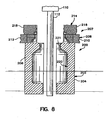
FIGURE 6 is an enlarged fragmentary front elevational view of the cap portion and dispensing nozzle of the container ofFIGURE 2 with the cap removed therefrom; -
FIGURE 7 is a enlarged fragmentary top plan view of the cap portion and dispensing nozzle of the container ofFIGURE 2 with the cap removed therefrom; -
FIGURE 8 is a fragmentary schematic diagram, partly in section, generally illustrating the apparatus of the present invention for molding, filling and sealing the container ofFIGURES 1-4 and, more particularly, the parison extrusion step of the method of the present invention for molding, filling and sealing the container ofFIGURES 1-4 ; -
FIGURE 9 is another fragmentary schematic diagram, partly in section, generally illustrating the apparatus of the present invention and the step wherein a blowing and filing nozzle is introduced to form and fill the container body; -
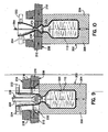
FIGURE 10 is yet another fragmentary schematic diagram, partly in section, illustrating the apparatus of the present invention and, more particularly, the step wherein the main seal mold halves are brought together to form the cap portion of the container and a mandrel is introduced for forming the frangible web and lugs around the container dispensing nozzle; -
FIGURE 11 is an enlarged fragmentary schematic diagram, partly in section, of the mandrel and main seal mold assembly as illustrated inFIGURE 10 ; -
FIGURE 12 is an enlarged fragmentary plan view of the top surface of the main seal mold assembly depicted inFIGURE 11 with the mandrel retracted therefrom and the parison removed therefrom; -
FIGURE 13 is an enlarged fragmentary vertical cross-section of a portion of the top surface of the main seal mold assembly illustrated inFIGURE 11 ; -
FIGURE 14 is yet another fragmentary schematic diagram, partly in section, illustrating the apparatus of the present invention and, more particularly, the step of the method of the present invention wherein the mandrel is removed therefrom; -
FIGURE 15 is a further fragmentary schematic diagram, partly in section, illustrating the step of the method of the present invention wherein the auxiliary seal mold halves are brought together to mold the container closure; -
FIGURE 16 is an enlarged fragmentary schematic diagram, partly in section, of the main and auxiliary seal mold assemblies in their respective closed position as illustrated inFIGURE 15 ; and -
FIGURE 17 is a fragmentary schematic diagram, partly in section, illustrating the apparatus of the present invention and, more particularly, the step wherein all of the mold assemblies are opened to allow removal of the completed container. - The invention disclosed herein is, of course, susceptible of embodiment in many different forms. Shown in the drawings and described below in detail is a preferred embodiment of the invention. It is to be understood, however, that the present disclosure is an exemplification of the principles of the invention and does not limit the invention to the illustrated embodiment.
- The precise shapes and sizes of the components described herein are not essential to the invention unless otherwise indicated.
- For ease of description, the container of the invention and the apparatus of this invention for making the container will be described in a normal (upright) operating position and terms such as upper, lower, horizontal, etc., will be used with reference to this position. It will be understood, however, that the container and apparatus of this invention may be manufactured, stored, transported, used, and sold in an orientation other than the position described.
- The apparatus of this invention has certain conventional drive and control mechanisms, the details of which are described in detail in
U.S. Patent No. 4,707,966 to Weiler et al. and further will be apparent to those having skill in the art and an understanding of the necessary functions of such mechanisms. Moreover, the method of this invention includes certain conventional steps, the details of which are also disclosed inU.S. Patent No. 4,707,966 to Weiler et al. and further will be apparent to those having skill in the art and an understanding of the necessary steps of such method. - A thermoplastic container structure embodying the present invention will first be described. This will be followed by a description of an apparatus and method for molding, filling, and sealing the container.
- A formed, filled, and hermetically sealed
container 50 of the present invention is illustrated inFIGURES 1-4 . Thecontainer 50 is preferably fabricated from conventional thermoplastic molding materials such as polyethylene (low or high density), polypropylene, and the like materials compatible with the container contents. - The teachings of the present invention find application in the production of filled and unfilled containers having a wide variety of shapes and sizes.
Container 50 is an example of one such container and includes ahollow body portion 52 having abottom surface 54 and a top 56, acap portion 72 that terminates in a dispensingnozzle 76, and aclosure portion 92 thatseals dispensing nozzle 76. The container bottom 54 includes two humped end surfaces 58 and 60 and a flat surface orland 62 therebetween. A generallyU-shaped support ring 64 extends outwardly away from theflat surface 62. Thering 64 is disposed generally co-planar with the mold parting line 67 (FIGURE 3 ) ofcontainer 50. The top 56 ofcontainer body portion 52 terminates in aneck 66 unitary therewith which includes a generallycylindrical throat 68 defining a hollow passageway 70 (FIGURE 6 ) for dispensing container contents. -
Throat 68 in turn, terminates incap portion 72 unitary therewith.Cap portion 72 is provided with dispensingnozzle 76 which, in turn, is sealed byclosure portion 92.Cap portion 72,nozzle 76 andclosure portion 92 are unitary with one another, butclosure portion 92 is removable from dispensingnozzle 76 upon fracture of a frangible web that removably connectsclosure portion 92 to dispensingnozzle 76. - A
grip tab 96 in the shape of an inverted "U" (FIGURES 2 and 3 ) surrounds theclosure portion 92.Tab 96 includes two spaced apartwings bridge 102 therebetween.Bridge 102 is unitary with and extends generally longitudinally above the top ofclosure portion 92.Wings bridge 102 and extend generally vertically downwardly therefrom.Wings inclined end surface 104 spaced from and positioned generally adjacent and parallel to thefrustoconical base 74 ofcap portion 72. Each of thewings inner surface 106 spaced from and positioned generally adjacent and parallel to the dispensingnozzle 76. - The
throat 68 ofneck 66 is unitary withcap portion 72. As shown inFIGURE 6 ,cap portion 72 includes a substantiallyfrustoconical base 74 unitary withthroat 68 and a generally cylindrical dispensingnozzle 76 unitary with and extending in a direction away from thebase 74. - Dispensing
nozzle 76 includes aninner surface 78, anouter surface 79 and a topperipheral surface 80.Inner surface 78 defines an open, axial passageway in communication with apassageway 82 inbase 74 which in turn is in communication with thepassageway 70 and thehollow body portion 52 ofcontainer 50.Inner surface 78 of dispensingnozzle 76 is tapered inwardly from thetop end 80 towards the base 74 so as to receive and seat a draining spike. - As illustrated in
FIGURES 5-7 , alip 84 extends radially and circumferentially outwardly from theouter surface 79 of dispensingnozzle 76 about the top opendistal end 80 thereof which defines an axial access aperture. A pair of diametrically opposed ear-shaped locking lugs 88 and 90 extend radially outwardly from thelip 84. - As stated hereinabove,
closure portion 92 is unitary withnozzle 76. In particular,closure portion 92 includes a bottom circumferential edge 93 (FIGURE 5 ) which is unitary with thelip 84 and lugs 88 and 90 on dispensingnozzle 76. Thelip 84 and lugs 88 and 90 are delineated from the bottomcircumferential edge 93 ofclosure portion 92 by afrangible web 94 which is unitary with dispensingnozzle 76 andclosure portion 92 and which surrounds the peripheral edge oflip 84 and lugs 88 and 90. - To dispense container contents,
closure portion 92 is severed and removed from thenozzle 76 by grasping thewings tab 96 and then exerting a simultaneous twisting and lifting motion to theclosure portion 92 so as to breakfrangible web 94. Once theclosure portion 92 has been removed, a Luer™ fitting or a draining spike (not shown) may be secured tonozzle 76.Lugs nozzle 76 are sized to engage the Luer™ lock threads of such a Luer™ fitting and theinner surface 78 of dispensingnozzle 76 is adapted to receive a draining spike. Preferably, the inner passageway defined bysurface 78 has controlled dimensions as will be discussed in greater detail hereinbelow. - The apparatus and method for molding containers embodying the present invention such as
container 50 will next be discussed with reference to the schematic, partially cross-sectional diagrams ofFIGURES 8-17 . These Figures show the apparatus and progressively illustrate the sequence of the steps of the method of container fabrication. - As best illustrated in
FIGURE 8 , the method of forming thecontainer 50 is initiated at anextruder head 110 of conventional design which is adapted to extrude length ofparison 112 in the form of a elongated, hollow tube of a semimolten thermoplastic material. - A
mold assembly 200 is positioned in spaced relationship from and around the extrudedparison 112. Themold assembly 200 includes a lowermain mold assembly 202 including a pair of main coacting mold halves 204 and 206, aseal mold assembly 207 including a mainseal mold assembly 208 having a pair of coacting mainseal mold halves seal mold assembly 214 having a pair of coacting auxiliaryseal mold halves seal mold assembly 208 and auxiliaryseal mold assembly 214 may be parts of the same assembly or may be separate seal mold assemblies, as desired. - Main
seal mold halves main mold halves seal mold halves main mold halves - Auxiliary
seal mold halves seal mold halves seal mold assembly 208. Auxiliaryseal mold halves seal mold halves main mold halves - Typically, more than one
container 50 is fabricated at one time in a multi-cavity mold assembly. For ease of description, however, only a single mold cavity is illustrated. It is to be realized, however, that themold assembly 200 may include a plurality of mold assemblies aligned in a row and that a plurality of extruder heads 110 may be provided in a row for extruding a length of parison between each of the mold assemblies. - According to the invention, and referring to
FIGURE 8 ,parison 112 is initially extruded and depends vertically downwardly between each of themold assemblies main mold halves FIGURE 8 to the main mold closed position illustrated inFIGURE 9 by suitable means, such as a pneumatic or hydraulic actuator or actuators (not illustrated). Themain mold halves body cavity 220 and a top cylindrical opening 221 (FIGURE 8 ). - Next, and as also illustrated in
FIGURE 9 , the upper end of theparison 112 extending above theseal mold assemblies operable jaws parison 112 prevented from collapsing by the holdingjaws parison 112 is then severed as illustrated inFIGURE 9 above the holdingjaws - Initially, and as also illustrated in
FIGURE 9 , a blowing and fillingassembly 228 including amandrel 229 and anozzle 230 is moved into registry with the opening at the upper end of the severed segment ofparison 112 and thereafter extended downwardly into the opening at the upper end of the severed segment ofparison 112. Thenozzle 230 is then positioned abutting theopening 221 in the top of closedmain mold assembly 202. -
Mandrel 229 preferably includes a conventional blowing tube and a conventional filling tube (neither being visible inFIGURE 9 ). In operation, gas under pressure, such as air or the like, is then discharged through the mandrel blowing tube and thenozzle 230 into the interior ofparison 112 to expand theparison segment 112 outwardly against the walls of thecavity 220 defined by themain mold assembly 202 to mold the sidewall ofcontainer body portion 52, the container bottom 54, thering 64, and theneck 66. - Next, the filling tube inside the
composite mandrel 229 is reciprocated downwardly to open a vent passage in themandrel 229 to permit venting of the compressed gas out of the molded container. Subsequently, the blowing tube is moved downwardly a small amount within themandrel 229 to open a product dispensing valve and permit the product to be injected under pressure from the filling tube, through thenozzle 230 and into the formedcontainer body portion 52. - After the formed
container body portion 52 has been filled with the desired amount of product, thecomposite mandrel 229 is withdrawn from the open end of the segment ofparison 112. - Then, the main
seal mold halves FIGURES 10 and11 by suitable conventional actuators (not shown) to a sealing position wherein the mold halves 210 and 212 cooperate together to define acap cavity 232 in communication with thebody cavity 220 for forming and molding the sidewall of thecap portion 72 ofcontainer 50. Referring toFIGURE 11 ,cap cavity 232 includes an inner frustoconical surface 234 and an innercylindrical surface 236 unitary with and extending upwardly from surface 234. Theinner surfaces 234 and 236 also include an axial groove 237 (FIGURE 9 ). The segment ofparison 112 betweenseal mold halves surfaces 234 and 236 ofcavity 232 when the mold halves 210 and 212 are closed to define and mold thefrustoconical base 74 and dispensingnozzle 76, respectively, ofcap portion 72. Moreover, when the mainseal mold halves groove 237 is filled with the thermoplastic material that constitutesparison 112 to define and mold the peripheral edges ofwings grip tab 96. - The main
seal mold halves horizontal surface 238. The innercylindrical surface 236 of mainseal mold assembly 208 terminates at the top surface 238 (FIGURE 12 ) to define a generallycircular opening 239 with acircumferential edge 240. - The
top surface 238 includes a generally horizontal recessed surface 242 (FIGURE 13 ) which extends radially outwardly from, and circumferentially around, theedge 240. Thesurface 242 is co-planar with the top of opening 239 defined by innercylindrical surface 236. A sidewall 244 extends generally outwardly and axially away from the end of recessedsurface 242 opposite the end thereof connected to edge 240. Sidewall 244 also extends circumferentially aroundedge 240. A generally horizontaltop wall 246, which is parallel to but spaced axially and radially fromsurface 242, extends radially outwardly from the end ofwall 246 opposite the end thereof connected to wall 242 and circumferentially aroundedge 240. Asidewall 248 extends radially and angularly outwardly and downwardly from the end oftop wall 246 opposite the end thereof connected to sidewall 244.Sidewall 248 likewise extends circumferentially aroundedge 240. Moreover, a generallyhorizontal surface 250 extends radially outwardly from the end ofsidewall 248 opposite the end thereof connected totop wall 246.Surface 250 also extends circumferentially aroundedge 240.Surface 250 is generally parallel tosurfaces - The
sidewall 248 andsurface 250 define aclosure edge cavity 262 extending circumferentially aroundedge 240 ofopening 239 and radially outwardly from the periphery ofknife edge 260. -
Surface 242 and sidewall 244 define anannular cavity 252 including a ring-shapedportion 254 which extends circumferentially aroundedge 240 ofopening 239 and twoopposed ears portion 254. - The
sidewalls 244 and 248 and thetop wall 246 therebetween define an upstandingperipheral knife edge 260 protruding axially outwardly from thetop surface 238 of mainseal mold assembly 208.Knife edge 260 forms the frangible web for the container and is spaced from theedge 240 ofopening 239 and extends circumferentially aroundannular cavity 252 and, more particularly, extends around the peripheral edge of the ring-shapedportion 254 andears annular cavity 252. -
Knife edge 260 may include any other suitable configuration including the configuration wheresidewalls 244 and 248 extend angularly outwardly from thesurface 238 and converge above thesurface 238 to define a knife point. - Referring back to
FIGURES 10 and11 , after the mainseal mold halves cap portion 72, a formingassembly 264 including amandrel 266 is moved into registry with the opening at the upper end of the severed segment ofparison 112 and thereafter extended downwardly into the open upper end thereof. Themandrel 266 includes a base 268 having a lower flatradial surface 270 and afrustoconical molding member 272 unitary with and extending away from theradial surface 270 in a direction opposite thebase 268.Molding member 272 includes an outerfrustoconical surface 274 which converges in the direction away from theradial surface 270. -
Mandrel 266 is extended downwardly into the open upper end ofparison 112 and is positioned such that theradial surface 270 ofbase 268 abuts and urges against theparison 112 over thetop surface 238 of mainseal mold assembly 208 and, more particularly, against theparison 112 overlying theknife edge 260 and the annular andclosure edge cavities parison 112 against thetop wall 246 ofknife edge 260 which, in turn, causes a substantial reduction in the thickness of theparison 112 being pressed against theknife edge 260. As a result, the segment ofparison 112 overlying theknife edge 260 is almost but not quite severed and thus the frangible web 94 (FIGURE 5 ) ofcontainer 50 is formed. - Urging of the
parison 112 against thetop surface 238 of mainseal mold assembly 208 also causes the thermoplastic material ofparison 112 to fill theannular cavity 252 so as to mold thelip 84 and lugs 88 and 90 ofcap portion 72. In particular, and referring toFIGURES 5-7 and12 , the ring shapedportion 254 ofannular cavity 252 molds thelip 84 ofcap portion 72 while theears cavity 252 mold thelugs cap portion 72, respectively. The urging of theparison 112 against thetop surface 238 of mainseal mold assembly 208 also causes the thermoplastic material ofparison 112 to fill theclosure edge cavity 262 to mold the bottomcircumferential edge 93 of closure 92 (FIGURE 5 ). - The
molding member 272 of forming assembly 264 (FIGURE 11 ) is inserted into theopening 239 in thetop surface 238 of mainseal mold assembly 208 and theparison 112 abutting theinner surface 236 of mainseal mold assembly 208 is pressed against theinner surface 236 to form and mold the controlled insidediameter surface 78 ofcap portion 72. The formingassembly 264 is then retracted out of the open upper end of parison 112 (FIGURE 14 ) and the auxiliaryseal mold halves FIGURES 15 and16 , the sealing position. The auxiliaryseal mold halves closure cavity 276 in communication withcap cavity 232 andbody cavity 220.Closure cavity 276 includes a closure-complementary inner surface 277 for molding the side wall ofclosure 92 and sealing theclosure 92 to thecap portion 72, and atab cavity 278, located centrally above and in communication with theclosure cavity 276 for molding thebridge 102 ofgrip tab 96. Thetop cavity 278 is defined by opposed flat axialinner surfaces seal mold halves inner surfaces tab cavity 278 for forming afrangible web 286 along the top edge ofgrip tab 96. - After the
container closure 92 has been molded and thecontainer 50 and its contents thus sealed within thecontainer body portion 52, the threemold assemblies FIGURE 17 and the formed, filled and sealedcontainer 50 may be removed and deflashed by suitable convention means. - During deflashing, the projecting parison flash (at the bottom of the
container 50, around the sides of the container, and the upwardly extendingportion 288 of theparison 112 above thegrip tab 96 ofclosure 92 is broken away at thefrangible web 286 to provide a deflashed container substantially as illustrated inFIGURES 1-4 .
Claims (12)
- An apparatus for fabricating a hermetically sealed container (50), the apparatus comprising:(a) a main mold assembly (200) having two main mold halves (204, 206) together defining a body cavity (220) for the container;(b) a blowing and filling assembly (228) for forming and filling the body of the container from a parison segment (112) extending between said main mold halves and for subsequently dispensing a product into the molded body of the container;(c) a main seal mold assembly (208) having two main seal mold halves (210, 212) for receiving therebetween said parison segment and together defining a cap cavity (232) for molding a cap portion (72) of the container, said cap portion having a dispensing nozzle, said main seal mold assembly being positioned above said main mold assembly and said body cavity communicating with said cap cavity, said main seal mold assembly including a top seal mold surface (238) having an upstanding knife edge (260) extending therefrom;(d) a forming assembly (264) for urging the parison segment against said knife edge and forming a frangible web; and(e) an auxiliary seal mold assembly (214) having two auxiliary seal mold halves (216, 218) together defining a closure cavity for a closure of the container, said auxiliary seal mold assembly being movable independently of said main seal mold assembly;
characterised by(f) an annular cavity (252) between said knife edge and an opening in said top seal mold surface of said main seal mold assembly for molding a lip (84) extending outwardly from the end of the dispensing nozzle and lugs (88, 90) extending outwardly from said lip on the cap portion of the container, wherein the lip and the lugs define a peripheral edge of the dispensing nozzle and wherein the frangible web extends around said peripheral edge. - An apparatus as claimed in Claim 1, wherein said knife edge is defined by two spaced sidewalls extending outwardly from said top seal mold surface (238) and a top wall extending between said side walls.
- An apparatus as claimed in Claim 1 or Claim 2 wherein said knife edge (260) is spaced from said opening (239) in said top mold surface.
- An apparatus as claimed in any of the preceding claims, wherein said cap cavity in said main seal mold assembly is defined by an inner surface (236) terminating at said top mold surface to define said opening (239) in said top mold surface, said knife edge extending circumferentially around said opening (239).
- An apparatus as claimed in Claim 1, wherein said annular cavity includes a ring shaped portion (254) and two diametrically opposed ears (256, 258) for molding the lip and the lugs of the container, respectively.
- An apparatus as claimed in Claim 5, wherein said knife edge extends circumferentially around the periphery of said ring and said ears of said annular cavity.
- An apparatus as claimed in any of the preceding claims, wherein said top seal mold surface of said main seal mold assembly includes a cap closure edge cavity extending radially outwardly from said knife edge for molding the peripheral bottom edge of said closure of said container.
- An apparatus as claimed in any of the preceding claims, wherein said forming assembly includes a mandrel (266) having a base (268) with a bottom surface abutting and urging said parison segment against said knife edge of said main seal mold assembly for forming said frangible web,
- An apparatus as claimed in any of the preceding claims, wherein the dispensing nozzle has a controlled diameter inside passageway, said forming assembly including a molding member with a controlled diameter outer surface, said molding member extending into said opening in said top mold surface of said main seal mold assembly and urging said parison segment against said inside surface of said dispensing nozzle to form the controlled diameter inside passageway of said dispensing nozzle of said dispensing nozzle of said container.
- A method of fabricating a filled, hermetically sealed container, and comprising the steps of:a) providing a main mold assembly (200) having two main mold halves (204, 206) together defining a body cavity (220) for the container;b) providing a main seal mold assembly (208) having two main seal mold halves (210, 212) together defining a cap cavity (232) for molding a cap portion of the container, said cap portion having a dispensing nozzle, said main seal mold assembly being located above said main mold assembly and said body cavity communicating with said cap cavity, said main seal mold assembly including a top surface (238) having an upstanding knife edge (260) extending therefrom;c) providing an auxiliary seal mold assembly (214) having two auxiliary seal mold halves (216, 218) together defining a closure cavity for a closure of the container, said auxiliary seal mold assembly being located above said main assembly and said closure cavity communicating with said body and cap cavities;d) extruding and extending the parison (112) vertically between said main mold halves and said main and auxiliary seal mold halves;e) closing said main mold halves about the parison to confine a segment of the parison between said main mold halves;f) severing the parison segment above the auxiliary seal mold assembly to provide an opening at the upper end of the parison segment;g) providing a blowing and filling assembly (228) including a blowing and filling nozzle;h) extending said blowing and filling assembly through the top opening in the parison;i) blowing gas through said blowing nozzle and into the parison segment to mold the body of the container;j) discharging a product through the filling nozzle into the body of the molded container to fill the container;k) retracting the blowing and filling assembly from the top opening of the parison;l) closing said main seal mold halves about the parison segment to confine a portion of the parison segment therebetween to mold the cap portion (72) of the container;m) providing a forming assembly including a mandrel (266);n) extending said mandrel through the top opening in the parison segment into abutting relationship with the parison over said top surface of said main seal mold assembly;o) urging said mandrel against the parison over said top seal mold surface of said main mold assembly into said annular cavity and against said knife edge for molding a lip (84) to extend outwardly from the end of the dispensing nozzle, and lugs (88, 90) extending outwardly from said lip on said cap portion of said container such that the lip and the lugs define a peripheral edge of the dispensing nozzle, and for forming a frangible web (94) between the peripheral edge and the closure of the container, the frangible web extending around the peripheral edge;p) retracting the forming assembly from the top opening of the parison segment;q) closing said auxiliary seal mold halves about the parsion segment to confine a portion of the parison segment therebetween to mold the closure of the container and seal the cap portion of the container to the closure of the container;r) opening said main mold assembly and said main seal mold assembly and said auxiliary seal mold assembly; ands) removing the molded container.
- A method as claimed in Claim 10, wherein the cap portion of the container has a controlled diameter inner passageway (236), said mandrel including a molding member having a controlled diameter outer surface, the method further comprising the step of extending said molding member in said opening in said top surface of said main seal mold assembly and urging said mold member against the parison abutting the inner surface of said cap portion to from the controlled diameter inner passageway of said cap portion of said container.
- A method as claimed In Claim 10 wherein said forming assembly includes a molding member (272) having a controlled outer diameter, the method further comprising; introducing said forming assembly into the top opening and urging said forming assembly against the severed parison segment and said severed parison segment against the main mold halves to form a controlled diameter inner passageway (246) for the container of lugs (88, 90) on the container surrounding the inner passageway.
Priority Applications (1)
| Application Number | Priority Date | Filing Date | Title |
|---|---|---|---|
| DE69738001T DE69738001T3 (en) | 1996-04-23 | 1997-04-23 | Hermetically sealed container with breakable tape and closure tabs, and method and apparatus for making same |
Applications Claiming Priority (3)
| Application Number | Priority Date | Filing Date | Title |
|---|---|---|---|
| US637944 | 1996-04-23 | ||
| US08/637,944 US5901865A (en) | 1996-04-23 | 1996-04-23 | Hermetically sealed container with frangible web and locking lugs and method and apparatus for making same |
| EP97302784A EP0803443B2 (en) | 1996-04-23 | 1997-04-23 | Hermetically sealed container with frangible web and locking lugs and method and apparatus for making same |
Related Parent Applications (2)
| Application Number | Title | Priority Date | Filing Date |
|---|---|---|---|
| EP97302784A Division EP0803443B2 (en) | 1996-04-23 | 1997-04-23 | Hermetically sealed container with frangible web and locking lugs and method and apparatus for making same |
| EP97302784.0 Division | 1997-04-23 |
Publications (4)
| Publication Number | Publication Date |
|---|---|
| EP1362685A2 EP1362685A2 (en) | 2003-11-19 |
| EP1362685A3 EP1362685A3 (en) | 2004-09-15 |
| EP1362685B1 EP1362685B1 (en) | 2007-08-08 |
| EP1362685B2 true EP1362685B2 (en) | 2011-07-27 |
Family
ID=24558004
Family Applications (2)
| Application Number | Title | Priority Date | Filing Date |
|---|---|---|---|
| EP03012888A Expired - Lifetime EP1362685B2 (en) | 1996-04-23 | 1997-04-23 | Hermetically sealed container with frangible web and locking lugs and method and apparatus for making same |
| EP97302784A Expired - Lifetime EP0803443B2 (en) | 1996-04-23 | 1997-04-23 | Hermetically sealed container with frangible web and locking lugs and method and apparatus for making same |
Family Applications After (1)
| Application Number | Title | Priority Date | Filing Date |
|---|---|---|---|
| EP97302784A Expired - Lifetime EP0803443B2 (en) | 1996-04-23 | 1997-04-23 | Hermetically sealed container with frangible web and locking lugs and method and apparatus for making same |
Country Status (6)
| Country | Link |
|---|---|
| US (3) | US5901865A (en) |
| EP (2) | EP1362685B2 (en) |
| JP (1) | JP4434328B2 (en) |
| CN (1) | CN1081577C (en) |
| AU (1) | AU727375B2 (en) |
| DE (2) | DE69725207T3 (en) |
Families Citing this family (38)
| Publication number | Priority date | Publication date | Assignee | Title |
|---|---|---|---|---|
| US6068148A (en) * | 1998-05-26 | 2000-05-30 | Automatic Liquid Packaging, Inc. | Hermetically sealed container including a nozzle with a sealing bead |
| DE10050660B4 (en) | 2000-10-13 | 2018-06-28 | Robert Bosch Gmbh | Method and device for producing containers filled and sealed with sterile products |
| US6626308B2 (en) | 2001-01-26 | 2003-09-30 | Weiler Engineering, Inc. | Hermetically sealed container with self-draining closure |
| USD463290S1 (en) | 2001-06-15 | 2002-09-24 | The Dannon Company, Inc. | Bottle with cap |
| USD456507S1 (en) | 2001-07-20 | 2002-04-30 | Lemarr Stephen Todd | Nebulizer vials |
| US6619516B2 (en) * | 2002-02-05 | 2003-09-16 | Weiler Engineering, Inc. | Hermetically sealed container with unitary drop-dispenser |
| US7033378B2 (en) * | 2002-09-20 | 2006-04-25 | Id, Llc | Surgical fastener, particularly for the endoluminal treatment of gastroesophageal reflux disease (GERD) |
| EP1556646B1 (en) * | 2002-10-07 | 2013-12-18 | Becton, Dickinson and Company | Method for filling a container having at least one flexible component |
| DE10254762A1 (en) * | 2002-11-22 | 2004-06-09 | Transcoject Gesellschaft für medizinische Geräte mbH & Co. KG | Process for producing and / or handling a high-purity object |
| US7185790B2 (en) * | 2003-03-20 | 2007-03-06 | Weiler Engineering, Inc. | Hermetically sealed container with non-drip opening |
| US7040497B2 (en) * | 2003-08-26 | 2006-05-09 | Weiler Engineering, Inc. | Hermetically sealed container with child safety overcap |
| RU2428311C2 (en) * | 2005-12-20 | 2011-09-10 | Альпла Верке Альвин Ленер Гмбх Унд Ко.Кг | Billet for fabricating plastic tube and plastic tube made thereof |
| US7832601B2 (en) * | 2005-12-21 | 2010-11-16 | The Ritedose Corporation | Dispensing container with nipple dispensing head |
| US7866514B1 (en) | 2006-03-01 | 2011-01-11 | Bernd Hansen | Container and device for production of such container |
| WO2008031447A1 (en) | 2006-09-15 | 2008-03-20 | Alpla-Werke Alwin Lehner Gmbh & Co. Kg | Parison and method for the production of plastics bottles |
| EP2141075B1 (en) * | 2007-04-27 | 2012-10-31 | Daiwa Can Company | Polyester resin container with fracturable portion and its production method |
| JP4986876B2 (en) * | 2008-02-02 | 2012-07-25 | ヒタチグローバルストレージテクノロジーズネザーランドビーブイ | Disk drive device |
| JP4811428B2 (en) * | 2008-04-25 | 2011-11-09 | 株式会社デンソー | Insert molding method |
| EP2143543A1 (en) * | 2008-07-07 | 2010-01-13 | Nestec S.A. | Device and method for packaging a liquid food product |
| CN101596941B (en) * | 2009-07-03 | 2011-07-27 | 阳江喜之郎果冻制造有限公司 | Air-exhausting bag clamping device with straw packaging bag and packaging method using same |
| US20110315720A1 (en) * | 2010-06-28 | 2011-12-29 | Unicep Packaging, Inc. | Dispenser with twist lock fitting |
| DE102010027617A1 (en) * | 2010-07-20 | 2012-01-26 | Bernd Hansen | Method and device for producing and filling containers made of thermoplastic material and containers produced in this way |
| US8486324B2 (en) | 2010-07-23 | 2013-07-16 | Automatic Liquid Packaging Solutions Llc | Method and apparatus for producing tiered containers |
| CH704965A1 (en) * | 2011-05-16 | 2012-11-30 | Alpla Werke | Procedures to ensure the dimensional accuracy of a pour opening in or on a prepared in an extrusion blow molding plastic containers. |
| JP6062638B2 (en) * | 2012-01-31 | 2017-01-18 | キョーラク株式会社 | Infusion bottle |
| WO2013117492A1 (en) * | 2012-02-10 | 2013-08-15 | Nestec S.A. | A method of blowing, filling and capping containers |
| WO2014060101A1 (en) * | 2012-10-16 | 2014-04-24 | Kocher-Plastik Maschinenbau Gmbh | Device for producing container products consisting of plastic materials |
| US9867973B2 (en) | 2013-06-17 | 2018-01-16 | Medline Industries, Inc. | Skin antiseptic applicator and methods of making and using the same |
| US10456328B2 (en) * | 2013-09-12 | 2019-10-29 | Fresenius Kabi Deutschland Gmbh | Ampoule for medical liquid and method for producing an ampoule |
| UY36193A (en) | 2014-07-22 | 2016-02-29 | Bayer Animal Health Gmbh | TUBE WITH AN APPLICATION POINT |
| WO2016032814A1 (en) * | 2014-08-25 | 2016-03-03 | Weiler Engineering, Inc. | Hermetically sealed, liquid containing ampoule |
| NO337769B1 (en) * | 2014-10-14 | 2016-06-20 | Hexagon Raufoss As | Process and tools for producing a clamp-free liner |
| US10363369B2 (en) * | 2015-01-14 | 2019-07-30 | Weiler Engineering, Inc. | Ampoule with dual Luer fitting |
| CN109702991B (en) * | 2019-01-25 | 2023-09-22 | 沂水金誉塑业有限公司 | Plastic drum production facility convenient to blow molding |
| CH717442A1 (en) * | 2020-05-18 | 2021-11-30 | Alpla Werke Alwin Lehner Gmbh & Co Kg | Plastic container. |
| CN116323156B (en) * | 2020-08-27 | 2026-01-27 | 索诺克发展有限公司 | System and method for application and sealing of end closures on containers |
| WO2023137167A1 (en) * | 2022-01-13 | 2023-07-20 | Koska Family Limited | Systems and methods for rotary blow-fill-seal (bfs) machine mold positioning |
| US20240226439A9 (en) * | 2022-10-21 | 2024-07-11 | Merck Sharp & Dohme Llc | Blow-fill sealing method for filling and packaging |
Citations (1)
| Publication number | Priority date | Publication date | Assignee | Title |
|---|---|---|---|---|
| DE2255869A1 (en) † | 1972-11-15 | 1974-05-16 | Gerhard Hansen | DEVICE FOR MANUFACTURING, FILLING AND SEALING A CONTAINER FROM A HEAT SEALABLE PLASTIC HOSE |
Family Cites Families (28)
| Publication number | Priority date | Publication date | Assignee | Title |
|---|---|---|---|---|
| US3124273A (en) * | 1964-03-10 | Metallic collapsible tubes having | ||
| US3187966A (en) * | 1963-07-09 | 1965-06-08 | Continental Can Co | Flexible container with snip-off and reseal features |
| US3597793A (en) * | 1969-05-28 | 1971-08-10 | Automatic Liquid Packaging | Bottles and the method and apparatus for forming them |
| US3809276A (en) * | 1972-09-27 | 1974-05-07 | Eyelet Specialty Co | Plastic bottle and cap construction |
| US3923179A (en) * | 1973-03-07 | 1975-12-02 | American Hospital Supply Corp | Medical liquid container with tactile sterility indicator and method of testing container |
| US4176153A (en) * | 1978-02-10 | 1979-11-27 | Automatic Liquid Packaging, Inc. | Unitary, hermetically-sealed but pierceable dispensing container |
| US4207990A (en) * | 1979-05-03 | 1980-06-17 | Automatic Liquid Packaging, Inc. | Hermetically sealed container with plural access ports |
| DE3033821C2 (en) * | 1980-09-09 | 1982-09-09 | Gerhard 7166 Sulzbach-Laufen Hansen | Method and device for producing a container from a heat-sealable plastic tube and containers produced by the method and by means of the device |
| US4405053A (en) * | 1981-04-27 | 1983-09-20 | Abbott Laboratories | Tamperproof closure system for plastic containers |
| US4596110A (en) * | 1981-08-26 | 1986-06-24 | Automatic Liquid Packaging, Inc. | Container with insert having a fully or partially encapsulating seal with a frangible web formed against said insert |
| US4707966A (en) * | 1981-08-26 | 1987-11-24 | Automatic Liquid Packaging, Inc. | Container with an encapsulated top insert and method and apparatus for making same |
| US4821897A (en) * | 1981-08-26 | 1989-04-18 | Automatic Liquid Packaging, Inc. | Container with insert having a fully or partially encapsulating seal with a frangible web formed against said insert |
| US4402420A (en) * | 1981-12-07 | 1983-09-06 | Extracorporeal Medical Specialties, Inc. | Dual function port cap |
| DE88056T1 (en) * | 1982-02-08 | 1984-03-01 | Astra Laekemedel Ab, 15185 Soedertaelje | CONTAINER FILLED WITH NORMAL DOSIS. |
| US4467930A (en) * | 1982-04-06 | 1984-08-28 | Baxter Travenol Laboratories, Inc. | Overmolded closure seal |
| GB2124992B (en) * | 1982-08-03 | 1986-05-21 | Schering Prebbles Ltd | Receptacles for releasing medicines at different rates |
| US4519513A (en) * | 1982-08-30 | 1985-05-28 | Automatic Liquid Packaging, Inc. | Container having pierceable insert |
| US4584823A (en) * | 1983-06-06 | 1986-04-29 | Heinz Plastic Mold Co. | Improved method and apparatus for blow molding in a single blow molding operation a controlled drop bottle |
| US4671763A (en) * | 1983-06-29 | 1987-06-09 | Automatic Liquid Packaging, Inc. | Container with a unitary but removable closure and method and apparatus therefor |
| DE3328158A1 (en) * | 1983-08-04 | 1985-02-21 | Hansen, Gerhard, 7166 Sulzbach-Laufen | CONTAINER, ESPECIALLY AMPOULE, BOTTLE OR THE LIKE PLASTIC |
| US4539172A (en) * | 1983-12-16 | 1985-09-03 | Baxter Travenol Laboratories, Inc. | Method of blowmolding a container having an integral inner dispensing outlet |
| DE68907384T2 (en) * | 1988-06-10 | 1993-10-14 | Becton Dickinson Co | Roller bottle with an enlarged surface. |
| US4886175A (en) * | 1989-04-10 | 1989-12-12 | Merck & Co., Inc. | Bottle and cap closure system |
| US5409125A (en) * | 1989-12-11 | 1995-04-25 | Aktiebolaget Astra | Unit dose container |
| US5054267A (en) * | 1990-08-06 | 1991-10-08 | Graham Engineering Corporation | Apparatus sealing blow molded bottle |
| US5121856A (en) * | 1990-11-30 | 1992-06-16 | Automatic Liquid Packaging, Inc. | Sleeved dispensing vial |
| US5188250B1 (en) * | 1992-06-05 | 1994-07-05 | Kraft Gen Foods Inc | Plastic beverage bottle with twist-off closure |
| US5351462A (en) * | 1993-06-02 | 1994-10-04 | Automatic Liquid Packaging, Inc. | Method and apparatus for installing an insert to seal a container |
-
1996
- 1996-04-23 US US08/637,944 patent/US5901865A/en not_active Expired - Lifetime
-
1997
- 1997-04-10 AU AU17837/97A patent/AU727375B2/en not_active Expired
- 1997-04-22 CN CN97113013A patent/CN1081577C/en not_active Expired - Lifetime
- 1997-04-23 EP EP03012888A patent/EP1362685B2/en not_active Expired - Lifetime
- 1997-04-23 DE DE69725207T patent/DE69725207T3/en not_active Expired - Lifetime
- 1997-04-23 EP EP97302784A patent/EP0803443B2/en not_active Expired - Lifetime
- 1997-04-23 JP JP10601897A patent/JP4434328B2/en not_active Expired - Lifetime
- 1997-04-23 DE DE69738001T patent/DE69738001T3/en not_active Expired - Lifetime
-
1999
- 1999-05-11 US US09/309,920 patent/US6168413B1/en not_active Expired - Lifetime
-
2000
- 2000-12-14 US US09/736,638 patent/US6381926B1/en not_active Expired - Lifetime
Patent Citations (1)
| Publication number | Priority date | Publication date | Assignee | Title |
|---|---|---|---|---|
| DE2255869A1 (en) † | 1972-11-15 | 1974-05-16 | Gerhard Hansen | DEVICE FOR MANUFACTURING, FILLING AND SEALING A CONTAINER FROM A HEAT SEALABLE PLASTIC HOSE |
Also Published As
| Publication number | Publication date |
|---|---|
| EP0803443B2 (en) | 2008-04-09 |
| EP0803443A2 (en) | 1997-10-29 |
| US6381926B1 (en) | 2002-05-07 |
| EP1362685A2 (en) | 2003-11-19 |
| JPH1052855A (en) | 1998-02-24 |
| AU727375B2 (en) | 2000-12-14 |
| EP1362685B1 (en) | 2007-08-08 |
| AU1783797A (en) | 1997-10-30 |
| US5901865A (en) | 1999-05-11 |
| EP0803443B1 (en) | 2003-10-01 |
| DE69738001T2 (en) | 2008-05-08 |
| EP0803443A3 (en) | 2001-02-28 |
| JP4434328B2 (en) | 2010-03-17 |
| DE69738001D1 (en) | 2007-09-20 |
| DE69725207T2 (en) | 2004-05-06 |
| DE69725207D1 (en) | 2003-11-06 |
| EP1362685A3 (en) | 2004-09-15 |
| DE69738001T3 (en) | 2012-01-05 |
| US6168413B1 (en) | 2001-01-02 |
| DE69725207T3 (en) | 2008-07-10 |
| CN1174157A (en) | 1998-02-25 |
| CN1081577C (en) | 2002-03-27 |
Similar Documents
| Publication | Publication Date | Title |
|---|---|---|
| EP1362685B2 (en) | Hermetically sealed container with frangible web and locking lugs and method and apparatus for making same | |
| US4671763A (en) | Container with a unitary but removable closure and method and apparatus therefor | |
| US5429789A (en) | Plastic container with self-draining feature | |
| AU749384B2 (en) | Hermetically sealed container including a nozzle with a sealing bead | |
| US5158192A (en) | Dispensing bottle with coupling between closure head and screw cap | |
| US4298045A (en) | Dispensing container with plural removable closure means unitary therewith | |
| US4207990A (en) | Hermetically sealed container with plural access ports | |
| US4821897A (en) | Container with insert having a fully or partially encapsulating seal with a frangible web formed against said insert | |
| EP1480891B1 (en) | Hermetically sealed container with unitary drop-dispenser | |
| US4596110A (en) | Container with insert having a fully or partially encapsulating seal with a frangible web formed against said insert | |
| US4540542A (en) | Method for making a container with a unitary but removable closure | |
| CA1319909C (en) | Plastic container with self-draining feature | |
| US4901873A (en) | Container with insert having a fully or partially encapsulating seal with a frangible web formed against said insert | |
| US4239726A (en) | Method for forming, filling and sealing a container having plural closures | |
| EP0627298B1 (en) | Method and apparatus for forming retaining flange around container closure | |
| US4699748A (en) | Container with insert having a fully or partially encapsulating seal with a frangible web formed against said insert | |
| AU676925B2 (en) | Collapsible package | |
| EP0489572A1 (en) | Hermetically sealed vial | |
| AU725401B2 (en) | Hermetically sealed container with closure insert | |
| US4425294A (en) | Method for molding and filling a dispensing container having one or more removable closure means unitary therewith | |
| CA1228308A (en) | Molded container with a top opening | |
| HK1000590B (en) | Plastic container with self-draining feature |
Legal Events
| Date | Code | Title | Description |
|---|---|---|---|
| PUAI | Public reference made under article 153(3) epc to a published international application that has entered the european phase |
Free format text: ORIGINAL CODE: 0009012 |
|
| 17P | Request for examination filed |
Effective date: 20030606 |
|
| AC | Divisional application: reference to earlier application |
Ref document number: 0803443 Country of ref document: EP Kind code of ref document: P |
|
| AK | Designated contracting states |
Kind code of ref document: A2 Designated state(s): CH DE GB IT LI |
|
| RIN1 | Information on inventor provided before grant (corrected) |
Inventor name: WEILER, GERHARD H. Inventor name: RAMRAKHYANI, ARJUN |
|
| PUAL | Search report despatched |
Free format text: ORIGINAL CODE: 0009013 |
|
| AK | Designated contracting states |
Kind code of ref document: A3 Designated state(s): CH DE GB IT LI |
|
| AKX | Designation fees paid |
Designated state(s): CH DE GB IT LI |
|
| GRAP | Despatch of communication of intention to grant a patent |
Free format text: ORIGINAL CODE: EPIDOSNIGR1 |
|
| GRAS | Grant fee paid |
Free format text: ORIGINAL CODE: EPIDOSNIGR3 |
|
| GRAA | (expected) grant |
Free format text: ORIGINAL CODE: 0009210 |
|
| AC | Divisional application: reference to earlier application |
Ref document number: 0803443 Country of ref document: EP Kind code of ref document: P |
|
| AK | Designated contracting states |
Kind code of ref document: B1 Designated state(s): CH DE GB IT LI |
|
| REG | Reference to a national code |
Ref country code: GB Ref legal event code: FG4D |
|
| REG | Reference to a national code |
Ref country code: CH Ref legal event code: EP |
|
| REF | Corresponds to: |
Ref document number: 69738001 Country of ref document: DE Date of ref document: 20070920 Kind code of ref document: P |
|
| REG | Reference to a national code |
Ref country code: CH Ref legal event code: NV Representative=s name: KIRKER & CIE S.A. |
|
| PLBI | Opposition filed |
Free format text: ORIGINAL CODE: 0009260 |
|
| PLAX | Notice of opposition and request to file observation + time limit sent |
Free format text: ORIGINAL CODE: EPIDOSNOBS2 |
|
| 26 | Opposition filed |
Opponent name: KOCHER-PLASTIK MASCHINENBAU GMBH Effective date: 20080502 |
|
| PLAF | Information modified related to communication of a notice of opposition and request to file observations + time limit |
Free format text: ORIGINAL CODE: EPIDOSCOBS2 |
|
| PLBB | Reply of patent proprietor to notice(s) of opposition received |
Free format text: ORIGINAL CODE: EPIDOSNOBS3 |
|
| PLAY | Examination report in opposition despatched + time limit |
Free format text: ORIGINAL CODE: EPIDOSNORE2 |
|
| PLAH | Information related to despatch of examination report in opposition + time limit modified |
Free format text: ORIGINAL CODE: EPIDOSCORE2 |
|
| PLBC | Reply to examination report in opposition received |
Free format text: ORIGINAL CODE: EPIDOSNORE3 |
|
| PUAH | Patent maintained in amended form |
Free format text: ORIGINAL CODE: 0009272 |
|
| STAA | Information on the status of an ep patent application or granted ep patent |
Free format text: STATUS: PATENT MAINTAINED AS AMENDED |
|
| 27A | Patent maintained in amended form |
Effective date: 20110727 |
|
| AK | Designated contracting states |
Kind code of ref document: B2 Designated state(s): CH DE GB IT LI |
|
| REG | Reference to a national code |
Ref country code: DE Ref legal event code: R102 Ref document number: 69738001 Country of ref document: DE |
|
| REG | Reference to a national code |
Ref country code: CH Ref legal event code: AEN Free format text: BREVET MAINTENU DANS UNE FORME MODIFIEE |
|
| REG | Reference to a national code |
Ref country code: DE Ref legal event code: R102 Ref document number: 69738001 Country of ref document: DE Effective date: 20110727 |
|
| PGFP | Annual fee paid to national office [announced via postgrant information from national office to epo] |
Ref country code: DE Payment date: 20160419 Year of fee payment: 20 Ref country code: GB Payment date: 20160420 Year of fee payment: 20 Ref country code: CH Payment date: 20160411 Year of fee payment: 20 |
|
| PGFP | Annual fee paid to national office [announced via postgrant information from national office to epo] |
Ref country code: IT Payment date: 20160418 Year of fee payment: 20 |
|
| REG | Reference to a national code |
Ref country code: DE Ref legal event code: R071 Ref document number: 69738001 Country of ref document: DE |
|
| REG | Reference to a national code |
Ref country code: CH Ref legal event code: PL |
|
| REG | Reference to a national code |
Ref country code: GB Ref legal event code: PE20 Expiry date: 20170422 |
|
| PG25 | Lapsed in a contracting state [announced via postgrant information from national office to epo] |
Ref country code: GB Free format text: LAPSE BECAUSE OF EXPIRATION OF PROTECTION Effective date: 20170422 |