EP1362631A1 - Separating apparatus - Google Patents
Separating apparatus Download PDFInfo
- Publication number
- EP1362631A1 EP1362631A1 EP02710507A EP02710507A EP1362631A1 EP 1362631 A1 EP1362631 A1 EP 1362631A1 EP 02710507 A EP02710507 A EP 02710507A EP 02710507 A EP02710507 A EP 02710507A EP 1362631 A1 EP1362631 A1 EP 1362631A1
- Authority
- EP
- European Patent Office
- Prior art keywords
- gas
- section
- decomposition
- separation
- separation device
- Prior art date
- Legal status (The legal status is an assumption and is not a legal conclusion. Google has not performed a legal analysis and makes no representation as to the accuracy of the status listed.)
- Withdrawn
Links
Images




Classifications
-
- C—CHEMISTRY; METALLURGY
- C01—INORGANIC CHEMISTRY
- C01B—NON-METALLIC ELEMENTS; COMPOUNDS THEREOF; METALLOIDS OR COMPOUNDS THEREOF NOT COVERED BY SUBCLASS C01C
- C01B3/00—Hydrogen; Gaseous mixtures containing hydrogen; Separation of hydrogen from mixtures containing it; Purification of hydrogen; Reversible storage of hydrogen
- C01B3/50—Separation of hydrogen or hydrogen-containing gases from gaseous mixtures, e.g. purification
-
- B—PERFORMING OPERATIONS; TRANSPORTING
- B01—PHYSICAL OR CHEMICAL PROCESSES OR APPARATUS IN GENERAL
- B01D—SEPARATION
- B01D53/00—Separation of gases or vapours; Recovering vapours of volatile solvents from gases; Chemical or biological purification of waste gases, e.g. engine exhaust gases, smoke, fumes, flue gases, aerosols
- B01D53/24—Separation of gases or vapours; Recovering vapours of volatile solvents from gases; Chemical or biological purification of waste gases, e.g. engine exhaust gases, smoke, fumes, flue gases, aerosols by centrifugal force
-
- B—PERFORMING OPERATIONS; TRANSPORTING
- B01—PHYSICAL OR CHEMICAL PROCESSES OR APPARATUS IN GENERAL
- B01D—SEPARATION
- B01D53/00—Separation of gases or vapours; Recovering vapours of volatile solvents from gases; Chemical or biological purification of waste gases, e.g. engine exhaust gases, smoke, fumes, flue gases, aerosols
- B01D53/32—Separation of gases or vapours; Recovering vapours of volatile solvents from gases; Chemical or biological purification of waste gases, e.g. engine exhaust gases, smoke, fumes, flue gases, aerosols by electrical effects other than those provided for in group B01D61/00
-
- C—CHEMISTRY; METALLURGY
- C01—INORGANIC CHEMISTRY
- C01B—NON-METALLIC ELEMENTS; COMPOUNDS THEREOF; METALLOIDS OR COMPOUNDS THEREOF NOT COVERED BY SUBCLASS C01C
- C01B3/00—Hydrogen; Gaseous mixtures containing hydrogen; Separation of hydrogen from mixtures containing it; Purification of hydrogen; Reversible storage of hydrogen
- C01B3/02—Production of hydrogen; Production of gaseous mixtures containing hydrogen
- C01B3/22—Production of hydrogen; Production of gaseous mixtures containing hydrogen by decomposition of gaseous or liquid organic compounds
- C01B3/24—Production of hydrogen; Production of gaseous mixtures containing hydrogen by decomposition of gaseous or liquid organic compounds of hydrocarbons
-
- B—PERFORMING OPERATIONS; TRANSPORTING
- B01—PHYSICAL OR CHEMICAL PROCESSES OR APPARATUS IN GENERAL
- B01D—SEPARATION
- B01D2259/00—Type of treatment
- B01D2259/80—Employing electric, magnetic, electromagnetic or wave energy, or particle radiation
- B01D2259/818—Employing electrical discharges or the generation of a plasma
-
- C—CHEMISTRY; METALLURGY
- C01—INORGANIC CHEMISTRY
- C01B—NON-METALLIC ELEMENTS; COMPOUNDS THEREOF; METALLOIDS OR COMPOUNDS THEREOF NOT COVERED BY SUBCLASS C01C
- C01B2203/00—Integrated processes for the production of hydrogen or synthesis gas
- C01B2203/02—Processes for making hydrogen or synthesis gas
- C01B2203/0266—Processes for making hydrogen or synthesis gas containing a decomposition step
-
- C—CHEMISTRY; METALLURGY
- C01—INORGANIC CHEMISTRY
- C01B—NON-METALLIC ELEMENTS; COMPOUNDS THEREOF; METALLOIDS OR COMPOUNDS THEREOF NOT COVERED BY SUBCLASS C01C
- C01B2203/00—Integrated processes for the production of hydrogen or synthesis gas
- C01B2203/04—Integrated processes for the production of hydrogen or synthesis gas containing a purification step for the hydrogen or the synthesis gas
-
- C—CHEMISTRY; METALLURGY
- C01—INORGANIC CHEMISTRY
- C01B—NON-METALLIC ELEMENTS; COMPOUNDS THEREOF; METALLOIDS OR COMPOUNDS THEREOF NOT COVERED BY SUBCLASS C01C
- C01B2203/00—Integrated processes for the production of hydrogen or synthesis gas
- C01B2203/04—Integrated processes for the production of hydrogen or synthesis gas containing a purification step for the hydrogen or the synthesis gas
- C01B2203/0465—Composition of the impurity
- C01B2203/049—Composition of the impurity the impurity being carbon
-
- C—CHEMISTRY; METALLURGY
- C01—INORGANIC CHEMISTRY
- C01B—NON-METALLIC ELEMENTS; COMPOUNDS THEREOF; METALLOIDS OR COMPOUNDS THEREOF NOT COVERED BY SUBCLASS C01C
- C01B2203/00—Integrated processes for the production of hydrogen or synthesis gas
- C01B2203/08—Methods of heating or cooling
- C01B2203/0805—Methods of heating the process for making hydrogen or synthesis gas
- C01B2203/0861—Methods of heating the process for making hydrogen or synthesis gas by plasma
Definitions
- the present invention relates to a gas separation device, which separates a gas mixture made from a variety of gases.
- An objective of the present invention is to provide a gas separation device without the above-mentioned problems.
- the present invention provides a gas separation device that is characterized by comprising: a helical claw deployed on the inside of a cylinder; an internal pipe, which is used for extraction from the center region of the cylinder; and an extraction unit, which takes out from the non-center region of the cylinder; wherein gas is jetted to the internal space of the cylinder; thus the gas is rotated by the claw, light molecules shift toward the center region, heavy molecules shift toward the non-center region due to the difference in the rotation radiuses of gas molecules, which emanates from the difference in the masses of gas constitutional materials; and as a result the gas constitutional molecules are separated.
- the present invention further provides a gas decomposition / separation device that is characterized by comprising: a gas separation device, a discharge section, which decomposes gas through discharging; and a compression section, which compresses gas from the discharge section and then jets it out to the gas separation device, which then decomposes and separates the inpoured gas.
- gas decomposition / separation devices are multi-stage cascade connected; and gas from the take out section of the gas decomposition / separation device at the very last stage is poured to the first stage, allows highly efficient gas decomposition and separation.
- a second device including a decomposition section that uses discharging and a filter to an inner pipe of the gas decomposition device of each cascade-connected stage, gas from the inner pipe of the gas decomposition / separation device of each cascade-connected stage is decomposed through discharging, and then taken out via the filter.
- FIG. 1 shows an entire configuration of a gas decomposition/ separation device 100.
- the gas decomposition/ separation device 100 is made up of three sections: a discharge section 110, a compression section 130, and a separation section 140.
- the discharge section 110 is a section that decomposes an organic gas or the like through discharging.
- the discharge section 110 is made up of en electrode 120, which discharges, and a flange pipe 112, which accommodates it.
- the compression section 130 is prepared to decrease the flow speed of the gas decomposed by the discharge 110 and increase the flow speed for the next separation section 140.
- the separation section 140 separates multiple gasses into two categories based on weight by utilizing the centrifugal force due to the pawl 142 that affects the gas. The operation of these sections is described in detail below.
- a gas mainly made from, for example, methane (CH 4 ) is introduced to the gas decomposition/ separation device 100, and then decomposed into hydrogen (H 2 ) and carbon (C) through discharging.
- the operation of the discharge section 110 is described in detail with reference to FIG. 2.
- FIG. 2 shows in detail a configuration of the electrode 120 in the discharge section 110 of FIG. 1.
- the electrode in FIG. 2 has a configuration where two opposing electrodes are combined.
- a plurality of screw-shaped stainless electrodes 122 which are deployed at almost the same intervals, protrude from a plain and rectangular insulator 124.
- Each screw-shaped electrode 122 is electrically insulated.
- a pulse electrode 120 is connected to each of the screw-shaped electrodes, which are arranged at opposing angles on the opposing electrodes.
- a mesh electrode 126 is deployed under the discharging electrodes.
- a DC power supply 154 supplies a negative bias voltage (V 0 ) to the screw electrodes 122 relative to the mesh electrode 126.
- V 0 negative bias voltage
- a pulse voltage is applied to the screw electrodes 122 from the pulse source 152 so that discharging occurs between the electrodes, thereby dissolving the methane (CH 4 ) gas into hydrogen (H 2 ) and carbon (C). This discharging occurs between the screw-shaped electrodes.
- the carbon particles dissolved from the methane gas is removed at this discharge section by falling them down as many as possible due to their own weights.
- the bias voltage to the mesh electrode 126 is adjusted so as for the voltage difference, which guides the carbon particles downward, to become an optimal value.
- dividing the discharge section into a plurality of subsections may be effective. Also, increasing the pulse frequency and electric current amount applied to the screw-shaped electrodes up to an extent where an arc-discharging does not occur is effective.
- the mixed gas including hydrogen that has been generated at the discharge section 110 is guided to the separation section 140 via the compression section 130.
- the compression section 140 is configured with a pipe whose center region is narrowed down.
- the mixed gas made of different gasses flows through a pipe that is a nozzle, which increases the linear velocity of the gas flow.
- the compression section 130 can decrease the velocity of the flow of the mixed gas (whose primary component is CH 4 ) transferred from the discharge section, and increase the flow velocity within the separation section 140.
- the mixed gas from the compression section 130 is jetted to the cylinder-shaped space that comprises the separation section 140. At this time, carbon has been left as fine particles.
- the separation section 140 has auxiliary helical (spiral) wings (claws)142 on the periphery, which give a rotation force to the gassy fluid. Once the rotation force is given to the mixed gas by these helical claws 142, the difference in the radiuses of gyration of the gas particles due to the difference in the masses of the gas constitutional materials causes the heavy particles to shift to the non-center region and the light particles to shift to the center region, and as a result the gas constitutional particles are separated.
- the rear of the separation section 140 is a duplex pipe structure, and an inner pipe 146 is connected to the inner side of the outer cylinder 143 via the mesh structure 145. Gas I, is taken out from the center region of the cylinder 143 via the inner pipe 146.
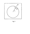
- FIG. 3 shows dynamics relevant to the mixed gas.
- centrifugal force F occurs on the gas that rotates at velocity v with a radius r 0 .
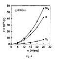
- centrifugal forces Fm, FH, and Fc are given to methane, hydrogen, and carbon, respectively, as shown in the following equations.
- m m , m H , and m c denote masses for each molecule.
- F m m m V 2 / r 0
- F H m H V 2 / r 0
- F c m c V 2 / r 0
- FIG. 4 is a graph showing the relationship between the centrifugal force that each module receives and the velocity.
- FIG. 5 shows the partial pressures in the cylinder innerside of the separation section 140.
- a center O is of the cylinder 143 that configures the separation section 140, and there are inner walls in the cylinder 143 at equal intervals.
- a high density of hydrogen exists in the center region, and a high density of methane or carbon exists in the non-center region.
- the inner pipe 146 is prepared via the mesh structure 145. A high density of the gas components of hydrogen that is a light molecule when separated as I 1 , is obtained from the inner pipe 146.
- FIG. 6 shows a configuration of a gas decomposition / separation device, which has the two-stage connected unit shown in FIG. 1.
- Sections I 222 and 232 are the unit shown in FIG. 1.
- Methane gas is sent from a gas cylinder 210 to each of the sections I 222 and 232.
- a high density of hydrogen gas is seized at the center I1 of each of the sections I 222 and 232, and then sent to the sections II 224 and 234.
- FIG. 7 shows a configuration of the section II.
- the section II is configured from a discharge section 320 and a palladium filter 340.
- the discharge section 320 which is the same configuration as the discharge section 110, decomposes the remaining methane gas so as to generate hydrogen.
- the palladium filter 340 is a transparent film made of palladium or a palladium- silver (Ag) alloy, and lets only hydrogen pass through. In section II, through the decomposition process of the discharge section 320 and then the palladium filter 340 a pure hydrogen gas is obtained.
- a low density of hydrogen gas I 2 is gathered from the non-center region of the section I 232 and the sections II 224 and 234, pressured by a pressure pump 240, and then given again to the first-stage of the section I 222. In such a manner, the decomposing and separating is repeatedly performed.
- FIG. 6 shows a two-stage cascade connected configuration example; alternatively, three or more-stage cascade connection is also available.
- Methane gas that was filled in a normal grade was given from the gas cylinder 210 to the inlet of the first stage 222 of the section I at a rate of 200 ml/sec.
- its compositional ratio of hydrogen to methane was found to be 80:20.
- the compositional ratio of hydrogen to methane included in the taken-out gas from the second stage 232 in the section I was found to be 95:5.
- a highly refined hydrogen gas, which is given from a Pd-Ag transparent film 340, is provided from each of the sections II 224 and 234.
- the separation method according to the present invention is beneficial for separating and/ or refining a large amount of gas since the greater the flow velocity, the greater the separatability.
Landscapes
- Chemical & Material Sciences (AREA)
- Organic Chemistry (AREA)
- Engineering & Computer Science (AREA)
- Oil, Petroleum & Natural Gas (AREA)
- Inorganic Chemistry (AREA)
- Analytical Chemistry (AREA)
- General Chemical & Material Sciences (AREA)
- Combustion & Propulsion (AREA)
- Chemical Kinetics & Catalysis (AREA)
- Health & Medical Sciences (AREA)
- General Health & Medical Sciences (AREA)
- Hydrogen, Water And Hydrids (AREA)
- Separation Using Semi-Permeable Membranes (AREA)
- Physical Or Chemical Processes And Apparatus (AREA)
Abstract
Description
Claims (4)
- A gas separation device, comprising:a helical claw deployed on the inside of a cylinder;an internal pipe, which is used to take out from the center region of the cylinder; anda take out unit, which takes out from the non-center region of the cylinder; whereby gas is jetted to the internal space of the cylinder, and the gas is rotated by the claw so that light molecules shift toward the center region, and heavy molecules shift toward the non-center region due to the difference in the rotation radiuses of gas molecules, which emanates from the difference in the masses of gas constitutional materials; resulting in separating the gas constitutional molecules.
- A gas decomposition/separation device, comprising:wherein inpoured gas is decomposed and separated.a gas separation device, according to claim 1;a discharge section, which decomposes gas through discharging; anda compression section, which compresses gas from the discharge section and then jets it out to the gas separation device;
- A gas decomposition/separation device, comprising a configuration where: gas decomposition/separation devices, according to claim 2, are connected in a multi-stage cascade manner; and gas from the take out section of the gas decomposition/separation devices at the very last stage is poured to the first stage; wherein gas decomposition and separation are performed highly efficiently.
- The gas decomposition/separation device, according to claim 3, wherein: a second device including a decomposition section that uses discharges and a filter is connected to an inner pipe of the gas decomposition device of each cascade-connected stage; and gas from the inner pipe of the gas decomposition/separation device of each cascade-connected stage is decomposed through discharging, and then taken out via the filter.
Applications Claiming Priority (3)
| Application Number | Priority Date | Filing Date | Title |
|---|---|---|---|
| JP2001049149A JP2002248315A (en) | 2001-02-23 | 2001-02-23 | Separation device |
| JP2001049149 | 2001-02-23 | ||
| PCT/JP2002/000929 WO2002068094A1 (en) | 2001-02-23 | 2002-02-05 | Separating apparatus |
Publications (2)
| Publication Number | Publication Date |
|---|---|
| EP1362631A1 true EP1362631A1 (en) | 2003-11-19 |
| EP1362631A4 EP1362631A4 (en) | 2005-12-07 |
Family
ID=18910296
Family Applications (1)
| Application Number | Title | Priority Date | Filing Date |
|---|---|---|---|
| EP02710507A Withdrawn EP1362631A4 (en) | 2001-02-23 | 2002-02-05 | DEVICE FOR SEPARATION |
Country Status (4)
| Country | Link |
|---|---|
| US (1) | US20040120868A1 (en) |
| EP (1) | EP1362631A4 (en) |
| JP (1) | JP2002248315A (en) |
| WO (1) | WO2002068094A1 (en) |
Cited By (1)
| Publication number | Priority date | Publication date | Assignee | Title |
|---|---|---|---|---|
| EP1651330A1 (en) * | 2003-02-03 | 2006-05-03 | Advanced Electron Beams, Inc. | Method and device for treating gases by irradiation |
Families Citing this family (6)
| Publication number | Priority date | Publication date | Assignee | Title |
|---|---|---|---|---|
| AU2004278611A1 (en) * | 2003-10-01 | 2005-04-14 | Toshihiro Abe | Combustion system |
| JP2005298286A (en) * | 2004-04-13 | 2005-10-27 | Japan Science & Technology Agency | Hydrocarbon cracking apparatus and hydrocarbon cracking method |
| US8357232B1 (en) | 2009-03-09 | 2013-01-22 | Casella Waste Systems, Inc. | System and method for gas separation |
| KR101501192B1 (en) * | 2013-05-02 | 2015-03-11 | 한국기계연구원 | Gas-Liquid separator |
| JP5407003B1 (en) * | 2013-06-25 | 2014-02-05 | Saisei合同会社 | Methane gas cracker |
| JP6268609B2 (en) | 2015-04-24 | 2018-01-31 | パナソニックIpマネジメント株式会社 | Solvent separation apparatus and heat treatment apparatus |
Family Cites Families (13)
| Publication number | Priority date | Publication date | Assignee | Title |
|---|---|---|---|---|
| GB172838A (en) * | 1920-11-01 | 1921-12-22 | Frank Morris | Improvements in and relating to separators for gaseous substances, dust collectors, spark arrestors, dust extractors and the like |
| GB1310792A (en) * | 1970-04-24 | 1973-03-21 | Pall Corp | Vortex separator |
| US4565556A (en) * | 1982-01-12 | 1986-01-21 | Ladislao Jose Biro | Molecular and isotopic fractionating process and apparatus |
| JPS6051528A (en) * | 1983-09-01 | 1985-03-23 | Kiyoyuki Horii | Separation of gaseous mixture by spiral gas stream |
| EP0496128A1 (en) * | 1991-01-25 | 1992-07-29 | Stork Product Engineering B.V. | Method and device for separating a gas from a gas mixture |
| JP3388842B2 (en) * | 1993-11-09 | 2003-03-24 | 株式会社東芝 | Conduction filter |
| CN1134283C (en) * | 1996-02-15 | 2004-01-14 | Abb研究有限公司 | Method and apparatus for converting greenhouse gases |
| JPH1128389A (en) * | 1997-07-14 | 1999-02-02 | Mitsubishi Heavy Ind Ltd | Separator having fluid passage generating spiral flow |
| RU2139236C1 (en) * | 1998-07-07 | 1999-10-10 | Кириллов Леонид Иванович | Plant for production of hydrogen, carbon black and diamonds |
| US6168716B1 (en) * | 1998-08-19 | 2001-01-02 | G.B.D. Corp. | Cyclone separator having a variable transverse profile |
| EP1074535A1 (en) * | 1999-08-05 | 2001-02-07 | Abb Research Ltd. | Process for the synthesis of hydrocarbons |
| JP3653565B2 (en) * | 1999-09-30 | 2005-05-25 | 三菱電機株式会社 | Method and apparatus for separating ionic substances |
| AU2906401A (en) * | 1999-12-21 | 2001-07-03 | Bechtel Bwxt Idaho, Llc | Hydrogen and elemental carbon production from natural gas and other hydrocarbons |
-
2001
- 2001-02-23 JP JP2001049149A patent/JP2002248315A/en active Pending
-
2002
- 2002-02-05 EP EP02710507A patent/EP1362631A4/en not_active Withdrawn
- 2002-02-05 US US10/468,814 patent/US20040120868A1/en not_active Abandoned
- 2002-02-05 WO PCT/JP2002/000929 patent/WO2002068094A1/en not_active Ceased
Cited By (1)
| Publication number | Priority date | Publication date | Assignee | Title |
|---|---|---|---|---|
| EP1651330A1 (en) * | 2003-02-03 | 2006-05-03 | Advanced Electron Beams, Inc. | Method and device for treating gases by irradiation |
Also Published As
| Publication number | Publication date |
|---|---|
| EP1362631A4 (en) | 2005-12-07 |
| JP2002248315A (en) | 2002-09-03 |
| WO2002068094A1 (en) | 2002-09-06 |
| US20040120868A1 (en) | 2004-06-24 |
Similar Documents
| Publication | Publication Date | Title |
|---|---|---|
| Hayakawa et al. | Hydrogen production system combined with a catalytic reactor and a plasma membrane reactor from ammonia | |
| EP0112640B1 (en) | Process for obtaining high concentration argon by pressure-swing-adsorption | |
| US4612021A (en) | Contacting a gas and a liquid to remove an unwanted gas | |
| US20040120868A1 (en) | Separation apparatus | |
| AU1933200A (en) | Aerosol separator; and method | |
| CA2162437A1 (en) | Compact, high-efficiency, gas/liquid separator method and apparatus | |
| EP1058770A1 (en) | Energy recovery in a wellbore | |
| EP0547927A1 (en) | Process and apparatus for the production by permeation of an impure light gas | |
| NO944765D0 (en) | Device and method for centrifugal separation of a fluid mixture in its component parts | |
| EP1078673A3 (en) | Method and apparatus for separating, removing, and recovering gas components | |
| JPH06219712A (en) | Membrane nitrogen gas generator with improved applicability | |
| DE69504340D1 (en) | SEPARATION AND CLEANING DEVICE FOR AT LEAST ONE POLLUTED LIQUID MIXTURE | |
| AU718307B2 (en) | Process and apparatus for converting a greenhouse gas | |
| US4822484A (en) | Treatment of multiphase mixtures | |
| EP0574285B1 (en) | Process and apparatus for the combined production of synthetic ammonia and pure hydrogen | |
| WO1985000760A1 (en) | Liquid separating method and apparatus | |
| JP7698461B2 (en) | Hydrogen-enriched gas production method and production equipment | |
| JP6931580B2 (en) | Hydrogen production equipment | |
| US20050123461A1 (en) | Apparatus and process for the separation of particles from thermally after-treated process offgases | |
| US4710359A (en) | Gas generator | |
| JP2000210527A (en) | Mixed gas separation device and separation system | |
| AU568405B2 (en) | Liquid separation method and apparatus | |
| US4141699A (en) | Process for separating gas mixtures, especially isotopes | |
| KR101127238B1 (en) | Carrier gas retrieval device for atmospheric pressure plasma system | |
| SU1614217A1 (en) | Membrane apparatus for extracting hydrogen from gas mixture |
Legal Events
| Date | Code | Title | Description |
|---|---|---|---|
| PUAI | Public reference made under article 153(3) epc to a published international application that has entered the european phase |
Free format text: ORIGINAL CODE: 0009012 |
|
| 17P | Request for examination filed |
Effective date: 20030731 |
|
| AK | Designated contracting states |
Kind code of ref document: A1 Designated state(s): DE FR GB |
|
| AX | Request for extension of the european patent |
Extension state: AL LT LV MK RO SI |
|
| A4 | Supplementary search report drawn up and despatched |
Effective date: 20051021 |
|
| RIC1 | Information provided on ipc code assigned before grant |
Ipc: 7C 01B 3/24 B Ipc: 7B 04C 3/00 B Ipc: 7B 01D 53/24 A |
|
| 17Q | First examination report despatched |
Effective date: 20060119 |
|
| RIC1 | Information provided on ipc code assigned before grant |
Ipc: C01B 3/24 20060101ALI20070416BHEP Ipc: B01D 53/32 20060101ALI20070416BHEP Ipc: B01D 53/24 20060101AFI20070416BHEP |
|
| RTI1 | Title (correction) |
Free format text: APPARATUS FOR DECOMPOSING AND SEPARATING GASES |
|
| GRAP | Despatch of communication of intention to grant a patent |
Free format text: ORIGINAL CODE: EPIDOSNIGR1 |
|
| STAA | Information on the status of an ep patent application or granted ep patent |
Free format text: STATUS: THE APPLICATION IS DEEMED TO BE WITHDRAWN |
|
| 18D | Application deemed to be withdrawn |
Effective date: 20071009 |