EP1361489B1 - Method and device for montiroing the behaviour of machines and machine installations - Google Patents
Method and device for montiroing the behaviour of machines and machine installations Download PDFInfo
- Publication number
- EP1361489B1 EP1361489B1 EP03003741A EP03003741A EP1361489B1 EP 1361489 B1 EP1361489 B1 EP 1361489B1 EP 03003741 A EP03003741 A EP 03003741A EP 03003741 A EP03003741 A EP 03003741A EP 1361489 B1 EP1361489 B1 EP 1361489B1
- Authority
- EP
- European Patent Office
- Prior art keywords
- monitoring
- machine
- operating parameters
- signals
- levels
- Prior art date
- Legal status (The legal status is an assumption and is not a legal conclusion. Google has not performed a legal analysis and makes no representation as to the accuracy of the status listed.)
- Expired - Lifetime
Links
- 238000000034 method Methods 0.000 title claims abstract description 29
- 238000009434 installation Methods 0.000 title claims 16
- 238000012544 monitoring process Methods 0.000 claims abstract description 110
- 238000011156 evaluation Methods 0.000 claims abstract description 36
- 230000001419 dependent effect Effects 0.000 claims abstract description 7
- 230000001133 acceleration Effects 0.000 claims description 13
- 230000006399 behavior Effects 0.000 claims description 13
- 238000004458 analytical method Methods 0.000 claims description 8
- 238000004519 manufacturing process Methods 0.000 claims description 5
- 238000003745 diagnosis Methods 0.000 claims description 4
- 230000003595 spectral effect Effects 0.000 claims description 4
- 238000012854 evaluation process Methods 0.000 claims 3
- 238000010972 statistical evaluation Methods 0.000 claims 2
- 230000002950 deficient Effects 0.000 claims 1
- 230000000750 progressive effect Effects 0.000 claims 1
- 238000001228 spectrum Methods 0.000 description 25
- 238000012545 processing Methods 0.000 description 13
- 238000001514 detection method Methods 0.000 description 9
- 238000010586 diagram Methods 0.000 description 8
- 238000005259 measurement Methods 0.000 description 8
- 238000012423 maintenance Methods 0.000 description 4
- 238000011161 development Methods 0.000 description 3
- 230000018109 developmental process Effects 0.000 description 3
- 230000009466 transformation Effects 0.000 description 3
- 230000006978 adaptation Effects 0.000 description 2
- 230000035484 reaction time Effects 0.000 description 2
- 238000010183 spectrum analysis Methods 0.000 description 2
- 238000007619 statistical method Methods 0.000 description 2
- 238000012935 Averaging Methods 0.000 description 1
- 230000002238 attenuated effect Effects 0.000 description 1
- 230000005540 biological transmission Effects 0.000 description 1
- 238000006243 chemical reaction Methods 0.000 description 1
- 238000004891 communication Methods 0.000 description 1
- 230000003750 conditioning effect Effects 0.000 description 1
- 230000000694 effects Effects 0.000 description 1
- 230000005284 excitation Effects 0.000 description 1
- 230000007717 exclusion Effects 0.000 description 1
- 238000000605 extraction Methods 0.000 description 1
- 238000000556 factor analysis Methods 0.000 description 1
- 239000008187 granular material Substances 0.000 description 1
- 230000001771 impaired effect Effects 0.000 description 1
- 230000000977 initiatory effect Effects 0.000 description 1
- 230000008439 repair process Effects 0.000 description 1
- 238000012552 review Methods 0.000 description 1
- 238000005070 sampling Methods 0.000 description 1
- 230000035939 shock Effects 0.000 description 1
- 230000001960 triggered effect Effects 0.000 description 1
Images


Classifications
-
- G—PHYSICS
- G05—CONTROLLING; REGULATING
- G05B—CONTROL OR REGULATING SYSTEMS IN GENERAL; FUNCTIONAL ELEMENTS OF SUCH SYSTEMS; MONITORING OR TESTING ARRANGEMENTS FOR SUCH SYSTEMS OR ELEMENTS
- G05B23/00—Testing or monitoring of control systems or parts thereof
- G05B23/02—Electric testing or monitoring
- G05B23/0205—Electric testing or monitoring by means of a monitoring system capable of detecting and responding to faults
- G05B23/0218—Electric testing or monitoring by means of a monitoring system capable of detecting and responding to faults characterised by the fault detection method dealing with either existing or incipient faults
- G05B23/0221—Preprocessing measurements, e.g. data collection rate adjustment; Standardization of measurements; Time series or signal analysis, e.g. frequency analysis or wavelets; Trustworthiness of measurements; Indexes therefor; Measurements using easily measured parameters to estimate parameters difficult to measure; Virtual sensor creation; De-noising; Sensor fusion; Unconventional preprocessing inherently present in specific fault detection methods like PCA-based methods
Definitions
- the invention relates to a method and an apparatus for monitoring the behavior of stationary machines and machinery, in particular of power plants and wind turbines, and the diagnosis of components of machines and machinery, wherein the same and / or different operating parameters (measurement signals) of the machine / machinery or of Components of the machine / machine system are detected and evaluated during their use.
- machine in this application machines and power machines and machinery with monitored parts, components and connected machines understood.
- EP 1 022 631 A2 discloses a hierarchical diagnostic system of a production line.
- DE 197 40 974 A1 discloses a book production system comprising a book production line with a plurality of production machines, sensors for monitoring and actuators for setting machine parameters, display devices, input devices and computers, processed by the program-controlled order data, implemented facility measures and machine processes are monitored.
- the subsequently published document DE 101 63 148 A1 discloses a method and a device for monitoring the driving behavior of rail vehicles and the diagnosis of components of rail vehicles, wherein identical and / or different operating parameters (measuring signals) of the rail vehicle or of components of the rail vehicle during its intended use detected and are evaluated, depending on the assignment to monitoring levels of a monitoring hierarchy, to achieve the driving behavior characterizing event-dependent statements, the operating parameters (measurement signals) are fed to at least one monitoring level, depending on the assignment to one of the monitoring levels, the operating parameters (measurement signals) in the monitoring levels identical and / or different evaluation algorithms are subjected.
- the invention has for its object to provide a method and apparatus of the generic type, by means of which a visible monitoring of the behavior of stationary machines with minimal false alarm triggering is possible.
- this object is achieved by a method with the features mentioned in claim 1 and a device with the features mentioned in claim 14.
- the operating parameters (measurement signals) are supplied to at least one monitoring level, depending on the assignment to one of the monitoring levels, the operating parameters (measurement signals) in the monitoring levels and / or subjected to different evaluation algorithms, it is advantageously possible to carry out an optimized monitoring and diagnosis of the machine.
- the signals corresponding to the different operating parameters in the different monitoring levels can optionally be subjected to different evaluation algorithms.
- an adaptation of the evaluation of the signals to the different monitoring levels can be carried out in a simple manner, corresponding to an appropriate reaction time for the detection of relevant events correspondingly optimal evaluation algorithms are used.
- FIG. 1 shows schematically a monitoring system 10 for a machine.
- the monitoring system 10 includes three levels of surveillance 12, 14, and 16.
- the levels of surveillance 12, 14, and 16 are hierarchical on each other.
- the first monitoring level 12 includes general diagnoses for the detection of damage, errors or the like in the initial stage, which can be remedied in the context of maintenance, repairs and / or maintenance time-critical.
- the monitoring level 16 includes a so-called aggregate protection, for example, recognizes the running of a bearing, in which case the extreme case, i. z. B. the crash of a machine is included.
- the monitoring system 10 are provided here with a total of 18 designated signals available.
- the signals 18 are supplied, inter alia, by sensors arranged on individual components of the machine.
- the signals 18 further include an actual speed of the machine, a mileage of the machine and temperature signals, which are, for example, proportionally measured storage temperatures. If appropriate, the monitoring system can also be supplied with further physical variables which characterize operating parameters of the machine.
- the signals 18 thus represent all instantaneous dynamic measured variables of the monitored machine.
- each monitoring level 12, 14 and 16 the signals supplied to the monitoring system 10 are subjected to different evaluation algorithms. This affects both the type of evaluation and the time span of the evaluation. This will be discussed in detail with reference to the following figures.
- the evaluation of the signals 18 takes place as to whether events to be assigned to the monitoring levels 12, 14 or 16 are detected.
- a processing time up to a time period t 1 of, for example, 300 s is provided.
- the message 12 ' can be sent, for example, by means of remote data transmission.
- the processing of the signals 18 with a processing time t 2 which is for example up to 30 s. Due to the more critical damage development attributable to the monitoring level 14, the processing time is faster here.
- a message 14 ' Upon detection of the Domaineniwachungsebene 14 attributable event occurs a message 14 ', which is, for example, to 0.1 s. If an event to be assigned to the monitoring level 16 is detected, a message 16 'takes place which directly or indirectly triggers an intervention in the operation of the machine, for example a shutdown or the like.
- staggered messages 12 ', 14' are provided in relation to 16 'due to different levels of damage escalation corresponding to the monitoring levels 12, 14, 16. While the events to be assigned to the monitoring level 12 are not critical in time, events attributable to the monitoring level 14 lead directly to messages to an internal communication network with possible proposals for countermeasures to be initiated by the personnel. The messages 16 ', however, trigger immediate countermeasures.
- the monitoring system 10 is still supplied with control or reference variables, for example, a minimum operating speed v min of the machine and a linkage algorithm 20 (logic linkages 44, 68, 82, Figures 2 to 6) of the signals 18 according to the processing of the signals in the individual monitoring levels 12, Pretend 14 or 16.
- control or reference variables for example, a minimum operating speed v min of the machine and a linkage algorithm 20 (logic linkages 44, 68, 82, Figures 2 to 6) of the signals 18 according to the processing of the signals in the individual monitoring levels 12, Pretend 14 or 16.
- the evaluation algorithms used in the monitoring level 16 are able to detect spontaneously occurring failures.
- Time series analyzes hoverogram analyzes
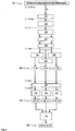
- FIG. 2 shows in a block diagram the evaluation algorithms of the signals 18 in the monitoring plane 12.
- the acceleration channels are read in at a sampling rate that matches the highest frequency of interest in time processing, for example 32 kHz. Then they are digitally filtered and down sampled (step 12). As a result, the frequency band is limited and minimizes the computational effort for the evaluation algorithms.
- the evaluation is done with a Hannig window (step 22) to reduce distortion in the frequency domain.
- the amplitude and phase spectra of the signals are determined by means of a spectral analysis 22.
- FFT Fast Fourier Transformation
- individual spectra are generated overlapping in the time domain, for example with an overlap of 50%, so that the number of individual spectra to be determined is nineteen.
- This process is restarted with a capture clock of 30 s.
- the degree of overlap of the individual spectra can be varied within the limits between 30% and 70%, for example, deviating from the preferably 50%.
- spectral analysis 22 for example, nineteen spectra are available for the channels 16, of which the spectral auto and cross powers are determined by suitable combination (step 30) (step 24) and subsequently averaged (step 26). On the basis of the cross powers, the averaged phase spectra 34 are determined. Averaged coherence spectra 32 are determined on the basis of the auto and cross powers. As a result of this evaluation, there are thus eight features M 1 (corresponding to the coherence spectra 32), eight features M 2 (corresponding to the phase spectra 34) and sixteen features M 3 (corresponding to the amplitude spectra 28) to disposal. Thus, a total of thirty-two features 36 (8 x M 1 + 8 x M 2 + 16 x M 3 ) are available.
- the spectra 28, 32 and 34 are determined over a period of for example 120 s (or optionally 180 s, 240 s, 300 s or 360 s) and stored in between.
- the operating speed v of the machine is measured once at the beginning and once at the end of each 20 s detection window and also buffered.
- the least possible speed change is used as a criterion for a final archiving of a spectrum originating from the set time window.
- a selection circuit 38 can be used to define frequency bands (monitoring bands) to be monitored by defining lower and upper band boundaries within the present amplitude spectra 28. Phase spectra 34 and coherence spectra 32. Within these defined frequency bands, an evaluation is carried out with regard to different parameters. First, the frequency of the maximum (peak) within the frequency band is determined. It is then checked whether the peak lies within the upper and lower frequency limits (parameters 1 and 2). If the peak leaves this frequency range, an alarm bit is set. The amplitude value of the peak must be within the defined amplitude limit (parameters 3 and 4). If the range set by the upper and lower amplitude limits is left, an alarm bit is also set. The amplitude spectrum also monitors the 3dB point.
- This -3dB point appears in the spectrum to the left as well as to the right of the peak.
- the lower and upper frequency limits can be set (parameters 5 to 8). This provides information about the waveform around the peak area. If the 3dB point leaves the area defined by the boundaries, an alarm bit is also set.
- a check 40 of the averaged spectra is thus possible, with only the parameters 1 to 4 being activated for the coherence spectra 32 and the phase spectra 34, while the parameters 1 to 8 are activated for the amplitude spectra 28 ,
- the limit overflow monitor 40 is applied only to the amplitude spectra 28 intended for archival purposes.
- the maximum resulting from the examination of the parameters alarm signals (alarm bits) 42 are a logic logic 44 which links the alarm signals 42 and under conditions fulfilled to an alarm 46, for example, in the set 300s clock, leads.
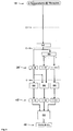
- FIG. 3 shows in a block diagram the evaluation algorithms of the signals 18 in the monitoring plane 14 Acceleration signals of individual components of the machine before.
- the respective four signals of monitored parts of the machine are preferably evaluated, so that eight of the acceleration signals reach the evaluation.
- These are split over a filter (splitter) 48 into two subbands.
- the lower subband 50 goes over a range of, for example, 0 to 400 Hz while the upper subband 52 covers the frequency range of, for example, 0.4 to 16 kHz.
- the mean value and the variance are calculated over a period of 1 s.
- the respective 1-second kurtosis value is then calculated (steps 54 and 56, respectively). These 1-second kurtosis values are then averaged over a period of 30 seconds (steps 58 and 60, respectively).
- M 4 kurtosis values in the low subband
- M 5 kurtosis values in the high subband
- FIG. 4 shows in a block diagram the evaluation algorithms of the signals 18 in the monitoring plane 16.
- the output signals in turn are the sixteen acceleration signals of individual components of the machine in front.
- the determination of a crest factor and for another eight (the same or the other) acceleration signals is a histogram analysis.
- the signals are in turn, as in the previous evaluation algorithms, sampled at a sample rate of 32 kHz.
- the individual values are recorded in 10 ms time windows, that is to say in batches of 320 individual values.
- the peak value and the RMS value are determined in each case and the quotient of the peak value and RMS value (crest factor) is formed.
- the histogram analysis (step 72) is performed for eight acceleration signals, in particular for the four signals of the monitored parts of the machine.
- the detection also takes place in 10 ms time windows, ie in batches of 320 values. From these 320 values per time window, the largest positive and smallest negative value is selected (step 74) and entered into the histogram 76. Thus, two values per 10 ms time window per monitored acceleration signal accumulate. Histogram analysis monitors the frequency of specific acceleration values in four speed classes. A histogram 76 is created for each speed class and signal.
- the crest factor analysis thus provides eight features M 6 and the histogram analysis thirty-two features M 7 .
- a total of forty features 36 "(8 ⁇ M 8 + 32 ⁇ M 7 ) are available in the monitoring level 16.
- the individual features are monitored for exceeding a threshold value.
- the characteristics obtained as a result of the histogram analysis are monitored for exceeding a symmetrical threshold value.
- This symmetrical threshold value can be set as a parameter. Since the speed is recorded in 1s increments, the in these 100x10 ms windows captured values at the same speed class.
- the acceleration values are monitored in size depending on the speed class. If an adjustable maximum value is exceeded, or if the threshold value of the crest factor is exceeded, a signal alarm is present.
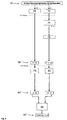
- FIG. 5 shows in a block diagram the evaluation algorithms of the temperature signals which are available in the total quantity of the signals 18.
- the monitoring of the temperatures takes place in the monitoring level 14, since the temperature monitoring, for example, so-called hot runners can be detected, which can arise as a result of bearing damage in the early stages.
- a limit value is the difference of the individual temperature of a bearing and the average temperature of all bearing shells of a machine part, which may also not exceed a certain limit.
- the bearing-specific temperature deviation .DELTA.T determined in the signal processing is monitored for a threshold value that can be set as a parameter.
- the specific maximum temperature T max is programmable as an alarm parameter.
- the check 88 is made as to whether the temperature T individual > T max or the temperature T is individual > T average > ⁇ T limit .
- FIG. 6 shows a block diagram of the entire monitoring system 10 with the evaluation algorithms in the monitoring levels 12, 14 and 16. Overall, the following summarized signal processing or determination of features results. Alarm bits and alarms triggered via logic operations. In detail, these procedures have already been explained with reference to the preceding figures.
- the compilation in FIG. 7 is composed of the already described diagnostic tasks of FIGS. 3 to 6 and once again shows the selected form of the reporting concept via logical links in the three different signal processing scenarios with reaction times adapted to the task.
- the limit value violations are checked in frequency domain monitoring after the spectra have been selected in adjustable time windows (120 or 180/240/300/360 seconds).
- the monitoring is applied to sixteen Acceleration signals and eight coherence and phase combinations per machine, machine area or machine part.
- For the amplitude spectra there are eight monitoring bands and eight parameters (2 x amplitude, 2 x frequency, 4 x attenuation), ie 1024 alarm bits per machine, for the coherence / phase signals (2 x amplitude / 2 x frequency) corresponding to 256 alarm bits per machine available.
- a maximum of eight freely selectable alarm bits can be linked during frequency monitoring and trigger an external alarm after being checked by a timer. The timer ensures that only the result of the combination of two successive stored measurements (spectra determinations) an alarm condition is met, to pass an alarm to the outside.
- the data acquisition and signal alarm check for histogram and crest factor takes place every 10 ms. This procedure is applied to the eight bearing signals of a machine. Forty alarm bits are set per machine.
- kurtosis In direct connection with the bearing vibration monitoring by means of kurtosis is the monitoring of the bearing temperatures. Each storage temperature is checked for two alarm conditions (T max and ⁇ T granule ). Thus, sixteen alarm bits are available per machine. The result of the storage temperature monitoring is also in the 30s time cycle as the kurtosis monitoring, that is, in the linking of kurtosis and temperature alarms no management of different clock cycles is necessary. The detected alarm bits are written to a kurtosis temperature signal alarm file, which is updated every 30 seconds. The signal alarms are linked in the logic editor and lead to alarm when the condition is fulfilled.
- FIG. 7 shows schematically the structure of the monitoring system 10.
- the monitoring system 10 is modular, so that a separate startup (the individual monitoring levels 12, 14 and 16) and a quick replacement of individual components and the possibility of individual adaptation to other conditions is possible .
- the signals 18 of the sensors, not shown, are adapted to the input ranges of analog-to-digital converters 102 via a signal conditioning 100.
- the analog-to-digital converters 102 are implemented according to the required number of channels of the signals to be processed and the conversion rate of 32 samples per second.
- the analog-to-digital converters are connected to a digital signal processor (DSP) 104, in which the signal processing or processing, the feature extraction, the limit comparisons as well as the alarming - in accordance with the explanation of the preceding figures - realized.
- DSP digital signal processor
- the digital signal processor 104 is associated with a flash memory 106 for loading the program and an external memory 108 for storing the data.
- the flow control of the digital signal processor 104 is performed by a computing system 110, which is associated with a flash memory disk 112 for a temporary storage of the measurement data.
- the computer system 110 is assigned a hard disk memory 114. This equipment makes it possible, during the intended use of the machine to write the data while driving on the flash memory 112 and to make a rewriting of the data (copy) on the hard disk memory 114 only when the machine is stopped. As a result, the data security of the monitoring system 10 is increased.
- the size of the flash memory 112 here must be adapted to the maximum runtime of the machine and can be rewritten after each successful dubbing on the hard disk memory 114.
Abstract
Description
Die Erfindung betrifft ein Verfahren und eine Vorrichtung zum Überwachen des Verhaltens von stationären Maschinen und Maschinenanlagen, insbesondere von Kraftwerken und Windkraftanlagen, und der Diagnose von Komponenten von Maschinen und Maschinenanlagen, wobei gleiche und/oder unterschiedliche Betriebsparameter (Messsignale) der Maschine/Maschinenanlage beziehungsweise von Komponenten der Maschine/Maschinenanlage während deren Einsatz erfasst und ausgewertet werden.The invention relates to a method and an apparatus for monitoring the behavior of stationary machines and machinery, in particular of power plants and wind turbines, and the diagnosis of components of machines and machinery, wherein the same and / or different operating parameters (measurement signals) of the machine / machinery or of Components of the machine / machine system are detected and evaluated during their use.
Bekannt ist, das Verhalten von Maschinen während deren bestimmungsgemäßem Einsatz zu überwachen, indem das Verhalten repräsentierende Betriebsparameter der Maschinen erfasst und ausgewertet werden. Unter dem Begriff "Maschine" werden bei dieser Anmeldung Arbeitsmaschinen und Kraftmaschinen sowie Maschinenanlagen mit zu überwachenden Teilen, Komponenten und angeschlossenen Maschinen verstanden.It is known to monitor the behavior of machines during their intended use by detecting and evaluating the operating parameters of the machines representing the behavior. The term "machine" in this application machines and power machines and machinery with monitored parts, components and connected machines understood.
EP 1 022 631 A2 offenbart ein hierarchisches Diagnosesystem einer Produktionsstraße.EP 1 022 631 A2 discloses a hierarchical diagnostic system of a production line.
DE 197 40 974 A1 offenbart ein Buchfertigungssystem umfassend eine Buchfertigungsstraße mit mehreren Fertigungsmaschinen, Sensoren zur Überwachung und Aktoren zur Einstellung von Maschinenparametern, Anzeigevorrichtungen, Eingabevorrichtungen sowie Rechner, mittels der programmgesteuert Auftragsdaten verarbeitet, Einrichtungsmaßnahmen durchgeführt und Maschinenprozesse überwacht werden.DE 197 40 974 A1 discloses a book production system comprising a book production line with a plurality of production machines, sensors for monitoring and actuators for setting machine parameters, display devices, input devices and computers, processed by the program-controlled order data, implemented facility measures and machine processes are monitored.
Die nachveröffentlichte Druckschrift DE 101 63 148 A1 offenbart ein Verfahren und eine Vorrichtung zum Überwachen des Fahrverhaltens von Schienenfahrzeugen und die Diagnose von Komponenten von Schienenfahrzeugen, wobei gleiche und / oder unterschiedliche Betriebsparameter (Messsignale) des Schienenfahrzeuges beziehungsweise von Komponenten des Schienenfahrzeuges während dessen bestimmungsgemäßen Einsatzes erfasst und ausgewertet werden, wobei in Abhängigkeit der Zuordnung zu Überwachungsebenen einer Überwachungshierarchie, zur Erzielung das Fahrverhalten charakterisierender, ereignisabhängiger Aussagen, die Betriebsparameter (Messsignale) wenigstens einer Überwachungsebene zugeführt werden, wobei je nach Zuordnung zu einer der Überwachungsebenen die Betriebsparameter (Messsignale) in den Überwachungsebenen gleichen und/oder unterschiedlichen Auswertealgorithmen unterzogen werden.The subsequently published document DE 101 63 148 A1 discloses a method and a device for monitoring the driving behavior of rail vehicles and the diagnosis of components of rail vehicles, wherein identical and / or different operating parameters (measuring signals) of the rail vehicle or of components of the rail vehicle during its intended use detected and are evaluated, depending on the assignment to monitoring levels of a monitoring hierarchy, to achieve the driving behavior characterizing event-dependent statements, the operating parameters (measurement signals) are fed to at least one monitoring level, depending on the assignment to one of the monitoring levels, the operating parameters (measurement signals) in the monitoring levels identical and / or different evaluation algorithms are subjected.
Aufgrund unvorhergesehener äußerer und/oder innerer Einflüsse kann es zu einer Veränderung des Verhaltens einzelner Komponenten kommen, die dann zu einer entsprechenden Signalauslösung führen. Oftmals sind diese äußeren und inneren Einflüsse nicht identisch mit den eigentlich zu überwachenden Ereignissen, beispielsweise Schäden an einzelnen Komponenten, so dass bei den bekannten Überwachungsverfahren Fehlalarme nicht ausgeschlossen werden können. Aus Gründen der Systemakzeptanz muss jedoch jedem Alarm die maximal mögliche Bedeutung beigemessen werden, so dass hierdurch das Betriebsverhalten der Maschinen entsprechend der Anzahl von Fehlalarmierungen beeinträchtigt istDue to unforeseen external and / or internal influences, there may be a change in the behavior of individual components, which then lead to a corresponding signal triggering. Often, these external and internal influences are not identical to the events actually to be monitored, for example damage to individual components, so that false alarms can not be ruled out in the known monitoring methods. For reasons of system acceptance, however, each alarm must be given the maximum possible significance, so that the operating behavior of the machines is impaired in accordance with the number of false alarms
Der Erfindung liegt die Aufgabe zugrunde, ein Verfahren und eine Vorrichtung der gattungsgemäßen Art zu schaffen, mittels denen eine sichtbare Überwachung des Verhaltens von stationären Maschinen bei minimaler Fehlalarmauslösung möglich ist.The invention has for its object to provide a method and apparatus of the generic type, by means of which a visible monitoring of the behavior of stationary machines with minimal false alarm triggering is possible.
Erfindungsgemäß wird diese Aufgabe durch ein Verfahren mit den im Anspruch 1 und eine Vorrichtung mit den im Anspruch 14 genannten Merkmalen gelöst.According to the invention this object is achieved by a method with the features mentioned in claim 1 and a device with the features mentioned in
Dadurch, dass in Abhängigkeit der Zuordnung zu Überwachungsebenen einer Überwachungshierarchie, zur Erzielung des Verhaltens charakterisierender, ereignisabhängiger Aussagen, die Betriebsparameter (Messsignale) wenigstens einer Überwachungsebene zugeführt werden, wobei je nach Zuordnung zu einer der Überwachungsebenen die Betriebsparameter (Messsignale) in den Überwachungsebenen gleichen und/oder unterschiedlichen Auswertealgorithmen unterzogen werden, ist vorteilhaft möglich, eine optimierte Überwachung und Diagnose der Maschine durchzuführen.Characterized in that depending on the assignment to monitoring levels of a monitoring hierarchy, to achieve the behavior characterizing, event-dependent statements, the operating parameters (measurement signals) are supplied to at least one monitoring level, depending on the assignment to one of the monitoring levels, the operating parameters (measurement signals) in the monitoring levels and / or subjected to different evaluation algorithms, it is advantageously possible to carry out an optimized monitoring and diagnosis of the machine.
Es ist insbesondere möglich, durch die gegebenen Kombinationsmöglichkeiten der Auswahl der einzelnen Betriebsparameter (Messsignale) beziehungsweise der unterschiedlichen Kombinationsmöglichkeiten hinsichtlich der Zuordnung zu den Überwachungsebenen - und damit der Auswahl der Auswertealgorithmen - sich anbahnende Schadensentwicklungen deutlich vor Erreichen kritischer Zustände zu erkennen und somit den sich hieraus ergebenden Zeitgewinn einerseits zur Einleitung von Gegenmaßnahmen und andererseits zur Selbstüberprüfung hinsichtlich des Ausschlusses von Fehlalarmen zu nutzen. In den unterschiedlichen Überwachungsebenen können hierbei gleiche Auswertealgorithmen und/oder unterschiedliche Auswertealgorithmen, beispielsweise im Frequenzbereich und/oder Zeitbereich und/oder im Statistikbereich, zum Einsatz kommen.In particular, it is possible, due to the given combination possibilities of the selection of the individual operating parameters (measurement signals) or of the different possible combinations with regard to the assignment to the monitoring levels - and thus the selection of the evaluation algorithms - to clearly recognize imminent damage developments before reaching critical states and thus resulting from this to gain the time gained on the one hand to initiate countermeasures and on the other hand to self-check with regard to the exclusion of false alarms. In the different monitoring levels, the same evaluation algorithms and / or different evaluation algorithms, for example in the frequency domain and / or time domain and / or in the statistics domain, can be used.
insbesondere ist auch erfindungswesentlich, dass die den unterschiedlichen Betriebsparametern entsprechenden Signale in den unterschiedlichen Überwachungsebenen gegebenenfalls unterschiedlichen Auswertealgorithmen unterworfen werden können. Hierdurch kann eine Anpassung der Auswertung der Signale an die unterschiedlichen Überwachungsebenen in einfacher Weise erfolgen, wobei entsprechend einer notwendigen Reaktionszeit zur Erkennung relevanter Ereignisse entsprechend optimale Auswertealgorithmen herangezogen werden. Es ist insbesondere auch möglich, wenigstens zwei Betriebsparameter (Messsignale), die gleich oder unterschiedlich sein können, innerhalb einer Überwachungsebene miteinander zu verknüpfen.In particular, it is also essential to the invention that the signals corresponding to the different operating parameters in the different monitoring levels can optionally be subjected to different evaluation algorithms. In this way, an adaptation of the evaluation of the signals to the different monitoring levels can be carried out in a simple manner, corresponding to an appropriate reaction time for the detection of relevant events correspondingly optimal evaluation algorithms are used. In particular, it is also possible to link at least two operating parameters (measuring signals), which may be the same or different, within a monitoring level.
Bevorzugte Ausgestaltungen der Erfindung ergeben sich aus den in den Unteransprüchen genannten Merkmalen.Preferred embodiments of the invention will become apparent from the features mentioned in the dependent claims.
Die Erfindung wird nachfolgend an Ausführungsbeispielen anhand der zugehörigen Zeichnungen näher erläutert. Es zeigen:
- Figur 1
- schematisch ein Überwachungssystem einer Maschine;
Figuren 2 bis 5- Blockschaltbilder der Signalverarbeitung innerhalb einzelner Überwachungsebenen des Überwachungssystems;
Figur 6- ein Gesamtblockschaltbild der Signalverarbeitungspfade und
- Figur 7
- schematisch den Datenfluss im Überwachungssystem
- FIG. 1
- schematically a monitoring system of a machine;
- FIGS. 2 to 5
- Block diagrams of the signal processing within individual monitoring levels of the monitoring system;
- FIG. 6
- an overall block diagram of the signal processing paths and
- FIG. 7
- schematically the data flow in the monitoring system
Figur 1 zeigt schematisch ein Überwachungssystem 10 für eine Maschine.
Bei der M.= Maschine kann es sich beispielsweise um eine Arbeitsmaschine oder um eine Kraftmaschine wie einen Motor oder eine Turbine insbesondere eines Kraftwerkes oder einer Windkraftanlage handeln.FIG. 1 shows schematically a
The M. = machine may be, for example, a work machine or an engine such as a motor or a turbine, in particular a power plant or a wind turbine.
Das Überwachungssystem 10 umfasst drei Überwachungsebenen 12, 14, und 16. Die Überwachungsebenen 12, 14 und 16 bauen hierarchisch aufeinander auf. Die erste Überwachungsebene 12 beinhaltet allgemeine Diagnosen zur Erfassung von Schäden, Fehlern oder dergleichen im Anfangsstadium, die im Rahmen von Wartungen, Reparaturen und/oder Instandhaltungen zeitlich unkritisch behoben werden können.The
In der Überwachungsebene 14 werden fortgeschrittene Schäden und/oder Fehler erkannt, die gegebenenfalls zu gefährlichen Situationen führen können.At
Die Überwachungsebene 16 beinhaltet einen sogenannten Aggregateschutz, der beispielsweise das Festlaufen eines Lagers erkennt, wobei hierbei der Extremfall, d.h. z. B. der Crash einer Maschine, eingeschlossen ist.The
Dem Überwachungssystem 10 werden hier insgesamt mit 18 bezeichnete Signale zur Verfügung gestellt. Die Signale 18 werden unter anderem von an einzelnen Komponenten der Maschine angeordneten Sensoren geliefert.
Die Signale 18 umfassen femer eine Ist-Drehzahl der Maschine, eine Laufleistung der Maschine und Temperatursignale, die z.B. proportional gemessene Lagertemperaturen sind. Gegebenenfalls können dem Überwachungssystem auch weitere physikalische Größen, die Betriebsparameter der Maschine charakterisieren, zugeführt werden. Die Signale 18 stellen somit allesamt momentane dynamische Messgrößen der überwachten Maschine dar.The
The
In jeder Überwachungsebene 12, 14 und 16 werden die dem Überwachungssystem 10 zugeführten Signale 18 unterschiedlichen Auswertealgorithmen unterzogen. Dies betrifft sowohl die Art der Auswertung als auch die Zeitspanne der Auswertung. Hierauf wird im Einzelnen anhand der nachfolgenden Figuren noch näher eingegangen. Die Auswertung der Signale 18 erfolgt dahingehend, ob den Überwachungsebenen 12, 14 oder 16 zuzuordnende Ereignisse erkannt werden. In der unkritischsten Überwachungsebene 12 ist beispielsweise eine Verarbeitungszeit bis zu einer Zeitspanne t1 von beispielsweise 300 s vorgesehen. Bei Erkennen eines relevanten Ereignisses in der Überwachungsebene 12, erfolgt eine Meldung 12' an die Instandhaltung oder dergleichen. Die Meldung 12' kann beispielsweise mittels Datenfernübertragung abgesetzt werden.In each
In der Überwachungsebene 14 erfolgt die Bearbeitung der Signale 18 mit einer Verarbeitungszeitspanne t2, die beispielsweise bis 30 s beträgt. Aufgrund der der Überwachungsebene 14 zuzuordnenden kritischeren Schadensentwicklung ist hier die Verarbeitungszeit schneller. Bei Erkennen eines der Übeniwachungsebene 14 zuzuordnenden Ereignisses erfolgt eine Meldung 14', die beispielsweise bis 0,1 s beträgt. Wird ein der Überwachungsebene 16 zuzuordnendes Ereignis erkannt, erfolgt eine Meldung 16', die direkt oder indirekt einen Eingriff in den Betrieb der Maschine, beispielsweise ein Abschalten oder dergleichen, auslöst.In the
Es wird deutlich, dass aufgrund unterschiedlicher Schadenseskalationsgrade entsprechend der Überwachungsebenen 12, 14, 16 gestaffelte Meldungen 12', 14' beziehungweise 16' vorgesehen sind. Während die der Überwachungsebene 12 zuzuordnenden Ereignisse zeitlich unkritisch sind, führen der Überwachungsebene 14 zuzuordnende Ereignisse unmittelbar zu Meldungen an ein internes Kommunikationsnetz mit eventuellen Vorschlägen für durch das Personal einzuleitende Gegenmaßnahmen. Die Meldungen 16' hingegen lösen sofortige Gegenmaßnahmen aus.It becomes clear that staggered messages 12 ', 14' are provided in relation to 16 'due to different levels of damage escalation corresponding to the
Dem Überwachungssystem 10 werden noch Steuer- beziehungsweise Führungsgrößen zugeführt, die beispielsweise eine Mindestarbeitsgeschwindigkeit vmin der Maschine und ein Verknüpfungsalgorithmus 20 (Verknüpfungslogiken 44, 68, 82, Figuren 2 bis 6) der Signale 18 entsprechend der Verarbeitung der Signale in den einzelnen Überwachungsebenen 12, 14 beziehungsweise 16 vorgeben.The
Hinsichtlich der in den einzelnen Überwachungsebenen 12, 14 und 16 anzuwendenden Auswertealgorithmen ist Folgendes festzuhalten. In der Überwachungsebene 12 zur Einleitung von Wartungsmaßnahmen sind Verfahren im Frequenzbereich zielführend. Diese besitzen aufgrund der durch Mittelungsprozeduren verbesserten Signalstatistik das Potential, Eigenfrequenzen von Teilen der Maschine und der Maschine selber im Betrieb zu verfolgen und schädigungs- oder verschleißbedingte Veränderungen frühzeitig zu erkennen. Die von außen herrührenden Anregungseinflüsse stören dabei die Erkennung und Beurteilung der Frequenzlage nicht.With regard to the evaluation algorithms to be applied in the
Für die Erkennung von gefährlichen Situationen in der Überwachungsebene 14 werden beispielsweise statistische Verfahren eingesetzt, die insbesondere bei periodisch auftretenden Stoßimpulsen Aussagen zu Fehlern liefern. Mittels dieser Auswertealgorithmen können eskalierende Entwicklungen kurzfristig erkannt werden, um entsprechende Gegenmaßnahmen einzuleiten (Meldung 14').For the detection of dangerous situations in the
Die in der Überwachungsebene 16 eingesetzten Auswertealgorithmen sind in der Lage, spontan eintretende Ausfälle zu detektieren. Hierbei werden Zeitreihenanalysen (Histogrammanalysen) in verschiedenen Arbeitsgeschwindigkeitsklassen durchgeführt.The evaluation algorithms used in the
Figur 2 zeigt in einem Blockschaltbild die Auswertealgorithmen der Signale 18 in der Überwachungsebene 12. Als Ausgangssignale liegen sechszehn Beschleunigungssignale einzelner Komponenten der Maschine vor. Dies können beispielsweise Beschleunigungssignale oder dergleichen sein. Die Beschleunigungskanäle werden mit einer Abtastrate eingelesen, die an die höchste interessierende Frequenz bei der Zeitverarbeitung angepasst ist, zum Beispiel 32 kHz. Anschließend werden sie digital gefiltert und downgesampelt (Schritt 12). Hierdurch wird das Frequenzband begrenzt und der Rechenaufwand für die Auswertealgorithmen minimiert. Anschließend erfolgt die Bewertung mit einem Hannig-Fenster (Schritt 22), um Verzerrrungen im Frequenzbereich zu reduzieren. Anschließend werden mittels einer Spektralanalyse 22 die Amplituden- und Phasenspektren der Signale ermittelt. Dies erfolgt beispielsweise mittels einer Fast-Fourier-Transformation (FFT) mit einer Auflösung von 0.5 Hz. Dies führt bei einem interessierenden Frequenzbereich von 0 bis 1024 Hz zu 4096 erforderlichen Stützstellen für die Fast-Fourier-Transformation, so dass sich ein Erfassungsfenster von 2 s (4096 Stützstellen durch fsample = 2 s) für eine Einzel-Fast-Fourier- Tranformation ergibt. Über einen Zeitraum von 20 s werden Einzelspektren im Zeitbereich überlappend generiert, beispielsweise mit einem Überlappungsgrad von 50%, so dass die Anzahl der zu ermittelnden Einzelspektren neunzehn beträgt. Dieser Vorgang wird mit einem Erfassungstakt von 30 s neu gestartet. Der Überlappungsgrad der Einzelspektren kann hierbei, beispielsweise abweichend von den vorzugsweise 50%, in den Grenzen zwischen 30% bis 70% variiert werden. Im Ergebnis der Spektralanalyse 22 stehen für die Kanäle 16 jeweils zum Beispiel neunzehn Spektren zur Verfügung, von denen durch geeignete Kombination (Schritt 30) die spektralen Auto- und Kreuzleistungen bestimmt (Schritt 24) und anschließend gemittelt (Schritt 26) werden. Auf Basis der Kreuzleistungen werden die gemittelten Phasenspektren 34 bestimmt. Auf Basis der Auto- und Kreuzleistungen werden gemittelte Kohärenzspektren 32 bestimmt Im Ergebnis dieser Auswertung stehen somit acht Merkmale M1 (entspricht den Kohärenzspektren 32), acht Merkmale M2 (entspricht den Phasenspektren 34) und sechszehn Merkmale M3 (entspricht den Amplitudenspektren 28) zur Verfügung. Somit stehen insgesamt zweiunddreißig Merkmale 36 (8 x M1 + 8 x M2 + 16 x M3) zur Verfügung.FIG. 2 shows in a block diagram the evaluation algorithms of the
Die Spektren 28, 32 und 34 werden über einen Zeitraum von beispielsweise 120 s (oder wahlweise 180 s, 240 s, 300 s oder 360 s) ermittelt und zwischendurch gespeichert. Die Arbeitsgeschwindigkeit v der Maschine wird einmal zu Beginn und einmal zum Ende eines jeden 20 s-Erfassungsfensters gemessen und ebenfalls zwischengespeichert. Eine möglichst geringe Geschwindigkeitsveränderung wird als Kriterium für eine endgültige Archivierung eines aus dem eingestellten Zeitfenster stammenden Spektrums verwendet.The
Über eine Auswahlschaltung 38 können innerhalb der vorliegenden Amplitudenspektren 28. Phasenspektren 34 und Kohärenzspektren 32 durch Definition unterer und oberer Bandgrenzen zu überwachende Frequenzbänder (Überwachungsbänder) definiert werden. Innerhalb dieser definierten Frequenzbänder erfolgt eine Auswertung hinsichtlich verschiedener Parameter. Zunächst wird die Frequenz des Maximums (Peak) innerhalb des Frequenzbandes ermittelt. Anschließend wird geprüft, ob der Peak innerhalb der oberen und unteren Frequenzgrenze liegt (Parameter 1 und 2). Verlässt der Peak diesen Frequenzbereich, so wird ein Alarmbit gesetzt. Der Amplitudenwert des Peaks muss innerhalb der definierten Amplitudengrenze liegen (Parameter 3 und 4). Wird der durch die obere und die untere Amplitudengrenze eingestellte Bereich verlassen, so wird ebenfalls ein Alarmbit gesetzt. Im Amplitudenspektrum wird auch der-3dB-Punkt überwacht. Dies ist die Frequenzlinie, die in ihrer Amplitude um 3 dB über dem Peak gedämpft ist. Dieser -3dB-Punkt tritt im Spektrum sowohl links als auch rechts vom Peak auf. Für beide 3dB-Punkte lassen sich die untere und die obere Frequenzgrenze einstellen (Parameter 5 bis 8). Hierdurch wird eine Aussage über die Kurvenform rund um den Peak-Bereich gewonnen. Verlässt der 3dB-Punkt den durch die Grenzen definierten Bereich, so wird ebenfalls ein Alarmbit gesetzt.A
Wie dem Blockschaltbild in Figur 2 zu entnehmen ist, ist somit eine Überprüfung 40 der gemittelten Spektren möglich, wobei für die Kohärenzspektren 32 und die Phasenspektren 34 lediglich die Parameter 1 bis 4 aktiviert sind, während für die Amplitudenspektren 28 die Parameter 1 bis 8 aktiviert sind. Die Überwachung 40 auf Grenzwertüberschreitung wird nur auf die für die Archivierung vorgesehenen Amplitudenspektren 28 angewandt. Die aus der Überprüfung der Parameter maximal resultierenden Alarmsignale (Alarmbits) 42 (256 Alarmsignale A1, 256 Alarmsignale A2, 1024 Alarmsignale A3) werden einer Verknüpfungslogik 44 zugeführt, die die Alarmsignale 42 miteinander verknüpft und bei erfüllten Bedingungen zu einer Alarmgebung 46, beispielsweise im eingestellten 300s-Takt, führt.As can be seen from the block diagram in FIG. 2, a
Es wird deutlich, dass bei den in der Überwachungsebene 12 zum Ansatz kommenden Auswertealgorithmen insbesondere Spektralanalysen und Korrelationen eingesetzt sind.It becomes clear that spectral analyzes and correlations are used in particular for the evaluation algorithms used in the
Figur 3 zeigt in einem Blockschaltbild die Auswertealgorithmen der Signale 18 in der Überwachungsebene 14. Als Ausgangssignale liegen wiederum die Beschleunigungssignale einzelner Komponenten der Maschine vor. Hierbei werden vorzugsweise die jeweils vier Signale von überwachten Teilen der Maschine ausgewertet, so dass acht der Beschleunigungssignale 18 zur Auswertung gelangen. Diese werden über einen Filter (Splitter) 48 in zwei Subbänder aufgespalten. Das untere Subband (low) 50 geht über einen Bereich von zum Beispiel 0 bis 400 Hz während das obere Subband (high) 52 den Frequenzbereich von zum Beispiel 0,4 bis 16 kHz abdeckt. Von den in den jeweiligen Subbandern 50 und 52 liegenden Samples wird über eine Zeitspanne von 1 s der Mittelwert und die Varianz (Schritte 51 beziehungsweise 53) berechnet. Hieraus wird dann der jeweilige 1-Sekunden-Kurtosiswert errechnet (Schritte 54 beziehungsweise 56). Diese 1-Sekunden-Kurtosiswerte werden über eine Zeitspanne von 30 s anschließend gemittelt (Schritte 58 beziehungsweise 60). Im Ergebnis dieser Auswertung stehen somit acht Merkmale M4 (Kurtosiswerte im Low-Subband) und acht Merkmale M5 (Kurtosiswerte im High-Subband) zur Verfügung. Somit stehen hier weitere sechzehn Merkmale 36' (8 x M4 + 8 x M5) zur Verfügung.FIG. 3 shows in a block diagram the evaluation algorithms of the
Anschließend erfolgt für jeden der gemittelten Kurtosiswerte eine Überprüfung auf das Überschreiten von Grenzwerten (Schritt 62 beziehungsweise 66). Überschreitet einer der Kurtosiswerte den vorgebbaren Grenzwert, kann jeweils ein Alarmbit 42' generiert werden. Somit stehen hier acht Alarmsignale A4 und acht Alarmsignale A5 zur Verfügung. Diese werden über eine Verknüpfungslogik 68 geführt, die die Alarmsignale 42' miteinander verknüpft und bei erfüllten Bedingungen zu einer Alarmgebung 46', beispielsweise im eingestellten 30s-Takt, führt.Subsequently, for each of the averaged kurtosis values, a check is made for the exceeding of limit values (
Es wird deutlich, dass bei den in der Überwachungsebene 14 zum Ansatz kommenden Auswertealgorithmen insbesondere statistische Verfahren, wie beispielsweise Kurtosis, zur Anwendung kommen.It becomes clear that, in particular, statistical methods such as kurtosis are used for the evaluation algorithms used in the monitoring level.
Figur 4 zeigt in einem Blockschaltbild die Auswertealgorithmen der Signale 18 in der Überwachungsebene 16. Als Ausgangssignale liegen wiederum die sechzehn Beschleunigungssignale einzelner Komponenten der Maschine vor. Für acht dieser Beschteunigungssignale erfolgt die Ermittlung eines Crestfaktors und für weitere acht (die gleichen oder die anderen) Beschleunigungssignale eine Histogrammanalyse. Die Signale sind wiederum, wie bei den vorhergehenden Auswertealgorithmen, mit einer Samplefrequenz von 32 kHz gesampelt.FIG. 4 shows in a block diagram the evaluation algorithms of the
Bei der Ermittlung des Crestfaktors (Schritt 70) erfolgt die Erfassung der Einzelwerte in 10ms-Zeitfenstern, das heißt in Schüben von 320 Einzelwerten. In diesem Zeitfenster wird jeweils der betragsmäßige Spitzenwert und der RMS-Wert ermittelt und der Quotient aus Spitzenwert und RMS-Wert (Crestfaktor) gebildet. Im Ergebnis dieser Auswertung stehen somit acht Merkmale M6 (entspricht den Crestfaktoren) zur Verfügung.When determining the crest factor (step 70), the individual values are recorded in 10 ms time windows, that is to say in batches of 320 individual values. In this time window, the peak value and the RMS value are determined in each case and the quotient of the peak value and RMS value (crest factor) is formed. As a result of this evaluation, there are thus eight features M 6 (corresponding to the crest factors).
Parallel erfolgt die Histogrammanalyse (Schritt 72) für acht Beschleunigungssignale, insbesondere für die jeweils vier Signale der überwachten Teile der Maschine. Die Erfassung erfolgt ebenfalls in 10ms-Zeitfenstern, das heißt in Schüben von 320 Werten. Aus diesen 320 Werten pro Zeitfenster wird der größte positive und kleinste negative Wert selektiert (Schritt 74) und in das Histogramm 76 eingetragen. Somit fallen pro 10ms-Zeitfenster je überwachtem Beschleunigungssignal zwei Werte an. Bei der Histogrammanalyse wird die Häufigkeit von bestimmten Beschleunigungswerten in vier Geschwindigkeitsklassen überwacht. Pro Geschwindigkeitsklasse und Signal wird ein Histogramm 76 erstellt.In parallel, the histogram analysis (step 72) is performed for eight acceleration signals, in particular for the four signals of the monitored parts of the machine. The detection also takes place in 10 ms time windows, ie in batches of 320 values. From these 320 values per time window, the largest positive and smallest negative value is selected (step 74) and entered into the
Durch die Crestfaktoranalyse stehen somit acht Merkmale M6 und durch die Histogrammanalyse zweiunddreißig Merkmale M7 zur Verfügung. Somit stehen in der Überwachungsebene 16 insgesamt vierzig Merkmale 36" (8 x M8 + 32 x M7) zur Verfügung.The crest factor analysis thus provides eight features M 6 and the histogram analysis thirty-two features M 7 . Thus, a total of forty
Die einzelnen Merkmale werden auf Überschreitung eines Schwellwertes überwacht. Die infolge der Histogrammanalyse erzielten Merkmale werden auf das Überschreiten eines symmetrischen Schwellwertes überwacht. Dieser symmetrische Schwellwert ist als Parameter einstellbar. Da die Erfassung der Geschwindigkeit in 1s-Schritten erfolgt, gehören jeweils die in diesen 100x10ms-Zeitfenstern erfassten Werte zur gleichen Geschwindigkeitsklasse. Die Beschleunigungswerte werden geschwindigkeitsklassenabhängig in ihrer Größe überwacht. Wird ein einstellbarer Maximalwert überschritten, beziehungsweise wird der Schwellwert des Crestfaktors überschritten, liegt ein Signalalarm vor. Die aus dieser Überprüfung 78 beziehungsweise 80 maximal resultierenden Alarmsignale (Alarmbits) 42" (acht Alarmsignale A6, zweiunddreißig Alarmsignale A7) werden einer Verknüpfungslogik 82 zugeführt, die die Alarmsignale 42" miteinander verknüpft und bei erfüllten Bedingungen zu einer Alarmgebung 46", beispielsweise im eingestellten 10ms-Takt, führt.The individual features are monitored for exceeding a threshold value. The characteristics obtained as a result of the histogram analysis are monitored for exceeding a symmetrical threshold value. This symmetrical threshold value can be set as a parameter. Since the speed is recorded in 1s increments, the in these 100x10 ms windows captured values at the same speed class. The acceleration values are monitored in size depending on the speed class. If an adjustable maximum value is exceeded, or if the threshold value of the crest factor is exceeded, a signal alarm is present. The maximum resulting from this
Es wird deutlich, dass bei den in der Überwachungsebene 16 zum Ansatz kommenden Auswertealgorithmen insbesondere Crestfaktorbeziehungsweise Histogrammanalysen eingesetzt sind.It becomes clear that crest factor or histogram analyzes are used in particular for the evaluation algorithms used in the
Figur 5 zeigt in einem Blockschaltbild die Auswertealgorithmen der Temperatursignale, die in der Gesamtmenge der Signale 18 zur Verfügung stehen. Die Überwachung der Temperaturen erfolgt in der Überwachungsebene 14, da über die Temperaturüberwachung zum Beispiel so genannte Heißläufer erkannt werden können, die infolge von Lagerschädigungen im Frühstadium entstehen können.FIG. 5 shows in a block diagram the evaluation algorithms of the temperature signals which are available in the total quantity of the
Die der gemessenen Temperatur der einzelnen Lagerhalbschalen entsprechenden Temperatursignale werden in 1s-Schritten erfasst und in einem Zeitfenster von 30 s gemittelt (Schritt 84). Diese somit zur Verfügung stehenden acht gemittelten Temperaturwerte bilden die Merkmale M8. Ferner werden Differenzen (Schritt 86) zwischen den gemittelten Temperatursignalen eines Lagerbereichs oder einer Lagergruppe und der jeweiligen Temperatur einer einzelnen Lagerhalbschale ermittelt, so dass weitere vier Merkmale M9 und weitere vier Merkmale M10 jeweils einer Grenztemperatur ΔT = Tindividuell - Tmittel entsprechend zur Verfügung stehen. Somit stehen insgesamt weitere sechzehn Merkmale 36' in der Überwachungsebene 14 zur Verfügung.The temperature signals corresponding to the measured temperature of the individual bearing half-shells are recorded in 1 s steps and averaged over a time window of 30 s (step 84). These eight averaged temperature values thus available form the features M 8 . Furthermore, differences (step 86) between the averaged temperature signals of a storage area or a storage group and the respective temperature of a single storage half-shell are determined, so that a further four characteristics M 9 and further four features M 10 each have a limit temperature ΔT = T individual - T means corresponding to To be available. Thus, a total of sixteen additional features 36 'in the
Die Merkmale 36' werden anschließend auf eine Grenzwertüberschreitung einer maschinenspezifisch vorgebbaren Maximaltemperatur geprüft. Als weiteres Überwachungskriterium dient die Differenz der Individualtemperatur eines Lagers und der gemittelten Temperatur aller Lagerhalbschalen eines Maschinenteiles, die ebenfalls einen bestimmten Grenzwert nicht überschreiten darf. Die in der Signalverarbeitung ermittelte lagerspezifische Temperaturabweichung ΔT wird auf einen Schwellwert überwacht, der als Parameter einstellbar ist. Ferner ist die spezifische Maximaltemperatur Tmax als Alarmparameter programmierbar. Entspechend dieser vorgebbaren Schwellwerte erfolgt die Überprüfung 88 dahingehend, ob die Temperatur Tindividuell > Tmax oder die Temperatur Tindividuell > Tmittel > ΔTgrenz ist. Die aus der Überprüfung der Parameter maximal resultierenden Alarmsignale 42' (acht Alarmsignale A8, vier Alarmsignale A9, vier Alarmsignale A10) werden der Verknüpfungslogik 68 zugeführt, die die Alarmsignale miteinander verknüpft und bei erfüllten Bedingungen zu einer Alarmgebung 46, beispielsweise im eingestellten 30s-Takt, führtThe features 36 'are then tested for a limit value exceeding a machine-specific predetermined maximum temperature. As a further monitoring criterion is the difference of the individual temperature of a bearing and the average temperature of all bearing shells of a machine part, which may also not exceed a certain limit. The bearing-specific temperature deviation .DELTA.T determined in the signal processing is monitored for a threshold value that can be set as a parameter. Furthermore, the specific maximum temperature T max is programmable as an alarm parameter. As a result of these predefinable threshold values, the
Figur 6 zeigt in einem Blockschaltbild das gesamte Überwachungssystem 10 mit den Auswertealgorithmen in den Überwachungsebenen 12, 14 und 16. Insgesamt ergibt sich somit folgende zusammengefasste Signalverarbeitung beziehungsweise Ermittlung von Merkmalen. Alarmbits und über die Verknüpfungslogiken ausgelöste Alarme. Im Einzelnen sind diese Vorgehensweisen bereits anhand der vorhergehenden Figuren erläutert worden.
Die Zusammenstellung in Figur 7 setzt sich aus den bereits beschriebenen Diagnoseaufgaben der Figuren 3 bis 6 zusammen und zeigt nochmals die gewählte Form des Meldekonzepts über logische Verknüpfungen in den drei unterschiedlichen Signalverarbeitungs-Szenarien mit an die Aufgabenstellung angepassten Reaktionszeiten.FIG. 6 shows a block diagram of the
The compilation in FIG. 7 is composed of the already described diagnostic tasks of FIGS. 3 to 6 and once again shows the selected form of the reporting concept via logical links in the three different signal processing scenarios with reaction times adapted to the task.
Die Überprüfung auf Grenzwertverletzungen erfolgt bei der Frequenzbereichsüberwachung nach erfolgter Spektrenselektion in einstellbaren Zeitfenstern (120 beziehungsweise 180/240/300/360 Sekunden). Angewandt wird die Überwachung auf sechzehn Beschleunigungssignale sowie acht Kohärenz- und Phasenkombinationen je Maschine, Maschinenbereich oder Maschinenteil. Bei den Amplitudenspektren sind acht Überwachungsbänder und acht Parameter (2 x Amplitude, 2 x Frequenz, 4 x Dämpfung), das heißt 1024 Alarmbits pro Maschine, bei den Kohärenz-/Phasensignalen (2 x Amplitude / 2 x Frequenz) entsprechend 256 Alarmbits pro Maschine vorhanden. Maximal können bei der Frequenzüberwachung acht frei wählbare Alarmbits verknüpft werden und lösen nach Abprüfung durch ein Zeitglied eine externe Alarmgebung aus. Das Zeitglied stellt sicher, dass nur Ober das Verknüpfungsergebnis zweier aufeinander folgender abgespeicherter Messungen (Spektrenermittlungen) eine Alarmbedingung erfüllt ist, um einen Alarm nach extern weiterzugeben.The limit value violations are checked in frequency domain monitoring after the spectra have been selected in adjustable time windows (120 or 180/240/300/360 seconds). The monitoring is applied to sixteen Acceleration signals and eight coherence and phase combinations per machine, machine area or machine part. For the amplitude spectra, there are eight monitoring bands and eight parameters (2 x amplitude, 2 x frequency, 4 x attenuation),
Bei der Messdatenerfassung im Zeitbereich erfolgt die Datenerfassung und Signalalarmüberprüfung für Histogramm und Crestfaktor alle 10 ms. Angewandt wird diese Vorgehensweise auf die acht Lagersignale einer Maschine. Pro Maschine werden vierzig Alarmbits gesetzt.For data acquisition in the time domain, the data acquisition and signal alarm check for histogram and crest factor takes place every 10 ms. This procedure is applied to the eight bearing signals of a machine. Forty alarm bits are set per machine.
Bei der Kurtosisüberwachung stehen alle 30 Sekunden neue Wertepaare zur Überwachung bereit. Bei Anwendung auf die beiden Frequenzbereiche (high/low) der acht Lagersignale einer Maschine stehen sechzehn Alarmbits zur Verfügung.With kurtosis monitoring, new value pairs are available for monitoring every 30 seconds. When applied to the two frequency ranges (high / low) of the eight bearing signals of a machine, sixteen alarm bits are available.
Im direkten Zusammenhang mit der Lagerschwingungsüberwachung mittels Kurtosis steht die Überwachung der Lagertemperaturen. Jede Lagertemperatur wir auf zwei Alarmbedingungen hin abgeprüft (Tmax und ΔTgranze). Somit stehen pro Maschine sechzehn Alarmbits zur Verfügung. Das Ergebnis der Lagertemperaturüberwachung liegt dabei ebenfalls im 30s-Zeittakt wie die Kurtosisüberwachung vor, das heißt, bei der Verknüpfung von Kurtosis und Temperaturalarmen wird keine Verwaltung unterschiedlicher Zeittakte notwendig. Die ermittelten Alarmbits werden in ein Kurtosis-Temperatur-Signalalarmfile geschrieben, welches alle 30 Sekunden aktualisiert wird. Die Signalalarme werden im Logikeditor verknüpft und führen bei erfüllter Bedingung zur Alarmgebung.In direct connection with the bearing vibration monitoring by means of kurtosis is the monitoring of the bearing temperatures. Each storage temperature is checked for two alarm conditions (T max and ΔT granule ). Thus, sixteen alarm bits are available per machine. The result of the storage temperature monitoring is also in the 30s time cycle as the kurtosis monitoring, that is, in the linking of kurtosis and temperature alarms no management of different clock cycles is necessary. The detected alarm bits are written to a kurtosis temperature signal alarm file, which is updated every 30 seconds. The signal alarms are linked in the logic editor and lead to alarm when the condition is fulfilled.
Figur 7 zeigt schematisch den Aufbau des Überwachungssystems 10. Das Überwachungssystem 10 ist modular aufgebaut, so dass eine separate Inbetriebnahme (der einzelnen Überwachungsebenen 12, 14 und 16) sowie ein schneller Austausch einzelner der Komponenten sowie die Möglichkeit einer individuellen Anpassung an andere Bedingungen möglich ist. Die Signale 18 der nicht dargestellten Sensoren werden über eine Signalkonditionierung 100 an die Eingangsbereiche von Analog/Digital-Umsetzern 102 angepasst. Die Analog/Digital-Umsetzer 102 sind entsprechend der erforderlichen Kanalanzahl der zu verarbeitenden Signale und der Umsetzrate von 32 Samples pro Sekunde realisiert. Die Analog/Digital-Umsetzer sind an einen digitalen Signalprozessor (DSP) 104 angeschlossen, in dem die Signalverarbeitung beziehungsweise - bearbeitung, die Merkmalsextraktion, die Grenzwertevergleiche sowie die Alarmgebung - entsprechend der Erläuterung zu den vorhergehenden Figuren - realisiert ist. Dem digitalen Signalprozessor 104 ist ein Flash-Speicher 106 zum Laden des Programmes und ein externer Speicher 108 zum Ablegen der Daten zugeordnet. Die Ablaufsteuerung des digitalen Signalprozessors 104 erfolgt durch ein Rechensystem 110, dem für eine temporäre Speicherung der Messdaten eine Flash-Speicherdisc 112 zugeordnet ist. Ferner ist dem Rechensystem 110 ein Festplattenspeicher 114 zugeordnet. Durch diese Ausstattung wird ermöglicht, während des bestimmungsgemäßen Einsatzes der Maschine die Daten während der Fahrt auf den Flash-Speicher 112 zu schreiben und erst im Stillstand der Maschine eine Umschreibung der Daten (Kopieren) auf den Festplattenspeicher 114 vorzunehmen. Hierdurch wird die Datensicherheit des Überwachungssystems 10 erhöht. Die Größe des Flash-Speichers 112 muss hierbei der maximalen Laufzeit der Maschine angepasst sein und kann nach jedem erfolgten Überspielen auf den Festplattenspeicher 114 neu beschrieben werden.Figure 7 shows schematically the structure of the
Es wird deutlich, dass durch die Systemlösung ein sicherer Betrieb des Überwachungssystems 10 unter Einhaltung erhöhter Anforderungen an Robustheit, Stabilität und Energieeffizienz möglich ist.It becomes clear that the system solution enables safe operation of the
Claims (14)
- Method for monitoring the behaviour of stationary machines and machine installations, in particular that of power stations and wind power stations, and for the diagnosis of components of machines and machine installations, wherein the same and/or different operating parameters of the machine/machine installation or of components of the machine/machine installation are recorded and evaluated during their use, characterised in that the operating parameters of at least one monitoring level are assigned to a monitoring hierarchy, dependent on the assignment to monitoring levels (12, 14, 16), so that event-dependent statements characterising the behaviour can be made, wherein, according to the assignment to one of the monitoring levels (12, 14, 16) the operating parameters at the monitoring levels (12, 14, 16) are subjected to the same and/or different evaluation algorithms, wherein, at a first monitoring level (12), the signals corresponding to the operating parameters are subjected to frequency evaluation processes, in particular spectral analyses, correlations or the like, and at a second monitoring level (14) the signals corresponding to the operating parameters are subjected to statistical evaluation processes, in particular Kurtosis value determinations, and wherein at the monitoring levels assigned messages (12', 14', 16') or actions are generated.
- Method according to Claim 1, characterised in that at least two operating parameters, which may be the same or different, are interlinked within one monitoring level.
- Method according to one of the preceding claims, characterised in that three monitoring levels (12, 14, 16) are provided.
- Method according to one of the preceding claims, characterised in that at the first monitoring level (12) general diagnoses are carried out to record damage, faults or the like.
- Method according to one of the preceding claims, characterised in that at the second monitoring level (14) progressive damage, faults or the like leading to failures and/or defective productions can be detected.
- Method according to one of the preceding claims, characterised in that at the third monitoring level (16) an aggregate protection is provided.
- Method according to Claim 6, characterised in that at the monitoring level (16) the signals corresponding to the operating parameters are subjected to time evaluation processes, in particular crest factor and histogram analysis.
- Method according to one of the preceding claims, characterised in that acceleration signals of components of the machines/machine installation, temperature signals of components of the machine/machine installation, an actual sped signal of the machine/machine installation and a performance of the machine/machine installation are recorded as operating parameters.
- Method according to one of the preceding claims, characterised in that the operating parameters at the different monitoring levels are evaluated on the basis of a different period of time.
- Method according to one of the preceding claims, characterised in that all error signals occurring at one monitoring level (12, 14, 16) are each assigned to a gate logic (44, 68, 82) for obtaining alarm messages (12', 14', 16').
- Method according to one of the preceding claims, characterised in that a minimum speed of the machine/machine installation acts as a guide value.
- Method according to one of the preceding claims, characterised in that the signals, the evaluations and/or the messages are stored over an optional length of time.
- Method according to Claim 12, characterised in that the data are stored in an intermediate memory during the operation of the machine/machine installation, and in that the data are rewritten on a fixed-disc device whilst the machine/machine installation is stationary.
- Device for monitoring the behaviour of stationary machines/machine installations and for diagnosing components of machines/machine installations, for carrying out the process according to one of the preceding claims, with first means for recording operating parameters of the machine/machine installation or of components of the machine/machine installation, characterised by second means for assigning the operating parameters to different monitoring levels (12, 14, 16) of a monitoring system (10), wherein the operating parameters are assigned to at least one monitoring level, depending on the assignment to monitoring levels (12, 14, 16) of a monitoring hierarchy, so that event-dependent statements characterising the behaviour can be made,
by third means by means of which, according to the assignment to one of the monitoring levels (12, 14, 16), the operating parameters at the monitoring levels (12, 14, 16) may be subjected to the same and/or different evaluation algorithms, wherein at a first monitoring level (12) the signals corresponding to the operating parameters may be subjected to frequency evaluation processes, in particular spectral analyses, correlations or the like, and at a second monitoring level (14) the signals corresponding to the operating parameters may be subjected to statistical evaluation processes, in particular Kurtosis value determinations,
and by fourth means for generating messages (12', 14', 16') or actions assigned to the evaluation at the monitoring levels (12, 14, 16).
Applications Claiming Priority (2)
| Application Number | Priority Date | Filing Date | Title |
|---|---|---|---|
| DE10220412A DE10220412A1 (en) | 2002-05-08 | 2002-05-08 | Method and device for monitoring the behavior of machines and machine systems |
| DE10220412 | 2002-05-08 |
Publications (3)
| Publication Number | Publication Date |
|---|---|
| EP1361489A2 EP1361489A2 (en) | 2003-11-12 |
| EP1361489A3 EP1361489A3 (en) | 2003-11-26 |
| EP1361489B1 true EP1361489B1 (en) | 2006-04-12 |
Family
ID=29225085
Family Applications (1)
| Application Number | Title | Priority Date | Filing Date |
|---|---|---|---|
| EP03003741A Expired - Lifetime EP1361489B1 (en) | 2002-05-08 | 2003-02-19 | Method and device for montiroing the behaviour of machines and machine installations |
Country Status (3)
| Country | Link |
|---|---|
| EP (1) | EP1361489B1 (en) |
| AT (1) | ATE323300T1 (en) |
| DE (2) | DE10220412A1 (en) |
Families Citing this family (4)
| Publication number | Priority date | Publication date | Assignee | Title |
|---|---|---|---|---|
| DE102005028686B4 (en) | 2005-06-21 | 2007-06-14 | Repower Systems Ag | Method and arrangement for measuring a wind energy plant |
| DK179081B1 (en) * | 2007-06-25 | 2017-10-16 | Siemens Wind Power As | Monitoring of a wind turbine's wing frequencies |
| US20100274400A1 (en) * | 2009-04-22 | 2010-10-28 | Vestas Wind Systems A/S | Wind turbine configuration system |
| DE102010026678B4 (en) | 2010-07-09 | 2016-05-19 | Siemens Aktiengesellschaft | Monitoring and diagnostic system for a fluid power machine system as well as fluid power axis system |
Family Cites Families (5)
| Publication number | Priority date | Publication date | Assignee | Title |
|---|---|---|---|---|
| DE19740974A1 (en) * | 1997-09-17 | 1999-03-18 | Wohlenberg Buchbindersysteme G | Book production system |
| EP1022631A3 (en) * | 1999-01-23 | 2000-09-13 | Abb Research Ltd. | Integration of diagnostics and control in a component-based production line |
| EP1198739B1 (en) * | 1999-07-28 | 2003-04-02 | Siemens Aktiengesellschaft | Method and system for diagnosing a technical installation |
| ATE277375T1 (en) * | 2000-02-25 | 2004-10-15 | Siemens Ag | METHOD FOR OPERATION AND DEVICE FOR MONITORING A TECHNICAL SYSTEM |
| DE50106705D1 (en) * | 2000-12-22 | 2005-08-11 | Db Fernverkehr Ag | METHOD AND DEVICE FOR MONITORING THE DRIVING BEHAVIOR OF RAIL VEHICLES |
-
2002
- 2002-05-08 DE DE10220412A patent/DE10220412A1/en not_active Withdrawn
-
2003
- 2003-02-19 EP EP03003741A patent/EP1361489B1/en not_active Expired - Lifetime
- 2003-02-19 DE DE50302934T patent/DE50302934D1/en not_active Expired - Lifetime
- 2003-02-19 AT AT03003741T patent/ATE323300T1/en active
Also Published As
| Publication number | Publication date |
|---|---|
| DE10220412A1 (en) | 2003-12-18 |
| ATE323300T1 (en) | 2006-04-15 |
| EP1361489A2 (en) | 2003-11-12 |
| EP1361489A3 (en) | 2003-11-26 |
| DE50302934D1 (en) | 2006-05-24 |
Similar Documents
| Publication | Publication Date | Title |
|---|---|---|
| EP2404059B1 (en) | Method for monitoring wind turbines | |
| EP1423827B1 (en) | Device and method for the early recognition and prediction of unit damage | |
| DE60311271T2 (en) | Wind turbine monitoring and data processing unit and wind turbine preventive maintenance system | |
| EP2201430B1 (en) | Method for analysing the operation of a gas turbine | |
| DE2622120A1 (en) | PROCEDURE AND DEVICE FOR AUTOMATIC MONITORING OF SYSTEMS | |
| DE112017001496T5 (en) | Condition monitoring apparatus, wind turbine equipped with such and methods for eliminating electrical noise | |
| EP3058430A1 (en) | Apparatus and method for detecting the current damaged state of a machine | |
| EP1361489B1 (en) | Method and device for montiroing the behaviour of machines and machine installations | |
| DE102016222660A1 (en) | Method and device for detecting changes in an electrically driven drive | |
| DE102010009941A1 (en) | Method for detection of damages of rotor blade of wind turbine in wind farm, involves transmitting error signal if acquired number of event time intervals lies above and below predetermined threshold value for preset analysis time interval | |
| DE10163148B4 (en) | Method and device for monitoring the driving behavior of rail vehicles | |
| DE102017205712B4 (en) | Computer-implemented method for operating a shaft grounding system, shaft grounding system of a rotary apparatus | |
| EP1189126B1 (en) | Method for monitoring an installation | |
| DE102015210911A1 (en) | Method and device for detecting changes in an electrically driven drive | |
| EP3100064A1 (en) | Device and method for detecting errors in machines | |
| EP1014054A2 (en) | Method for model-based diagnostic vibration monitoring of rotating machines | |
| EP4012426A1 (en) | Method for correcting a time-dependent measurement signal of an engine transmission unit and method for detecting wear and / or damage of same by means of this correction method | |
| DE102013205353B4 (en) | Process for maintaining a machine in the tobacco processing industry, and machine set up accordingly | |
| EP0642682B1 (en) | Process for processing analogical and binary measurement values detected by active and passive sensors in a mainly electric power plant | |
| DE102021109102B3 (en) | Method for monitoring a device state of a device; system | |
| DE102004004008A1 (en) | Method of identifying a defective battery or a battery free condition in vehicle on board electronics by monitoring voltage cycle at different times | |
| Świercz | Signal processing methods for fault diagnostics in engineering systems | |
| EP1605324B1 (en) | Method and apparatus for monitoring the operating state of at least one component of a technical installation | |
| EP1724651A1 (en) | Preemptive diagnostic of automation components | |
| DE2922371A1 (en) | Early warning engine malfunction monitor - includes vibration and speed transducers for power spectrum comparison against stored reference pattern |
Legal Events
| Date | Code | Title | Description |
|---|---|---|---|
| PUAI | Public reference made under article 153(3) epc to a published international application that has entered the european phase |
Free format text: ORIGINAL CODE: 0009012 |
|
| PUAL | Search report despatched |
Free format text: ORIGINAL CODE: 0009013 |
|
| AK | Designated contracting states |
Kind code of ref document: A2 Designated state(s): AT BE BG CH CY CZ DE DK EE ES FI FR GB GR HU IE IT LI LU MC NL PT SE SI SK TR |
|
| AX | Request for extension of the european patent |
Extension state: AL LT LV MK RO |
|
| AK | Designated contracting states |
Kind code of ref document: A3 Designated state(s): AT BE BG CH CY CZ DE DK EE ES FI FR GB GR HU IE IT LI LU MC NL PT SE SI SK TR |
|
| AX | Request for extension of the european patent |
Extension state: AL LT LV MK RO |
|
| 17P | Request for examination filed |
Effective date: 20040107 |
|
| AKX | Designation fees paid |
Designated state(s): AT BE BG CH CY CZ DE DK EE ES FI FR GB GR HU IE IT LI LU MC NL PT SE SI SK TR |
|
| 17Q | First examination report despatched |
Effective date: 20041125 |
|
| GRAP | Despatch of communication of intention to grant a patent |
Free format text: ORIGINAL CODE: EPIDOSNIGR1 |
|
| GRAS | Grant fee paid |
Free format text: ORIGINAL CODE: EPIDOSNIGR3 |
|
| GRAA | (expected) grant |
Free format text: ORIGINAL CODE: 0009210 |
|
| AK | Designated contracting states |
Kind code of ref document: B1 Designated state(s): AT BE BG CH CY CZ DE DK EE ES FI FR GB GR HU IE IT LI LU MC NL PT SE SI SK TR |
|
| PG25 | Lapsed in a contracting state [announced via postgrant information from national office to epo] |
Ref country code: IT Free format text: LAPSE BECAUSE OF FAILURE TO SUBMIT A TRANSLATION OF THE DESCRIPTION OR TO PAY THE FEE WITHIN THE PRESCRIBED TIME-LIMIT;WARNING: LAPSES OF ITALIAN PATENTS WITH EFFECTIVE DATE BEFORE 2007 MAY HAVE OCCURRED AT ANY TIME BEFORE 2007. THE CORRECT EFFECTIVE DATE MAY BE DIFFERENT FROM THE ONE RECORDED. Effective date: 20060412 Ref country code: IE Free format text: LAPSE BECAUSE OF FAILURE TO SUBMIT A TRANSLATION OF THE DESCRIPTION OR TO PAY THE FEE WITHIN THE PRESCRIBED TIME-LIMIT Effective date: 20060412 Ref country code: FI Free format text: LAPSE BECAUSE OF FAILURE TO SUBMIT A TRANSLATION OF THE DESCRIPTION OR TO PAY THE FEE WITHIN THE PRESCRIBED TIME-LIMIT Effective date: 20060412 Ref country code: CZ Free format text: LAPSE BECAUSE OF FAILURE TO SUBMIT A TRANSLATION OF THE DESCRIPTION OR TO PAY THE FEE WITHIN THE PRESCRIBED TIME-LIMIT Effective date: 20060412 Ref country code: NL Free format text: LAPSE BECAUSE OF FAILURE TO SUBMIT A TRANSLATION OF THE DESCRIPTION OR TO PAY THE FEE WITHIN THE PRESCRIBED TIME-LIMIT Effective date: 20060412 Ref country code: SK Free format text: LAPSE BECAUSE OF FAILURE TO SUBMIT A TRANSLATION OF THE DESCRIPTION OR TO PAY THE FEE WITHIN THE PRESCRIBED TIME-LIMIT Effective date: 20060412 Ref country code: SI Free format text: LAPSE BECAUSE OF FAILURE TO SUBMIT A TRANSLATION OF THE DESCRIPTION OR TO PAY THE FEE WITHIN THE PRESCRIBED TIME-LIMIT Effective date: 20060412 |
|
| REG | Reference to a national code |
Ref country code: GB Ref legal event code: FG4D Free format text: NOT ENGLISH |
|
| REG | Reference to a national code |
Ref country code: CH Ref legal event code: EP Ref country code: CH Ref legal event code: NV Representative=s name: SCHMAUDER & PARTNER AG PATENTANWALTSBUERO |
|
| REF | Corresponds to: |
Ref document number: 50302934 Country of ref document: DE Date of ref document: 20060524 Kind code of ref document: P |
|
| REG | Reference to a national code |
Ref country code: IE Ref legal event code: FG4D Free format text: LANGUAGE OF EP DOCUMENT: GERMAN |
|
| GBT | Gb: translation of ep patent filed (gb section 77(6)(a)/1977) |
Effective date: 20060612 |
|
| PG25 | Lapsed in a contracting state [announced via postgrant information from national office to epo] |
Ref country code: SE Free format text: LAPSE BECAUSE OF FAILURE TO SUBMIT A TRANSLATION OF THE DESCRIPTION OR TO PAY THE FEE WITHIN THE PRESCRIBED TIME-LIMIT Effective date: 20060712 Ref country code: DK Free format text: LAPSE BECAUSE OF FAILURE TO SUBMIT A TRANSLATION OF THE DESCRIPTION OR TO PAY THE FEE WITHIN THE PRESCRIBED TIME-LIMIT Effective date: 20060712 |
|
| PG25 | Lapsed in a contracting state [announced via postgrant information from national office to epo] |
Ref country code: ES Free format text: LAPSE BECAUSE OF FAILURE TO SUBMIT A TRANSLATION OF THE DESCRIPTION OR TO PAY THE FEE WITHIN THE PRESCRIBED TIME-LIMIT Effective date: 20060723 |
|
| PG25 | Lapsed in a contracting state [announced via postgrant information from national office to epo] |
Ref country code: PT Free format text: LAPSE BECAUSE OF FAILURE TO SUBMIT A TRANSLATION OF THE DESCRIPTION OR TO PAY THE FEE WITHIN THE PRESCRIBED TIME-LIMIT Effective date: 20060912 |
|
| NLV1 | Nl: lapsed or annulled due to failure to fulfill the requirements of art. 29p and 29m of the patents act | ||
| REG | Reference to a national code |
Ref country code: IE Ref legal event code: FD4D |
|
| ET | Fr: translation filed | ||
| PLBE | No opposition filed within time limit |
Free format text: ORIGINAL CODE: 0009261 |
|
| STAA | Information on the status of an ep patent application or granted ep patent |
Free format text: STATUS: NO OPPOSITION FILED WITHIN TIME LIMIT |
|
| PG25 | Lapsed in a contracting state [announced via postgrant information from national office to epo] |
Ref country code: MC Free format text: LAPSE BECAUSE OF NON-PAYMENT OF DUE FEES Effective date: 20070228 |
|
| 26N | No opposition filed |
Effective date: 20070115 |
|
| BERE | Be: lapsed |
Owner name: INSTITUT FUR SICHERHEITSTECHNOLOGIE (ISTEC) G.M.B. Effective date: 20070228 |
|
| PG25 | Lapsed in a contracting state [announced via postgrant information from national office to epo] |
Ref country code: BE Free format text: LAPSE BECAUSE OF NON-PAYMENT OF DUE FEES Effective date: 20070228 |
|
| PG25 | Lapsed in a contracting state [announced via postgrant information from national office to epo] |
Ref country code: GR Free format text: LAPSE BECAUSE OF FAILURE TO SUBMIT A TRANSLATION OF THE DESCRIPTION OR TO PAY THE FEE WITHIN THE PRESCRIBED TIME-LIMIT Effective date: 20060713 |
|
| PG25 | Lapsed in a contracting state [announced via postgrant information from national office to epo] |
Ref country code: BG Free format text: LAPSE BECAUSE OF FAILURE TO SUBMIT A TRANSLATION OF THE DESCRIPTION OR TO PAY THE FEE WITHIN THE PRESCRIBED TIME-LIMIT Effective date: 20060712 |
|
| PG25 | Lapsed in a contracting state [announced via postgrant information from national office to epo] |
Ref country code: EE Free format text: LAPSE BECAUSE OF FAILURE TO SUBMIT A TRANSLATION OF THE DESCRIPTION OR TO PAY THE FEE WITHIN THE PRESCRIBED TIME-LIMIT Effective date: 20060412 |
|
| REG | Reference to a national code |
Ref country code: CH Ref legal event code: PCAR Free format text: SCHMAUDER & PARTNER AG PATENT- UND MARKENANWAELTE VSP;ZWAENGIWEG 7;8038 ZUERICH (CH) |
|
| PG25 | Lapsed in a contracting state [announced via postgrant information from national office to epo] |
Ref country code: LU Free format text: LAPSE BECAUSE OF NON-PAYMENT OF DUE FEES Effective date: 20070219 Ref country code: CY Free format text: LAPSE BECAUSE OF FAILURE TO SUBMIT A TRANSLATION OF THE DESCRIPTION OR TO PAY THE FEE WITHIN THE PRESCRIBED TIME-LIMIT Effective date: 20060412 |
|
| PG25 | Lapsed in a contracting state [announced via postgrant information from national office to epo] |
Ref country code: HU Free format text: LAPSE BECAUSE OF FAILURE TO SUBMIT A TRANSLATION OF THE DESCRIPTION OR TO PAY THE FEE WITHIN THE PRESCRIBED TIME-LIMIT Effective date: 20061013 Ref country code: TR Free format text: LAPSE BECAUSE OF FAILURE TO SUBMIT A TRANSLATION OF THE DESCRIPTION OR TO PAY THE FEE WITHIN THE PRESCRIBED TIME-LIMIT Effective date: 20060412 |
|
| PGFP | Annual fee paid to national office [announced via postgrant information from national office to epo] |
Ref country code: CH Payment date: 20120214 Year of fee payment: 10 Ref country code: FR Payment date: 20120221 Year of fee payment: 10 |
|
| PGFP | Annual fee paid to national office [announced via postgrant information from national office to epo] |
Ref country code: IT Payment date: 20120217 Year of fee payment: 10 Ref country code: GB Payment date: 20120215 Year of fee payment: 10 |
|
| PGFP | Annual fee paid to national office [announced via postgrant information from national office to epo] |
Ref country code: AT Payment date: 20120126 Year of fee payment: 10 |
|
| REG | Reference to a national code |
Ref country code: CH Ref legal event code: PL |
|
| REG | Reference to a national code |
Ref country code: AT Ref legal event code: MM01 Ref document number: 323300 Country of ref document: AT Kind code of ref document: T Effective date: 20130228 |
|
| GBPC | Gb: european patent ceased through non-payment of renewal fee |
Effective date: 20130219 |
|
| PG25 | Lapsed in a contracting state [announced via postgrant information from national office to epo] |
Ref country code: CH Free format text: LAPSE BECAUSE OF NON-PAYMENT OF DUE FEES Effective date: 20130228 Ref country code: AT Free format text: LAPSE BECAUSE OF NON-PAYMENT OF DUE FEES Effective date: 20130228 Ref country code: LI Free format text: LAPSE BECAUSE OF NON-PAYMENT OF DUE FEES Effective date: 20130228 |
|
| REG | Reference to a national code |
Ref country code: FR Ref legal event code: ST Effective date: 20131031 |
|
| PG25 | Lapsed in a contracting state [announced via postgrant information from national office to epo] |
Ref country code: IT Free format text: LAPSE BECAUSE OF NON-PAYMENT OF DUE FEES Effective date: 20130219 |
|
| PG25 | Lapsed in a contracting state [announced via postgrant information from national office to epo] |
Ref country code: GB Free format text: LAPSE BECAUSE OF NON-PAYMENT OF DUE FEES Effective date: 20130219 Ref country code: FR Free format text: LAPSE BECAUSE OF NON-PAYMENT OF DUE FEES Effective date: 20130228 |
|
| REG | Reference to a national code |
Ref country code: DE Ref legal event code: R082 Ref document number: 50302934 Country of ref document: DE Representative=s name: COHAUSZ HANNIG BORKOWSKI WISSGOTT, DE |
|
| REG | Reference to a national code |
Ref country code: DE Ref legal event code: R081 Ref document number: 50302934 Country of ref document: DE Owner name: TUEV RHEINLAND ISTEC GMBH - INSTITUT FUER SICH, DE Free format text: FORMER OWNER: INSTITUT FUER SICHERHEITSTECHNOLOGIE (ISTEC) GMBH, 85748 GARCHING, DE Effective date: 20140903 Ref country code: DE Ref legal event code: R082 Ref document number: 50302934 Country of ref document: DE Representative=s name: COHAUSZ HANNIG BORKOWSKI WISSGOTT, DE Effective date: 20140903 |
|
| PGFP | Annual fee paid to national office [announced via postgrant information from national office to epo] |
Ref country code: DE Payment date: 20160216 Year of fee payment: 14 |
|
| REG | Reference to a national code |
Ref country code: DE Ref legal event code: R119 Ref document number: 50302934 Country of ref document: DE |
|
| PG25 | Lapsed in a contracting state [announced via postgrant information from national office to epo] |
Ref country code: DE Free format text: LAPSE BECAUSE OF NON-PAYMENT OF DUE FEES Effective date: 20170901 |