EP1361353A2 - An exhaust valve control device for two stroke engine - Google Patents
An exhaust valve control device for two stroke engine Download PDFInfo
- Publication number
- EP1361353A2 EP1361353A2 EP03009604A EP03009604A EP1361353A2 EP 1361353 A2 EP1361353 A2 EP 1361353A2 EP 03009604 A EP03009604 A EP 03009604A EP 03009604 A EP03009604 A EP 03009604A EP 1361353 A2 EP1361353 A2 EP 1361353A2
- Authority
- EP
- European Patent Office
- Prior art keywords
- control device
- piston
- cylinder
- valve
- duct
- Prior art date
- Legal status (The legal status is an assumption and is not a legal conclusion. Google has not performed a legal analysis and makes no representation as to the accuracy of the status listed.)
- Withdrawn
Links
- 239000006096 absorbing agent Substances 0.000 claims abstract description 29
- 230000035939 shock Effects 0.000 claims abstract description 29
- 239000012530 fluid Substances 0.000 claims description 16
- 238000010586 diagram Methods 0.000 description 11
- 230000009471 action Effects 0.000 description 3
- 230000008859 change Effects 0.000 description 3
- 238000010276 construction Methods 0.000 description 3
- 238000001816 cooling Methods 0.000 description 3
- 239000010720 hydraulic oil Substances 0.000 description 3
- 230000009467 reduction Effects 0.000 description 3
- 230000001052 transient effect Effects 0.000 description 3
- 238000004891 communication Methods 0.000 description 2
- 230000000694 effects Effects 0.000 description 2
- 238000012986 modification Methods 0.000 description 2
- 230000004048 modification Effects 0.000 description 2
- 230000001133 acceleration Effects 0.000 description 1
- 230000006835 compression Effects 0.000 description 1
- 238000007906 compression Methods 0.000 description 1
- 239000012141 concentrate Substances 0.000 description 1
- 230000001934 delay Effects 0.000 description 1
- 230000001419 dependent effect Effects 0.000 description 1
- 238000013507 mapping Methods 0.000 description 1
- 230000007704 transition Effects 0.000 description 1
Images
Classifications
-
- F—MECHANICAL ENGINEERING; LIGHTING; HEATING; WEAPONS; BLASTING
- F02—COMBUSTION ENGINES; HOT-GAS OR COMBUSTION-PRODUCT ENGINE PLANTS
- F02D—CONTROLLING COMBUSTION ENGINES
- F02D13/00—Controlling the engine output power by varying inlet or exhaust valve operating characteristics, e.g. timing
- F02D13/02—Controlling the engine output power by varying inlet or exhaust valve operating characteristics, e.g. timing during engine operation
- F02D13/028—Controlling the engine output power by varying inlet or exhaust valve operating characteristics, e.g. timing during engine operation for two-stroke engines
- F02D13/0284—Variable control of exhaust valves only
-
- Y—GENERAL TAGGING OF NEW TECHNOLOGICAL DEVELOPMENTS; GENERAL TAGGING OF CROSS-SECTIONAL TECHNOLOGIES SPANNING OVER SEVERAL SECTIONS OF THE IPC; TECHNICAL SUBJECTS COVERED BY FORMER USPC CROSS-REFERENCE ART COLLECTIONS [XRACs] AND DIGESTS
- Y02—TECHNOLOGIES OR APPLICATIONS FOR MITIGATION OR ADAPTATION AGAINST CLIMATE CHANGE
- Y02T—CLIMATE CHANGE MITIGATION TECHNOLOGIES RELATED TO TRANSPORTATION
- Y02T10/00—Road transport of goods or passengers
- Y02T10/10—Internal combustion engine [ICE] based vehicles
- Y02T10/12—Improving ICE efficiencies
Definitions
- the present invention relates to an exhaust valve control device for two stroke engines. More specifically, the present invention relates to improvements in the device which controls opening and closing of the exhaust control valve in high performance two stroke engines, a valve which advances or retards opening and closing of the exhaust port.
- patent US-6 273 036 proposes that the assembly should be equipped with a spring whose spring constant increases when the exhaust valve is opened. With this solution, each engine speed corresponds to a single, unique exhaust control valve opening position.
- Patent US-4 829 945 describes an exhaust control valve actuated by a servomotor, in turn actuated by an electronic control unit. The latter determines a given exhaust control valve opening angle, based on information received from sensors, for example the engine speed, reprocessed according to predetermined mapping.
- An object of the present invention is, therefore, to provide an exhaust valve control device for two stroke engines which is simple, strong and reliable, and which allows exhaust control valve opening or closing with more adjustment possibilities, similar to what could be achieved with an electric actuator and a microprocessor unit or similar.
- an exhaust valve control device for two stroke engines is presented as defined in claim 1.
- the exhaust valve control device disclosed is labelled 1 as a whole, and comprises a governor 2, of the known type and therefore not illustrated in detail, connected by mechanical connecting means 3 to an exhaust control valve 4, hereinafter referred to simply as the valve 4, the latter also being of the known type and therefore not illustrated in detail.
- this valve 4 advances or delays opening and closing of the exhaust port of two stroke engines.
- the governor 2 may be of the type with centrifugal weights, as in the example described in patent US-6 273 036, and has return means, for example a spring, which counters the action of the centrifugal force.
- return means for example a spring, which counters the action of the centrifugal force.
- the present invention is not limited to this type of governor, but may also be applied to any other type of governor: mechanical, pneumatic, electric, etc.
- the rigid rod 5 actuates a second lever 8 which is connected to the first level 6 by first elastic means 9, shown by way of example as a torsion spring 10 which operates in both directions of rotation.
- the governor 2 actuates the first lever 6 by means of a yielding rod 11 fitted with second elastic means 12, shown by way of example as a coil spring 13.
- the spring 13 only operates in compression, that is to say, in a single direction of control - opening or closing - of the exhaust control valve.
- the spring can also act in both directions of control of the valve 4.
- the exhaust valve control device 1 disclosed may be applied to all of these embodiments, and comprises damper means 14.
- FIG. 4 schematically illustrates an embodiment of the damper means 14.
- the damper means 14 consist of a linear hydraulic shock absorber 15 with the possibility of adjusting the braking.
- damper means 14 involve the use of rotary hydraulic shock absorbers attached to the first lever 6 or to the second lever 8, viscostatic shock absorbers or linear or rotary friction shock absorbers, etc.
- damper means 14 may vary, the way in which the control device 1 operates remains the same, as becomes clear from the description of its operation which follows.
- the adjustable linear hydraulic shock absorber 15 comprises a cylinder 16, a piston 17, with holes 18, sealably sliding in the cylinder 16, a rod 19 attached to the piston 17.
- the latter divides the entire cylinder 16 into two zones: an upper zone 16a and a lower zone 16b.
- the rod 19 may be connected to the rigid rod 5 or the yielding rod 11 of the control device 1, or the rod 19 may be integral, that is to say, the piston rod 19 may be the rigid rod 5 or part of the yielding rod 11.
- the rod 11 practically consists of a coaxial spring 13 - shock absorber 15 assembly.
- the cylinder 16 also comprises a duct 20 allowing communication between an upper zone 16a and a lower zone 16b of the cylinder 16.
- the duct 20 is made in the wall of the cylinder 16.
- other embodiments are possible, with the duct 20 in a different position.
- the inside of the cylinder 16 is filled with a damper fluid 21, for example hydraulic oil 22.
- the upper 16a and lower 16b zones are in fluid communication both through the holes 18 in the piston 17 and through the duct 20.
- the holes 18 in the piston 17 are closed by a disk 23, which is held in contact with a face of the piston by a Belleville spring 24, whilst the duct 20 is partially closed by a screw with a tapered tip which can be more or less tightened so as to vary the passage cross-section.
- This configuration allows the achievement of a different adjustment of shock absorber 15 braking in both directions, as described in more detail below.
- the cylinder 16 comprises a second duct 28 for the freer passage of the hydraulic oil 22 starting from a given piston 17 position H.
- the second duct 28 may have an adjusting screw, similarly to the duct 20.
- the cylinder 16 has a modified duct 20.
- braking is adjusted by means of a calibrated channel 29 in one of the cylinder 16 closing caps 30.
- the duct 20 passage cross-section is adjusted by substituting the cap 30 with another, which has a calibrated channel 29 with a different cross-section.
- Figure 10 illustrates another embodiment of the hydraulic shock absorber 15 in which inside the cylinder there is a substantially conical needle 31 operating in conjunction with the holes 18, or at least one of the holes 18, or with the only hole 18 in the piston 17.
- the needle 31 is inserted in one of the cylinder 16 closing caps 30 and may be threaded to change its relative position.
- the relative position of the needle 31 may also be changed in steps, locking the needle 31 using special grooves (not illustrated) in the needle 31 and an elastic needle fastening peg (not illustrated).
- the needle 31 is positioned in the rod 19 and adjusts the flow of damper fluid passing through a hole (or holes) made in the rod 19.
- the passage cross-section of the hole 18 (or holes) is variable with the piston 17 stroke and so the braking applied by the shock absorber 15 is variable.
- Figure 11 illustrates another embodiment of the hydraulic shock absorber 15 in which there are another two forms of adjustment of the flow of damper fluid, combined with the previous ones.
- the outside of the device 1 is protected by a cover 26, partially illustrated in the figures, which may have fins 27 to promote device 1 cooling.
- the cover 26 and the cylinder 16 may be made as a single piece to promote cooling and simplify construction.
- the device 1 disclosed operates as follows.
- the valve 4 has two main positions: one closed, in which the upper edge of the engine exhaust port is lower, suitable for low speeds, and one open, in which the upper edge of the engine exhaust port is higher, suitable for higher speeds.
- the governor 2 determines the position of the valve 4, open or closed, mainly based on the engine speed (number of revolutions).
- valve 4 actuates the valve 4 between the two main positions, closed or open, whilst valve 4 intermediate positions are relatively less frequent, partly because the range is relatively narrow in terms of both valve adjustment amplitude and the range of engine speeds (number of revolutions) in which valve 4 adjustment (variation) takes place.
- the engine's maximum power or driving torque must be limited for a given period of time, in particular during the transition between one speed and the other, for example, when switching from a given number of engine revolutions to a higher number of engine revolutions.
- the movement supplied by the governor 2 to the valve 4 occurs with a gradual and retarded passage due to the braking applied by the shock absorber 15.
- the movement can be braked gradually and in a variable manner and may be different during opening and closing.
- the piston 17 upward movement is braked in the duct 20 passage by adjusting the screw 25, since the disk 23 completely closes the holes 18 in the piston 17.
- the piston 17 downward movement may be braked relatively little by the disk 23, if the Belleville spring 24 which holds it in contact with the face of the piston 17 is quite yielding so that the disk 23 rises relatively easily, the holes 18 opening easily as a result and allowing an ample flow of damper fluid 21.
- the diagram in Figure 6 illustrates valve 4 opening after a constant increase in the number of engine revolutions.
- the continuous line represents valve opening without the shock absorber 15 and the dashed line represents valve opening with the shock absorber 15.
- the area between the two opening curves may be covered by varying the shock absorber 15 braking as illustrated in the examples in Figures 8 to 11.
- this curve has an intermediate vertical bend caused by a temporary reduction in the shock absorber 15 braking.
- This reduction in braking may be obtained by following one of the examples illustrated in Figures 8 to 11.
- the diagram in Figure 7 illustrates the valve 4 opening (or closing) curves, as a function of time, following an alternate variation in the number of engine revolutions, followed by a final increase in the number of revolutions.
- the continuous line represents the variation in the angle " ⁇ " without the shock absorber 15, whilst the dashed line represents the variation in the angle " ⁇ " with the shock absorber 15.
- the dashed line curve relative to the device 1 disclosed has a more gradual trend without peaks during valve 4 opening or closing. This also translates into a softer engine power or torque supply, so that the vehicle driver can concentrate on driving and does not have to deal with problems of grip due to excessive power relative to the traction possibilities offered by the type of ground and the tyre fitted on the vehicle.
- the device 1 disclosed allows the achievement of improved engine operation in a way similar to that which can be achieved with electric - electronic adjusting means.
- the device 1 disclosed is also very versatile, since - as illustrated in the examples - very different operating modes can be achieved with small variations in the construction.
- the invention described can be subject to numerous modifications and variations without thereby departing from the scope of the inventive concept defined in the claims. Moreover, all the details of the invention may be substituted by technically equivalent elements.
Landscapes
- Engineering & Computer Science (AREA)
- Chemical & Material Sciences (AREA)
- Combustion & Propulsion (AREA)
- Mechanical Engineering (AREA)
- General Engineering & Computer Science (AREA)
- Control Of Throttle Valves Provided In The Intake System Or In The Exhaust System (AREA)
Abstract
The invention relates to an exhaust valve control
device (1) for two stroke engines, the device (1)
comprising a governor (2), elements (3) connecting
the governor (2) to an exhaust control valve (4),
able to advance or retard opening of the exhaust
port, a damper (14) attached to the connecting
elements (3). The damper (14) may be a hydraulic
shock absorber (15) with adjustable braking.
Description
- The present invention relates to an exhaust valve control device for two stroke engines. More specifically, the present invention relates to improvements in the device which controls opening and closing of the exhaust control valve in high performance two stroke engines, a valve which advances or retards opening and closing of the exhaust port.
- An example of these devices is described in patent US-6 273 036. Said patent presents an exhaust control valve assembly, comprising a governor with centrifugal weights and at least one spring which tends to keep the valve in the closed position.
- To improve the engine output performance, patent US-6 273 036 proposes that the assembly should be equipped with a spring whose spring constant increases when the exhaust valve is opened. With this solution, each engine speed corresponds to a single, unique exhaust control valve opening position.
- Since it depends only on the engine speed, this adjustment is too approximate because it does not take into account many other engine operating variables, and is, in any case, unsatisfactory when significant changes in engine operating speed are required and in the transient state when passing between one speed (number of revolutions per minute) and the other.
- Patent US-4 829 945 describes an exhaust control valve actuated by a servomotor, in turn actuated by an electronic control unit. The latter determines a given exhaust control valve opening angle, based on information received from sensors, for example the engine speed, reprocessed according to predetermined mapping.
- This solution allows the introduction of more variables for controlling exhaust control valve opening, but complicates construction, makes the device delicate and sensitive to ambient conditions.
- In particular, on light vehicles subject to stresses and impacts, such as off-road competition motor vehicles, electronic components should be avoided as far as possible, since they are affected by ambient conditions, requiring particular and specific protection and may also fail to operate in a reliable manner.
- An object of the present invention is, therefore, to provide an exhaust valve control device for two stroke engines which is simple, strong and reliable, and which allows exhaust control valve opening or closing with more adjustment possibilities, similar to what could be achieved with an electric actuator and a microprocessor unit or similar.
- These adjustment possibilities improve engine operation at transient speeds, in particular when the power and torque developed by the engine exceed the traction possibilities of the vehicle fitted with the engine with the exhaust control valve. This situation is typical of high performance two stroke engines mounted on light vehicles such as competition and similar motor vehicles, in particular for off-road competition motor vehicles. In accordance with one aspect of the present invention, an exhaust valve control device for two stroke engines is presented as defined in
claim 1. - The dependent claims refer to preferred and advantageous embodiments of the invention.
- The invention will now be described with reference to the accompanying drawings which illustrate preferred non-restricting embodiments and in which:
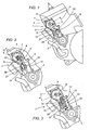
- Figure 1 is a partial side view of an engine fitted with the exhaust valve control device made in accordance with the present invention;
- Figure 2 is a partial side view of an engine fitted with an alternative embodiment of the exhaust valve control device illustrated in Figure 1;
- Figure 3 is a partial side view of an engine fitted with another embodiment of the exhaust valve control device illustrated in Figure 1;
- Figure 4 is a schematic cross-section of a detail of the exhaust valve control device illustrated in the previous figures;
- Figures 5, 6, 7 and 8 are diagrams relating to operation of the exhaust valve control device illustrated in Figure 1;
- Figures 9, 10 and 11 illustrate alternative embodiments of the detail illustrated in Figure 4.
- With reference to Figure 1, the exhaust valve control device disclosed is labelled 1 as a whole, and comprises a
governor 2, of the known type and therefore not illustrated in detail, connected by mechanical connecting means 3 to anexhaust control valve 4, hereinafter referred to simply as thevalve 4, the latter also being of the known type and therefore not illustrated in detail. - As already indicated, this
valve 4 advances or delays opening and closing of the exhaust port of two stroke engines. - In Figure 1 the mechanical connecting means 3 are represented by a
rigid rod 5, hinged to afirst lever 6, in turn directly connected to thevalve 4 actuatingpin 7. - The
governor 2 may be of the type with centrifugal weights, as in the example described in patent US-6 273 036, and has return means, for example a spring, which counters the action of the centrifugal force. However, the present invention is not limited to this type of governor, but may also be applied to any other type of governor: mechanical, pneumatic, electric, etc. - In the embodiment illustrated in Figure 2, the
rigid rod 5 actuates asecond lever 8 which is connected to thefirst level 6 by firstelastic means 9, shown by way of example as atorsion spring 10 which operates in both directions of rotation. - In the embodiment illustrated in Figure 3, the
governor 2 actuates thefirst lever 6 by means of a yieldingrod 11 fitted with secondelastic means 12, shown by way of example as acoil spring 13. - In the case illustrated, the
spring 13 only operates in compression, that is to say, in a single direction of control - opening or closing - of the exhaust control valve. However, obviously, the spring can also act in both directions of control of thevalve 4. - These latter two embodiments have a similar design concept, since in both cases the action of the
governor 2 is not directly on thevalve 4, butelastic means valve 4 opens or closes with a given delay and with an opening curve different to thegovernor 2 command, if the elastic means 9, 12 are active in both directions, or only in opening or closing if the elastic means 9, 12 are only active in one direction. - The exhaust
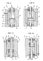
valve control device 1 disclosed may be applied to all of these embodiments, and comprises damper means 14. - Figure 4 schematically illustrates an embodiment of the damper means 14. In this figure the damper means 14 consist of a linear hydraulic shock absorber 15 with the possibility of adjusting the braking.
- Other possible embodiments (not illustrated) of the damper means 14 involve the use of rotary hydraulic shock absorbers attached to the
first lever 6 or to thesecond lever 8, viscostatic shock absorbers or linear or rotary friction shock absorbers, etc. - Overall, although the embodiments of the damper means 14 may vary, the way in which the
control device 1 operates remains the same, as becomes clear from the description of its operation which follows. - The adjustable linear
hydraulic shock absorber 15 comprises acylinder 16, apiston 17, withholes 18, sealably sliding in thecylinder 16, arod 19 attached to thepiston 17. The latter divides theentire cylinder 16 into two zones: anupper zone 16a and alower zone 16b. Therod 19 may be connected to therigid rod 5 or the yieldingrod 11 of thecontrol device 1, or therod 19 may be integral, that is to say, thepiston rod 19 may be therigid rod 5 or part of the yieldingrod 11. In the latter case, as illustrated in Figure 3, therod 11 practically consists of a coaxial spring 13 - shock absorber 15 assembly. - The
cylinder 16 also comprises aduct 20 allowing communication between anupper zone 16a and alower zone 16b of thecylinder 16. In the embodiment illustrated in Figure 4 theduct 20 is made in the wall of thecylinder 16. However, other embodiments are possible, with theduct 20 in a different position. - The inside of the
cylinder 16 is filled with adamper fluid 21, for examplehydraulic oil 22. The upper 16a and lower 16b zones are in fluid communication both through theholes 18 in thepiston 17 and through theduct 20. - As illustrated in Figure 4, the
holes 18 in thepiston 17 are closed by adisk 23, which is held in contact with a face of the piston by a Bellevillespring 24, whilst theduct 20 is partially closed by a screw with a tapered tip which can be more or less tightened so as to vary the passage cross-section. - This configuration allows the achievement of a different adjustment of shock absorber 15 braking in both directions, as described in more detail below.
- In the embodiment illustrated in Figure 9, the
cylinder 16 comprises asecond duct 28 for the freer passage of thehydraulic oil 22 starting from a givenpiston 17 position H. Thesecond duct 28 may have an adjusting screw, similarly to theduct 20. - Therefore, a given degree of shock absorber 15 braking may be obtained as far as
piston 17 position H, and a different degree of braking, in this case less, from the position H. This clearly shows the versatility of thedevice 1, which with just a few modifications can change its operating features. - For this purpose, there may also be other configurations, illustrated in Figures 9 to 11.
- In Figure 9, in addition to the
second duct 28 described above, thecylinder 16 has a modifiedduct 20. In this case, braking is adjusted by means of acalibrated channel 29 in one of thecylinder 16closing caps 30. Theduct 20 passage cross-section is adjusted by substituting thecap 30 with another, which has acalibrated channel 29 with a different cross-section. - Figure 10 illustrates another embodiment of the hydraulic shock absorber 15 in which inside the cylinder there is a substantially
conical needle 31 operating in conjunction with theholes 18, or at least one of theholes 18, or with theonly hole 18 in thepiston 17. Theneedle 31 is inserted in one of thecylinder 16closing caps 30 and may be threaded to change its relative position. The relative position of theneedle 31 may also be changed in steps, locking theneedle 31 using special grooves (not illustrated) in theneedle 31 and an elastic needle fastening peg (not illustrated). - In another embodiment, not illustrated, the
needle 31 is positioned in therod 19 and adjusts the flow of damper fluid passing through a hole (or holes) made in therod 19. - With these embodiments the passage cross-section of the hole 18 (or holes) is variable with the
piston 17 stroke and so the braking applied by theshock absorber 15 is variable. - Figure 11 illustrates another embodiment of the hydraulic shock absorber 15 in which there are another two forms of adjustment of the flow of damper fluid, combined with the previous ones.
- In particular, it should be noticed that in the
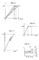
piston 17 there is ascrew 32 for adjusting the passage of ahole 18, allowing it to be altered irrespective of the position of thepiston 17 stroke. Moreover, in thecylinder 16 internal wall there is another channel in the form of a recess 33 which, by increasing the passage cross-section for a given stretch of thepiston 17 stroke, causes a reduction in the degree of hydraulic shock absorber 15 braking for that stretch of thepiston 17 stroke. - Combining all of these forms of adjustment allows the achievement of variations in the damper fluid passage cross-section summarised by way of example in the diagram in Figure 8.
- In this diagram, the "X" axis labelled "stroke" represents the
piston 17 stroke, whilst the "Y" axis labelled "A" represents the damper fluid passage cross-section for thatpiston 17 position. - Obviously the passage cross-section partially determines the flow of damper fluid and, therefore, ultimately, the degree of braking supplied by the
shock absorber 15. - Six different curves are illustrated, numbered 101 to 106, whose features may be summarised as follows:
- 101, gradually increasing flow of damper fluid;
- 102, flow of damper fluid constant up to 3/4 of the
piston 17 stroke, then gradually increasing; - 103, flow of damper fluid constant up to 2/4 of the
piston 17 stroke, then gradually increasing, then constant again; - 104, constant flow of damper fluid;
- 105, flow of damper fluid constant up to 2/4 of the
piston 17 stroke, then gradually falling, then constant again; - 106, flow of damper fluid constant up to 2/4 of the
piston 17 stroke, gradually increasing and falling in succession, then becoming constant again at almost the starting level. -
- The outside of the
device 1 is protected by acover 26, partially illustrated in the figures, which may havefins 27 to promotedevice 1 cooling. Thecover 26 and thecylinder 16 may be made as a single piece to promote cooling and simplify construction. Thedevice 1 disclosed operates as follows. - The
valve 4 has two main positions: one closed, in which the upper edge of the engine exhaust port is lower, suitable for low speeds, and one open, in which the upper edge of the engine exhaust port is higher, suitable for higher speeds. - The
governor 2 determines the position of thevalve 4, open or closed, mainly based on the engine speed (number of revolutions). - Most governors use weights - for example ball bearings - subject to centrifugal force, and so determine a single governor position for each engine speed.
- Generally speaking, the
governor 2 actuates thevalve 4 between the two main positions, closed or open, whilstvalve 4 intermediate positions are relatively less frequent, partly because the range is relatively narrow in terms of both valve adjustment amplitude and the range of engine speeds (number of revolutions) in whichvalve 4 adjustment (variation) takes place. - These adjustments determine the engine's maximum power or driving torque.
- However, generally transient motor vehicle driving conditions occur in which the maximum power or maximum driving torque are not the best quality required of the engine to achieve maximum motor vehicle acceleration.
- This happens particularly in conditions in which there is a low level of grip between the vehicle wheel and the ground, and in any event in conditions in which the driving torque at the wheel exceeds that which can be transmitted.
- For these reasons, the engine's maximum power or driving torque must be limited for a given period of time, in particular during the transition between one speed and the other, for example, when switching from a given number of engine revolutions to a higher number of engine revolutions.
- This is achieved with the
device 1 disclosed, braking the movement of thevalve 4 which does not immediately pass from the closed position to the open position (or vice versa). - The movement supplied by the
governor 2 to thevalve 4 occurs with a gradual and retarded passage due to the braking applied by theshock absorber 15. As already indicated relative to the diagram in Figure 8, the movement can be braked gradually and in a variable manner and may be different during opening and closing. With reference to theshock absorber 15 in Figure 4, it should be noticed that thepiston 17 upward movement is braked in theduct 20 passage by adjusting thescrew 25, since thedisk 23 completely closes theholes 18 in thepiston 17. Thepiston 17 downward movement may be braked relatively little by thedisk 23, if theBelleville spring 24 which holds it in contact with the face of thepiston 17 is quite yielding so that thedisk 23 rises relatively easily, theholes 18 opening easily as a result and allowing an ample flow ofdamper fluid 21. - By suitably connecting the
shock absorber 15 to thevalve 4pin 7, a braked movement can be obtained forvalve 4 opening and a relatively free movement for reaching thevalve 4 closed position. - In particular, in the examples illustrated in Figures 2 and 3, the braking effect is more obvious because the
governor 2 acts through theelastic means valve 4. In the example in Figure 1, the braking action is less prevalent because thegovernor 2 acts directly on thevalve 4 which is connected by therigid rod 5. -
Device 1 operation is now described in detail relative to the conditions illustrated in the diagrams in Figures 5, 6 and 7. - In these diagrams the "X" axis labelled "time" represents the time which elapses during the change in engine speed, whilst the "Y" axis labelled "α", represents the angle of movement of the
valve 4pin 7. - In other words, "α" represents the degree of
valve 4 opening, starting with "α"=0 which corresponds to thevalve 4 in the position with the exhaust port closed, up to "α"="α max" corresponding to thevalve 4 in the position with the exhaust port open. - The diagram in Figure 6 illustrates
valve 4 opening after a constant increase in the number of engine revolutions. The continuous line represents valve opening without theshock absorber 15 and the dashed line represents valve opening with theshock absorber 15. - In the
first case valve 4 opening occurs by passing from "α"=0 and time=0, to a value of "α"="α max" in a time=T1 (without shock absorber 15). In the second case the value "α"="α max" is reached in a time=T2 greater than T1 and with a more gradual trend. - As is clearly illustrated by the diagram in Figure 6, the achievement of
maximum valve 4 opening no longer depends directly on the number of revolutions, but thevalve 4 maximum opening value "α"="α max" is reached after a given period of time - the difference between T2 and T1 - which depends on the more or less marked braking effect of theshock absorber 15. - The diagram in Figure 5 illustrates
valve 4 opening after a constant increase in the number of engine revolutions, and is relative to twodifferent shock absorber 15 braking values. These two different braking values give two different opening curves and two different times T3, T4 for reaching thevalve 4 maximum opening value "α"="αmax". The area between the two opening curves may be covered by varying theshock absorber 15 braking as illustrated in the examples in Figures 8 to 11. For example, Figure 5 illustrates a third opening curve, indicated with a dashed line, in the middle of the hatched area, which requires a time T5 for reaching thevalve 4 maximum opening value "α"="α max". - It should also be noticed that this curve has an intermediate vertical bend caused by a temporary reduction in the
shock absorber 15 braking. This reduction in braking may be obtained by following one of the examples illustrated in Figures 8 to 11. Finally, the diagram in Figure 7 illustrates thevalve 4 opening (or closing) curves, as a function of time, following an alternate variation in the number of engine revolutions, followed by a final increase in the number of revolutions. The continuous line represents the variation in the angle "α" without theshock absorber 15, whilst the dashed line represents the variation in the angle "α" with theshock absorber 15. - As can be seen in the diagram in Figure 7, the dashed line curve relative to the
device 1 disclosed has a more gradual trend without peaks duringvalve 4 opening or closing. This also translates into a softer engine power or torque supply, so that the vehicle driver can concentrate on driving and does not have to deal with problems of grip due to excessive power relative to the traction possibilities offered by the type of ground and the tyre fitted on the vehicle. - As is evident from the above description, the
device 1 disclosed allows the achievement of improved engine operation in a way similar to that which can be achieved with electric - electronic adjusting means. Thedevice 1 disclosed is also very versatile, since - as illustrated in the examples - very different operating modes can be achieved with small variations in the construction. The invention described can be subject to numerous modifications and variations without thereby departing from the scope of the inventive concept defined in the claims. Moreover, all the details of the invention may be substituted by technically equivalent elements. -
- 1
- control device
- 2
- governor
- 3
- mechanical connecting means
- 4
- exhaust valve
- 5
- rigid rod
- 6
- first lever
- 7
-
valve 4 actuating pin - 8
- second lever
- 9
- first elastic means
- 10
- torsion spring
- 11
- yielding rod
- 12
- second elastic means
- 13
- coil spring
- 14
- damper means
- 15
- linear hydraulic shock absorber
- 16
- cylinder
- 16a
- upper zone of the
cylinder 16 - 16b
- lower zone of the
cylinder 16 - 17
- piston
- 18
- holes in piston
- 19
- rod
- 20
- passage duct
- 21
- damper fluid
- 22
- hydraulic oil
- 23
- disk
- 24
- Belleville spring
- 25
- adjusting screw
- 26
- cover
- 27
- cooling fin
- 28
- second passage duct
- 29
- calibrated channel
- 30
-
cylinder 16 closing cap - 31
- needle
- 32
- adjusting screw for
holes 18 - 33
- recess in cylinder wall.
Claims (12)
- An exhaust valve control device (1) for two stroke engines for vehicle traction, the device (1) comprising a governor (2), means (3) for connecting the governor (2) to an exhaust control valve (4), able to advance or retard opening of the engine exhaust port, the control device being characterised in that it comprises damper means (14) attached to the connecting means (3).
- The control device (1) according to claim 1, characterised in that the damper means (14) comprise a hydraulic shock absorber (15) with adjustable braking.
- The control device (1) according to claim 1 or 2, characterised in that the governor (2) connecting means (3) comprise a rigid rod (5).
- The control device (1) according to claim 1 or 2, characterised in that the governor (2) connecting means (3) comprise a yielding rod (11) made using elastic means (9, 12).
- The control device (1) according to any of the foregoing claims, characterised in that the damper means (14) are connected to the valve (4).
- The control device (1) according to any of the foregoing claims from 2 to 5, characterised in that the adjustable hydraulic shock absorber (15) comprises: a cylinder (16); a piston (17) which divides the inside of the cylinder (16) into two zones: one upper (16a) and one lower (16b), the piston (17) having holes (18) in it and sealably sliding in the cylinder (16); there being a rod (19) attached to the piston (17).
- The control device (1) according to claim 6, characterised in that the cylinder (16) comprises a hydraulic passage duct (20) between the upper zone (16a) and the lower zone (16b).
- The control device (1) according to claim 7, characterised in that the duct (20) comprises an adjusting screw (25) for varying the duct (20) passage cross-section.
- The control device (1) according to claim 7, characterised in that the duct (20) comprises a calibrated channel (29) for varying the duct (20) passage cross-section.
- The control device (1) according to any of the foregoing claims from 6 to 9, characterised in that the piston (17) comprises a disk (23) for closing the holes (18) and a Belleville spring (24) which keeps the disk (23) in contact with a face of the piston (17).
- The control device (1) according to any of the foregoing claims from 6 to 10, characterised in that the cylinder (16) comprises a tapered needle (31) fixed to the cylinder (16) and operating in conjunction with at least one of the holes (18) in the piston (17), so as to vary the passage cross-section of at least one of the holes (18) according to the piston (17) stroke.
- The control device (1) according to any of the foregoing claims from 6 to 11, characterised in that the cylinder (16) comprises a second passage duct (28) or a recess (33), forming another damper fluid (21) passage between two parts of the cylinder (16).
Applications Claiming Priority (2)
| Application Number | Priority Date | Filing Date | Title |
|---|---|---|---|
| ITBO20020248 | 2002-04-30 | ||
| IT2002BO000248A ITBO20020248A1 (en) | 2002-04-30 | 2002-04-30 | CONTROL DEVICE FOR THE EXHAUST VALVE IN TWO STROKE ENGINES |
Publications (1)
| Publication Number | Publication Date |
|---|---|
| EP1361353A2 true EP1361353A2 (en) | 2003-11-12 |
Family
ID=11440094
Family Applications (1)
| Application Number | Title | Priority Date | Filing Date |
|---|---|---|---|
| EP03009604A Withdrawn EP1361353A2 (en) | 2002-04-30 | 2003-04-29 | An exhaust valve control device for two stroke engine |
Country Status (2)
| Country | Link |
|---|---|
| EP (1) | EP1361353A2 (en) |
| IT (1) | ITBO20020248A1 (en) |
Cited By (1)
| Publication number | Priority date | Publication date | Assignee | Title |
|---|---|---|---|---|
| ES2394805R1 (en) * | 2011-02-09 | 2013-08-05 | Gas Gas Motos S A | DEVICE FOR EXHAUST MOTOR VALVE REGULATION |
-
2002
- 2002-04-30 IT IT2002BO000248A patent/ITBO20020248A1/en unknown
-
2003
- 2003-04-29 EP EP03009604A patent/EP1361353A2/en not_active Withdrawn
Cited By (1)
| Publication number | Priority date | Publication date | Assignee | Title |
|---|---|---|---|---|
| ES2394805R1 (en) * | 2011-02-09 | 2013-08-05 | Gas Gas Motos S A | DEVICE FOR EXHAUST MOTOR VALVE REGULATION |
Also Published As
| Publication number | Publication date |
|---|---|
| ITBO20020248A1 (en) | 2003-10-30 |
| ITBO20020248A0 (en) | 2002-04-30 |
Similar Documents
| Publication | Publication Date | Title |
|---|---|---|
| US5752891A (en) | Electronically controlled accessory drive system for the automotive engine | |
| US6192841B1 (en) | Device to limit valve seating velocities in limited lost motion tappets | |
| US8950559B2 (en) | Adjustable shock absorber | |
| EP0543210B1 (en) | Engine comprising a continuous braking device, particularly for an industrial vehicle | |
| US4408580A (en) | Hydraulic valve lift device | |
| US4387673A (en) | Valve opening control device | |
| EP1361353A2 (en) | An exhaust valve control device for two stroke engine | |
| JPH0243057B2 (en) | ||
| JP5146354B2 (en) | Control device for internal combustion engine | |
| JPH07259516A (en) | Valve opening / closing timing control device | |
| US7334550B2 (en) | Valve train and cam lobe | |
| WO2005035349A1 (en) | Steering damper for a motorcycle | |
| CA1249753A (en) | Engine camshaft drive mechanism | |
| JPH023060B2 (en) | ||
| US4987875A (en) | Fuel injection pump for supplying the combustion chambers of internal combustion engines intended for vehicle operation | |
| JPS5923786A (en) | Shock absorber for motorcycle | |
| EP4065822A1 (en) | A valve control system and methods of operation thereof | |
| KR100378304B1 (en) | Vehicle speed power steering | |
| KR200178173Y1 (en) | Car shock absorber | |
| CN112709791B (en) | Tensioner oil pressure regulating system and oil pressure regulating method for automobile engine | |
| EP0719909B1 (en) | A valve control system for an internal combustion engine | |
| KR20030049220A (en) | variation system of valve spring stiffness for automotive vehicles | |
| KR100235187B1 (en) | Variable Shock Absorber of Vehicle Suspension | |
| KR19990074022A (en) | Shock absorber with variable damping force | |
| KR101716977B1 (en) | Method for preventing damage to engine of vehicle |
Legal Events
| Date | Code | Title | Description |
|---|---|---|---|
| PUAI | Public reference made under article 153(3) epc to a published international application that has entered the european phase |
Free format text: ORIGINAL CODE: 0009012 |
|
| AK | Designated contracting states |
Kind code of ref document: A2 Designated state(s): AT BE BG CH CY CZ DE DK EE ES FI FR GB GR HU IE IT LI LU MC NL PT RO SE SI SK TR |
|
| AX | Request for extension of the european patent |
Extension state: AL LT LV MK |
|
| STAA | Information on the status of an ep patent application or granted ep patent |
Free format text: STATUS: THE APPLICATION IS DEEMED TO BE WITHDRAWN |
|
| 18D | Application deemed to be withdrawn |
Effective date: 20051102 |