EP1361154A1 - Dispositif de protection pour coupe-filin - Google Patents
Dispositif de protection pour coupe-filin Download PDFInfo
- Publication number
- EP1361154A1 EP1361154A1 EP03291083A EP03291083A EP1361154A1 EP 1361154 A1 EP1361154 A1 EP 1361154A1 EP 03291083 A EP03291083 A EP 03291083A EP 03291083 A EP03291083 A EP 03291083A EP 1361154 A1 EP1361154 A1 EP 1361154A1
- Authority
- EP
- European Patent Office
- Prior art keywords
- protective device
- shells
- annular
- semi
- shell
- Prior art date
- Legal status (The legal status is an assumption and is not a legal conclusion. Google has not performed a legal analysis and makes no representation as to the accuracy of the status listed.)
- Granted
Links
- 230000001681 protective effect Effects 0.000 claims description 23
- 239000000463 material Substances 0.000 claims description 4
- 229920001684 low density polyethylene Polymers 0.000 claims description 3
- 239000004702 low-density polyethylene Substances 0.000 claims description 3
- 229920002994 synthetic fiber Polymers 0.000 claims 1
- 230000002093 peripheral effect Effects 0.000 description 5
- 238000000465 moulding Methods 0.000 description 4
- XLYOFNOQVPJJNP-UHFFFAOYSA-N water Substances O XLYOFNOQVPJJNP-UHFFFAOYSA-N 0.000 description 3
- 230000004323 axial length Effects 0.000 description 2
- 230000006866 deterioration Effects 0.000 description 2
- 238000002347 injection Methods 0.000 description 2
- 239000007924 injection Substances 0.000 description 2
- 238000009434 installation Methods 0.000 description 2
- 238000003754 machining Methods 0.000 description 2
- 238000012423 maintenance Methods 0.000 description 2
- 229920003023 plastic Polymers 0.000 description 2
- 239000004033 plastic Substances 0.000 description 2
- 230000009286 beneficial effect Effects 0.000 description 1
- 239000000470 constituent Substances 0.000 description 1
- 239000013013 elastic material Substances 0.000 description 1
- 235000008216 herbs Nutrition 0.000 description 1
- 238000003780 insertion Methods 0.000 description 1
- 230000037431 insertion Effects 0.000 description 1
- 238000004519 manufacturing process Methods 0.000 description 1
- 239000002184 metal Substances 0.000 description 1
- 239000011347 resin Substances 0.000 description 1
- 229920005989 resin Polymers 0.000 description 1
- 239000000243 solution Substances 0.000 description 1
Images

Classifications
-
- B—PERFORMING OPERATIONS; TRANSPORTING
- B63—SHIPS OR OTHER WATERBORNE VESSELS; RELATED EQUIPMENT
- B63H—MARINE PROPULSION OR STEERING
- B63H5/00—Arrangements on vessels of propulsion elements directly acting on water
- B63H5/07—Arrangements on vessels of propulsion elements directly acting on water of propellers
- B63H5/16—Arrangements on vessels of propulsion elements directly acting on water of propellers characterised by being mounted in recesses; with stationary water-guiding elements; Means to prevent fouling of the propeller, e.g. guards, cages or screens
- B63H5/165—Propeller guards, line cutters or other means for protecting propellers or rudders
Definitions
- the present invention relates to a device for protection for rope cutter.
- Line cutters are installed on the trees of the propulsion propellers for boats and ships, with function of cutting any cable or rope that comes wind around these trees and propellers.
- Document FR2768120 discloses a wire cutter intended to be mounted on a boat propeller shaft, in particular to on-board motor, between the outer end of the tube stern of it and the propeller, to cut the lines or others, which could otherwise wrap around the propeller shaft and, in cooperation with the stern tube, block it.
- rope we mean many elements that can be in the water at the propeller shaft, such that: ropes, fishing lines, parts of fishing nets, herbs or other, generally having a form elongate.
- Rope cutters of this type include for example a fixing hub on a motor boat propeller shaft on-board, an annular disc extending radially to from the outside of the hub and presenting on its outer periphery a circular cutting edge and on its face intended to be opposite the stern tube a cutting element projecting axially with an edge of section located in a radial plane spaced from the face stern.
- the object of the present invention is to remedy this situation by proposing a protective device for rope cutter which provides both protection of rope cutter users and installers as well as people likely to approach a rope cutter by example when a boat is out of water, and a protection of wire cutters against the risks of accidental deterioration.
- This objective is achieved with a protection for a cable cutter intended to be mounted on a onboard motor boat propeller shaft with a attachment hub to a propeller shaft and at least one sharp part, characterized in that it comprises two annular half-shells intended to enclose in position assembling said cutting part inside said annular half-shells.
- the protection device according to the invention can be used repositionably, due to its structure in two half-shells, either for transport and handling of a rope cutter not installed or disassembled, i.e. to completely cover an installed and fixed cable cutter on a propeller shaft.
- each annular half-shell can advantageously have an internal groove arranged to receive this cutting circular edge.
- each half-shell can then include in addition to a first semi-cylindrical housing provided for receive this axial circular cutting element.
- each first semi-cylindrical housing has a substantially axial depth greater than the thickness of the circular cutting element axial, so as to ensure total protection of this cutting element in the event of impact or fall.
- the two annular half-shells can also be advantageously provided for enclosing in the assembled position at least part of the fixing hub.
- Each half-shell then further comprises a second semi-cylindrical housing designed to receive at least part of the hub fixation.
- each second semi-cylindrical housing can be partially closed by an annular part of closure extending from the outer periphery of each half-shell, and has a depth determined so to receive the outer main body of the hub.
- the annular closure parts are furthermore arranged to define a diameter opening sufficient to allow the passage of a propeller shaft.
- the diameter of the groove can advantageously be chosen equal to or greater than that of the circular cutting edge of the cable cutter and the diameters of the second housings cylindrical are preferably determined, coaxially with diameter of the groove, so that the two half-shells annulars surround the hub of a cable cutter, so that serve as a radial stop for the two annular half-shells in position on the cable cutter. So the half-shells do not exert stress or wear on the edge circular cutting.
- the two half-shells can be made of many ways, for example by molding or by machining, with various materials, for example metal, made of plastic or resin.
- the constituent material can advantageously have sufficient elasticity to facilitate the insertion of the rope cutter in both half-shells, and ensuring the maintenance of the half-shells by pinch on the cable cutter.
- a half-shell can be pinched on the cable cutter between the part closing ring of the second cylindrical housing, in support on the hub, and an opposite face of the groove, in support on the annular disc.
- At least one of the two half-shells can be produced in one piece, for example by injection, molding or machining of a block.
- This protection device 1 is designed for the protection of a cable cutter 2 comprising a hub cylindrical 23 including a first end face 25 defines a part of a stern face which, in the state mounted, faces the outer end face 30 of a stern tube 3 and close to it, and a annular disc 20 extending radially from the outer surface of the hub 23 in an area adjacent to this first end face 25 of the hub 23.
- One of the faces of the annular disc 20 constitutes the other part of the stern face and its outer periphery has an edge cutting circular 21.
- the wire cutter 2 further comprises a cutting element 22 projecting axially from the stern face, with a cutting edge located in a plane radial spaced from the stern face.
- the device protection 1 consists of two half-shells 1.1, 1.2 provided to enclose the rope cutter 2, whether the latter is actually installed on a propeller shaft or whatever not installed and handled as an isolated component.
- Each half-shell 1.1, 1.2 is of semi-cylindrical external shape. They are each delimited externally by a semi-cylindrical outer surface 40.1, 40.2.
- Each half-shell has an interior groove cylindrical 10.1, 10.2 designed to receive the edge circular cutting 21 of the wire cutter 2, located on the one hand between a first semi-cylindrical housing 11.1, 11.2 provided to receive the axial cutting element 22 and on the other hand a second semi-cylindrical housing 12.1, 12.2 provided for receive the outer main body 26 from the hub 23 of the rope cutter 2.
- the first semi-cylindrical housing 11.1, 11.2 is defined by a first semi-annular closure part 15.1, 15.2 integral part of each half-hull 1.1, 1.2 and extending from the inner part of the half-shell towards the interior of the device. Axially, the depth of the first semi-cylindrical housing is chosen more greater than the axial length of the axial cutting element 22, while their diameter is chosen to be greater than that of said axial cutting element 22.
- the second semi-cylindrical housing 12.1, 12.2 is partially closed by a second semi-annular part closure 14.1, 14.2 integral part of each half-shell 1.1, 1.2 and extending radially from the part interior of the half-shell towards the interior of the device.
- This partial closure defines a cylindrical zone 13.1, 13.2 provided to leave sufficient play around the propeller shaft when the protection device 1 is installed on a wire cutter in place on this tree.
- the axial distance between a first semi-annular part 14.1, 14.2 and the second part of closure 15.1, 15.2 on the same half-shell is chosen substantially equal to or less than the axial length of the way.
- the half-shell can be maintained by pinching, i.e. increased force, between the face of the stern of the annular disc 20 on which the first annular part 14.1, 14.2 and a rear face 24 of the hub, axially opposite the stern face 25, on which is supported by the second annular part 15.1, 15.2.
- the diameter of the inner cylindrical groove 10.1, 10.2 is greater than the outside diameter of the circular edge cutting 21 of the rope cutter and the diameters of the second cylindrical housings 12.1, 12.2 are preferably determined, coaxial with the groove, so that the two annular half-shells enclose the hub 23 of the rope cutter, so as to serve as a radial stop for the two half-shells annular in position on the cable cutter. So, the half-shells do not exert radial stress or wear on the circular cutting edge 21.
- each half-shell is moved radially relative to the cable cutter 2 so that the annular disc 20 penetrates in the two grooves 10.1, 10.2 of the two half-shells 1.1, 1.2 until the teeth of the circular cutting edge 21 come into contact with the peripheral walls inside the grooves of the two half-shells 1.1, 1.2.
- the half-shells are then held firmly on the cable cutter and separated by a small gap thickness, for example 2 mm.
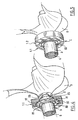
- protection device 1 in two half-shells 1.1, 1.2 allows mounting direct on a rope cutter 1 installed on a shaft 6 of a propeller 5, as illustrated in figures 4 and 5.
- the half shells can include connecting means 41 for holding together the two half-shells in their position on the rope cutter. This is particularly beneficial in ensuring that the half-shells remain in place, even if wear on the rope cutter does not allow the forced mounting of the half-shells.
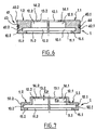
- the connecting means include in each of the semi-cylindrical exterior surfaces 40.1, 40.2, a semi-annular groove respective 42.1, 42.2. These two gorges form together, when the protective device is in place, a groove device 43.
- a link 44 is housed in the peripheral groove 43, thus ensuring the connection between the half-shells.
- the link can advantageously be an elastic ring.
- the device 5 does not include a semi-cylindrical outer surface, the exterior surfaces 50.1, 50.2, follow substantially the internal geometry of the device, such as previously described, so that the protection is of substantially uniform thickness Ep, and thin.
- the second embodiment can be made by plastic injection of an elastic material deformable, for example from Low Density Polyethylene (LDPE).
- LDPE Low Density Polyethylene
- a device according to the second embodiment for the same external diameter 80 mm line cutter, the outside diameter of the protective device can be 85 mm and its thickness may be substantially uniform from 2 to 3 mm.
- the invention is not limited to the examples which have just been described and numerous arrangements can be brought to these examples without departing from the framework of the invention.
- the structure and internal geometry of the protective device can be adapted to the specific geometry of each rope cutter.
- the external shape of the protective device can not be cylindrical.
- the two half-shells connected by articulation can be molded in one piece comprising the two connected half-shells by the joint.
- the joint can thus be molded simultaneously with half-shells in the same material adapted.
- the joint can also be an included insert during the molding of the half-shells.
- the connecting hubs can also be from another type that a link in a peripheral groove and for example include straps.
- the throat may not be peripheral and only extend over part of one or of the two half-shells.
Landscapes
- Chemical & Material Sciences (AREA)
- Engineering & Computer Science (AREA)
- Combustion & Propulsion (AREA)
- Mechanical Engineering (AREA)
- Ocean & Marine Engineering (AREA)
- Processing Of Stones Or Stones Resemblance Materials (AREA)
- Ultra Sonic Daignosis Equipment (AREA)
- Excavating Of Shafts Or Tunnels (AREA)
- Turning (AREA)
- Dicing (AREA)
- Grinding-Machine Dressing And Accessory Apparatuses (AREA)
- Harvester Elements (AREA)
- Polishing Bodies And Polishing Tools (AREA)
Abstract
Description
- la figure 1 est une vue d'un premier mode de réalisation pour un dispositif de protection selon l'invention, dont seule une des demi-coques enserrant une partie d'un coupe-filin est représentée ;
- la figure 2 est une vue de face d'un dispositif de protection selon l'invention ;
- la figure 3 est une vue en coupe d'un dispositif de protection selon l'invention ;
- la figure 4 illustre l'une des deux demi-coques d'un dispositif de protection selon l'invention utilisé en place sur un coupe-filin installé sur un arbre d'hélice ;
- la figure 5 illustre le dispositif de protection de la figure 4 complètement installé sur le coupe-filin ;
- la figure 6 est une figure similaire à la figure 3, le dispositif de protection comprenant en outre des moyens de liaison entre les deux demi-coques ; et,
- la figure 7 est une vue en coupe, similaire aux figures 3 et 6, d'un deuxième mode de réalisation pour un dispositif de protection selon l'invention.
- diamètre extérieur des demi-coques annulaires assemblées : 96 mm
- diamètre intérieur des rainures : 82 mm
- largeur des rainures : 5,1 mm
- diamètre intérieur des deux premiers logements semi-cylindriques assemblés : 68 mm
- profondeur des premiers logements semi-cylindriques : 3,6 mm
- profondeur des seconds logements semi-cylindriques : 9,3 mm
- diamètre intérieur des deux seconds logements semi-cylindriques assemblés : 52,5 mm
- diamètre de passage de l'arbre d'hélice : 32 mm
- épaisseur de la partie de fermeture partielle : 2 mm
Claims (19)
- Dispositif (1) de protection pour un coupe-filin (2) destiné à être monté sur un arbre (6) d'hélice de bateau à moteur embarqué et comportant un moyeu (23) de fixation à l'arbre d'hélice et au moins une partie tranchante (21, 22), caractérisé en ce qu'il comprend deux demi-coques annulaires (1.1, 1.2) prévues pour enserrer en position assemblée ladite partie tranchante (21, 22) à l'intérieur desdites demi-coques annulaires (1.1, 1.2).
- Dispositif de protection selon la revendication 1, pour un coupe-filin (2) comprenant un disque annulaire (20) comportant un bord circulaire coupant (21) s'étendant radialement, caractérisé en ce que chaque demi-coque annulaire (1.1, 1.2) comporte une rainure interne (10.1, 10.2) agencée pour recevoir ledit bord circulaire coupant (21).
- Dispositif de protection selon la revendication 2, pour un coupe-filin (2) comprenant en outre un élément coupant circulaire (22) s'étendant axialement à partir d'une face (25) du disque annulaire (20) prévue pour être en vis à vis d'un tube d'étambot (3), caractérisé en ce que chaque demi-coque (1.1, 1.2) comporte en outre un premier logement semi-cylindrique (11.1, 11.2) prévu pour recevoir ledit élément coupant circulaire axial (22).
- Dispositif de protection selon la revendication 3, caractérisé en ce que chaque premier logement semi-cylindrique (11.1, 11.2) présente une profondeur sensiblement plus grande que l'épaisseur de l'élément coupant circulaire axial (22).
- Dispositif de protection selon l'une des revendications 3 ou 4, caractérisé en ce que les deux demi-coques annulaires (1.1, 1.2) sont aussi prévues pour enserrer en position assemblée au moins une partie du moyeu de fixation (23).
- Dispositif de protection selon la revendication 6, caractérisé en ce que chaque demi-coque (1.1, 1.2) comporte en outre un second logement semi-cylindrique (12.1, 12.2) prévu pour recevoir au moins une partie du moyeu de fixation (23).
- Dispositif de protection selon la revendication 6, caractérisé en ce que chaque second logement semi-cylindrique (12.1, 12.2) est partiellement fermé par une partie annulaire de fermeture (14.1, 14.2) s'étendant de la périphérie extérieure de chaque demi-coque (1.1, 1.2).
- Dispositif de protection selon la revendication 7, caractérisé en ce que chaque second logement semi-cylindrique (12.1, 12.2) présente une profondeur déterminée de façon à recevoir le corps principal extérieur (26) du moyeu (23).
- Dispositif de protection selon l'une des revendications 7 ou 8, caractérisé en ce que les parties annulaires de fermeture (14.1, 14.2) sont agencées de façon à définir une ouverture (13.1, 13.2) de diamètre suffisant pour permettre le passage d'un arbre d'hélice.
- Dispositif de protection selon l'une des revendications 2 à 9, caractérisé en ce que la rainure (10.1, 10.2) de chaque demi-coque (1.1, 1.2) présente une largeur sensiblement également ou inférieure à l'épaisseur du disque annulaire (20).
- Dispositif de protection selon l'une quelconque des revendications précédentes, caractérisé en ce que l'une au moins des deux demi-coques est réalisée en une seule pièce.
- Dispositif de protection selon l'une quelconque des revendications précédentes, caractérisé en ce que l'une au moins des demi-coques est réalisée dans un matériau synthétique.
- Dispositif de protection selon la revendication 12, caractérisé en ce que le matériau est du Polyéthylène Basse Densité.
- Dispositif de protection selon l'une des revendications 7 à 13, caractérisé en ce que chaque premier logement semi-cylindrique (11.1, 11.2) est défini par une première partie annulaire de fermeture (15.1, 15.2) s'étendant de la périphérie extérieure de chaque demi-coque (1.1, 1.2) et que les demi-coques sont maintenues par pincement axial des premières et secondes parties annulaires de fermeture sur le coupe-filin.
- Dispositif de protection selon l'une des revendications 7 à 13, caractérisé en ce que le second logement (12.1, 12.2)est prévu pour venir radialement en butée sur le moyeu.
- Dispositif de protection selon l'une quelconque des revendications précédentes, caractérisé en ce qu'il comprend une articulation reliant les deux demi-coques.
- Dispositif de protection selon l'une quelconque des revendications précédentes, caractérisé en ce qu'il est d'épaisseur (Ep) sensiblement homogène.
- Dispositif de protection selon l'une quelconque des revendications précédentes, caractérisé en ce qu'il comprend des moyens de liaison (41) pour maintenir ensemble les deux demi-coques dans leur position sur le coupe-filin.
- Dispositif de protection selon la revendication 18, caractérisé en ce que les moyens de liaison (41) comprennent dans une surface extérieure (40.1, 40.2) de l'une au moins des demi-coques une gorge (42.1, 42.2) et un lien (44) prévu pour être logé dans la gorge.
Applications Claiming Priority (2)
| Application Number | Priority Date | Filing Date | Title |
|---|---|---|---|
| FR0205675A FR2839492B1 (fr) | 2002-05-07 | 2002-05-07 | Dispositif de protection pour coupe-filin |
| FR0205675 | 2002-05-07 |
Publications (2)
| Publication Number | Publication Date |
|---|---|
| EP1361154A1 true EP1361154A1 (fr) | 2003-11-12 |
| EP1361154B1 EP1361154B1 (fr) | 2005-07-27 |
Family
ID=29226236
Family Applications (1)
| Application Number | Title | Priority Date | Filing Date |
|---|---|---|---|
| EP03291083A Expired - Lifetime EP1361154B1 (fr) | 2002-05-07 | 2003-05-06 | Dispositif de protection pour coupe-filin |
Country Status (5)
| Country | Link |
|---|---|
| EP (1) | EP1361154B1 (fr) |
| AT (1) | ATE300466T1 (fr) |
| DE (1) | DE60301082T2 (fr) |
| ES (1) | ES2247499T3 (fr) |
| FR (1) | FR2839492B1 (fr) |
Cited By (1)
| Publication number | Priority date | Publication date | Assignee | Title |
|---|---|---|---|---|
| CN104044718A (zh) * | 2013-03-12 | 2014-09-17 | 张建新 | 锯齿推进器 |
Citations (3)
| Publication number | Priority date | Publication date | Assignee | Title |
|---|---|---|---|---|
| US5246345A (en) * | 1992-10-07 | 1993-09-21 | Adams Jr Michael J | Boat propeller cover |
| FR2768120A1 (fr) | 1997-09-11 | 1999-03-12 | Jean Claude Geron | Coupe-filin |
| US6085557A (en) * | 1998-08-07 | 2000-07-11 | Kaye, Jr.; Kenneth B. | Anti-theft device for marine propellers |
-
2002
- 2002-05-07 FR FR0205675A patent/FR2839492B1/fr not_active Expired - Lifetime
-
2003
- 2003-05-06 DE DE60301082T patent/DE60301082T2/de not_active Expired - Lifetime
- 2003-05-06 EP EP03291083A patent/EP1361154B1/fr not_active Expired - Lifetime
- 2003-05-06 ES ES03291083T patent/ES2247499T3/es not_active Expired - Lifetime
- 2003-05-06 AT AT03291083T patent/ATE300466T1/de not_active IP Right Cessation
Patent Citations (3)
| Publication number | Priority date | Publication date | Assignee | Title |
|---|---|---|---|---|
| US5246345A (en) * | 1992-10-07 | 1993-09-21 | Adams Jr Michael J | Boat propeller cover |
| FR2768120A1 (fr) | 1997-09-11 | 1999-03-12 | Jean Claude Geron | Coupe-filin |
| US6085557A (en) * | 1998-08-07 | 2000-07-11 | Kaye, Jr.; Kenneth B. | Anti-theft device for marine propellers |
Cited By (1)
| Publication number | Priority date | Publication date | Assignee | Title |
|---|---|---|---|---|
| CN104044718A (zh) * | 2013-03-12 | 2014-09-17 | 张建新 | 锯齿推进器 |
Also Published As
| Publication number | Publication date |
|---|---|
| ES2247499T3 (es) | 2006-03-01 |
| FR2839492A1 (fr) | 2003-11-14 |
| FR2839492B1 (fr) | 2004-07-16 |
| ATE300466T1 (de) | 2005-08-15 |
| DE60301082T2 (de) | 2006-06-08 |
| DE60301082D1 (de) | 2005-09-01 |
| EP1361154B1 (fr) | 2005-07-27 |
Similar Documents
| Publication | Publication Date | Title |
|---|---|---|
| CA1307673C (fr) | Capot d'entree non tournant de turboreacteur a fixation centrale et turboreacteur ainsi equipe | |
| EP1186227B1 (fr) | Sécateur | |
| EP2978668B1 (fr) | Dispositif d'articulation à rotule pour la suspension d'une turbomachine a un pylone ou la suspension d'un equipement au corps de la turbomachine | |
| FR3028717A1 (fr) | Outil electroportatif a transmission protegee. | |
| FR2473151A1 (fr) | Dispositif de raccordement de tuyaux | |
| WO2012049386A1 (fr) | Dispositif de liaison d'un cadre avant d'inverseur de poussée à un carter de soufflante, et nacelle incorporant un tel dispositif | |
| EP1489713B1 (fr) | Dispositif de traversée étanche de paroi | |
| CA2777285A1 (fr) | Element de connexion electrique de turbomachine | |
| FR2712744A1 (fr) | Dispositif de traversée étanche à membrane souple et opercule jetable. | |
| EP1361154B1 (fr) | Dispositif de protection pour coupe-filin | |
| EP2927491A1 (fr) | Pompe de circulation de fluide munie d'un moteur comportant deux parties montees libres en rotation | |
| EP0737114A1 (fr) | Procede de retreint | |
| EP0378471B1 (fr) | Connecteur pour câbles à fibres optiques | |
| FR2832948A1 (fr) | Outil de coupe ou analogue tel que secateur comprenant deux organes actifs pivotant | |
| EP2366275B1 (fr) | Dispositif de fixation de couteaux sur le rotor d'une faucheuse-débroussailleuse | |
| EP0902997B1 (fr) | Dispositif pour le montage d'au moins un cable dans un disque destine a etre positionne dans un manchon de protection d'un raccordement de cables | |
| FR2877994A1 (fr) | Support de palier, et moteur d'aeronef equipe d'un tel support de palier. | |
| EP0208582A1 (fr) | Mandrin d'enroulement notamment pour sangle de sécurité | |
| FR2926613A1 (fr) | Disque de soufflante de turbomachine | |
| EP0625453A1 (fr) | Articulation de palonnier pour dispositif d'essuie-glace | |
| EP3814615B1 (fr) | Assemblage d'un flexible d'échappement et d'un dispositif de protection | |
| EP4098299B1 (fr) | Dispositif de protection d'aiguille pour seringue | |
| EP2237385B1 (fr) | Garniture de passe cable | |
| FR2768120A1 (fr) | Coupe-filin | |
| EP1918601B1 (fr) | Butée d'embrayage |
Legal Events
| Date | Code | Title | Description |
|---|---|---|---|
| PUAI | Public reference made under article 153(3) epc to a published international application that has entered the european phase |
Free format text: ORIGINAL CODE: 0009012 |
|
| AK | Designated contracting states |
Kind code of ref document: A1 Designated state(s): AT BE BG CH CY CZ DE DK EE ES FI FR GB GR HU IE IT LI LU MC NL PT RO SE SI SK TR |
|
| AX | Request for extension of the european patent |
Extension state: AL LT LV MK |
|
| 17P | Request for examination filed |
Effective date: 20040505 |
|
| AKX | Designation fees paid |
Designated state(s): AT BE BG CH CY CZ DE DK EE ES FI FR GB GR HU IE IT LI LU MC NL PT RO SE SI SK TR |
|
| GRAP | Despatch of communication of intention to grant a patent |
Free format text: ORIGINAL CODE: EPIDOSNIGR1 |
|
| GRAS | Grant fee paid |
Free format text: ORIGINAL CODE: EPIDOSNIGR3 |
|
| GRAA | (expected) grant |
Free format text: ORIGINAL CODE: 0009210 |
|
| AK | Designated contracting states |
Kind code of ref document: B1 Designated state(s): AT BE BG CH CY CZ DE DK EE ES FI FR GB GR HU IE IT LI LU MC NL PT RO SE SI SK TR |
|
| PG25 | Lapsed in a contracting state [announced via postgrant information from national office to epo] |
Ref country code: CZ Free format text: LAPSE BECAUSE OF FAILURE TO SUBMIT A TRANSLATION OF THE DESCRIPTION OR TO PAY THE FEE WITHIN THE PRESCRIBED TIME-LIMIT Effective date: 20050727 Ref country code: FI Free format text: LAPSE BECAUSE OF FAILURE TO SUBMIT A TRANSLATION OF THE DESCRIPTION OR TO PAY THE FEE WITHIN THE PRESCRIBED TIME-LIMIT Effective date: 20050727 Ref country code: SK Free format text: LAPSE BECAUSE OF FAILURE TO SUBMIT A TRANSLATION OF THE DESCRIPTION OR TO PAY THE FEE WITHIN THE PRESCRIBED TIME-LIMIT Effective date: 20050727 Ref country code: RO Free format text: LAPSE BECAUSE OF FAILURE TO SUBMIT A TRANSLATION OF THE DESCRIPTION OR TO PAY THE FEE WITHIN THE PRESCRIBED TIME-LIMIT Effective date: 20050727 Ref country code: SI Free format text: LAPSE BECAUSE OF FAILURE TO SUBMIT A TRANSLATION OF THE DESCRIPTION OR TO PAY THE FEE WITHIN THE PRESCRIBED TIME-LIMIT Effective date: 20050727 Ref country code: NL Free format text: LAPSE BECAUSE OF FAILURE TO SUBMIT A TRANSLATION OF THE DESCRIPTION OR TO PAY THE FEE WITHIN THE PRESCRIBED TIME-LIMIT Effective date: 20050727 Ref country code: IE Free format text: LAPSE BECAUSE OF FAILURE TO SUBMIT A TRANSLATION OF THE DESCRIPTION OR TO PAY THE FEE WITHIN THE PRESCRIBED TIME-LIMIT Effective date: 20050727 Ref country code: EE Free format text: LAPSE BECAUSE OF FAILURE TO SUBMIT A TRANSLATION OF THE DESCRIPTION OR TO PAY THE FEE WITHIN THE PRESCRIBED TIME-LIMIT Effective date: 20050727 Ref country code: AT Free format text: LAPSE BECAUSE OF FAILURE TO SUBMIT A TRANSLATION OF THE DESCRIPTION OR TO PAY THE FEE WITHIN THE PRESCRIBED TIME-LIMIT Effective date: 20050727 Ref country code: TR Free format text: LAPSE BECAUSE OF FAILURE TO SUBMIT A TRANSLATION OF THE DESCRIPTION OR TO PAY THE FEE WITHIN THE PRESCRIBED TIME-LIMIT Effective date: 20050727 |
|
| REG | Reference to a national code |
Ref country code: GB Ref legal event code: FG4D Free format text: NOT ENGLISH |
|
| REG | Reference to a national code |
Ref country code: CH Ref legal event code: EP |
|
| REG | Reference to a national code |
Ref country code: IE Ref legal event code: FG4D Free format text: LANGUAGE OF EP DOCUMENT: FRENCH |
|
| REF | Corresponds to: |
Ref document number: 60301082 Country of ref document: DE Date of ref document: 20050901 Kind code of ref document: P |
|
| PG25 | Lapsed in a contracting state [announced via postgrant information from national office to epo] |
Ref country code: BG Free format text: LAPSE BECAUSE OF FAILURE TO SUBMIT A TRANSLATION OF THE DESCRIPTION OR TO PAY THE FEE WITHIN THE PRESCRIBED TIME-LIMIT Effective date: 20051027 Ref country code: GR Free format text: LAPSE BECAUSE OF FAILURE TO SUBMIT A TRANSLATION OF THE DESCRIPTION OR TO PAY THE FEE WITHIN THE PRESCRIBED TIME-LIMIT Effective date: 20051027 Ref country code: SE Free format text: LAPSE BECAUSE OF FAILURE TO SUBMIT A TRANSLATION OF THE DESCRIPTION OR TO PAY THE FEE WITHIN THE PRESCRIBED TIME-LIMIT Effective date: 20051027 Ref country code: DK Free format text: LAPSE BECAUSE OF FAILURE TO SUBMIT A TRANSLATION OF THE DESCRIPTION OR TO PAY THE FEE WITHIN THE PRESCRIBED TIME-LIMIT Effective date: 20051027 |
|
| RAP2 | Party data changed (patent owner data changed or rights of a patent transferred) |
Owner name: SOCIETE DELOT & CIE |
|
| PG25 | Lapsed in a contracting state [announced via postgrant information from national office to epo] |
Ref country code: PT Free format text: LAPSE BECAUSE OF FAILURE TO SUBMIT A TRANSLATION OF THE DESCRIPTION OR TO PAY THE FEE WITHIN THE PRESCRIBED TIME-LIMIT Effective date: 20051227 |
|
| PG25 | Lapsed in a contracting state [announced via postgrant information from national office to epo] |
Ref country code: HU Free format text: LAPSE BECAUSE OF FAILURE TO SUBMIT A TRANSLATION OF THE DESCRIPTION OR TO PAY THE FEE WITHIN THE PRESCRIBED TIME-LIMIT Effective date: 20060128 |
|
| GBT | Gb: translation of ep patent filed (gb section 77(6)(a)/1977) |
Effective date: 20060111 |
|
| NLV1 | Nl: lapsed or annulled due to failure to fulfill the requirements of art. 29p and 29m of the patents act | ||
| REG | Reference to a national code |
Ref country code: IE Ref legal event code: FD4D |
|
| REG | Reference to a national code |
Ref country code: ES Ref legal event code: FG2A Ref document number: 2247499 Country of ref document: ES Kind code of ref document: T3 |
|
| PLBE | No opposition filed within time limit |
Free format text: ORIGINAL CODE: 0009261 |
|
| STAA | Information on the status of an ep patent application or granted ep patent |
Free format text: STATUS: NO OPPOSITION FILED WITHIN TIME LIMIT |
|
| 26N | No opposition filed |
Effective date: 20060428 |
|
| BECA | Be: change of holder's address |
Owner name: SOC. *DELOT & CIEZA DU BOIS DES PLACES, F-77620 EG Effective date: 20050727 |
|
| BECN | Be: change of holder's name |
Owner name: SOC. *DELOT & CIE Effective date: 20050727 |
|
| REG | Reference to a national code |
Ref country code: CH Ref legal event code: PL |
|
| PG25 | Lapsed in a contracting state [announced via postgrant information from national office to epo] |
Ref country code: CH Free format text: LAPSE BECAUSE OF NON-PAYMENT OF DUE FEES Effective date: 20070531 Ref country code: LI Free format text: LAPSE BECAUSE OF NON-PAYMENT OF DUE FEES Effective date: 20070531 |
|
| PG25 | Lapsed in a contracting state [announced via postgrant information from national office to epo] |
Ref country code: LU Free format text: LAPSE BECAUSE OF NON-PAYMENT OF DUE FEES Effective date: 20060506 |
|
| PG25 | Lapsed in a contracting state [announced via postgrant information from national office to epo] |
Ref country code: CY Free format text: LAPSE BECAUSE OF FAILURE TO SUBMIT A TRANSLATION OF THE DESCRIPTION OR TO PAY THE FEE WITHIN THE PRESCRIBED TIME-LIMIT Effective date: 20050727 |
|
| PGFP | Annual fee paid to national office [announced via postgrant information from national office to epo] |
Ref country code: DE Payment date: 20130522 Year of fee payment: 11 |
|
| PGFP | Annual fee paid to national office [announced via postgrant information from national office to epo] |
Ref country code: BE Payment date: 20140523 Year of fee payment: 12 |
|
| REG | Reference to a national code |
Ref country code: DE Ref legal event code: R119 Ref document number: 60301082 Country of ref document: DE |
|
| REG | Reference to a national code |
Ref country code: DE Ref legal event code: R119 Ref document number: 60301082 Country of ref document: DE Effective date: 20141202 |
|
| PG25 | Lapsed in a contracting state [announced via postgrant information from national office to epo] |
Ref country code: DE Free format text: LAPSE BECAUSE OF NON-PAYMENT OF DUE FEES Effective date: 20141202 |
|
| REG | Reference to a national code |
Ref country code: FR Ref legal event code: PLFP Year of fee payment: 14 |
|
| PGFP | Annual fee paid to national office [announced via postgrant information from national office to epo] |
Ref country code: ES Payment date: 20160512 Year of fee payment: 14 Ref country code: GB Payment date: 20160429 Year of fee payment: 14 |
|
| PGFP | Annual fee paid to national office [announced via postgrant information from national office to epo] |
Ref country code: IT Payment date: 20160524 Year of fee payment: 14 |
|
| REG | Reference to a national code |
Ref country code: FR Ref legal event code: PLFP Year of fee payment: 15 |
|
| PG25 | Lapsed in a contracting state [announced via postgrant information from national office to epo] |
Ref country code: BE Free format text: LAPSE BECAUSE OF NON-PAYMENT OF DUE FEES Effective date: 20150531 |
|
| GBPC | Gb: european patent ceased through non-payment of renewal fee |
Effective date: 20170506 |
|
| PG25 | Lapsed in a contracting state [announced via postgrant information from national office to epo] |
Ref country code: GB Free format text: LAPSE BECAUSE OF NON-PAYMENT OF DUE FEES Effective date: 20170506 |
|
| REG | Reference to a national code |
Ref country code: FR Ref legal event code: PLFP Year of fee payment: 16 |
|
| PG25 | Lapsed in a contracting state [announced via postgrant information from national office to epo] |
Ref country code: IT Free format text: LAPSE BECAUSE OF NON-PAYMENT OF DUE FEES Effective date: 20170506 |
|
| REG | Reference to a national code |
Ref country code: ES Ref legal event code: FD2A Effective date: 20180706 |
|
| PG25 | Lapsed in a contracting state [announced via postgrant information from national office to epo] |
Ref country code: ES Free format text: LAPSE BECAUSE OF NON-PAYMENT OF DUE FEES Effective date: 20170507 |
|
| PGFP | Annual fee paid to national office [announced via postgrant information from national office to epo] |
Ref country code: FR Payment date: 20200528 Year of fee payment: 18 Ref country code: MC Payment date: 20200525 Year of fee payment: 18 |
|
| PG25 | Lapsed in a contracting state [announced via postgrant information from national office to epo] |
Ref country code: MC Free format text: LAPSE BECAUSE OF NON-PAYMENT OF DUE FEES Effective date: 20210531 |
|
| PG25 | Lapsed in a contracting state [announced via postgrant information from national office to epo] |
Ref country code: FR Free format text: LAPSE BECAUSE OF NON-PAYMENT OF DUE FEES Effective date: 20210531 |