EP1361145A2 - Rear illumination apparatus for motorcycles - Google Patents
Rear illumination apparatus for motorcycles Download PDFInfo
- Publication number
- EP1361145A2 EP1361145A2 EP03006381A EP03006381A EP1361145A2 EP 1361145 A2 EP1361145 A2 EP 1361145A2 EP 03006381 A EP03006381 A EP 03006381A EP 03006381 A EP03006381 A EP 03006381A EP 1361145 A2 EP1361145 A2 EP 1361145A2
- Authority
- EP
- European Patent Office
- Prior art keywords
- reflector
- rear fender
- license
- base member
- fender
- Prior art date
- Legal status (The legal status is an assumption and is not a legal conclusion. Google has not performed a legal analysis and makes no representation as to the accuracy of the status listed.)
- Granted
Links
Images


Classifications
-
- B—PERFORMING OPERATIONS; TRANSPORTING
- B60—VEHICLES IN GENERAL
- B60Q—ARRANGEMENT OF SIGNALLING OR LIGHTING DEVICES, THE MOUNTING OR SUPPORTING THEREOF OR CIRCUITS THEREFOR, FOR VEHICLES IN GENERAL
- B60Q1/00—Arrangement of optical signalling or lighting devices, the mounting or supporting thereof or circuits therefor
- B60Q1/26—Arrangement of optical signalling or lighting devices, the mounting or supporting thereof or circuits therefor the devices being primarily intended to indicate the vehicle, or parts thereof, or to give signals, to other traffic
- B60Q1/56—Arrangement of optical signalling or lighting devices, the mounting or supporting thereof or circuits therefor the devices being primarily intended to indicate the vehicle, or parts thereof, or to give signals, to other traffic for illuminating registrations or the like, e.g. for licence plates
-
- B—PERFORMING OPERATIONS; TRANSPORTING
- B62—LAND VEHICLES FOR TRAVELLING OTHERWISE THAN ON RAILS
- B62J—CYCLE SADDLES OR SEATS; AUXILIARY DEVICES OR ACCESSORIES SPECIALLY ADAPTED TO CYCLES AND NOT OTHERWISE PROVIDED FOR, e.g. ARTICLE CARRIERS OR CYCLE PROTECTORS
- B62J6/00—Arrangement of optical signalling or lighting devices on cycles; Mounting or supporting thereof; Circuits therefor
- B62J6/04—Rear lights
Definitions
- the present invention relates to a rear illumination apparatus for a motorcycle including a license plate, a license light for illuminating the license plate, and a reflector, provided on a rear fender for covering the upward of the rear portion of a rear wheel.
- the posture of the reflector in the state of being attached to the rear fender is specified in regulations, and thus in the structure in which the reflector is directly attached to the rear fender as in the case of the related art, the configuration of the rear fender is limited, and when the rear fender is formed by molding of synthetic resin, the direction of die-cutting is constrained, which requires a specific structure of the reflector.
- a license plate and a license light for illuminating the license plate are attached to the rear fender in addition to the aforementioned reflector.
- the invention according to Claim 1 is a rear illumination apparatus for a motorcycle including a license plate, a license light for illuminating the license plate, and a reflector mounted on the rear fender covering upward of the rear portion of a rear wheel, characterized in that the aforementioned license light and the aforementioned reflector is attached to a base member to be mounted on the aforementioned rear fender.
- Fig. 1 to Fig. 6 show a first embodiment of the present invention.
- a head pipe 11 provided at the front end of a vehicle body frame 10 of a motorcycle steerably supports a front fork 12, which supports a front wheel WF.
- a bar handle 13 is connected to the upper end of the front fork 12, and a front fender 14 covering the upward of the front wheel WF is supported by the front fork 12.
- a rear fork 15 for rotatably supporting a rear wheel WR is supported at the midsection of the vehicle body frame 10, and a rear cushion 16 is provided between the rear portion of the vehicle body frame 10 and the rear fork 15.
- a power unit P including an engine E and a transmission M is supported at the midsection of the vehicle body frame 10, and outputs from the aforementioned transmission M are transmitted to the rear wheel WR via a chain 17.
- An air cleaner 18 and a carburetor 19 disposed between the air cleaner 18 and the engine E are disposed above the engine E, and a fuel tank 20 disposed above the rear wheel WR is supported by the vehicle body frame 10.
- the front portion of the aforementioned vehicle body frame 10, the engine E, the carburetor 19, and the air cleaner 18 are covered with a front cover 22 of synthetic resin, which includes a pair of left and right leg shields 21, and being mounted on the vehicle body frame 10.
- the rear portion of the vehicle body frame 10 and the fuel tank 20 are covered with a rear cover 23 formed of synthetic resin, which is mounted on the vehicle body frame 10, and a rear fender 24 for covering upwardly of the rear portion of the rear wheel WR is connected to the rear cover 23.
- a pillion seat 25 is provided on the rear cover 23, so that a driver can sit on the front half of the pillion seat 25.
- the vehicle body frame 10 is provided with a pair of left and right seat rails 26 and 26 on the rear portion thereof, and the rear portions of the seat rails 26 and 26 are connected with each other by a cross member 27, which include a pair of supporting plate portions 27a and 27a extending from the rear portion of the seat rails 26 and 26 upward oppose to each other, and the rear portion of the rear cover 23 is secured to the aforementioned both supporting plate portions 27a and 27a together with the left and the right ends of grab rails 28.
- a substantially U shaped supporting plate 32 opening downward is disposed below the aforementioned both stays 29 and 29, and the upper portion on the left and the right sides of the supporting plate 32 is secured to both of the stays 29 and 29 with resilient members 33 and 33 clamped with the lower surfaces of the aforementioned stays 29 and 29.
- bolts 31 and 31 inserted through the supporting plate 32, the resilient members 33 and 33, and both of the stays 29 and 29 from below are screwed into the aforementioned weld nuts 30 and 30.
- the lower portion of the left and the right ends of the aforementioned supporting plate 32 projects downward from the rear cover 23, and the proximal ends of supporting arms 34 and 34 extending from the supporting plate 32 laterally outward are secured to the lower portion of the left and the right ends of the supporting plate 32 at a substantially right angle, and rear turn signals 35 and 35 are attached to the distal ends of the both supporting arms 34 and 34, respectively so as to face rearward.
- An opening 36 opening toward the rear is formed at the rear end of the rear cover 23, and a tail light 37 having a lens 38 projecting from the opening 36 toward the rear is disposed in the opening 36.
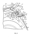
- the rear fender 24 having a license plate 40 attached at the vertically midsection thereof, is integrally provided with a pair of left and right plate mounting portions 41 and 41 to which the upper portion of the license plate 40 is secured with screw members 43 and 43, and the rear fender 24 is integrally formed with a supporting projection 42 for receiving the lower portion of the license plate 40 so as to project from the lower portion of the rear fender 24.
- the upper portion of the rear fender 24 is formed with a recess 24a projecting toward the front and opening toward the rear, and the base member 46 is attached to the rear fender 24 with part thereof accommodated in the recess 24a.
- the base member 46 includes a base body 46a formed into a bottomed cylindrical shape, which is relatively elongated in the fore-and-aft direction, rectangular in lateral cross section, and closed at the rear end, and a overhanging portion 46b, which is overhanging from a base portion of the base body 46a upward and formed into a rectangular cylindrical shape with the rear end closed, and formed integrally with each other of synthetic resin.
- the rear surface of the closed portion at the rear end of the base body 46a is formed as a flat first mounting surface 46c
- the rear surface of the closed portion at the rear end of the overhanging portion 46b is formed as a flat second mounting surface 46d.
- the base 47 is formed of synthetic resin, and the base 47 is secured to the first mounting surface 46c of the base member 46 by inserting a plurality of, for example, a pair of bolts 52 and 52, which are embedded into the base 47 by molding, into the closed end of the rear portion of the base member 46, and screwing nuts 53 and 53 on the bolts 52 and 52 in the base member 46.
- a seal member 53 is interposed between the base 47 and the case 48, and a plurality of, for example, a pair of tap screws 54 ... which are inserted into the case 48, are screwed into the base 47.
- the operation of the first embodiment will be described. Since the license light 44 is mounted to the base member 46, which is attached to the rear fender 24, and then the reflector 45 is also mounted thereto at the position above the license light 44, constraint on configuration of the rear fender 24 may be avoided as much as possible when mounting the reflector 45, and constraint on direction of die-cutting may also be avoided even when the rear fender 24 is formed by molding of synthetic resin, so that the reflector 45 may be commonly used for rear fenders 24 of various motorcycles to expand versatility.
- the reflector 45 is attached to the base member 46, to which the license light 44 is provided on the upper portion thereof, at the position below the license light 44.
- the invention enables a reflector to be mounted to a rear fender without constraining the configuration of the rear fender so as to expand versatility and improve assembly property of the reflector, a license light, and a license plate to the rear fender, in a rear illumination apparatus for a motorcycle including the license plate, the license light for illuminating the license plate, and the reflector mounted on the rear fender covering the upward of the rear portion of a rear wheel.
- a license light 44 is provided on a base member 46, which is to be attached to a rear fender 24, and also a reflector 45 is attached thereto at the position above a license light 44.
Landscapes
- Engineering & Computer Science (AREA)
- Mechanical Engineering (AREA)
- Lighting Device Outwards From Vehicle And Optical Signal (AREA)
- Body Structure For Vehicles (AREA)
Abstract
Description
Claims (2)
- A rear illumination apparatus for a motorcycle comprising: a license plate (40); a license light (44) for illuminating the license plate (40); and a reflector (45) mounted on a rear fender (24) covering upwardly of the rear portion of a rear wheel (WR), characterized in that said license light (44) and said reflector (45) are attached to base members (46, 46') to be mounted on said rear fender (24).
- A rear illumination apparatus for a motorcycle according to Claim 1, characterized in that a recess (24a) opening toward the rear is formed on the upper portion of said rear fender (24), and said base member (46, 46') is attached to said rear fender (24) by accommodating part of said base members (46, 46') into said recess (24a).
Applications Claiming Priority (2)
| Application Number | Priority Date | Filing Date | Title |
|---|---|---|---|
| JP2002133543 | 2002-05-09 | ||
| JP2002133543A JP4052871B2 (en) | 2002-05-09 | 2002-05-09 | Motorcycle rear lighting system |
Publications (3)
| Publication Number | Publication Date |
|---|---|
| EP1361145A2 true EP1361145A2 (en) | 2003-11-12 |
| EP1361145A3 EP1361145A3 (en) | 2009-08-26 |
| EP1361145B1 EP1361145B1 (en) | 2010-10-06 |
Family
ID=29244168
Family Applications (1)
| Application Number | Title | Priority Date | Filing Date |
|---|---|---|---|
| EP03006381A Expired - Lifetime EP1361145B1 (en) | 2002-05-09 | 2003-03-20 | Rear illumination apparatus for motorcycles |
Country Status (4)
| Country | Link |
|---|---|
| EP (1) | EP1361145B1 (en) |
| JP (1) | JP4052871B2 (en) |
| CN (1) | CN1229255C (en) |
| ES (1) | ES2351788T3 (en) |
Cited By (3)
| Publication number | Priority date | Publication date | Assignee | Title |
|---|---|---|---|---|
| CN102161359A (en) * | 2010-02-17 | 2011-08-24 | 本田技研工业株式会社 | Lighting installation structure |
| EP2557025A1 (en) * | 2011-08-11 | 2013-02-13 | Honda Motor Co., Ltd. | Back part structure of body in saddle-ride type vehicle |
| DE102011006044B4 (en) * | 2010-03-31 | 2020-01-30 | Honda Motor Co., Ltd. | Wiring structure of a license plate light for a two-wheel vehicle |
Families Citing this family (14)
| Publication number | Priority date | Publication date | Assignee | Title |
|---|---|---|---|---|
| JP4513464B2 (en) * | 2004-08-31 | 2010-07-28 | スズキ株式会社 | Motorcycle rear fender |
| JP4437952B2 (en) * | 2004-10-12 | 2010-03-24 | 本田技研工業株式会社 | Vehicle tail lamp structure |
| JP4555719B2 (en) * | 2005-03-30 | 2010-10-06 | 本田技研工業株式会社 | Motorcycle rear lighting structure |
| JP5292607B2 (en) * | 2008-01-31 | 2013-09-18 | 本田技研工業株式会社 | Rear lighting system for vehicles |
| JP5040877B2 (en) * | 2008-09-25 | 2012-10-03 | 本田技研工業株式会社 | Support structure for vehicle lighting |
| JP4478195B1 (en) * | 2008-11-28 | 2010-06-09 | ヤマハ発動機株式会社 | Motorcycle |
| JP5478407B2 (en) * | 2009-08-31 | 2014-04-23 | 本田技研工業株式会社 | Motorcycle taillight device |
| JP5460511B2 (en) * | 2010-07-23 | 2014-04-02 | 本田技研工業株式会社 | Rear fender for vehicles |
| CN102442376B (en) * | 2010-09-30 | 2014-04-09 | 本田技研工业株式会社 | Vehicular lighting device and vehicle with same |
| JP5801236B2 (en) * | 2012-03-28 | 2015-10-28 | 本田技研工業株式会社 | Motorcycle lights |
| CN103358986B (en) * | 2012-03-30 | 2015-09-16 | 雅马哈发动机株式会社 | Straddle type vehicle |
| TWI581990B (en) * | 2013-01-30 | 2017-05-11 | Yamaha Motor Co Ltd | Straddle type vehicle |
| CN103963880B (en) * | 2013-01-30 | 2017-03-01 | 雅马哈发动机株式会社 | Straddle type vehicle |
| JP7048758B2 (en) * | 2018-09-28 | 2022-04-05 | 本田技研工業株式会社 | License light for saddle-mounted vehicles |
Family Cites Families (7)
| Publication number | Priority date | Publication date | Assignee | Title |
|---|---|---|---|---|
| US3828178A (en) * | 1973-09-18 | 1974-08-06 | Q Bickel | Taillight assembly |
| US3916377A (en) * | 1974-07-29 | 1975-10-28 | Cycle Sentry Leasing | Vehicle safety warning device |
| US3941994A (en) * | 1974-12-09 | 1976-03-02 | Preston L. Petty | Tail light and fender |
| JPS5849574A (en) * | 1981-09-19 | 1983-03-23 | 本田技研工業株式会社 | Motorcycle |
| JPH0662102B2 (en) * | 1983-12-29 | 1994-08-17 | ヤマハ発動機株式会社 | Front cowling mounting structure for motorcycles |
| JPS61115785A (en) * | 1984-11-13 | 1986-06-03 | ヤマハ発動機株式会社 | Rear fender device for car such as motorcycle |
| JPH0644787Y2 (en) * | 1989-12-05 | 1994-11-16 | 川崎重工業株式会社 | Rear fender device for motorcycles |
-
2002
- 2002-05-09 JP JP2002133543A patent/JP4052871B2/en not_active Expired - Fee Related
-
2003
- 2003-03-20 EP EP03006381A patent/EP1361145B1/en not_active Expired - Lifetime
- 2003-03-20 ES ES03006381T patent/ES2351788T3/en not_active Expired - Lifetime
- 2003-03-25 CN CNB031082173A patent/CN1229255C/en not_active Expired - Lifetime
Cited By (3)
| Publication number | Priority date | Publication date | Assignee | Title |
|---|---|---|---|---|
| CN102161359A (en) * | 2010-02-17 | 2011-08-24 | 本田技研工业株式会社 | Lighting installation structure |
| DE102011006044B4 (en) * | 2010-03-31 | 2020-01-30 | Honda Motor Co., Ltd. | Wiring structure of a license plate light for a two-wheel vehicle |
| EP2557025A1 (en) * | 2011-08-11 | 2013-02-13 | Honda Motor Co., Ltd. | Back part structure of body in saddle-ride type vehicle |
Also Published As
| Publication number | Publication date |
|---|---|
| CN1229255C (en) | 2005-11-30 |
| ES2351788T3 (en) | 2011-02-10 |
| EP1361145A3 (en) | 2009-08-26 |
| EP1361145B1 (en) | 2010-10-06 |
| JP2003320979A (en) | 2003-11-11 |
| CN1456473A (en) | 2003-11-19 |
| JP4052871B2 (en) | 2008-02-27 |
Similar Documents
| Publication | Publication Date | Title |
|---|---|---|
| EP1361145B1 (en) | Rear illumination apparatus for motorcycles | |
| JP5033585B2 (en) | Motorcycle seat rail | |
| US20150266410A1 (en) | Headlight device for motorcycle | |
| JP2009166790A (en) | Flasher and saddle-ride type vehicles | |
| US20200290695A1 (en) | Headlight support structure of saddle riding vehicle | |
| KR100463214B1 (en) | Lamp mounting structure for motorcycle | |
| JP4280501B2 (en) | Front cowl mounting structure for motorcycles | |
| JP2006096233A (en) | Body cover structure for motorcycles | |
| KR100696998B1 (en) | Steering wheel cover device of motorcycle | |
| EP1361144B1 (en) | Headlight apparatus for motorcycles | |
| KR0132256B1 (en) | Til lamp of a car | |
| CN102381393B (en) | Rear structure for motorized two-wheel vehicle | |
| JPH10226375A5 (en) | ||
| JP4546204B2 (en) | Grab rail | |
| CN111605653B (en) | saddle-ridden vehicle | |
| EP1642811B1 (en) | Windscreen mounting structure in light vehicles | |
| JP4391931B2 (en) | Motorcycle seat support structure | |
| JP5912757B2 (en) | Support structure for straddle-type vehicles | |
| CN101954939B (en) | Two-wheeled motor vehicle | |
| WO2020066138A1 (en) | Licence plate light for saddled vehicles | |
| JP2024127041A (en) | Vehicle camera mounting structure | |
| TWI285168B (en) | Vehicular lighting appliance structure | |
| JP7712814B2 (en) | Meter bracket for straddle-type vehicles |
Legal Events
| Date | Code | Title | Description |
|---|---|---|---|
| PUAI | Public reference made under article 153(3) epc to a published international application that has entered the european phase |
Free format text: ORIGINAL CODE: 0009012 |
|
| AK | Designated contracting states |
Kind code of ref document: A2 Designated state(s): AT BE BG CH CY CZ DE DK EE ES FI FR GB GR HU IE IT LI LU MC NL PT RO SE SI SK TR |
|
| AX | Request for extension of the european patent |
Extension state: AL LT LV MK |
|
| PUAL | Search report despatched |
Free format text: ORIGINAL CODE: 0009013 |
|
| AK | Designated contracting states |
Kind code of ref document: A3 Designated state(s): AT BE BG CH CY CZ DE DK EE ES FI FR GB GR HU IE IT LI LU MC NL PT RO SE SI SK TR |
|
| AX | Request for extension of the european patent |
Extension state: AL LT LV MK |
|
| 17P | Request for examination filed |
Effective date: 20091021 |
|
| 17Q | First examination report despatched |
Effective date: 20091201 |
|
| AKX | Designation fees paid |
Designated state(s): ES GB GR |
|
| GRAP | Despatch of communication of intention to grant a patent |
Free format text: ORIGINAL CODE: EPIDOSNIGR1 |
|
| REG | Reference to a national code |
Ref country code: DE Ref legal event code: 8566 |
|
| GRAS | Grant fee paid |
Free format text: ORIGINAL CODE: EPIDOSNIGR3 |
|
| GRAA | (expected) grant |
Free format text: ORIGINAL CODE: 0009210 |
|
| RIN1 | Information on inventor provided before grant (corrected) |
Inventor name: YAMAGUCHI, MASAAKIC/O KABUSHIKI KAISHA HONDA GIJUT Inventor name: TANAKA, JUNC/O KABUSHIKI KAISHA HONDA GIJUTSU KENK Inventor name: OTSUBO, MAMORUC/O KABUSHIKI KAISHA HONDA GIJUTSU K |
|
| AK | Designated contracting states |
Kind code of ref document: B1 Designated state(s): ES GB GR |
|
| REG | Reference to a national code |
Ref country code: GB Ref legal event code: FG4D |
|
| REG | Reference to a national code |
Ref country code: GR Ref legal event code: EP Ref document number: 20100402819 Country of ref document: GR |
|
| REG | Reference to a national code |
Ref country code: ES Ref legal event code: FG2A Effective date: 20110131 |
|
| PLBE | No opposition filed within time limit |
Free format text: ORIGINAL CODE: 0009261 |
|
| STAA | Information on the status of an ep patent application or granted ep patent |
Free format text: STATUS: NO OPPOSITION FILED WITHIN TIME LIMIT |
|
| 26N | No opposition filed |
Effective date: 20110707 |
|
| PGFP | Annual fee paid to national office [announced via postgrant information from national office to epo] |
Ref country code: ES Payment date: 20160211 Year of fee payment: 14 |
|
| PGFP | Annual fee paid to national office [announced via postgrant information from national office to epo] |
Ref country code: GB Payment date: 20160316 Year of fee payment: 14 Ref country code: GR Payment date: 20160212 Year of fee payment: 14 |
|
| REG | Reference to a national code |
Ref country code: GB Ref legal event code: 746 Effective date: 20161026 |
|
| GBPC | Gb: european patent ceased through non-payment of renewal fee |
Effective date: 20170320 |
|
| PG25 | Lapsed in a contracting state [announced via postgrant information from national office to epo] |
Ref country code: GR Free format text: LAPSE BECAUSE OF NON-PAYMENT OF DUE FEES Effective date: 20171005 Ref country code: GB Free format text: LAPSE BECAUSE OF NON-PAYMENT OF DUE FEES Effective date: 20170320 |
|
| REG | Reference to a national code |
Ref country code: ES Ref legal event code: FD2A Effective date: 20180704 |
|
| PG25 | Lapsed in a contracting state [announced via postgrant information from national office to epo] |
Ref country code: ES Free format text: LAPSE BECAUSE OF NON-PAYMENT OF DUE FEES Effective date: 20170321 |