EP1361118A2 - Apparatus for controlling vehicle - Google Patents
Apparatus for controlling vehicle Download PDFInfo
- Publication number
- EP1361118A2 EP1361118A2 EP03009786A EP03009786A EP1361118A2 EP 1361118 A2 EP1361118 A2 EP 1361118A2 EP 03009786 A EP03009786 A EP 03009786A EP 03009786 A EP03009786 A EP 03009786A EP 1361118 A2 EP1361118 A2 EP 1361118A2
- Authority
- EP
- European Patent Office
- Prior art keywords
- vehicle
- range
- sensors
- controlling
- sensor
- Prior art date
- Legal status (The legal status is an assumption and is not a legal conclusion. Google has not performed a legal analysis and makes no representation as to the accuracy of the status listed.)
- Withdrawn
Links
Images


Classifications
-
- G—PHYSICS
- G01—MEASURING; TESTING
- G01S—RADIO DIRECTION-FINDING; RADIO NAVIGATION; DETERMINING DISTANCE OR VELOCITY BY USE OF RADIO WAVES; LOCATING OR PRESENCE-DETECTING BY USE OF THE REFLECTION OR RERADIATION OF RADIO WAVES; ANALOGOUS ARRANGEMENTS USING OTHER WAVES
- G01S13/00—Systems using the reflection or reradiation of radio waves, e.g. radar systems; Analogous systems using reflection or reradiation of waves whose nature or wavelength is irrelevant or unspecified
- G01S13/87—Combinations of radar systems, e.g. primary radar and secondary radar
-
- G—PHYSICS
- G01—MEASURING; TESTING
- G01S—RADIO DIRECTION-FINDING; RADIO NAVIGATION; DETERMINING DISTANCE OR VELOCITY BY USE OF RADIO WAVES; LOCATING OR PRESENCE-DETECTING BY USE OF THE REFLECTION OR RERADIATION OF RADIO WAVES; ANALOGOUS ARRANGEMENTS USING OTHER WAVES
- G01S13/00—Systems using the reflection or reradiation of radio waves, e.g. radar systems; Analogous systems using reflection or reradiation of waves whose nature or wavelength is irrelevant or unspecified
- G01S13/88—Radar or analogous systems specially adapted for specific applications
- G01S13/93—Radar or analogous systems specially adapted for specific applications for anti-collision purposes
- G01S13/931—Radar or analogous systems specially adapted for specific applications for anti-collision purposes of land vehicles
-
- B—PERFORMING OPERATIONS; TRANSPORTING
- B60—VEHICLES IN GENERAL
- B60R—VEHICLES, VEHICLE FITTINGS, OR VEHICLE PARTS, NOT OTHERWISE PROVIDED FOR
- B60R21/00—Arrangements or fittings on vehicles for protecting or preventing injuries to occupants or pedestrians in case of accidents or other traffic risks
- B60R21/01—Electrical circuits for triggering passive safety arrangements, e.g. airbags, safety belt tighteners, in case of vehicle accidents or impending vehicle accidents
- B60R21/013—Electrical circuits for triggering passive safety arrangements, e.g. airbags, safety belt tighteners, in case of vehicle accidents or impending vehicle accidents including means for detecting collisions, impending collisions or roll-over
- B60R21/0134—Electrical circuits for triggering passive safety arrangements, e.g. airbags, safety belt tighteners, in case of vehicle accidents or impending vehicle accidents including means for detecting collisions, impending collisions or roll-over responsive to imminent contact with an obstacle, e.g. using radar systems
-
- G—PHYSICS
- G01—MEASURING; TESTING
- G01S—RADIO DIRECTION-FINDING; RADIO NAVIGATION; DETERMINING DISTANCE OR VELOCITY BY USE OF RADIO WAVES; LOCATING OR PRESENCE-DETECTING BY USE OF THE REFLECTION OR RERADIATION OF RADIO WAVES; ANALOGOUS ARRANGEMENTS USING OTHER WAVES
- G01S13/00—Systems using the reflection or reradiation of radio waves, e.g. radar systems; Analogous systems using reflection or reradiation of waves whose nature or wavelength is irrelevant or unspecified
- G01S13/88—Radar or analogous systems specially adapted for specific applications
- G01S13/93—Radar or analogous systems specially adapted for specific applications for anti-collision purposes
- G01S13/931—Radar or analogous systems specially adapted for specific applications for anti-collision purposes of land vehicles
- G01S2013/932—Radar or analogous systems specially adapted for specific applications for anti-collision purposes of land vehicles using own vehicle data, e.g. ground speed, steering wheel direction
-
- G—PHYSICS
- G01—MEASURING; TESTING
- G01S—RADIO DIRECTION-FINDING; RADIO NAVIGATION; DETERMINING DISTANCE OR VELOCITY BY USE OF RADIO WAVES; LOCATING OR PRESENCE-DETECTING BY USE OF THE REFLECTION OR RERADIATION OF RADIO WAVES; ANALOGOUS ARRANGEMENTS USING OTHER WAVES
- G01S13/00—Systems using the reflection or reradiation of radio waves, e.g. radar systems; Analogous systems using reflection or reradiation of waves whose nature or wavelength is irrelevant or unspecified
- G01S13/88—Radar or analogous systems specially adapted for specific applications
- G01S13/93—Radar or analogous systems specially adapted for specific applications for anti-collision purposes
- G01S13/931—Radar or analogous systems specially adapted for specific applications for anti-collision purposes of land vehicles
- G01S2013/9323—Alternative operation using light waves
-
- G—PHYSICS
- G01—MEASURING; TESTING
- G01S—RADIO DIRECTION-FINDING; RADIO NAVIGATION; DETERMINING DISTANCE OR VELOCITY BY USE OF RADIO WAVES; LOCATING OR PRESENCE-DETECTING BY USE OF THE REFLECTION OR RERADIATION OF RADIO WAVES; ANALOGOUS ARRANGEMENTS USING OTHER WAVES
- G01S13/00—Systems using the reflection or reradiation of radio waves, e.g. radar systems; Analogous systems using reflection or reradiation of waves whose nature or wavelength is irrelevant or unspecified
- G01S13/88—Radar or analogous systems specially adapted for specific applications
- G01S13/93—Radar or analogous systems specially adapted for specific applications for anti-collision purposes
- G01S13/931—Radar or analogous systems specially adapted for specific applications for anti-collision purposes of land vehicles
- G01S2013/9327—Sensor installation details
- G01S2013/93271—Sensor installation details in the front of the vehicles
-
- G—PHYSICS
- G01—MEASURING; TESTING
- G01S—RADIO DIRECTION-FINDING; RADIO NAVIGATION; DETERMINING DISTANCE OR VELOCITY BY USE OF RADIO WAVES; LOCATING OR PRESENCE-DETECTING BY USE OF THE REFLECTION OR RERADIATION OF RADIO WAVES; ANALOGOUS ARRANGEMENTS USING OTHER WAVES
- G01S13/00—Systems using the reflection or reradiation of radio waves, e.g. radar systems; Analogous systems using reflection or reradiation of waves whose nature or wavelength is irrelevant or unspecified
- G01S13/88—Radar or analogous systems specially adapted for specific applications
- G01S13/93—Radar or analogous systems specially adapted for specific applications for anti-collision purposes
- G01S13/931—Radar or analogous systems specially adapted for specific applications for anti-collision purposes of land vehicles
- G01S2013/9327—Sensor installation details
- G01S2013/93272—Sensor installation details in the back of the vehicles
-
- G—PHYSICS
- G01—MEASURING; TESTING
- G01S—RADIO DIRECTION-FINDING; RADIO NAVIGATION; DETERMINING DISTANCE OR VELOCITY BY USE OF RADIO WAVES; LOCATING OR PRESENCE-DETECTING BY USE OF THE REFLECTION OR RERADIATION OF RADIO WAVES; ANALOGOUS ARRANGEMENTS USING OTHER WAVES
- G01S13/00—Systems using the reflection or reradiation of radio waves, e.g. radar systems; Analogous systems using reflection or reradiation of waves whose nature or wavelength is irrelevant or unspecified
- G01S13/88—Radar or analogous systems specially adapted for specific applications
- G01S13/93—Radar or analogous systems specially adapted for specific applications for anti-collision purposes
- G01S13/931—Radar or analogous systems specially adapted for specific applications for anti-collision purposes of land vehicles
- G01S2013/9327—Sensor installation details
- G01S2013/93274—Sensor installation details on the side of the vehicles
-
- G—PHYSICS
- G01—MEASURING; TESTING
- G01S—RADIO DIRECTION-FINDING; RADIO NAVIGATION; DETERMINING DISTANCE OR VELOCITY BY USE OF RADIO WAVES; LOCATING OR PRESENCE-DETECTING BY USE OF THE REFLECTION OR RERADIATION OF RADIO WAVES; ANALOGOUS ARRANGEMENTS USING OTHER WAVES
- G01S13/00—Systems using the reflection or reradiation of radio waves, e.g. radar systems; Analogous systems using reflection or reradiation of waves whose nature or wavelength is irrelevant or unspecified
- G01S13/88—Radar or analogous systems specially adapted for specific applications
- G01S13/93—Radar or analogous systems specially adapted for specific applications for anti-collision purposes
- G01S13/931—Radar or analogous systems specially adapted for specific applications for anti-collision purposes of land vehicles
- G01S2013/9327—Sensor installation details
- G01S2013/93277—Sensor installation details in the lights
Definitions
- the present invention relates to an apparatus for carrying out vehicle control, i.e., safety control, by utilizing signals from a plurality of range sensors. More particularly, the present invention relates to an apparatus for controlling a vehicle including a plurality of range sensors, which can make control using some of the signals from the plurality of range sensors with priority and can realize proper control.
- an obstacle sensor for a vehicle disclosed in Japanese Unexamined Patent Application Publication No. 10-282233.
- an obstacle around a vehicle is detected by two front and two rear obstacle sensing means capable of detecting the direction of and the distance to the obstacle, and when the obstacle is detected, a voice generating means is operated to notify a driver of a warning.
- the voice generating means disposed in a direction oriented to the detected obstacle is operated to notify the driver of a warning from the direction of the detected obstacle. Accordingly, the driver can surely recognize the direction of the detected obstacle.
- the above-cited publication disclosing the obstacle sensor for the vehicle which has the structure described above, includes no suggestions regarding a priority process of signals from the obstacle sensing means.
- a disadvantage occurs in that proper ones of the obstacle sensing means cannot be utilized depending on various situations.
- the vehicle running on a curved road for example, if an obstacle around the vehicle is detected using the signals from all of the obstacle sensing means as with the case of the vehicle running on a straight road, there is a limit in cutting down a time from the detection of an obstacle to issuance of a warning to the driver.
- an object of the present invention to provide an apparatus for controlling a vehicle, which can perform proper vehicle control and can issue a proper warning without causing abrupt behaviors of a vehicle. Another object is to provide an apparatus for controlling a vehicle, which can perform proper vehicle control and can ensure stable running while the vehicle is running on not only a straight road, but also a curved road.
- the present invention can provides an apparatus for controlling a vehicle which may comprise at least one range sensor installed in an outer peripheral portion of a vehicle for sensing a target object including another vehicle, comprising a controller for carrying out control using, of signals outputted from the at least one range sensor, a signal from at least one range sensor with priority, which is neither failed nor deteriorated in sensor characteristics.
- the range sensors may be installed in upper and lower portions of the vehicle as an occasion requires.
- the present invention provides an apparatus for controlling a vehicle which may comprise at least one range sensor installed in an outer peripheral portion of a vehicle for sensing a target object including another vehicle, comprising a controller for carrying out control using, of signals outputted from the at least one range sensor, a signal from at least one range sensor with priority, which is positioned on the same side as a direction of turn of a steering wheel, when processing the signals from the range sensors installed in front and rear portions of the vehicle.
- the control is carried out using the signal from at least one range sensor with priority, which is positioned on the same side as the direction of turn of the steering wheel.
- a target object positioned ahead of or behind the vehicle can be detected in a shorter time. Therefore, a danger such as a collision can be avoided with proper control and safety of the driver in the event of a collision can be improved, whereby stable running can be achieved.
- the present invention provides an apparatus for controlling a vehicle which can comprise at least one range sensor installed in an outer peripheral portion of a vehicle for sensing a target object including another vehicle, comprising a controller for carrying out control using, of signals outputted from the at least one range sensor, a signal from at least one range sensor with priority, which has detected a shorter distance from the target object, when processing the signals from the range sensors installed on both lateral sides of the vehicle.
- a target object such as another oncoming vehicle positioned laterally of the relevant vehicle, can be quickly detected to carry out prompt control.
- safety in the event of a collision in the lateral direction of the vehicle can be improved and stable running can be achieved.
- the present invention provides an apparatus for controlling a vehicle which can comprise at least one range sensor installed in an outer peripheral portion of a vehicle for sensing a target object including another vehicle, comprising a controller for carrying out control using, of signals outputted from the at least one range sensor, a signal from at least one range sensor with priority, which is installed on the lateral side of the vehicle nearer to a lane to which the vehicle is going to move, when the vehicle changes a lane.
- the control is carried out using the range sensor positioned nearer to the lane to which the vehicle is going to move.
- another vehicle running in the same direction side by side can be quickly detected and safety in the event of a collision in the lateral direction can be improved, whereby stable running can be achieved.
- the vehicle includes a vehicle speed sensor, ones of the plurality of range sensors, which are installed in a front portion of the vehicle, comprise a far-range sensor and a near-range sensor, and the controller includes a switchover unit for switching over the far-range sensor and the near-range sensor from one to the other depending on an output signal of the vehicle speed sensor when processing the signals from the plurality of range sensors.
- the range sensors installed in the front and rear portions of the vehicle are built in headlamps and tail lamps.
- the range sensors can be installed with a simpler construction, and the operation is stabilized because the range sensors are kept from being directly exposed to wind, rain, etc.
- the range sensors are preferably optical sensors, radar sensors, or infrared sensors. As a result, the distance between the vehicle and another target object can be detected with high accuracy and the operation is stabilized.
- a warning is issued to a driver when another target object comes into a danger detection area preset for the range sensors.
- the warning be issued to the driver using sound, light, vibration, or any suitable combination thereof.
- Fig. 1 is a schematic plan view of a first example of a vehicle in which a plurality of range sensors constituting the embodiment of the apparatus for controlling the vehicle are installed.
- a vehicle 50 includes a far-range sensor 1 installed in its front central portion, and far-range sensors 1A, 1B installed respectively on the right and left sides adjacent to headlamps 10, 11.
- a far-range sensor 8 is installed at the center and near-range sensors 4, 5 are installed respectively on the right and left sides.
- near-range sensors 6, 7 are installed in respective side mirrors 21, 22.
- the term "far-range sensor” means a sensor capable of detecting a far distance with a small detection angle
- the term “near-range sensor” means a sensor adaptable for detecting a short distance with a large detection angle (see Fig. 4).
- Those range sensors may be each of any suitable type, for example, employing an ultrasonic wave and measuring the distance based on a time taken for a reflected wave from a target object to reach the vehicle, or employing a millimeter (extremely high frequency) wave radar sensor in the band of 76 GHz.
- the arrangement of the plurality of range sensors may be modified as follows. More specifically, as shown in Fig. 2, near-range sensors 2, 3 may be installed respectively on the right and left sides in the front portion of vehicle with the far-range sensor 1 remaining installed at the center. Alternatively, as shown in Fig. 3, the far-range sensors 1A, 1B may be built in the respective headlamps 10, 11. This arrangement is advantageous in that reliability is not affected by weather, e.g., rain. A similar advantage can be obtained by installing the range sensors 4, 5 to be built in respective tail lamps (though not shown). Further, by operating wipers (not shown) attached to the headlamps 10, 11 in some of high-class vehicles, it is possible to suppress a reduction in accuracy of range detection caused by rain or snow. Alternatively, as shown in Fig. 4, near-range sensors 2A, 2B may be built in the respective headlamps 10, 11.
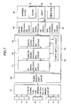
- a signal processing circuit constituting the apparatus for controlling the vehicle in combination with the plurality of range sensors will be described with reference to Fig. 5.
- Signals from the plurality of range sensors 1, 1A, 1B and 4 to 8 are inputted to a sensor signal failure/deterioration determining circuit 70, which allows only normal signals to be inputted to a sensor circuit 80.
- the determining circuit 70 has a function of selecting optimum ones of the plurality of range sensors.
- the selected signals are outputted from the sensor circuit 80 to a front signal processing circuit 85, a rear signal processing circuit 86 and a side signal processing circuit 87, and then employed for respective control processes.
- the sensor circuit 80 comprises an RF signal processing circuit 81, an analog signal processing circuit 82, a digital signal processing circuit 83, and a power supply circuit 84. Signals from the sensor signal failure/deterioration determining circuit 70 are inputted to the RF signal processing circuit 81, and then inputted to the analog signal processing circuit 82 and the digital signal processing circuit 83 in sequence. The signals processed in those circuits are returned to the RF signal processing circuit 81.
- the power supply circuit 84 supplies voltages to the circuits 81, 82 and 83.
- Outputs from the front signal processing circuit 85, the rear signal processing circuit 86 and the side signal processing circuit 87 are inputted to a warning device 90.
- the warning device 90 is designed so as to generate sound 91, light 92 or vibration 93 and issue a warning to the driver when a target object, e.g., another vehicle, has come into or close to a danger detection area preset for the range sensors.
- the warning device 90 may issue a warning in any suitable combination of the sound 91, the light 92 and the vibration 93.
- Main purposes for installing the plurality of range sensors in the vehicle as shown in Fig. 1 are to avoid a collision and to ensure safety in the event of a collision. In other words, even if a collision should be unavoidable, the vehicle must be controlled such that it collides against another vehicle from a safer direction. However, there occurs a mechanical time delay, after the detection, until a control signal is produced and the vehicle behavior is actually performed.
- the three front range sensors 1, 1A and 1B are installed as shown in Fig. 1 and, if sensor signals from those three sensors are all normal, the sensor signal failure/deterioration determining circuit 70 selects the range sensor 1A on the same side as a steering wheel, and control is carried out using the signal, which has been selected with priority, thereby ensuring safety of the driver in the event of a collision. If the range sensor 1A on the same side as the steering wheel is failed, control is carried out using the range sensor 1 nearer to the driver with priority without using the range sensor 1B.
- the near-range sensors 1A, 6 and 4 are installed on the right side of the vehicle and the near-range sensors 1B, 7 and 5 are installed on the left side as viewed in the running direction of the vehicle, if another vehicle approaches the relevant vehicle from the right in a perpendicular direction and the near-range sensors 1A, 6 and 4 are all normal, control is carried out using signals from the near-range sensors 1A, 6 and 4 on the side closer to another approaching vehicle with priority for cutting down the time required for determination to start the control to avoid a collision.
- the warning device 90 issues a warning to the driver using the sound 91, the light 92 and the vibration 93 as shown in Fig. 5.
- the driver applies the brakes for deceleration and performs urgent steering to avoid a danger.
- Fig. 7 is a block diagram of a signal processing circuit incorporated in the apparatus for controlling the vehicle according to the present invention and used in the vehicle of Fig. 2. Comparing with the above embodiment, this embodiment is featured in that a signal switchover circuit 100 is inserted after the sensor signal failure/deterioration determining circuit 70. Other essentially identical components are denoted by the same reference numerals and are not described here.
- signals from the far-range sensor 1 and the near-range sensors 2, 3 installed in the front portion of the vehicle 50 are selectively inputted depending on a signal from a vehicle speed sensor. More specifically, as shown in Fig. 7, the signal switchover circuit 100 for switching over signals depending on the vehicle speed is inserted after the sensor signal failure/deterioration determining circuit 70, and the selected one or more signals are inputted to the sensor circuit 80.
- the sensor signal failure/deterioration determining circuit 70 selects the far-range sensor 1, which is used for control with priority. Hence, an allowance is given to the time taken to avoid a collision. Also, when the vehicle speed is low, the near-range sensors 2, 3 are used for control with priority. Accordingly, the distance between the vehicle 50 and the target object, such as another vehicle or an obstacle, can be detected with high accuracy and the determination to start the control to avoid a collision can be made with higher reliability.
- the far-range sensors 1, 8 and the near-range sensors 2 to 7 are failed or their sensing characteristics are deteriorated
- signals from only the far-range sensors, which are neither failed nor deteriorated are selected by the sensor signal failure/deterioration determining circuit 70 and are used for control with priority.
- the signal processing is executed to carry out control using the signals from the far-range sensors installed nearer to the steering wheel with priority.
- control is carried out using the signal of the range sensor with priority, which has sensed a shorter detection distance from a target object locating around the vehicle.
- the signal processing is executed to carry out control using the signal from the range sensor installed on the lateral side nearer to a lane, to which the vehicle is going to move, with priority.
- the near-range sensors 6, 7 are installed respectively in the side mirrors 21, 22.
- the object of the present invention can be achieved without the near-range sensors installed in the side mirrors.
- the range sensors used in the present invention may be optical sensors.
- infrared sensors for detecting animals at night may be used.
- those different types of sensors may be used in combination.
- the sensor signals may also be switched over depending on the vehicle speed.
- the sensor signals are switched over, for example, such that when the vehicle speed is high, the far-range sensor 1 at the center is used with priority to carry out control, and when the vehicle speed is low, the far-range sensors 1A, 1B on the right and left sides are used with priority to carry out control.
- the apparatus for controlling the vehicle of the present invention when a plurality of range sensors are employed, proper one or more of signals outputted from the plurality of range sensors are selected and used with priority for signal processing to carry out control. Therefore, vehicle control and issuance of a warning to the driver can be more quickly and more accurately performed. As a result, it is possible to provide an apparatus for controlling a vehicle, which can prevent a collision and ensure stable running without needing abrupt steering and abrupt braking.
Landscapes
- Engineering & Computer Science (AREA)
- Radar, Positioning & Navigation (AREA)
- Remote Sensing (AREA)
- Physics & Mathematics (AREA)
- Computer Networks & Wireless Communication (AREA)
- General Physics & Mathematics (AREA)
- Electromagnetism (AREA)
- Traffic Control Systems (AREA)
- Control Of Driving Devices And Active Controlling Of Vehicle (AREA)
- Radar Systems Or Details Thereof (AREA)
Abstract
Description
- The present invention relates to an apparatus for carrying out vehicle control, i.e., safety control, by utilizing signals from a plurality of range sensors. More particularly, the present invention relates to an apparatus for controlling a vehicle including a plurality of range sensors, which can make control using some of the signals from the plurality of range sensors with priority and can realize proper control.
- As that type of obstacle sensor for a vehicle, there is known an obstacle sensor for a vehicle disclosed in Japanese Unexamined Patent Application Publication No. 10-282233. With the disclosed obstacle sensor, an obstacle around a vehicle is detected by two front and two rear obstacle sensing means capable of detecting the direction of and the distance to the obstacle, and when the obstacle is detected, a voice generating means is operated to notify a driver of a warning. On that occasion, the voice generating means disposed in a direction oriented to the detected obstacle is operated to notify the driver of a warning from the direction of the detected obstacle. Accordingly, the driver can surely recognize the direction of the detected obstacle.
- However, the above-cited publication disclosing the obstacle sensor for the vehicle, which has the structure described above, includes no suggestions regarding a priority process of signals from the obstacle sensing means. In other words, if the technique disclosed in the above-cited publication is directly applied to the vehicle, a disadvantage occurs in that proper ones of the obstacle sensing means cannot be utilized depending on various situations. In the case of the vehicle running on a curved road, for example, if an obstacle around the vehicle is detected using the signals from all of the obstacle sensing means as with the case of the vehicle running on a straight road, there is a limit in cutting down a time from the detection of an obstacle to issuance of a warning to the driver.
- Further, when characteristics of any of the obstacle sensing means are deteriorated, problems arise in that cutting-down of the time until the issuance of a warning is limited and, in the worst case, it becomes impossible to issue a warning itself. Those problems cause a delay in vehicle control. In other words, a delay in detection causes a delay in automatic vehicle control, and a delay in issuance of a warning causes a delay in manual vehicle control. Accordingly, abrupt steering and abrupt braking are necessitated.
- In view of the problems set forth above, it is an object of the present invention to provide an apparatus for controlling a vehicle, which can perform proper vehicle control and can issue a proper warning without causing abrupt behaviors of a vehicle. Another object is to provide an apparatus for controlling a vehicle, which can perform proper vehicle control and can ensure stable running while the vehicle is running on not only a straight road, but also a curved road.
- To achieve the above object, according to one aspect, the present invention can provides an apparatus for controlling a vehicle which may comprise at least one range sensor installed in an outer peripheral portion of a vehicle for sensing a target object including another vehicle, comprising a controller for carrying out control using, of signals outputted from the at least one range sensor, a signal from at least one range sensor with priority, which is neither failed nor deteriorated in sensor characteristics. The range sensors may be installed in upper and lower portions of the vehicle as an occasion requires.
- With that feature, because of the control being carried out using the signal from at least one range sensor with priority, which is neither failed nor deteriorated in sensor characteristics, even when any of the range sensors is failed, for example, another suitable range sensor can be used instead to take an action to avoid a collision. Further, since the control is carried out using the signal from at least one range sensor with priority, which is not deteriorated in sensor characteristics, a target object positioned around the vehicle can be accurately detected in a shorter time. Hence, a danger such as a collision can be avoided with proper control and stable running can be achieved without causing abrupt behaviors of the vehicle.
- According to another aspect, the present invention provides an apparatus for controlling a vehicle which may comprise at least one range sensor installed in an outer peripheral portion of a vehicle for sensing a target object including another vehicle, comprising a controller for carrying out control using, of signals outputted from the at least one range sensor, a signal from at least one range sensor with priority, which is positioned on the same side as a direction of turn of a steering wheel, when processing the signals from the range sensors installed in front and rear portions of the vehicle. With that feature, when controlling the vehicle using the range sensors installed in the front and rear portions of the vehicle, the control is carried out using the signal from at least one range sensor with priority, which is positioned on the same side as the direction of turn of the steering wheel. Therefore, a target object positioned ahead of or behind the vehicle can be detected in a shorter time. Hence, a danger such as a collision can be avoided with proper control and safety of the driver in the event of a collision can be improved, whereby stable running can be achieved.
- According to still another aspect, the present invention provides an apparatus for controlling a vehicle which can comprise at least one range sensor installed in an outer peripheral portion of a vehicle for sensing a target object including another vehicle, comprising a controller for carrying out control using, of signals outputted from the at least one range sensor, a signal from at least one range sensor with priority, which has detected a shorter distance from the target object, when processing the signals from the range sensors installed on both lateral sides of the vehicle. With that feature, a target object, such as another oncoming vehicle positioned laterally of the relevant vehicle, can be quickly detected to carry out prompt control. Hence, safety in the event of a collision in the lateral direction of the vehicle can be improved and stable running can be achieved.
- According to still another aspect, the present invention provides an apparatus for controlling a vehicle which can comprise at least one range sensor installed in an outer peripheral portion of a vehicle for sensing a target object including another vehicle, comprising a controller for carrying out control using, of signals outputted from the at least one range sensor, a signal from at least one range sensor with priority, which is installed on the lateral side of the vehicle nearer to a lane to which the vehicle is going to move, when the vehicle changes a lane. With that feature, when the vehicle changes a lane, the control is carried out using the range sensor positioned nearer to the lane to which the vehicle is going to move. During the lane change, therefore, another vehicle running in the same direction side by side can be quickly detected and safety in the event of a collision in the lateral direction can be improved, whereby stable running can be achieved.
- In one preferred specific form of the apparatus for controlling the vehicle of the present invention, the vehicle includes a vehicle speed sensor, ones of the plurality of range sensors, which are installed in a front portion of the vehicle, comprise a far-range sensor and a near-range sensor, and the controller includes a switchover unit for switching over the far-range sensor and the near-range sensor from one to the other depending on an output signal of the vehicle speed sensor when processing the signals from the plurality of range sensors. With those features, a time required for determination to start the control to avoid a collision can be cut down, for example, by carrying out the control using the far-range sensor when the vehicle speed is high, and using the near-range sensor when the vehicle speed is low. As a result, stable control can be achieved.
- In another preferred specific form of the apparatus for controlling the vehicle of the present invention, the range sensors installed in the front and rear portions of the vehicle are built in headlamps and tail lamps. With that feature, the range sensors can be installed with a simpler construction, and the operation is stabilized because the range sensors are kept from being directly exposed to wind, rain, etc. The range sensors are preferably optical sensors, radar sensors, or infrared sensors. As a result, the distance between the vehicle and another target object can be detected with high accuracy and the operation is stabilized.
- In the above apparatus for controlling the vehicle, preferably, a warning is issued to a driver when another target object comes into a danger detection area preset for the range sensors. Practically, it is preferable that the warning be issued to the driver using sound, light, vibration, or any suitable combination thereof. With those features, since the warning is issued to the driver using sound, light, vibration, or any suitable combination thereof when another target object comes into the danger detection area, the driver can take an action to avoid a danger, such as a collision, with safety based on the warning.
-
- Fig. 1 is a schematic plan view of a first example of a vehicle in which a plurality of range sensors constituting an apparatus for controlling a vehicle of the present invention are installed;
- Fig. 2 is a schematic plan view of a second example of the vehicle in which a plurality of range sensors are installed;
- Fig. 3 is a schematic plan view of a third example of the vehicle in which a plurality of range sensors are installed;
- Fig. 4 is a schematic plan view of a fourth example of the vehicle in which a plurality of range sensors are installed;
- Fig. 5 is a block diagram of a signal processing circuit used in the vehicle of Fig. 1;
- Fig. 6 shows an operative state of the range sensors when the vehicle of Fig. 1 changes a lane to the right; and
- Fig. 7 is a block diagram of a signal processing circuit used in the vehicle of Fig. 2 and switching over signals depending on a vehicle speed.
-
- A preferred embodiment of an apparatus for controlling a vehicle according to the present invention will be described below in detail with reference to the accompanying drawings. Fig. 1 is a schematic plan view of a first example of a vehicle in which a plurality of range sensors constituting the embodiment of the apparatus for controlling the vehicle are installed. In Fig. 1, a
vehicle 50 includes a far-range sensor 1 installed in its front central portion, and far-range sensors headlamps vehicle 50, as in the front portion, a far-range sensor 8 is installed at the center and near-range sensors - Further, near-
range sensors respective side mirrors range sensors - The arrangement of the plurality of range sensors may be modified as follows. More specifically, as shown in Fig. 2, near-
range sensors range sensor 1 remaining installed at the center. Alternatively, as shown in Fig. 3, the far-range sensors respective headlamps range sensors headlamps range sensors 2A, 2B may be built in therespective headlamps - Next, a signal processing circuit constituting the apparatus for controlling the vehicle in combination with the plurality of range sensors will be described with reference to Fig. 5. Signals from the plurality of
range sensors deterioration determining circuit 70, which allows only normal signals to be inputted to asensor circuit 80. Also, the determiningcircuit 70 has a function of selecting optimum ones of the plurality of range sensors. The selected signals are outputted from thesensor circuit 80 to a frontsignal processing circuit 85, a rearsignal processing circuit 86 and a sidesignal processing circuit 87, and then employed for respective control processes. - The
sensor circuit 80 comprises an RFsignal processing circuit 81, an analogsignal processing circuit 82, a digitalsignal processing circuit 83, and apower supply circuit 84. Signals from the sensor signal failure/deterioration determining circuit 70 are inputted to the RFsignal processing circuit 81, and then inputted to the analogsignal processing circuit 82 and the digitalsignal processing circuit 83 in sequence. The signals processed in those circuits are returned to the RFsignal processing circuit 81. Thepower supply circuit 84 supplies voltages to thecircuits - Outputs from the front
signal processing circuit 85, the rearsignal processing circuit 86 and the sidesignal processing circuit 87 are inputted to awarning device 90. Thewarning device 90 is designed so as to generatesound 91, light 92 orvibration 93 and issue a warning to the driver when a target object, e.g., another vehicle, has come into or close to a danger detection area preset for the range sensors. As an alternative, thewarning device 90 may issue a warning in any suitable combination of the sound 91, the light 92 and thevibration 93. - The operation of the apparatus for controlling the vehicle of this embodiment, having the above-described construction, will be described below. Main purposes for installing the plurality of range sensors in the vehicle as shown in Fig. 1 are to avoid a collision and to ensure safety in the event of a collision. In other words, even if a collision should be unavoidable, the vehicle must be controlled such that it collides against another vehicle from a safer direction. However, there occurs a mechanical time delay, after the detection, until a control signal is produced and the vehicle behavior is actually performed.
- Assuming, for example, that the relative speed is 60 km/h, a distance of 3 m is converted into a time of 180 ms. This means that the control from the detection to the vehicle behavior must be carried out within 180 ms after the vehicle has come into an area corresponding to 3 m. To ensure safety in the event of a collision, it is essential to cut down the mechanical time delay. In addition, cutting down a time required for the detection is also essential. Stated otherwise, it is important to confirm the behavior of another oncoming vehicle before the collision and, particularly in the case of a side collision in which a collision energy absorber is insufficient, to make control for reducing collision damages upon the driver and other passengers within a time of about 30 ms that represents a period from collision detection to actuation of an air bag currently equipped as a collision safety device.
- In view of the above, the three
front range sensors deterioration determining circuit 70 selects therange sensor 1A on the same side as a steering wheel, and control is carried out using the signal, which has been selected with priority, thereby ensuring safety of the driver in the event of a collision. If therange sensor 1A on the same side as the steering wheel is failed, control is carried out using therange sensor 1 nearer to the driver with priority without using therange sensor 1B. - Through such signal processing, as shown in Fig. 6, when the vehicle changes a lane, control is carried out using the range sensors installed on the side closer to the lane, to which the vehicle is going to move, with priority. As a result, the signal processing time can be cut down and safety in the lateral direction is improved. For example, when the vehicle changes a lane to a right one, the
range sensors range sensors - Particularly, safety in the lateral direction is important. On condition that the near-
range sensors range sensors range sensors range sensors - For ensuring safety in the event of a collision, it is important to notify the driver of a signal indicating a dangerous situation around the vehicle. Therefore, when another vehicle has come into or close to a danger detection area preset for the range sensors, the
warning device 90 issues a warning to the driver using thesound 91, the light 92 and thevibration 93 as shown in Fig. 5. In response to the issued warning, the driver applies the brakes for deceleration and performs urgent steering to avoid a danger. - Next, another embodiment of the present invention will be described below with reference to Fig. 7. Fig. 7 is a block diagram of a signal processing circuit incorporated in the apparatus for controlling the vehicle according to the present invention and used in the vehicle of Fig. 2. Comparing with the above embodiment, this embodiment is featured in that a
signal switchover circuit 100 is inserted after the sensor signal failure/deterioration determining circuit 70. Other essentially identical components are denoted by the same reference numerals and are not described here. - Referring to Fig. 7, when the far-
range sensor 1 and the near-range sensors vehicle 50 as shown in Fig. 2, signals from the far-range sensor 1 and the near-range sensors vehicle 50 are selectively inputted depending on a signal from a vehicle speed sensor. More specifically, as shown in Fig. 7, thesignal switchover circuit 100 for switching over signals depending on the vehicle speed is inserted after the sensor signal failure/deterioration determining circuit 70, and the selected one or more signals are inputted to thesensor circuit 80. - In this embodiment, when the
vehicle 50 is running at a high speed, for example, the sensor signal failure/deterioration determining circuit 70 selects the far-range sensor 1, which is used for control with priority. Hence, an allowance is given to the time taken to avoid a collision. Also, when the vehicle speed is low, the near-range sensors vehicle 50 and the target object, such as another vehicle or an obstacle, can be detected with high accuracy and the determination to start the control to avoid a collision can be made with higher reliability. - Also in this embodiment, when any of the far-
range sensors range sensors 2 to 7 are failed or their sensing characteristics are deteriorated, signals from only the far-range sensors, which are neither failed nor deteriorated, are selected by the sensor signal failure/deterioration determining circuit 70 and are used for control with priority. Further, when processing the signals from therange sensors 1 to 3, 4, 5 and 8 are in stalled in the front and rear portions of the vehicle, the signal processing is executed to carry out control using the signals from the far-range sensors installed nearer to the steering wheel with priority. - When processing the signals from the
range sensors - This embodiment of the present invention has been described above in connection with the example, shown in Fig. 2, in which the near-
range sensors range sensors - In another example in which the far-
range sensors vehicle 50 in addition to the far-range sensor 1, the sensor signals may also be switched over depending on the vehicle speed. In this case, the sensor signals are switched over, for example, such that when the vehicle speed is high, the far-range sensor 1 at the center is used with priority to carry out control, and when the vehicle speed is low, the far-range sensors - According to the apparatus for controlling the vehicle of the present invention, as will be understood from the above description, when a plurality of range sensors are employed, proper one or more of signals outputted from the plurality of range sensors are selected and used with priority for signal processing to carry out control. Therefore, vehicle control and issuance of a warning to the driver can be more quickly and more accurately performed. As a result, it is possible to provide an apparatus for controlling a vehicle, which can prevent a collision and ensure stable running without needing abrupt steering and abrupt braking.
Claims (20)
- An apparatus for controlling a vehicle comprising a plurality of range sensors (1; 1A, 1B; 2-8) installed in an outer peripheral portion of a vehicle (50) for sensing a target object including another vehicle, comprising
a controller for carrying out control using, of signals outputted from said plurality of range sensors (1; 1A, 1B; 2-8), a signal from at least one range sensor with priority, which is neither failed nor deteriorated in sensor characteristics. - An apparatus for controlling a vehicle according to Claim 1, wherein said vehicle (50) includes a vehicle speed sensor, ones of said plurality of range sensors, which are installed in a front portion of said vehicle (50), comprise a far-range sensor (1) and a near-range sensor (2, 3), and said controller includes switchover means for switching over said far-range sensor (1) and said near-range sensor (2, 3) from one to the other depending on an output signal of said vehicle speed sensor when processing the signals outputted from said plurality of range sensors.
- An apparatus for controlling a vehicle according to Claim 1, wherein the range sensors installed in front and rear portions of said vehicle are built in headlamps (10, 11) and tail lamps.
- An apparatus for controlling a vehicle according to Claim 1, wherein said range sensors are optical sensors, radar sensors, or infrared sensors.
- An apparatus for controlling a vehicle according to Claim 1, wherein a warning is issued to a driver when another target object comes into a danger detection area preset for said range sensors.
- An apparatus for controlling a vehicle according to Claim 5, wherein the warning is issued to the driver using sound, light, vibration, or any suitable combination thereof.
- An apparatus for controlling a vehicle comprising a plurality of range sensors (1; 1A, 1B; 2-8) installed in an outer peripheral portion of a vehicle (50) for sensing a target object including another vehicle, comprising
a controller for carrying out control using, of signals outputted from said plurality of range sensors, a signal from at least one range sensor with priority, which is positioned on the same side as a direction of turn of a steering wheel, when processing the signals from the range sensors installed in front and rear portions of said vehicle. - An apparatus for controlling a vehicle according to Claim 7, wherein said vehicle (50) includes a vehicle speed sensor, ones of said plurality of range sensors, which are installed in a front portion of said vehicle (50), comprise a far-range sensor (1) and a near-range sensor (2, 3), and said controller includes switchover means for switching over said far-range sensor (1) and said near-range sensor (2, 3) from one to the other depending on an output signal of said vehicle speed sensor when processing the signals outputted from said plurality of range sensors.
- An apparatus for controlling a vehicle according to Claim 7, wherein the range sensors installed in front and rear portions of said vehicle are built in headlamps (10, 11) and tail lamps.
- An apparatus for controlling a vehicle according to Claim 7, wherein said range sensors are optical sensors, radar sensors, or infrared sensors.
- An apparatus for controlling a vehicle according to Claim 7, wherein a warning is issued to a driver when another target object comes into a danger detection area preset for said range sensors.
- An apparatus for controlling a vehicle according to Claim 11, wherein the warning is issued to the driver using sound, light, vibration, or any suitable combination thereof.
- An apparatus for controlling a vehicle comprising a plurality of range sensors (1; 1A, 1B; 2-8) installed in an outer peripheral portion of a vehicle (50) for sensing a target object including another vehicle, comprising
a controller for carrying out control using, of signals outputted from said plurality of range sensors (1; 1A, 1B; 2-8), a signal from at least one range sensor with priority, which has detected a shorter distance from said target object, when processing the signals from the range sensors installed on both lateral sides of said vehicle (50). - An apparatus for controlling a vehicle according to Claim 13, wherein said range sensors are optical sensors, radar sensors, or infrared sensors.
- An apparatus for controlling a vehicle according to Claim 13, wherein a warning is issued to a driver when another target object comes into a danger detection area preset for said range sensors.
- An apparatus for controlling a vehicle according to Claim 15, wherein the warning is issued to the driver using sound, light, vibration, or any suitable combination thereof.
- An apparatus for controlling a vehicle comprising a plurality of range sensors (1; 1A, 1B; 2-8) installed in an outer peripheral portion of a vehicle (50) for sensing a target object including another vehicle, comprising
a controller for carrying out control using, of signals outputted from said plurality of range sensors (1; 1A, 1B; 2-8), a signal from at least one range sensor with priority, which is installed on the lateral side of said vehicle nearer to a lane to which said vehicle is going to move, when said vehicle changes a lane. - An apparatus for controlling a vehicle according to Claim 17, wherein said range sensors are optical sensors, radar sensors, or infrared sensors.
- An apparatus for controlling a vehicle according to Claim 17, wherein a warning is issued to a driver when another target object comes into a danger detection area preset for said range sensors.
- An apparatus for controlling a vehicle according to Claim 19, wherein the warning is issued to the driver using sound, light, vibration, or any suitable combination thereof.
Applications Claiming Priority (2)
| Application Number | Priority Date | Filing Date | Title |
|---|---|---|---|
| JP2002135221A JP2003329773A (en) | 2002-05-10 | 2002-05-10 | Vehicle control apparatus with a plurality of distance detecting sensor installed |
| JP2002135221 | 2002-05-10 |
Publications (2)
| Publication Number | Publication Date |
|---|---|
| EP1361118A2 true EP1361118A2 (en) | 2003-11-12 |
| EP1361118A3 EP1361118A3 (en) | 2005-01-05 |
Family
ID=29244221
Family Applications (1)
| Application Number | Title | Priority Date | Filing Date |
|---|---|---|---|
| EP03009786A Withdrawn EP1361118A3 (en) | 2002-05-10 | 2003-05-09 | Apparatus for controlling vehicle |
Country Status (3)
| Country | Link |
|---|---|
| US (1) | US20040001019A1 (en) |
| EP (1) | EP1361118A3 (en) |
| JP (1) | JP2003329773A (en) |
Cited By (12)
| Publication number | Priority date | Publication date | Assignee | Title |
|---|---|---|---|---|
| EP1643270A2 (en) * | 2004-09-30 | 2006-04-05 | Robert Bosch Gmbh | Driver assistance system |
| GB2460152A (en) * | 2008-05-21 | 2009-11-25 | Nicholas Martin | A vehicle with side impact warning means |
| FR2933221A1 (en) * | 2008-06-26 | 2010-01-01 | Renault Sas | Obstacle e.g. wall, detection system operating method for motor vehicle, involves processing data relative to obstacles susceptible to be at risk, in priority and controlling acquisition of data at frequency based on risk |
| WO2010006390A1 (en) * | 2008-07-16 | 2010-01-21 | Thiago Roberto Orsim | Collision-warning device for motor vehicles |
| FR2947976A1 (en) * | 2009-07-07 | 2011-01-14 | Sagem Defense Securite | CIRCUIT FOR EXCITATION OF CONTINUOUS CURRENT SENSORS |
| EP2439714A1 (en) * | 2009-06-04 | 2012-04-11 | Toyota Jidosha Kabushiki Kaisha | Vehicle surrounding monitor device and method for monitoring surroundings used for vehicle |
| RU2509009C1 (en) * | 2012-07-24 | 2014-03-10 | Максим Петрович Смирнов | Safe transport facility |
| CN103832281A (en) * | 2012-11-27 | 2014-06-04 | 青岛理工大学琴岛学院 | Intelligent car shell |
| WO2015090656A1 (en) * | 2013-12-21 | 2015-06-25 | Valeo Schalter Und Sensoren Gmbh | Radar device with a vehicle light and a radar sensor, and motor vehicle with a radar device |
| WO2015098715A1 (en) * | 2013-12-26 | 2015-07-02 | Toyota Jidosha Kabushiki Kaisha | Sensor abnormality detection device |
| EP1966631B1 (en) * | 2005-12-19 | 2016-07-27 | Robert Bosch Gmbh | Apparatus for detecting an object |
| CN108237997A (en) * | 2016-12-27 | 2018-07-03 | 比亚迪股份有限公司 | Homing guidance transportation fork-truck and its protection system and guard method |
Families Citing this family (24)
| Publication number | Priority date | Publication date | Assignee | Title |
|---|---|---|---|---|
| US7130727B2 (en) * | 2003-12-05 | 2006-10-31 | Full-View-Matic, Inc. | Vehicle safety system having methods and apparatus configurable for various vehicle geometries |
| US7188028B2 (en) * | 2004-01-20 | 2007-03-06 | Yuan-Ting Chung | Collision prevention automatic warning system |
| ITMO20040244A1 (en) * | 2004-09-24 | 2004-12-24 | Meta System Spa | 'OBSTACLE DETECTION SYSTEM AND METHOD IN PARTICULAR FOR VEHICLE PARKING FACILITIES'. |
| ITMO20040245A1 (en) * | 2004-09-24 | 2004-12-24 | Meta System Spa | OBSTACLE DETECTION SYSTEM AND METHOD IN PARTICULAR FOR VEHICLE PARKING FACILITATION SYSTEMS. |
| US7480570B2 (en) * | 2004-10-18 | 2009-01-20 | Ford Global Technologies Llc | Feature target selection for countermeasure performance within a vehicle |
| US20070080793A1 (en) * | 2005-10-11 | 2007-04-12 | Blase Gaynell L | Auto brake alert |
| DE102006007767B4 (en) * | 2006-02-20 | 2008-08-28 | Webasto Ag | Method and device for controlling the movement process of a hood system |
| JP2007232498A (en) * | 2006-02-28 | 2007-09-13 | Hitachi Ltd | Obstacle detecting system |
| JP4337887B2 (en) * | 2007-02-21 | 2009-09-30 | 株式会社デンソー | In-vehicle millimeter wave radar system |
| US8589014B2 (en) * | 2011-06-01 | 2013-11-19 | Google Inc. | Sensor field selection |
| JP6134668B2 (en) | 2014-02-18 | 2017-05-24 | 日立建機株式会社 | Obstacle detection device for work vehicle |
| JP2016018295A (en) * | 2014-07-07 | 2016-02-01 | 日立オートモティブシステムズ株式会社 | Information processing system |
| EP3257171B1 (en) * | 2015-12-25 | 2019-07-10 | Ozyegin Universitesi | Communication between vehicles of a platoon |
| JP6520894B2 (en) * | 2016-01-22 | 2019-05-29 | 株式会社デンソー | Optical ranging device |
| US11226401B2 (en) | 2016-01-22 | 2022-01-18 | Denso Corporation | Optical distance measuring apparatus |
| US11623558B2 (en) | 2016-09-15 | 2023-04-11 | Koito Manufacturing Co., Ltd. | Sensor system |
| JP6928436B2 (en) * | 2016-10-18 | 2021-09-01 | 古河電気工業株式会社 | Radar device and control method of radar device |
| KR102326077B1 (en) * | 2017-06-15 | 2021-11-12 | 엘지전자 주식회사 | Method of identifying movable obstacle in 3-dimensional space and robot implementing thereof |
| US11474202B2 (en) * | 2017-07-19 | 2022-10-18 | Intel Corporation | Compensating for a sensor deficiency in a heterogeneous sensor array |
| JP7164309B2 (en) * | 2018-02-27 | 2022-11-01 | 株式会社デンソー | Perimeter monitoring device and perimeter monitoring system |
| JP7252755B2 (en) * | 2018-12-27 | 2023-04-05 | 株式会社小糸製作所 | Active sensors, object identification systems, vehicles, vehicle lighting |
| CN111157975A (en) * | 2020-03-05 | 2020-05-15 | 深圳市镭神智能系统有限公司 | Multi-line laser radar and self-moving vehicle |
| KR20220055214A (en) * | 2020-10-26 | 2022-05-03 | 현대자동차주식회사 | Advanced Driver Assistance System and Vehicle having the advanced Driver Assistance System |
| TW202301078A (en) * | 2021-06-29 | 2023-01-01 | 微馳智電股份有限公司 | System for intuitive human-machine interface |
Family Cites Families (11)
| Publication number | Priority date | Publication date | Assignee | Title |
|---|---|---|---|---|
| JP2689792B2 (en) * | 1991-10-30 | 1997-12-10 | 日産自動車株式会社 | Three-dimensional sound field alarm device |
| JPH073099U (en) * | 1993-06-03 | 1995-01-17 | 炳 賜 王 | Car alarm system |
| FR2712703B1 (en) * | 1993-11-17 | 1996-01-05 | Valeo Electronique | Optical driving assistance device. |
| JP3302849B2 (en) * | 1994-11-28 | 2002-07-15 | 本田技研工業株式会社 | Automotive radar module |
| JPH11160426A (en) * | 1997-12-01 | 1999-06-18 | Mitsubishi Electric Corp | Car radar |
| US6380883B1 (en) * | 1998-02-23 | 2002-04-30 | Amerigon | High performance vehicle radar system |
| EP0952459B1 (en) * | 1998-04-23 | 2011-05-25 | Volkswagen Aktiengesellschaft | Device for detecting objects for vehicles |
| DE19843564A1 (en) * | 1998-09-23 | 2000-03-30 | Bosch Gmbh Robert | Warning device for a motor vehicle |
| JP4035252B2 (en) * | 1999-02-04 | 2008-01-16 | 本田技研工業株式会社 | Radar equipment |
| JP2000258524A (en) * | 1999-03-08 | 2000-09-22 | Toyota Motor Corp | Radar |
| US6594614B2 (en) * | 2000-04-17 | 2003-07-15 | Delphi Technologies, Inc. | Vehicle back-up aid system |
-
2002
- 2002-05-10 JP JP2002135221A patent/JP2003329773A/en active Pending
-
2003
- 2003-05-08 US US10/431,382 patent/US20040001019A1/en not_active Abandoned
- 2003-05-09 EP EP03009786A patent/EP1361118A3/en not_active Withdrawn
Non-Patent Citations (1)
| Title |
|---|
| None |
Cited By (21)
| Publication number | Priority date | Publication date | Assignee | Title |
|---|---|---|---|---|
| EP1643270A3 (en) * | 2004-09-30 | 2007-05-16 | Robert Bosch Gmbh | Driver assistance system |
| EP1643270A2 (en) * | 2004-09-30 | 2006-04-05 | Robert Bosch Gmbh | Driver assistance system |
| EP1966631B1 (en) * | 2005-12-19 | 2016-07-27 | Robert Bosch Gmbh | Apparatus for detecting an object |
| GB2460152A (en) * | 2008-05-21 | 2009-11-25 | Nicholas Martin | A vehicle with side impact warning means |
| FR2933221A1 (en) * | 2008-06-26 | 2010-01-01 | Renault Sas | Obstacle e.g. wall, detection system operating method for motor vehicle, involves processing data relative to obstacles susceptible to be at risk, in priority and controlling acquisition of data at frequency based on risk |
| WO2010006390A1 (en) * | 2008-07-16 | 2010-01-21 | Thiago Roberto Orsim | Collision-warning device for motor vehicles |
| US8676488B2 (en) | 2009-06-04 | 2014-03-18 | Toyota Jidosha Kabushiki Kaisha | Vehicle surrounding monitor device and method for monitoring surroundings used for vehicle |
| EP2439714A1 (en) * | 2009-06-04 | 2012-04-11 | Toyota Jidosha Kabushiki Kaisha | Vehicle surrounding monitor device and method for monitoring surroundings used for vehicle |
| CN102439644B (en) * | 2009-06-04 | 2014-09-03 | 丰田自动车株式会社 | Vehicle surrounding monitor device and method for monitoring surroundings used for vehicle |
| EP2439714A4 (en) * | 2009-06-04 | 2012-12-26 | Toyota Motor Co Ltd | Vehicle surrounding monitor device and method for monitoring surroundings used for vehicle |
| CN102472646B (en) * | 2009-07-07 | 2015-04-01 | 萨甘安全防护公司 | Excitation circuit for DC sensors |
| CN102472646A (en) * | 2009-07-07 | 2012-05-23 | 萨甘安全防护公司 | Excitation circuit for DC sensors |
| US8970225B2 (en) | 2009-07-07 | 2015-03-03 | Sagem Defense Securite | Excitation circuit for DC sensors |
| WO2011003852A3 (en) * | 2009-07-07 | 2011-05-05 | Sagem Defense Securite | Excitation circuit for dc sensors |
| FR2947976A1 (en) * | 2009-07-07 | 2011-01-14 | Sagem Defense Securite | CIRCUIT FOR EXCITATION OF CONTINUOUS CURRENT SENSORS |
| RU2509009C1 (en) * | 2012-07-24 | 2014-03-10 | Максим Петрович Смирнов | Safe transport facility |
| CN103832281A (en) * | 2012-11-27 | 2014-06-04 | 青岛理工大学琴岛学院 | Intelligent car shell |
| WO2015090656A1 (en) * | 2013-12-21 | 2015-06-25 | Valeo Schalter Und Sensoren Gmbh | Radar device with a vehicle light and a radar sensor, and motor vehicle with a radar device |
| WO2015098715A1 (en) * | 2013-12-26 | 2015-07-02 | Toyota Jidosha Kabushiki Kaisha | Sensor abnormality detection device |
| CN108237997A (en) * | 2016-12-27 | 2018-07-03 | 比亚迪股份有限公司 | Homing guidance transportation fork-truck and its protection system and guard method |
| CN108237997B (en) * | 2016-12-27 | 2020-08-07 | 比亚迪股份有限公司 | Automatic guide carrying forklift and protection system and protection method thereof |
Also Published As
| Publication number | Publication date |
|---|---|
| US20040001019A1 (en) | 2004-01-01 |
| EP1361118A3 (en) | 2005-01-05 |
| JP2003329773A (en) | 2003-11-19 |
Similar Documents
| Publication | Publication Date | Title |
|---|---|---|
| EP1361118A2 (en) | Apparatus for controlling vehicle | |
| EP0677799B1 (en) | Vehicle travel aiding device | |
| US7504987B2 (en) | Obstacle detecting control device of vehicle | |
| US7417585B2 (en) | Radar scanning method | |
| US7564343B2 (en) | Obstacle detecting control device of vehicle | |
| KR20200023691A (en) | Appartus and method for driving control of vehicle | |
| US20070297288A1 (en) | Start Assist System for Motor Vehicles | |
| US20100289660A1 (en) | Motor vehicle having an environmental sensor and method for operating the environmental sensor | |
| US11626020B2 (en) | Vehicle alert device | |
| JP2002175597A (en) | Travel control system for automobile | |
| JP5146288B2 (en) | Vehicle control device | |
| US20220388502A1 (en) | Lateral movement system for collision avoidance | |
| WO2019235278A1 (en) | Vehicle control device | |
| JPH10124799A (en) | Traveling safety detecting device for vehicle and traveling controller for vehicle | |
| JP4821291B2 (en) | Vehicle obstacle detection device | |
| US11970167B2 (en) | Driver assistance apparatus and driver assistance method | |
| JPH09190600A (en) | Automobile collision prevention device | |
| CN116443037A (en) | Vehicle and method of controlling vehicle | |
| JP4857745B2 (en) | Vehicle obstacle detection device | |
| JP2008296868A (en) | Vehicular control device | |
| US11884271B2 (en) | Vehicle driving support device | |
| JP4407948B2 (en) | Object protrusion detection device | |
| CN115063967B (en) | Early warning system and early warning method for ACC vehicle running down along with vehicle | |
| JPH05225498A (en) | Inter-vehicle distance detecting and alarming device | |
| KR0145812B1 (en) | Crash prevention device of automobiles |
Legal Events
| Date | Code | Title | Description |
|---|---|---|---|
| PUAI | Public reference made under article 153(3) epc to a published international application that has entered the european phase |
Free format text: ORIGINAL CODE: 0009012 |
|
| AK | Designated contracting states |
Kind code of ref document: A2 Designated state(s): AT BE BG CH CY CZ DE DK EE ES FI FR GB GR HU IE IT LI LU MC NL PT RO SE SI SK TR |
|
| AX | Request for extension of the european patent |
Extension state: AL LT LV MK |
|
| PUAL | Search report despatched |
Free format text: ORIGINAL CODE: 0009013 |
|
| AK | Designated contracting states |
Kind code of ref document: A3 Designated state(s): AT BE BG CH CY CZ DE DK EE ES FI FR GB GR HU IE IT LI LU MC NL PT RO SE SI SK TR |
|
| AX | Request for extension of the european patent |
Extension state: AL LT LV MK |
|
| RIC1 | Information provided on ipc code assigned before grant |
Ipc: 7G 01S 13/87 B Ipc: 7G 01S 13/93 B Ipc: 7B 60R 21/01 A |
|
| 17P | Request for examination filed |
Effective date: 20050426 |
|
| AKX | Designation fees paid |
Designated state(s): DE FR GB IT |
|
| STAA | Information on the status of an ep patent application or granted ep patent |
Free format text: STATUS: THE APPLICATION IS DEEMED TO BE WITHDRAWN |
|
| 18D | Application deemed to be withdrawn |
Effective date: 20051201 |