EP1361102B1 - Support for a coupling unit in a motor-vehicle transmission - Google Patents
Support for a coupling unit in a motor-vehicle transmission Download PDFInfo
- Publication number
- EP1361102B1 EP1361102B1 EP03010242A EP03010242A EP1361102B1 EP 1361102 B1 EP1361102 B1 EP 1361102B1 EP 03010242 A EP03010242 A EP 03010242A EP 03010242 A EP03010242 A EP 03010242A EP 1361102 B1 EP1361102 B1 EP 1361102B1
- Authority
- EP
- European Patent Office
- Prior art keywords
- clutch
- rotation
- input shaft
- transmission according
- mass
- Prior art date
- Legal status (The legal status is an assumption and is not a legal conclusion. Google has not performed a legal analysis and makes no representation as to the accuracy of the status listed.)
- Expired - Lifetime
Links
Images
Classifications
-
- F—MECHANICAL ENGINEERING; LIGHTING; HEATING; WEAPONS; BLASTING
- F16—ENGINEERING ELEMENTS AND UNITS; GENERAL MEASURES FOR PRODUCING AND MAINTAINING EFFECTIVE FUNCTIONING OF MACHINES OR INSTALLATIONS; THERMAL INSULATION IN GENERAL
- F16F—SPRINGS; SHOCK-ABSORBERS; MEANS FOR DAMPING VIBRATION
- F16F15/00—Suppression of vibrations in systems; Means or arrangements for avoiding or reducing out-of-balance forces, e.g. due to motion
- F16F15/10—Suppression of vibrations in rotating systems by making use of members moving with the system
- F16F15/12—Suppression of vibrations in rotating systems by making use of members moving with the system using elastic members or friction-damping members, e.g. between a rotating shaft and a gyratory mass mounted thereon
- F16F15/131—Suppression of vibrations in rotating systems by making use of members moving with the system using elastic members or friction-damping members, e.g. between a rotating shaft and a gyratory mass mounted thereon the rotating system comprising two or more gyratory masses
- F16F15/13142—Suppression of vibrations in rotating systems by making use of members moving with the system using elastic members or friction-damping members, e.g. between a rotating shaft and a gyratory mass mounted thereon the rotating system comprising two or more gyratory masses characterised by the method of assembly, production or treatment
- F16F15/1315—Multi-part primary or secondary masses, e.g. assembled from pieces of sheet steel
-
- F—MECHANICAL ENGINEERING; LIGHTING; HEATING; WEAPONS; BLASTING
- F16—ENGINEERING ELEMENTS AND UNITS; GENERAL MEASURES FOR PRODUCING AND MAINTAINING EFFECTIVE FUNCTIONING OF MACHINES OR INSTALLATIONS; THERMAL INSULATION IN GENERAL
- F16D—COUPLINGS FOR TRANSMITTING ROTATION; CLUTCHES; BRAKES
- F16D21/00—Systems comprising a plurality of actuated clutches
- F16D21/02—Systems comprising a plurality of actuated clutches for interconnecting three or more shafts or other transmission members in different ways
- F16D21/06—Systems comprising a plurality of actuated clutches for interconnecting three or more shafts or other transmission members in different ways at least two driving shafts or two driven shafts being concentric
-
- F—MECHANICAL ENGINEERING; LIGHTING; HEATING; WEAPONS; BLASTING
- F16—ENGINEERING ELEMENTS AND UNITS; GENERAL MEASURES FOR PRODUCING AND MAINTAINING EFFECTIVE FUNCTIONING OF MACHINES OR INSTALLATIONS; THERMAL INSULATION IN GENERAL
- F16D—COUPLINGS FOR TRANSMITTING ROTATION; CLUTCHES; BRAKES
- F16D21/00—Systems comprising a plurality of actuated clutches
- F16D21/02—Systems comprising a plurality of actuated clutches for interconnecting three or more shafts or other transmission members in different ways
- F16D21/06—Systems comprising a plurality of actuated clutches for interconnecting three or more shafts or other transmission members in different ways at least two driving shafts or two driven shafts being concentric
- F16D2021/0607—Double clutch with torque input plate in-between the two clutches, i.e. having a central input plate
-
- F—MECHANICAL ENGINEERING; LIGHTING; HEATING; WEAPONS; BLASTING
- F16—ENGINEERING ELEMENTS AND UNITS; GENERAL MEASURES FOR PRODUCING AND MAINTAINING EFFECTIVE FUNCTIONING OF MACHINES OR INSTALLATIONS; THERMAL INSULATION IN GENERAL
- F16D—COUPLINGS FOR TRANSMITTING ROTATION; CLUTCHES; BRAKES
- F16D21/00—Systems comprising a plurality of actuated clutches
- F16D21/02—Systems comprising a plurality of actuated clutches for interconnecting three or more shafts or other transmission members in different ways
- F16D21/06—Systems comprising a plurality of actuated clutches for interconnecting three or more shafts or other transmission members in different ways at least two driving shafts or two driven shafts being concentric
- F16D2021/0607—Double clutch with torque input plate in-between the two clutches, i.e. having a central input plate
- F16D2021/0615—Double clutch with torque input plate in-between the two clutches, i.e. having a central input plate the central input plate is supported by bearings in-between the two clutches
-
- F—MECHANICAL ENGINEERING; LIGHTING; HEATING; WEAPONS; BLASTING
- F16—ENGINEERING ELEMENTS AND UNITS; GENERAL MEASURES FOR PRODUCING AND MAINTAINING EFFECTIVE FUNCTIONING OF MACHINES OR INSTALLATIONS; THERMAL INSULATION IN GENERAL
- F16D—COUPLINGS FOR TRANSMITTING ROTATION; CLUTCHES; BRAKES
- F16D21/00—Systems comprising a plurality of actuated clutches
- F16D21/02—Systems comprising a plurality of actuated clutches for interconnecting three or more shafts or other transmission members in different ways
- F16D21/06—Systems comprising a plurality of actuated clutches for interconnecting three or more shafts or other transmission members in different ways at least two driving shafts or two driven shafts being concentric
- F16D2021/0607—Double clutch with torque input plate in-between the two clutches, i.e. having a central input plate
- F16D2021/0623—Double clutch with torque input plate in-between the two clutches, i.e. having a central input plate the central input plate having a damper in-between the two clutches
-
- F—MECHANICAL ENGINEERING; LIGHTING; HEATING; WEAPONS; BLASTING
- F16—ENGINEERING ELEMENTS AND UNITS; GENERAL MEASURES FOR PRODUCING AND MAINTAINING EFFECTIVE FUNCTIONING OF MACHINES OR INSTALLATIONS; THERMAL INSULATION IN GENERAL
- F16D—COUPLINGS FOR TRANSMITTING ROTATION; CLUTCHES; BRAKES
- F16D21/00—Systems comprising a plurality of actuated clutches
- F16D21/02—Systems comprising a plurality of actuated clutches for interconnecting three or more shafts or other transmission members in different ways
- F16D21/06—Systems comprising a plurality of actuated clutches for interconnecting three or more shafts or other transmission members in different ways at least two driving shafts or two driven shafts being concentric
- F16D2021/0684—Mechanically actuated clutches with two clutch plates
-
- F—MECHANICAL ENGINEERING; LIGHTING; HEATING; WEAPONS; BLASTING
- F16—ENGINEERING ELEMENTS AND UNITS; GENERAL MEASURES FOR PRODUCING AND MAINTAINING EFFECTIVE FUNCTIONING OF MACHINES OR INSTALLATIONS; THERMAL INSULATION IN GENERAL
- F16D—COUPLINGS FOR TRANSMITTING ROTATION; CLUTCHES; BRAKES
- F16D2300/00—Special features for couplings or clutches
- F16D2300/24—Concentric actuation rods, e.g. actuation rods extending concentrically through a shaft
Definitions
- European Patent Application EP-A-1 275 867 discloses a clutch unit for a motor-vehicle transmission having two coaxial input shafts, namely an inner input shaft and a hollow outer input shaft.
- the clutch unit comprises first and second normally-open dry clutches associated to the inner and outer input shafts of the transmission, respectively.
- the first clutch comprises a first disc connected for rotation with the inner input shaft, a first abutment member facing towards a crankshaft of the motor-vehicle and a first, axially movable pressure plate.
- the second clutch comprises a second disc connected for rotation with the outer input shaft, a second abutment member interposed between the two discs and a second, axially movable pressure plate.
- the object of the invention is to provide a motor-vehicle transmission which is arranged in a manner such that the clutch-actuating forces are not discharged onto the crankshaft and do not therefore represent a potential critical factor for the axial supports thereof.
- a further object of the present invention is to provide a motor-vehicle transmission having a clutch unit that can filter out the torsional and axial oscillations of the crankshaft.
- the inner race of the bearing 44 is mounted in axial abutment on one side with a side of a splined portion 45 formed on the outer cylindrical surface of the shaft 111, and is clamped axially on the opposite side by means of a ring nut 46.
- the clutch 113 is composed of a driven portion and of a driving portion which are fast for rotation with the outer input shaft 111 and with the crankshaft 14 (via the flywheel 30), respectively, and which can be coupled torsionally with each other to permit the transmission of torque between the shafts 111 and 14.
- FIG. 2 A second embodiment according to the present invention of a motor-vehicle transmission provided with a gearbox with two coaxial input shafts and two clutches is shown in Figure 2 in which parts and elements identical or corresponding to those of Figure 1 have been given the same reference numerals.
Landscapes
- Engineering & Computer Science (AREA)
- General Engineering & Computer Science (AREA)
- Mechanical Engineering (AREA)
- Manufacturing & Machinery (AREA)
- Physics & Mathematics (AREA)
- Acoustics & Sound (AREA)
- Aviation & Aerospace Engineering (AREA)
- Mechanical Operated Clutches (AREA)
- Hybrid Electric Vehicles (AREA)
- Hydraulic Clutches, Magnetic Clutches, Fluid Clutches, And Fluid Joints (AREA)
- Structure Of Transmissions (AREA)
- Arrangement Of Transmissions (AREA)
- Arrangement And Mounting Of Devices That Control Transmission Of Motive Force (AREA)
- Transition And Organic Metals Composition Catalysts For Addition Polymerization (AREA)
- Vibration Prevention Devices (AREA)
- Connection Of Motors, Electrical Generators, Mechanical Devices, And The Like (AREA)
- Transmission Devices (AREA)
- Gear-Shifting Mechanisms (AREA)
- Motor Power Transmission Devices (AREA)
- General Details Of Gearings (AREA)
Abstract
Description
- The present invention relates to a motor-vehicle transmission of the type specified in the preamble to Claim 1.
-
European Patent Application EP-A-1 275 867 discloses a clutch unit for a motor-vehicle transmission having two coaxial input shafts, namely an inner input shaft and a hollow outer input shaft. The clutch unit comprises first and second normally-open dry clutches associated to the inner and outer input shafts of the transmission, respectively. The first clutch comprises a first disc connected for rotation with the inner input shaft, a first abutment member facing towards a crankshaft of the motor-vehicle and a first, axially movable pressure plate. The second clutch comprises a second disc connected for rotation with the outer input shaft, a second abutment member interposed between the two discs and a second, axially movable pressure plate. Both the abutment members are fixed to a clutch case which is in turn fixed to the crankshaft. In order to prevent the axial forces occurring during actuation of the clutches from being transmitted to the crankshaft, an axial bearing is provided which is interposed between the clutch case and the inner input shaft and is fixedly connected to this shaft. - A motor-vehicle transmission according to the preamble to Claim 1 is known from
US-A-3 185 274 . This document discloses in particular a transmission with a gearbox having two input shafts and with a coupling unit having two dry clutches sharing the same driving portion, i.e. the portion connected for rotation with the crankshaft. The driving portion of the coupling unit is supported for rotation on the outer input shaft of the gearbox by means of a radial ball bearing the inner race of which is not axially constrained on that shaft. - The object of the invention is to provide a motor-vehicle transmission which is arranged in a manner such that the clutch-actuating forces are not discharged onto the crankshaft and do not therefore represent a potential critical factor for the axial supports thereof.
- Another object of the present invention is to provide a motor-vehicle transmission which can also operate in the presence of misalignments and eccentricities between the crankshaft and the gearbox input shaft or shafts.
- A further object of the present invention is to provide a motor-vehicle transmission having a clutch unit that can filter out the torsional and axial oscillations of the crankshaft.
- These objects are achieved in full by a motor-vehicle transmission having the characteristics defined in independent Claim 1. Further advantageous characteristics of the invention are defined in the dependent claims.
- The main advantage of a motor-vehicle transmission according to the present invention is that the crankshaft, and consequently also its axial supports (usually friction bearings), are not loaded axially during the actuation (disengagement/engagement) of the clutches. It is thus possible to increase the axial loads required to actuate the clutches without thereby increasing the stresses on the axial bearings of the crankshaft. At the same time it is possible to reduce the lever arms of the disc springs which bring about the disengagement/engagement of the clutches, with a consequent reduction in the actuation travel required.
- The characteristics and the advantages of the invention will become clearer from the following detailed description which is given purely by way of non-limiting example with reference to the appended drawings, in which:
-
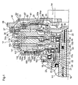
Figure 1 is a longitudinal section through a first embodiment according to the present invention of a motor-vehicle transmission provided with a gearbox with two coaxial input shafts and two clutches, -
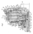
Figure 2 is a longitudinal section through a second embodiment according to the present invention of a motor-vehicle transmission of the type shown inFigure 1 , -
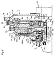
Figure 3 is a longitudinal section through a third embodiment according to the present invention of a motor-vehicle transmission provided with a gearbox with one input shaft and one clutch, and -
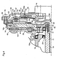
Figure 4 is a longitudinal section through a fourth embodiment according to the present invention of a motor-vehicle transmission of the type shown inFigure 3 . - In the description and the claims which follow, terms such as "longitudinal" or "axial", as well as "radial" or "transverse" are intended to refer to the mounted condition on a motor vehicle.
- With reference to
Figure 1 , a motor-vehicle transmission, advantageously (but not necessarily) of the power-shift type, comprises: - a gearbox, which is not shown since it is known (for example, from Italian patent application T02001A000286) with two coaxial input shafts, that is, an
inner input shaft 11 and anouter input shaft 111, respectively, and - a
clutch unit 12 as a coupling unit with twoclutches crankshaft 14 of the internal combustion engine, of which only the end portion facing towards the transmission is shown, for rotation with thegearbox input shafts - The gearbox is enclosed by a
support housing 16, shown partially inFigure 1 and having, at the end facing towards theclutch unit 12, atubular extension 17 with a centralaxial hole 17a through which the twocoaxial input shafts outer shaft 111 has a tubular structure with a substantially cylindrical, central,coaxial cavity 15. Thecavity 15 houses theinner shaft 11 which is supported for rotation by support elements of known type, including, for example, a needle bearing 18. Theinner shaft 11 also has a tubular structure with a substantially cylindrical, central,coaxial cavity 19 in which arod 20 for actuating theclutch 13 is slidable axially. - A
sleeve 21 is interposed radially between theouter input shaft 111 and thecylindrical hole 17a formed in theextension 17 of thesupport housing 16. At the end facing towards theclutch unit 12, thesleeve 21 forms acylindrical portion 22 which is coaxial with the two input shafts and which defines, with thecylindrical hole 17a, an outerannular space 23 and, with theshaft 111, an innerannular space 24. - Two oil-
seal rings sleeve 21 and theouter input shaft 111 and between the twoinput shafts clutch unit 12 which, on the other hand, operates dry. - A two-mass flywheel, generally indicated 30 and comprising a
first mass 31 and asecond mass 32, is interposed axially between theclutch unit 12 and thecrankshaft 14. - The
first mass 31 of theflywheel 30 comprises afirst element 33 and asecond element 34 which are arranged side by side, the first facing towards the engine and the second towards the gearbox. - The
first element 33 of thefirst mass 31 is formed as a disc with an axial section that is variously shaped but extends substantially radially. A plurality of holes are formed in a radially inner position of thefirst element 33 for the fixing of the element to thecrankshaft 14 by means ofscrews 35 and, in a radially outer position, atubular extension 37 provided with aninternal ring gear 36 projects axially towards thesecond element 34. Thefirst element 33 also has, on its outer periphery, aring gear 39 for meshing with a pinion of the electric starter (not shown) for starting the internal combustion engine of the vehicle. - The
second element 34 of thefirst mass 31 also is formed as a disc having a substantially L-shaped axial section with a cylindricalannular portion 34a which projects axially towards thefirst element 33. Aring gear 38 is formed on the outer periphery of theportion 34a and meshes permanently with thering gear 36 of thefirst element 33 so as to connect the twoelements first mass 31 for rotation. Thesecond element 34 is also connected to thesecond mass 32 through atorsional damper 40, such as for example flexible-coupling springs. - The
second mass 32 of theflywheel 30 also comprises afirst element 41 and asecond element 141, both of which are disc-shaped and which are disposed on axially opposite sides of thesecond element 34 of thefirst mass 31 and are fixed together by means ofscrews 43. Thesecond mass 32 is supported for rotation by a radial ball bearing 44 mounted on the outergearbox input shaft 111. The outer race of thebearing 44 is clamped axially between a pair of shoulders provided by the twoelements second mass 32. The inner race of thebearing 44 is mounted in axial abutment on one side with a side of asplined portion 45 formed on the outer cylindrical surface of theshaft 111, and is clamped axially on the opposite side by means of aring nut 46. - The
first element 41 of thesecond mass 32 of theflywheel 30 is also arranged to act as an abutment member for theclutch 13 associated with the innergearbox input shaft 11. - The
clutch 13 is composed of a driven portion and of a driving portion which are fast for rotation with theinput shaft 11 and with the crankshaft 14 (via the flywheel 30), respectively, and which can be coupled torsionally with each other to permit the transmission of torque between theshafts - The driven portion of the
clutch 13 comprises aplate 48 which is provided with rings made of friction material on both of its axial faces and which is fixed, by means ofrivets 49, to aflange 50a of ahub 50 arranged so as to be slidable axially along asplined end portion 51 of the innergearbox input shaft 11. - In addition to the above-described
first element 41, the driving portion of theclutch 13 comprises acover 52 fixed to the periphery of thefirst element 41 by means ofscrews 53 and having a substantiallyvertical wall 52a which extends radially inwards on the axially opposite side of theplate 48 to thefirst element 41. An axially movableclutch pressure plate 54 interposed between theplate 48 and thecover 52 is restrained for rotation with the latter by means oftangential tabs 57. Theclutch pressure plate 54 is urged axially against theplate 48 by adisc spring 55 so that theplate 48 is kept clamped between thefirst element 41 and thepressure plate 54 and can therefore transmit torque with these two components as a result of the friction between the axial abutment surfaces. - The
disc spring 55 is clamped axially between its two radially outer and radially inner end portions, respectively, by thevertical wall 52a of thecover 52 and by a disc-shaped engagement element 56 which can be moved axially by the actuatingrod 20. When the spring is not deformed, that is, when no command is imparted to theclutch 13 by means of therod 20, a radially intermediate portion of thespring 55 exerts a leftward axial pressure (as observed inFigure 1 ) against aprojection 54a of theclutch pressure plate 54, thus keeping theclutch 13 engaged. - In order to disengage the
clutch 13 it is necessary to move the actuatingrod 20 towards the right along thecavity 19 of theinner input shaft 11 so as to urge the radially inner portion of thespring 55 by means of theengagement element 56. Thespring 55 pivots on thecover 52 and thus tends to rotate about its radially outer edge until it achieves the deformed configuration shown in broken line inFigure 1 . In this condition, theclutch pressure plate 54, which is no longer subject to the axial pressure of thespring 55, moves away from theplate 48 by virtue of the action of thetangential tabs 57, thus interrupting the transmission of torque between the driving portion and the driven portion of the clutch. - The structure of the
clutch 113 associated with the outergearbox input shaft 111 will now be described, again with reference toFigure 1 , in which the components and parts of theclutch 113 which correspond in structure and/or function to those of theclutch 13 are indicated by the same reference numerals but increased by 100. - The
clutch 113 is composed of a driven portion and of a driving portion which are fast for rotation with theouter input shaft 111 and with the crankshaft 14 (via the flywheel 30), respectively, and which can be coupled torsionally with each other to permit the transmission of torque between theshafts - The driven portion of the
clutch 113 comprises aplate 148 which is provided with rings made of friction material on both of its axial faces and which is fixed by means ofrivets 149 to aflange 150a of ahub 150 arranged so as to be slidable axially along asplined portion 151 of the outergearbox input shaft 111. - The driving portion of the
clutch 113 comprises, substantially: - an abutment member provided by the
second element 141 of thesecond mass 32 of theflywheel 30, - a
cover 152 fixed byscrews 153 to the periphery of thesecond element 141 and having a substantiallyvertical wall 152a which extends radially inwards on the axially opposite side of theplate 148 to thesecond element 141, separating theclutch unit 12 from the gearbox, and - an axially movable
clutch pressure plate 154 interposed between theplate 148 and thecover 152 and restrained for rotation with the latter by means of tangential tabs (not visible inFigure 1 ). - The
cover 152 is supported for rotation by a radial ball bearing 60 fitted on thetubular extension 17 of thegearbox housing 16. The outer race of thebearing 60 is free axially, whereas the inner race is clamped by a snap ring 61 against a shoulder formed in thehousing 16. - In rest conditions, that is, when the driver of the vehicle is not imparting any commands to the clutch, the
plate 148 is kept clamped between thesecond element 141 and theclutch pressure plate 154 as a result of the axial pressure exerted by adisc spring 155 on theplate 154. - The
disc spring 155 is restrained on thevertical wall 152a of thecover 152 and bears, with its two radially outer and radially inner end portions, respectively, against aprojection 154a of theclutch pressure plate 154, and against anannular engagement element 145. Theelement 145 is supported for rotation by aradial ball bearing 62 mounted on an end of aplunger 63. - The
plunger 63 is arranged so as to be slidable axially in theannular space 23 formed between thecylindrical portion 22 of thesleeve 21 and thetubular extension 17 of thegearbox support housing 16. The supply of oil under pressure to theannular space 23 from a duct formed in avertical wall 16a of thegearbox housing 16 brings about rightward axial movement of theplunger 63 as far as a travel-limit position defined by asnap ring 64 fitted on the end of thesleeve 22 facing the engine. By means of theengagement element 145, theplunger 63 pulls along the radially inner end portion of thespring 155 which thus tends to pivot about its radially intermediate portion, which is restrained on thecover 152, until it achieves the deformed configuration shown in broken outline inFigure 1 . In this condition, theclutch pressure plate 154, which is no longer subject to the axial pressure of thespring 155, moves away from theplate 148 by virtue of the action of the tangential tabs, thus interrupting the transmission of torque between the driving portion and the driven portion of the clutch 113. - A second embodiment according to the present invention of a motor-vehicle transmission provided with a gearbox with two coaxial input shafts and two clutches is shown in
Figure 2 in which parts and elements identical or corresponding to those ofFigure 1 have been given the same reference numerals. - As is clear from a comparison between
Figures 1 and2 , this second embodiment is substantially identical to that described above, with the difference that the first andsecond elements first mass 31 of theflywheel 30 are connected for rotation with one another by means ofscrews 58 instead of by meshing between respective ring gears 36 and 38. -
Figures 3 and4 show two preferred embodiments according to the present invention of a motor-vehicle transmission provided with a gearbox having only one input shaft and only one clutch. These embodiments will not be described in further detail since they are clearly based on the two embodiments described above. - In particular, the embodiment shown in
Figure 3 is derived from the part of the transmission ofFigure 1 that comprises the clutch 113 associated with the outergearbox input shaft 111. For this reason, all of the components forming part of the clutch of the transmission ofFigure 3 are indicated by the same reference numerals as those used for the corresponding components of, the clutch 113 of the transmission ofFigure 1 . The same applies to the embodiment ofFigure 4 which is based on the structure of the clutch 13 of the transmission ofFigure 2 . - In comparison with the third embodiment, the fourth embodiment has the advantage of being more compact axially by virtue of the sliding-rod clutch-actuating mechanism.
Claims (18)
- A motor-vehicle transmission comprising:a gearbox having at least one input shaft (11, 111; 111; 11) and a support housing (16),a coupling unit (12) interposed between the gearbox and a crankshaft (14) of the motor-vehicle and having at least one dry clutch (13, 113; 113; 13) operable to connect the crankshaft (14) for rotation with the at least one input shaft (11, 111; 111; 11), wherein the at least one dry clutch (13, 113; 113; 13) includes a driven portion (48, 50, 148, 150; 148, 150; 48, 50) connected for rotation with the at least one input shaft (11, 111; 111; 11) and a driving portion (41, 52, 54, 141, 152, 154; 141, 152, 154; 41, 52, 54) connected for rotation with the crankshaft (14), androtation support means (44, 60) for supporting the driving portion (41, 52, 54, 141, 152, 154; 141, 152, 154; 41, 52, 54) of the at least one dry clutch (13, 113; 113; 13) for rotation,wherein said rotation support means (44,60) include a first bearing (44) having an inner race mounted on the at least one input shaft (111; 111; 11),
characterized in that the inner race of the first bearing (44) is in axial abutment on one side and is clamped axially on the opposite side, whereby clutch-actuating forces are not discharged onto the crankshaft (14), and in that said rotation support means (44,60) further include a second bearing (60) mounted on the support housing (16). - A transmission according to Claim 1, wherein the first bearing (44) is a radial ball bearing.
- A transmission according to Claim 1 or Claim 2, wherein the gearbox has two coaxial input shafts (11, 111), namely an inner shaft (11) and an outer hollow shaft (111), wherein the coupling unit (12) has first and second dry clutches (13, 113) operable to connect the crankshaft (14) for rotation with the inner input shaft (11) and the outer input shaft (111), respectively, and wherein the first bearing (44) is arranged between the driving portions (41, 52, 54, 141, 152, 154) of the two clutches (13, 113) and the outer input shaft (111) and is configured to support said driving portions for rotation about said input shaft.
- A transmission according to Claim 3, wherein the driving portions (41, 52, 54, 141, 152, 154) of the first and second dry clutches (13, 113) comprise each a respective abutment member (41, 141) intended to be connected for rotation with the crankshaft (14), wherein the driven portions (48, 50, 148, 150) of the first and second dry clutches (13, 113) comprise each a respective friction plate (48, 148) which is connected for rotation with a respective input shaft (11, 111) and is configured to be clamped against the respective abutment member (41, 141), and wherein both the abutment members (41, 141) are supported for rotation by the first bearing (44).
- A transmission according to Claim 4, wherein the first and second clutches (13, 113) further comprise each a respective resilient element (55, 155) configured to keep the associated clutch (13, 113) in a normally engaged or disengaged condition and a cover member (52, 152) coupled for rotation with the respective abutment member (41, 141) and arranged to provide a restraint for the respective resilient element (55, 155).
- A transmission according to Claim 5, wherein the cover member (152) of the second clutch (113) is supported for rotation by the second bearing (60).
- A transmission according to any of Claims 3 to 6, further comprising an actuating rod (20) which is slidably arranged in a coaxial cavity (19) provided in the inner input shaft (11) and is operable to actuate the first clutch (13).
- A transmission according to any of Claims 3 to 7, further comprising an annular plunger (63) which is arranged around the outer input shaft (111) so as to be axially slidable thereon and is operable to actuate the second clutch (113).
- A transmission according to any of Claims 3 to 8, further comprising a two-mass flywheel (30) intended to be interposed between the coupling unit (12) and the crankshaft (14), wherein the two-mass flywheel (30) comprises a first engine-side mass (31) and a second gearbox-side mass (32), and wherein the abutment members (41, 141) of the first and second clutches (13, 113) form at least part of the second mass (32).
- A transmission according to any of Claims 3 to 9, wherein the first and second clutches (13, 113) are normally-engaged.
- A transmission according to Claim 1 or Claim 2, wherein the gearbox has one input shaft (111; 11), wherein the coupling unit (12) has one dry clutch (113; 13) operable to connect the crankshaft (14) for rotation with the input shaft (111; 11), and wherein the first bearing (44) is arranged between the driving portion (141, 152, 154; 41, 52, 54) of the clutch (113, 13) and the input shaft (111; 11) and is configured to support said driving portion for rotation about said input shaft.
- A transmission according to Claim 11, wherein the driving portion (141, 152, 154; 41, 52, 54) of the clutch (113; 13) comprises an abutment member (141; 41) intended to be connected for rotation with the crankshaft (14), wherein the driven portion (148, 150; 48, 50) of the clutch (113; 13) comprises a friction plate (148; 48) which is connected for rotation with the input shaft (111; 11) and is configured to be clamped against the abutment member (141; 41), and wherein the abutment member (141; 41) is supported for rotation by the first bearing (44).
- A transmission according to Claim 12, wherein the clutch (113; 13) further comprises a resilient element (155; 55) configured to keep the clutch (113; 13) in a normally engaged or disengaged condition and a cover member (152; 52) coupled for rotation with the abutment member (141; 41) and arranged to provide a restraint for the resilient element (155; 55).
- A transmission according to Claim 13, wherein the cover member (152) of the clutch (113) is supported for rotation by the second bearing (60).
- A transmission according to any of Claims 11 to 13, further comprising an actuating rod (20) which is slidably arranged in a coaxial cavity (19) provided in the input shaft (11) and is operable to actuate the clutch (13).
- A transmission according to any of Claims 11 to 14, further comprising an annular plunger (63) which is arranged around the input shaft (111) so as to be axially slidable thereon and is operable to actuate the clutch (113).
- A transmission according to any of Claims 12 to 16, further comprising a two-mass flywheel (30) intended to be interposed between the coupling unit (12) and the crankshaft (14), wherein the two-mass flywheel (30) comprises a first engine-side mass (31) and a second gearbox-side mass (32), and wherein the abutment member (141; 41) of the clutch (113; 13) forms at least part of the second mass (32).
- A transmission according to Claim 9 or Claim 17, wherein the first mass (31) of the flywheel (30) comprises a first element (33) intended to be fixed directly to the crankshaft (14) and a second element (34) connected for rotation with the second mass (32) by means of a torsional damper (40), and wherein said first and second elements (33, 34) are torsionally coupled to one another by means of a toothed connection (36, 38).
Priority Applications (5)
| Application Number | Priority Date | Filing Date | Title |
|---|---|---|---|
| EP05112661A EP1650455B1 (en) | 2002-05-08 | 2003-05-07 | A motor-vehicle double-clutch transmission |
| EP10182459.7A EP2400182B1 (en) | 2002-05-08 | 2003-05-07 | A motor-vehicle transmission having a gearbox and a clutch and flywheel assembly |
| EP06110630A EP1662162A1 (en) | 2002-05-08 | 2003-05-07 | A clutch and flywheel assembly for a motor-vehicle |
| EP05112668A EP1653105B1 (en) | 2002-05-08 | 2003-05-07 | A two-mass flywheel for a motor-vehicle |
| EP10161890.8A EP2221509B1 (en) | 2002-05-08 | 2003-05-07 | A motor-vehicle transmission |
Applications Claiming Priority (2)
| Application Number | Priority Date | Filing Date | Title |
|---|---|---|---|
| IT2002TO000382A ITTO20020382A1 (en) | 2002-05-08 | 2002-05-08 | AUTOMOTIVE TRANSMISSION. |
| ITTO20020382 | 2002-05-08 |
Related Child Applications (9)
| Application Number | Title | Priority Date | Filing Date |
|---|---|---|---|
| EP05112668A Division EP1653105B1 (en) | 2002-05-08 | 2003-05-07 | A two-mass flywheel for a motor-vehicle |
| EP10161890.8A Division EP2221509B1 (en) | 2002-05-08 | 2003-05-07 | A motor-vehicle transmission |
| EP06110630A Division EP1662162A1 (en) | 2002-05-08 | 2003-05-07 | A clutch and flywheel assembly for a motor-vehicle |
| EP05112661A Division EP1650455B1 (en) | 2002-05-08 | 2003-05-07 | A motor-vehicle double-clutch transmission |
| EP10182459.7A Division EP2400182B1 (en) | 2002-05-08 | 2003-05-07 | A motor-vehicle transmission having a gearbox and a clutch and flywheel assembly |
| EP05112661.3 Division-Into | 2005-12-21 | ||
| EP05112668.8 Division-Into | 2005-12-21 | ||
| EP06110630.8 Division-Into | 2006-03-03 | ||
| EP09172238.9 Division-Into | 2009-10-05 |
Publications (3)
| Publication Number | Publication Date |
|---|---|
| EP1361102A2 EP1361102A2 (en) | 2003-11-12 |
| EP1361102A3 EP1361102A3 (en) | 2005-07-20 |
| EP1361102B1 true EP1361102B1 (en) | 2010-05-05 |
Family
ID=27639055
Family Applications (6)
| Application Number | Title | Priority Date | Filing Date |
|---|---|---|---|
| EP06110630A Ceased EP1662162A1 (en) | 2002-05-08 | 2003-05-07 | A clutch and flywheel assembly for a motor-vehicle |
| EP10161890.8A Expired - Lifetime EP2221509B1 (en) | 2002-05-08 | 2003-05-07 | A motor-vehicle transmission |
| EP05112668A Expired - Lifetime EP1653105B1 (en) | 2002-05-08 | 2003-05-07 | A two-mass flywheel for a motor-vehicle |
| EP10182459.7A Expired - Lifetime EP2400182B1 (en) | 2002-05-08 | 2003-05-07 | A motor-vehicle transmission having a gearbox and a clutch and flywheel assembly |
| EP03010242A Expired - Lifetime EP1361102B1 (en) | 2002-05-08 | 2003-05-07 | Support for a coupling unit in a motor-vehicle transmission |
| EP05112661A Expired - Lifetime EP1650455B1 (en) | 2002-05-08 | 2003-05-07 | A motor-vehicle double-clutch transmission |
Family Applications Before (4)
| Application Number | Title | Priority Date | Filing Date |
|---|---|---|---|
| EP06110630A Ceased EP1662162A1 (en) | 2002-05-08 | 2003-05-07 | A clutch and flywheel assembly for a motor-vehicle |
| EP10161890.8A Expired - Lifetime EP2221509B1 (en) | 2002-05-08 | 2003-05-07 | A motor-vehicle transmission |
| EP05112668A Expired - Lifetime EP1653105B1 (en) | 2002-05-08 | 2003-05-07 | A two-mass flywheel for a motor-vehicle |
| EP10182459.7A Expired - Lifetime EP2400182B1 (en) | 2002-05-08 | 2003-05-07 | A motor-vehicle transmission having a gearbox and a clutch and flywheel assembly |
Family Applications After (1)
| Application Number | Title | Priority Date | Filing Date |
|---|---|---|---|
| EP05112661A Expired - Lifetime EP1650455B1 (en) | 2002-05-08 | 2003-05-07 | A motor-vehicle double-clutch transmission |
Country Status (4)
| Country | Link |
|---|---|
| EP (6) | EP1662162A1 (en) |
| AT (3) | ATE422227T1 (en) |
| DE (3) | DE60332412D1 (en) |
| IT (1) | ITTO20020382A1 (en) |
Cited By (1)
| Publication number | Priority date | Publication date | Assignee | Title |
|---|---|---|---|---|
| DE102010022237A1 (en) * | 2010-05-20 | 2011-11-24 | Schaeffler Technologies Gmbh & Co. Kg | Dual coupling for coupling motor-sided input shaft with gear-sided output shafts in gear train of motor car, has coupling cover connected with central counter plate and mounted on actuation device by axial immovable axial bearing |
Families Citing this family (21)
| Publication number | Priority date | Publication date | Assignee | Title |
|---|---|---|---|---|
| US7063195B2 (en) * | 2004-07-27 | 2006-06-20 | Ford Global Technologies, Llc | Dual clutch assembly for a motor vehicle powertrain |
| ATE415572T1 (en) | 2004-09-03 | 2008-12-15 | Luk Lamellen & Kupplungsbau | TORQUE TRANSMISSION DEVICE |
| FR2880095B1 (en) * | 2004-12-29 | 2008-07-04 | Renault Sas | GEARBOX WHERE THE GEAR LUBRICATION OIL IS INSULATED FROM THE CLUTCHES |
| DE102006062833C5 (en) * | 2005-06-09 | 2018-06-14 | Schaeffler Technologies AG & Co. KG | Torque transfer device |
| FR2886996B1 (en) | 2005-06-14 | 2007-08-17 | Valeo Embrayages | MECHANISM OF MULTIPLE CLUTCHES WITH FRICTION DISC IN 2 PARTS |
| FR2886998B1 (en) * | 2005-06-14 | 2007-08-24 | Valeo Embrayages | MULTIPLE CLUTCH MECHANISM WITH LARGE DEBATMENT THRUST |
| FR2895476B1 (en) | 2005-12-22 | 2009-06-05 | Valeo Embrayages | MULTIPLE CLUTCH ASSEMBLY, IN PARTICULAR OF A MOTOR VEHICLE |
| FR2896287B1 (en) * | 2006-01-18 | 2009-08-21 | Pascal Thery | DOUBLE CLUTCH FOR AUTOMOTIVE TRANSMISSION |
| DE102006024275A1 (en) * | 2006-05-24 | 2007-11-29 | Zf Friedrichshafen Ag | friction clutch |
| DE102006025529A1 (en) † | 2006-06-01 | 2007-12-06 | Zf Friedrichshafen Ag | Torque transmission arrangement for the drive train of a vehicle |
| DE502008001059D1 (en) * | 2007-04-25 | 2010-09-16 | Luk Lamellen & Kupplungsbau | Double coupling |
| FR2929359B1 (en) * | 2008-03-25 | 2010-06-04 | Valeo Embrayages | FRICTION CLUTCH DEVICE COMPRISING A DOUBLE DAMPING WHEEL WITH A SECONDARY ASSEMBLY FITTED AXIALLY IN RELATION TO A REACTION TRAY |
| US8057310B2 (en) * | 2008-09-26 | 2011-11-15 | GM Global Technology Operations LLC | Integrated damper and starter ring gear for a hybrid vehicle |
| DE112011101033B4 (en) * | 2010-03-25 | 2023-11-09 | Schaeffler Technologies AG & Co. KG | Double coupling |
| DE112011101031B4 (en) | 2010-03-25 | 2021-10-28 | Schaeffler Technologies AG & Co. KG | Double coupling |
| DE112011101567A5 (en) * | 2010-05-06 | 2013-02-07 | Schaeffler Technologies AG & Co. KG | Double coupling |
| DE102011115227B4 (en) | 2010-10-08 | 2024-04-04 | Borgwarner Inc. | Dual clutch device |
| WO2013079045A1 (en) | 2011-11-30 | 2013-06-06 | Schaeffler Technologies AG & Co. KG | Assembly of a small dual clutch |
| DE102016202540B3 (en) * | 2016-02-18 | 2017-07-06 | Continental Automotive Gmbh | Vehicle driveline with clutch assembly and vibration damper |
| DE102018104361A1 (en) * | 2018-02-27 | 2019-08-29 | Schaeffler Technologies AG & Co. KG | Coupling arrangement with additional support bearing; as well as drive unit |
| KR102362359B1 (en) * | 2020-07-16 | 2022-02-11 | 현대트랜시스 주식회사 | Torsional damper assembly |
Citations (3)
| Publication number | Priority date | Publication date | Assignee | Title |
|---|---|---|---|---|
| US3185274A (en) * | 1961-07-01 | 1965-05-25 | Ferodo Sa | Clutch device with multiple outputs |
| DE3037990A1 (en) * | 1980-10-08 | 1982-05-13 | Volkswagenwerk Ag, 3180 Wolfsburg | Car gear transmission has coaxial input shafts - alternately couplable to engine and to gears by stepwise actuation of gate with cam slots |
| DE10034730A1 (en) * | 1999-09-30 | 2001-08-09 | Mannesmann Sachs Ag | Multiple coupling device, possibly in combination with a torsional vibration damper arrangement and / or an electric machine |
Family Cites Families (8)
| Publication number | Priority date | Publication date | Assignee | Title |
|---|---|---|---|---|
| DE3941250C2 (en) * | 1988-12-24 | 1999-09-16 | Luk Lamellen & Kupplungsbau | Device for damping vibrations |
| DE4323601A1 (en) * | 1993-07-09 | 1995-01-12 | Mannesmann Ag | Drive arrangement for a hybrid vehicle |
| ES2122821B1 (en) * | 1993-12-22 | 1999-07-01 | Fichtel & Sachs Ag | HYDRODYNAMIC TURN TORQUE CONVERTER WITH BRIDGE CLUTCH. |
| KR100647408B1 (en) * | 1998-04-06 | 2006-11-17 | 루크 라멜렌 운트 쿠플룽스바우베타일리궁스 카게 | Detachable Flywheel |
| EP1067312B1 (en) * | 1999-07-05 | 2001-12-12 | Ford Global Technologies, Inc., A subsidiary of Ford Motor Company | Six speed transmission for motor vehicles |
| DE10004189C5 (en) * | 1999-09-30 | 2015-05-21 | Volkswagen Ag | Multiple clutch device |
| FR2803346B1 (en) * | 1999-12-30 | 2002-04-26 | Valeo | DOUBLE CLUTCH, ESPECIALLY FOR A MOTOR VEHICLE |
| DE10134118B4 (en) * | 2001-07-13 | 2013-02-21 | Volkswagen Ag | Double coupling |
-
2002
- 2002-05-08 IT IT2002TO000382A patent/ITTO20020382A1/en unknown
-
2003
- 2003-05-07 EP EP06110630A patent/EP1662162A1/en not_active Ceased
- 2003-05-07 AT AT05112661T patent/ATE422227T1/en not_active IP Right Cessation
- 2003-05-07 EP EP10161890.8A patent/EP2221509B1/en not_active Expired - Lifetime
- 2003-05-07 EP EP05112668A patent/EP1653105B1/en not_active Expired - Lifetime
- 2003-05-07 EP EP10182459.7A patent/EP2400182B1/en not_active Expired - Lifetime
- 2003-05-07 EP EP03010242A patent/EP1361102B1/en not_active Expired - Lifetime
- 2003-05-07 AT AT03010242T patent/ATE467072T1/en not_active IP Right Cessation
- 2003-05-07 AT AT05112668T patent/ATE462892T1/en not_active IP Right Cessation
- 2003-05-07 EP EP05112661A patent/EP1650455B1/en not_active Expired - Lifetime
- 2003-05-07 DE DE60332412T patent/DE60332412D1/en not_active Expired - Lifetime
- 2003-05-07 DE DE60331964T patent/DE60331964D1/en not_active Expired - Lifetime
- 2003-05-07 DE DE60326091T patent/DE60326091D1/en not_active Expired - Lifetime
Patent Citations (3)
| Publication number | Priority date | Publication date | Assignee | Title |
|---|---|---|---|---|
| US3185274A (en) * | 1961-07-01 | 1965-05-25 | Ferodo Sa | Clutch device with multiple outputs |
| DE3037990A1 (en) * | 1980-10-08 | 1982-05-13 | Volkswagenwerk Ag, 3180 Wolfsburg | Car gear transmission has coaxial input shafts - alternately couplable to engine and to gears by stepwise actuation of gate with cam slots |
| DE10034730A1 (en) * | 1999-09-30 | 2001-08-09 | Mannesmann Sachs Ag | Multiple coupling device, possibly in combination with a torsional vibration damper arrangement and / or an electric machine |
Cited By (1)
| Publication number | Priority date | Publication date | Assignee | Title |
|---|---|---|---|---|
| DE102010022237A1 (en) * | 2010-05-20 | 2011-11-24 | Schaeffler Technologies Gmbh & Co. Kg | Dual coupling for coupling motor-sided input shaft with gear-sided output shafts in gear train of motor car, has coupling cover connected with central counter plate and mounted on actuation device by axial immovable axial bearing |
Also Published As
| Publication number | Publication date |
|---|---|
| ITTO20020382A1 (en) | 2003-11-10 |
| DE60331964D1 (en) | 2010-05-12 |
| EP1361102A3 (en) | 2005-07-20 |
| EP1361102A2 (en) | 2003-11-12 |
| EP1650455A1 (en) | 2006-04-26 |
| EP2400182B1 (en) | 2019-07-24 |
| EP2221509A2 (en) | 2010-08-25 |
| EP1653105A1 (en) | 2006-05-03 |
| EP1653105B1 (en) | 2010-03-31 |
| ATE462892T1 (en) | 2010-04-15 |
| EP2400182A1 (en) | 2011-12-28 |
| ATE467072T1 (en) | 2010-05-15 |
| DE60326091D1 (en) | 2009-03-19 |
| ITTO20020382A0 (en) | 2002-05-08 |
| ATE422227T1 (en) | 2009-02-15 |
| EP1662162A1 (en) | 2006-05-31 |
| EP2221509B1 (en) | 2015-10-21 |
| EP1650455B1 (en) | 2009-02-04 |
| EP2221509A3 (en) | 2011-06-01 |
| DE60332412D1 (en) | 2010-06-17 |
Similar Documents
| Publication | Publication Date | Title |
|---|---|---|
| EP1650455B1 (en) | A motor-vehicle double-clutch transmission | |
| US6634477B2 (en) | Clutch assembly | |
| US7063195B2 (en) | Dual clutch assembly for a motor vehicle powertrain | |
| US6840364B2 (en) | Power train for use in motor vehicles and the like | |
| JP7044549B2 (en) | Clutch with a thin metal plate structure with at least two clutch discs | |
| US8448770B2 (en) | Multiplate clutch | |
| US5168971A (en) | Transmission clutch for a motor vehicle having a dynamic absorber | |
| CN102713327A (en) | Torque transmission device | |
| US5135089A (en) | Transmission clutch for a motor vehicle having a dynamic absorber | |
| KR20060050952A (en) | Torque transmission device | |
| WO2012048211A2 (en) | Dual clutch device | |
| JPH026924B2 (en) | ||
| GB2153929A (en) | Friction clutch with auxiliary flywheel | |
| US8662273B2 (en) | Dual clutch | |
| CN109661525B (en) | Clutch mechanism and transmission system comprising such a clutch mechanism | |
| US5366054A (en) | Friction clutch cover assemblies | |
| US20080006502A1 (en) | Clutch arrangement for the drive train of a vehicle | |
| JP2002098165A (en) | Starting clutch | |
| GB2125120A (en) | Friction clutch apparatus | |
| EP1002200A1 (en) | Clutch assembly | |
| EP1830095B1 (en) | Double clutch transmission for a motor vehicle | |
| US4889218A (en) | Torsion-damping flywheel | |
| US20070034476A1 (en) | Clutch assembly | |
| EP2141376B1 (en) | Clutch driven plates | |
| US6997298B2 (en) | Dual clutch assembly for a motor vehicle powertrain |
Legal Events
| Date | Code | Title | Description |
|---|---|---|---|
| PUAI | Public reference made under article 153(3) epc to a published international application that has entered the european phase |
Free format text: ORIGINAL CODE: 0009012 |
|
| AK | Designated contracting states |
Kind code of ref document: A2 Designated state(s): AT BE BG CH CY CZ DE DK EE ES FI FR GB GR HU IE IT LI LU MC NL PT RO SE SI SK TR |
|
| AX | Request for extension of the european patent |
Extension state: AL LT LV MK |
|
| RIN1 | Information on inventor provided before grant (corrected) |
Inventor name: CAENAZZO, DARIO Inventor name: MESITI, DOMENICO Inventor name: UBERTI, MAURIZIO Inventor name: PREGNOLATO, GIANLUIGI |
|
| PUAL | Search report despatched |
Free format text: ORIGINAL CODE: 0009013 |
|
| AK | Designated contracting states |
Kind code of ref document: A3 Designated state(s): AT BE BG CH CY CZ DE DK EE ES FI FR GB GR HU IE IT LI LU MC NL PT RO SE SI SK TR |
|
| AX | Request for extension of the european patent |
Extension state: AL LT LV MK |
|
| RIC1 | Information provided on ipc code assigned before grant |
Ipc: 7F 16D 21/06 B Ipc: 7F 16H 57/02 A |
|
| 17P | Request for examination filed |
Effective date: 20060117 |
|
| AKX | Designation fees paid |
Designated state(s): AT BE BG CH CY CZ DE DK EE ES FI FR GB GR HU IE IT LI LU MC NL PT RO SE SI SK TR |
|
| GRAP | Despatch of communication of intention to grant a patent |
Free format text: ORIGINAL CODE: EPIDOSNIGR1 |
|
| GRAS | Grant fee paid |
Free format text: ORIGINAL CODE: EPIDOSNIGR3 |
|
| GRAA | (expected) grant |
Free format text: ORIGINAL CODE: 0009210 |
|
| AK | Designated contracting states |
Kind code of ref document: B1 Designated state(s): AT BE BG CH CY CZ DE DK EE ES FI FR GB GR HU IE IT LI LU MC NL PT RO SE SI SK TR |
|
| REG | Reference to a national code |
Ref country code: GB Ref legal event code: FG4D |
|
| REG | Reference to a national code |
Ref country code: CH Ref legal event code: EP |
|
| REG | Reference to a national code |
Ref country code: IE Ref legal event code: FG4D |
|
| REF | Corresponds to: |
Ref document number: 60332412 Country of ref document: DE Date of ref document: 20100617 Kind code of ref document: P |
|
| REG | Reference to a national code |
Ref country code: SK Ref legal event code: T3 Ref document number: E 7260 Country of ref document: SK |
|
| REG | Reference to a national code |
Ref country code: NL Ref legal event code: VDEP Effective date: 20100505 |
|
| PG25 | Lapsed in a contracting state [announced via postgrant information from national office to epo] |
Ref country code: NL Free format text: LAPSE BECAUSE OF FAILURE TO SUBMIT A TRANSLATION OF THE DESCRIPTION OR TO PAY THE FEE WITHIN THE PRESCRIBED TIME-LIMIT Effective date: 20100505 Ref country code: ES Free format text: LAPSE BECAUSE OF FAILURE TO SUBMIT A TRANSLATION OF THE DESCRIPTION OR TO PAY THE FEE WITHIN THE PRESCRIBED TIME-LIMIT Effective date: 20100816 Ref country code: SE Free format text: LAPSE BECAUSE OF FAILURE TO SUBMIT A TRANSLATION OF THE DESCRIPTION OR TO PAY THE FEE WITHIN THE PRESCRIBED TIME-LIMIT Effective date: 20100505 |
|
| PG25 | Lapsed in a contracting state [announced via postgrant information from national office to epo] |
Ref country code: AT Free format text: LAPSE BECAUSE OF FAILURE TO SUBMIT A TRANSLATION OF THE DESCRIPTION OR TO PAY THE FEE WITHIN THE PRESCRIBED TIME-LIMIT Effective date: 20100505 Ref country code: FI Free format text: LAPSE BECAUSE OF FAILURE TO SUBMIT A TRANSLATION OF THE DESCRIPTION OR TO PAY THE FEE WITHIN THE PRESCRIBED TIME-LIMIT Effective date: 20100505 Ref country code: SI Free format text: LAPSE BECAUSE OF FAILURE TO SUBMIT A TRANSLATION OF THE DESCRIPTION OR TO PAY THE FEE WITHIN THE PRESCRIBED TIME-LIMIT Effective date: 20100505 |
|
| PG25 | Lapsed in a contracting state [announced via postgrant information from national office to epo] |
Ref country code: GR Free format text: LAPSE BECAUSE OF FAILURE TO SUBMIT A TRANSLATION OF THE DESCRIPTION OR TO PAY THE FEE WITHIN THE PRESCRIBED TIME-LIMIT Effective date: 20100806 Ref country code: CY Free format text: LAPSE BECAUSE OF FAILURE TO SUBMIT A TRANSLATION OF THE DESCRIPTION OR TO PAY THE FEE WITHIN THE PRESCRIBED TIME-LIMIT Effective date: 20100505 Ref country code: MC Free format text: LAPSE BECAUSE OF NON-PAYMENT OF DUE FEES Effective date: 20100531 |
|
| REG | Reference to a national code |
Ref country code: CH Ref legal event code: PL |
|
| PG25 | Lapsed in a contracting state [announced via postgrant information from national office to epo] |
Ref country code: PT Free format text: LAPSE BECAUSE OF FAILURE TO SUBMIT A TRANSLATION OF THE DESCRIPTION OR TO PAY THE FEE WITHIN THE PRESCRIBED TIME-LIMIT Effective date: 20100906 Ref country code: EE Free format text: LAPSE BECAUSE OF FAILURE TO SUBMIT A TRANSLATION OF THE DESCRIPTION OR TO PAY THE FEE WITHIN THE PRESCRIBED TIME-LIMIT Effective date: 20100505 Ref country code: DK Free format text: LAPSE BECAUSE OF FAILURE TO SUBMIT A TRANSLATION OF THE DESCRIPTION OR TO PAY THE FEE WITHIN THE PRESCRIBED TIME-LIMIT Effective date: 20100505 |
|
| PG25 | Lapsed in a contracting state [announced via postgrant information from national office to epo] |
Ref country code: BE Free format text: LAPSE BECAUSE OF FAILURE TO SUBMIT A TRANSLATION OF THE DESCRIPTION OR TO PAY THE FEE WITHIN THE PRESCRIBED TIME-LIMIT Effective date: 20100505 Ref country code: RO Free format text: LAPSE BECAUSE OF FAILURE TO SUBMIT A TRANSLATION OF THE DESCRIPTION OR TO PAY THE FEE WITHIN THE PRESCRIBED TIME-LIMIT Effective date: 20100505 Ref country code: LI Free format text: LAPSE BECAUSE OF NON-PAYMENT OF DUE FEES Effective date: 20100531 Ref country code: CZ Free format text: LAPSE BECAUSE OF FAILURE TO SUBMIT A TRANSLATION OF THE DESCRIPTION OR TO PAY THE FEE WITHIN THE PRESCRIBED TIME-LIMIT Effective date: 20100505 Ref country code: CH Free format text: LAPSE BECAUSE OF NON-PAYMENT OF DUE FEES Effective date: 20100531 |
|
| PLBE | No opposition filed within time limit |
Free format text: ORIGINAL CODE: 0009261 |
|
| STAA | Information on the status of an ep patent application or granted ep patent |
Free format text: STATUS: NO OPPOSITION FILED WITHIN TIME LIMIT |
|
| 26N | No opposition filed |
Effective date: 20110208 |
|
| GBPC | Gb: european patent ceased through non-payment of renewal fee |
Effective date: 20100805 |
|
| PG25 | Lapsed in a contracting state [announced via postgrant information from national office to epo] |
Ref country code: IE Free format text: LAPSE BECAUSE OF NON-PAYMENT OF DUE FEES Effective date: 20100507 |
|
| REG | Reference to a national code |
Ref country code: DE Ref legal event code: R097 Ref document number: 60332412 Country of ref document: DE Effective date: 20110207 |
|
| PG25 | Lapsed in a contracting state [announced via postgrant information from national office to epo] |
Ref country code: GB Free format text: LAPSE BECAUSE OF NON-PAYMENT OF DUE FEES Effective date: 20100805 |
|
| PG25 | Lapsed in a contracting state [announced via postgrant information from national office to epo] |
Ref country code: BG Free format text: LAPSE BECAUSE OF FAILURE TO SUBMIT A TRANSLATION OF THE DESCRIPTION OR TO PAY THE FEE WITHIN THE PRESCRIBED TIME-LIMIT Effective date: 20100505 Ref country code: HU Free format text: LAPSE BECAUSE OF FAILURE TO SUBMIT A TRANSLATION OF THE DESCRIPTION OR TO PAY THE FEE WITHIN THE PRESCRIBED TIME-LIMIT Effective date: 20101106 Ref country code: LU Free format text: LAPSE BECAUSE OF NON-PAYMENT OF DUE FEES Effective date: 20100507 |
|
| PG25 | Lapsed in a contracting state [announced via postgrant information from national office to epo] |
Ref country code: TR Free format text: LAPSE BECAUSE OF FAILURE TO SUBMIT A TRANSLATION OF THE DESCRIPTION OR TO PAY THE FEE WITHIN THE PRESCRIBED TIME-LIMIT Effective date: 20100505 |
|
| PG25 | Lapsed in a contracting state [announced via postgrant information from national office to epo] |
Ref country code: BG Free format text: LAPSE BECAUSE OF FAILURE TO SUBMIT A TRANSLATION OF THE DESCRIPTION OR TO PAY THE FEE WITHIN THE PRESCRIBED TIME-LIMIT Effective date: 20100805 |
|
| REG | Reference to a national code |
Ref country code: FR Ref legal event code: PLFP Year of fee payment: 14 |
|
| REG | Reference to a national code |
Ref country code: FR Ref legal event code: PLFP Year of fee payment: 15 |
|
| REG | Reference to a national code |
Ref country code: FR Ref legal event code: PLFP Year of fee payment: 16 |
|
| PGFP | Annual fee paid to national office [announced via postgrant information from national office to epo] |
Ref country code: DE Payment date: 20200529 Year of fee payment: 18 Ref country code: FR Payment date: 20200530 Year of fee payment: 18 |
|
| PGFP | Annual fee paid to national office [announced via postgrant information from national office to epo] |
Ref country code: SK Payment date: 20200513 Year of fee payment: 18 |
|
| REG | Reference to a national code |
Ref country code: DE Ref legal event code: R119 Ref document number: 60332412 Country of ref document: DE |
|
| REG | Reference to a national code |
Ref country code: SK Ref legal event code: MM4A Ref document number: E 7260 Country of ref document: SK Effective date: 20210507 |
|
| PG25 | Lapsed in a contracting state [announced via postgrant information from national office to epo] |
Ref country code: SK Free format text: LAPSE BECAUSE OF NON-PAYMENT OF DUE FEES Effective date: 20210507 |
|
| PG25 | Lapsed in a contracting state [announced via postgrant information from national office to epo] |
Ref country code: DE Free format text: LAPSE BECAUSE OF NON-PAYMENT OF DUE FEES Effective date: 20211201 |
|
| PG25 | Lapsed in a contracting state [announced via postgrant information from national office to epo] |
Ref country code: FR Free format text: LAPSE BECAUSE OF NON-PAYMENT OF DUE FEES Effective date: 20210531 |
|
| PGFP | Annual fee paid to national office [announced via postgrant information from national office to epo] |
Ref country code: IT Payment date: 20220506 Year of fee payment: 20 |