EP1361100A2 - System and method for determining leakage in fuel vapor emission controls - Google Patents
System and method for determining leakage in fuel vapor emission controls Download PDFInfo
- Publication number
- EP1361100A2 EP1361100A2 EP03010158A EP03010158A EP1361100A2 EP 1361100 A2 EP1361100 A2 EP 1361100A2 EP 03010158 A EP03010158 A EP 03010158A EP 03010158 A EP03010158 A EP 03010158A EP 1361100 A2 EP1361100 A2 EP 1361100A2
- Authority
- EP
- European Patent Office
- Prior art keywords
- valve
- pressure
- tank
- flow
- vapor
- Prior art date
- Legal status (The legal status is an assumption and is not a legal conclusion. Google has not performed a legal analysis and makes no representation as to the accuracy of the status listed.)
- Granted
Links
Images


Classifications
-
- F—MECHANICAL ENGINEERING; LIGHTING; HEATING; WEAPONS; BLASTING
- F02—COMBUSTION ENGINES; HOT-GAS OR COMBUSTION-PRODUCT ENGINE PLANTS
- F02M—SUPPLYING COMBUSTION ENGINES IN GENERAL WITH COMBUSTIBLE MIXTURES OR CONSTITUENTS THEREOF
- F02M25/00—Engine-pertinent apparatus for adding non-fuel substances or small quantities of secondary fuel to combustion-air, main fuel or fuel-air mixture
- F02M25/08—Engine-pertinent apparatus for adding non-fuel substances or small quantities of secondary fuel to combustion-air, main fuel or fuel-air mixture adding fuel vapours drawn from engine fuel reservoir
- F02M25/0809—Judging failure of purge control system
Definitions
- the present invention relates to systems employed for controlling the emission of vapors from a vehicle fuel tank and particularly such systems as employed on light trucks and passenger cars.
- Mandated regulations for controlling vehicle on-board fuel vapor emission require that the vapor from the fuel tank vent system be stored during periods of engine in operation; and, it is thus necessary to purge the stored vapors during engine operation in order for the vapor emission control system to continue to function for its intended purpose. It is thus necessary to maintain the integrity of the components of the emission control system over the service life of the vehicle and to prevent leakage of fuel vapor from the system.
- a known system for controlling fuel tank vapor emission has included a storage device 1 connected to receive fuel vapor directly through a conduit from the fuel tank 2, with the storage device or canister 1 having an atmospheric purge inlet 3 which may be opened or closed by a control valve 4 connected to an electronic controller 5.
- the fuel tank has a tank pressure sensor 6 connected to sense the internal pressure in the tank which sensor provides an electrical input to the electronic control unit 5.
- the canister has a vapor outlet line 7 connected to provide vapor flow through a control orifice 8 with the downstream side of orifice 8 connected to the inlet of a flow control valve 9 which has its outlet connected to the combustion air inlet or intake manifold of an engine 10.
- Flow control valve 9 is an electrically operated valve controlled by the electronic control unit 5.
- An electrically operated normally open valve 11 is connected to bypass the orifice 8 and is also controlled by the electronic control unit 5.
- a differential pressure sensor 12 is connected to sense the pressure drop across the orifice 8; and, pressure sensor 12 provides an electrical input signal to the electronic controller 5.
- the controller 5 In operation, for performing leak tests, it is necessary for the controller 5 to close the atmospheric vent valve 4 and the bypass valve 11 before any leak tests can be performed.
- the flow control valve 9 is then modulated to provide a predetermined negative gauge pressure or vacuum in the tank, as sensed by the tank pressure sensor 6; and, the pressure sensed by the differential pressure sensor 12 is read.
- the flow through orifice 8 may then be determined from lookup tables and the flow rate compared with a threshold value to determine if the flow is in excess of the threshold and therefore that leakage exists.
- the present invention provides a low cost, simple and reliable system and method for performing a diagnostic leak test on a fuel tank vapor emission control system as employed in motor vehicles.
- the arrangement of the present invention provides a pressure relief valve having a bleed orifice formed therein which is disposed in the line from the vapor storage canister to the electric valve controlling flow of fuel vapor to the engine combustion air inlet,.
- a differential pressure sensor is disposed to sense the pressure drop across the pressure relief valve when closed; and, a tank pressure sensor provides tank pressure data for the test.
- An electronic controller closes the atmospheric air inlet valve to the canister, modulates the vapor flow to the engine air inlet to provide a desired tank pressure for conducting the test.
- the differential pressure sensor then provides pressure data to the controller from which flow to the bleed orifice may be determined by comparison with differential pressure values for known flows from a lookup table. The computed flow may then be compared with a threshold value to determine whether leakage exists.
- the present invention thus provides a unique and novel leak test system which eliminates the need for a separate electrically operated bypass control valve for the flow measuring orifice.
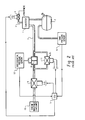
- the system of the present invention is indicated generally at 20 and has a storage device in the form of canister 22 connected to fuel tank 24 by a conduit 26, typically a flexible hose.
- the canister has an atmospheric inlet with an electrically operated shutoff valve 28, which valve is controlled along line 30 by an electronic control unit (ECU) denoted by reference numeral 32.
- ECU electronice control unit
- Canister 22 has a vapor outlet line 34 which is connected to the inlet 36 of a pressure responsive valve indicated generally at 38.
- Valve 38 has an annular valve seat 40 formed therein which communicates with the inlet 36 and which has a bleed orifice 42 formed therein.
- a moveable valve member 44 is registered against the valve seat 40 and biased thereagainst by a spring 46.
- the outlet of the valve 38 is connected via conduit 48 to the inlet of an electrically operated flow control valve 50 which has its outlet connected along line 52, which may be a flexible hose, to the combustion air inlet of an engine denoted at reference numeral 54.
- Valve 50 is connected along line 56 to receive control signals from the ECU 32.
- a pressure tap line 58 is connected to the inlet 36 of valve 38; and, the pressure tap 58 is connected to a differential pressure sensor 60 which is also connected through a pressure tap line 62 to the outlet conduit 48 of the valve 38.
- the differential pressure sensor 60 provides an electrical signal along line 64 to the ECU 32, which signal is indicative of the differential pressure measured across the valve 38 when closed and thus senses the pressure drop across bleed orifice 42.
- the moveable valve member 44 is raised from the annular valve seat 40 when a pressure differential above a certain threshold, exists across the valve 38.
- a pressure differential above a certain threshold exists across the valve 38.
- the open position of the valve member 44 is indicated in dashed outline in FIG. 1.
- a tank pressure sensor 66 is connected through a conduit 68 to the fuel tank 24; and, tank pressure sensor 66 provides an electrical signal output along line 70 to the ECU 32.
- valve 38 an alternative arrangement of the valve 38 is shown wherein the inlet 36' is connected to valve seat 40' which has a moveable valve member 44' registered thereagainst with a bleed orifice 42' formed through the valve member 44' which is biased by a spring 46'.
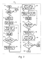
- the operational program of the ECU 32 is indicated by a block flow diagram, wherein the system upon power-up or Start at step 72 proceeds to query at step 74 as to whether the engine is running; and, if not, recycles through an appropriate Delay at step 76.
- the diagnostic system powers up and proceeds to initiate at step 78 and proceeds to step 80 where the atmospheric vent valve 28 is closed.
- the system then proceeds to modulate the flow control valve 50 at step 82 until the tank pressure read at step 84 equals zero inches H 2 O column.
- the system then proceeds to ask at step 86 whether the tank pressure is maintained at the zero inches indicated column of H 2 O; and, if not, the system returns to step 82. However, if the tank pressure is stable at zero inches indicated column of H 2 O, the system proceeds to step 88 and reads the output ⁇ P 0 of the differential pressure sensor 60.
- the system then computes the flow q 0 for ⁇ P 0 from a lookup table of flow q versus ⁇ P, which table may be made from data taken from the flow curve in FIG. 5.
- step 92 modulates the valve 50 for maintaining a tank pressure of seven inches (178 mm) indicated column of H 2 O as read at step 94.
- step 96 inquires as to whether the tank pressure is stable at seven inches (178 mm) column of H 2 O; and, if not, the system returns to step 92.
- step 98 the system proceeds to step 98 and reads the differential pressure ⁇ P 1 output of the pressure sensor 60 and proceeds to step 100 to compute the flow q 1 for ⁇ P 1 from a lookup table of values of q and ⁇ P which table may be generated by the flow data from FIG. 5.
- step 102 The system then proceeds to step 102 and asks whether the difference in flow as q 1 - q 0 is greater than a predetermined ⁇ q max; and, if the answer is affirmative, the system proceeds to provide a Leak Alarm indication at step 104. However, if the flow q 1 - q 0 is less than the predetermined threshold q max the system proceeds to indicate no leak at step 106.
- the present invention thus provides a unique and novel leak detection method and system for determining if a fuel tank vapor emission control system is leaking into the atmosphere and utilizes a pressure responsive valve to provide, when closed a bleed orifice for providing measured flow during leak testing, but permits the valve to open for normal vapor purge functions when the engine is in operation and therefore eliminates a separate electrically controlled bypass valve requiring activation before leak testing can be performed.
Abstract
Description
Claims (17)
- A method of detecting leaks in a fuel tank vapor emission control system comprising:(a) connecting a first vapor line from the tank to a vapor storage device;(b) connecting a second vapor line for allowing fuel vapor flow to an engine air inlet and disposing an electrically operated flow control valve in said second vapor line;(c) disposing a pressure relief valve in said second vapor line between said electrically operated valve and said tank and forming a flow limiting bleed orifice through said pressure relief valve and permitting limited bleed flow through the valve when closed;(d) opening the pressure relief valve when the pressure differential thereacross reaches a predetermined level;(e) modulating said electrically operated valve and sensing tank pressure and generating an electrical signal indicative thereof;(f) sensing the pressure differential across said pressure relief valve and determining flow from known values of flow verses pressure differential; and,(g) determining leakage from said tank pressure signal and said determined flow.
- The method defined in claim 1, wherein the step of disposing a pressure relief valve includes disposing a pressure relief valve includes disposing a valve having a flat plate valve member closeable against an annular valve seat and the step of forming a bleed orifice includes forming an orifice in the flat plate.
- The method defined in claim 1, wherein the step of disposing a pressure relief valve includes disposing a valve having a flat plate valve member closeable against an annular valve seat and biasing the flat plate with a spring to the closed position.
- The method defined in claim 1, wherein the step of sensing the pressure differential includes controlling said electrically operated valve in response to the tank pressure.
- The method defined in claim 1, wherein said step of sensing the pressure differential includes modulating said electrically operated valve and maintaining a predetermined tank pressure.
- The method defined in claim 1, wherein said step of connecting a first vapor line to a storage device includes connecting an electrically operated atmospheric vent valve to the storage device.
- The method defined in claim 6, wherein said step of sensing tank pressure includes closing said atmospheric vent valve.
- A method of detecting leaks in a fuel tank vapor emission control system comprising:(a) connecting a first vapor line from the tank to a vapor storage device and connecting an atmospheric vent valve to the storage device;(b) connecting a second tank vapor line to the inlet of a normally closed pressure responsive valve operable to open in response to a predetermined pressure differential thereacross and forming a bleed passage in the valve and permitting bleed flow therethrough when the valve is closed;(c) connecting the outlet of the pressure responsive valve through a flow control valve to the combustion air inlet of an engine;(d) closing said atmospheric vent valve and connecting a pressure sensor across the inlet and outlet of the pressure responsive valve and sensing the pressure differential resulting from flow through the bleed passage;(e) sensing tank pressure and providing an electrical indication thereof;(f) modulating the flow control valve to provide a predetermined tank pressure;(g) reading the sensed differential pressure at said predetermined tank pressure and determining the flow at said differential pressure; and,(h) providing an indication if said flow exceeds a certain threshold.
- The method defined in claim 8, wherein said step of connecting through a flow control valve includes connecting through an electrically operated valve.
- The method defined in claim 9, wherein said step of connecting through an electrically operated flow control valve and sensing pressure differential includes sensing with a pressure transducer and controlling the electrically operated flow control valve in response to the output of the transducer.
- The method defined in claim 9, wherein said step of connecting through an electrically operated valve includes connecting through a solenoid operated valve.
- The method defined in claim 8, wherein said step of connecting a second vapor line includes connecting to the inlet of a valve having a spring biased flat disc valving member closeable on an annular valve seat.
- The method defined in claim 13, wherein said step of forming a bleed passage includes forming an orifice in the flat disc valving member.
- A system for detecting leaks in vapor emission controls for a fuel tank comprising:(a) a storage device connected to receive fuel vapor from the tank including a closeable atmospheric vent;(b) a normally closed pressure responsive relief valve having the inlet thereof connected to receive fuel vapor from the tank, and including a bleed passage permitting bleed flow when the valve is closed;(c) a pressure sensor connected to sense the tank pressure;(d) an electrically operated flow control valve having the inlet thereof connected for receiving vapor from the outlet of said pressure responsive relief valve, and the outlet thereof connected to the combustion air inlet of an engine, wherein said electrically operated valve is controlled in response to said sensed tank pressure;(e) a differential pressure sensor connected between the inlet and the outlet of the pressure responsive relief valve;(f) circuit means operable to compute flow from output of the differential pressure sensor at a certain tank pressure with said atmospheric vent closed; and,(g) means for indicating said computed flow exceeds a certain threshold.
- The system defined in claim 14, wherein said pressure sensor includes a pressure transducer with an electrical output indicative of the sensed pressure difference.
- The system defined in claim 14, wherein said pressure responsive relief valve includes a flat disc moveable valve member.
- The system defined in claim 16, wherein said bleed passage comprises an orifice in said flat disc.
Applications Claiming Priority (2)
| Application Number | Priority Date | Filing Date | Title |
|---|---|---|---|
| US10/143,258 US6637261B1 (en) | 2002-05-10 | 2002-05-10 | System and method for determining leakage in fuel vapor emission controls |
| US143258 | 2002-05-10 |
Publications (3)
| Publication Number | Publication Date |
|---|---|
| EP1361100A2 true EP1361100A2 (en) | 2003-11-12 |
| EP1361100A3 EP1361100A3 (en) | 2006-12-06 |
| EP1361100B1 EP1361100B1 (en) | 2008-09-17 |
Family
ID=29249850
Family Applications (1)
| Application Number | Title | Priority Date | Filing Date |
|---|---|---|---|
| EP03010158A Expired - Fee Related EP1361100B1 (en) | 2002-05-10 | 2003-05-06 | System and method for determining leakage in fuel vapor emission controls |
Country Status (7)
| Country | Link |
|---|---|
| US (1) | US6637261B1 (en) |
| EP (1) | EP1361100B1 (en) |
| JP (1) | JP4318072B2 (en) |
| CA (1) | CA2427724A1 (en) |
| DE (1) | DE60323558D1 (en) |
| ES (1) | ES2314142T3 (en) |
| MX (1) | MXPA03004150A (en) |
Cited By (1)
| Publication number | Priority date | Publication date | Assignee | Title |
|---|---|---|---|---|
| EP2108808A1 (en) * | 2008-04-08 | 2009-10-14 | MAGNETI MARELLI POWERTRAIN S.p.A. | Method for diagnosting evaporative losses from a fuel tank of an internal combastion engine |
Families Citing this family (3)
| Publication number | Priority date | Publication date | Assignee | Title |
|---|---|---|---|---|
| US7107971B2 (en) * | 2004-10-15 | 2006-09-19 | Eaton Corporation | Isolation valve useful in fuel tank emission control systems |
| US10533506B2 (en) * | 2017-10-02 | 2020-01-14 | Ford Global Technologies, Llc | Systems and methods for an evaporative emissions system and fuel system having a single delta pressure sensor |
| US10138846B1 (en) * | 2017-10-02 | 2018-11-27 | Ford Global Technologies, Llc | Systems and methods for an evaporative emissions system and fuel system having a single delta pressure sensor |
Citations (3)
| Publication number | Priority date | Publication date | Assignee | Title |
|---|---|---|---|---|
| US5284050A (en) * | 1991-04-08 | 1994-02-08 | Nippondenso Co., Ltd. | Self-diagnosis apparatus in system for prevention of scattering of fuel evaporation gas |
| DE19833865A1 (en) * | 1998-07-28 | 2000-02-03 | Bosch Gmbh Robert | Device and method for testing the functionality of a tank ventilation system of an internal combustion engine |
| WO2001073283A1 (en) * | 2000-03-24 | 2001-10-04 | Robert Bosch Gmbh | Tank ventilation system for a motor vehicle and method for operating a system of this type |
Family Cites Families (1)
| Publication number | Priority date | Publication date | Assignee | Title |
|---|---|---|---|---|
| US6276193B1 (en) * | 2000-08-10 | 2001-08-21 | Eaton Corporation | Detecting vapor leakage in a motor vehicle fuel system |
-
2002
- 2002-05-10 US US10/143,258 patent/US6637261B1/en not_active Expired - Fee Related
-
2003
- 2003-05-05 CA CA002427724A patent/CA2427724A1/en not_active Abandoned
- 2003-05-06 ES ES03010158T patent/ES2314142T3/en not_active Expired - Lifetime
- 2003-05-06 DE DE60323558T patent/DE60323558D1/en not_active Expired - Lifetime
- 2003-05-06 EP EP03010158A patent/EP1361100B1/en not_active Expired - Fee Related
- 2003-05-09 MX MXPA03004150A patent/MXPA03004150A/en unknown
- 2003-05-12 JP JP2003132942A patent/JP4318072B2/en not_active Expired - Fee Related
Patent Citations (3)
| Publication number | Priority date | Publication date | Assignee | Title |
|---|---|---|---|---|
| US5284050A (en) * | 1991-04-08 | 1994-02-08 | Nippondenso Co., Ltd. | Self-diagnosis apparatus in system for prevention of scattering of fuel evaporation gas |
| DE19833865A1 (en) * | 1998-07-28 | 2000-02-03 | Bosch Gmbh Robert | Device and method for testing the functionality of a tank ventilation system of an internal combustion engine |
| WO2001073283A1 (en) * | 2000-03-24 | 2001-10-04 | Robert Bosch Gmbh | Tank ventilation system for a motor vehicle and method for operating a system of this type |
Cited By (1)
| Publication number | Priority date | Publication date | Assignee | Title |
|---|---|---|---|---|
| EP2108808A1 (en) * | 2008-04-08 | 2009-10-14 | MAGNETI MARELLI POWERTRAIN S.p.A. | Method for diagnosting evaporative losses from a fuel tank of an internal combastion engine |
Also Published As
| Publication number | Publication date |
|---|---|
| EP1361100B1 (en) | 2008-09-17 |
| JP4318072B2 (en) | 2009-08-19 |
| DE60323558D1 (en) | 2008-10-30 |
| EP1361100A3 (en) | 2006-12-06 |
| US6637261B1 (en) | 2003-10-28 |
| MXPA03004150A (en) | 2003-11-18 |
| CA2427724A1 (en) | 2003-11-10 |
| ES2314142T3 (en) | 2009-03-16 |
| US20030209062A1 (en) | 2003-11-13 |
| JP2003328868A (en) | 2003-11-19 |
Similar Documents
| Publication | Publication Date | Title |
|---|---|---|
| US5333590A (en) | Diagnostic system for canister purge system | |
| US5890474A (en) | Method and arrangement for checking the operability of a tank-venting system | |
| US6363921B1 (en) | Vacuum leak verification system and method | |
| US6073487A (en) | Evaporative system leak detection for an evaporative emission control system | |
| EP0811152B1 (en) | Fuel vapor leak detection system | |
| EP0682745B1 (en) | Positive pressure canister purge system integrity confirmation | |
| EP0545122B1 (en) | Positive pressure canister purge system integrity confirmation | |
| EP0670423B1 (en) | Fuel vapor leak detection system | |
| JP3599196B2 (en) | Positive pressure diagnostic device for a canister purge device for a vehicle having an internal heat engine and method for diagnosing unacceptable leaks from parts of the canister purge device | |
| US6016690A (en) | Automotive evaporative emission leak detection system and method | |
| US6053151A (en) | Automotive evaporative emission leak detection system and module | |
| US6536261B1 (en) | Vacuum leak verification system and method | |
| US5898103A (en) | Arrangement and method for checking the tightness of a vessel | |
| US6276193B1 (en) | Detecting vapor leakage in a motor vehicle fuel system | |
| US6065335A (en) | Method for detecting the fill level quantity of a tank system | |
| US5957115A (en) | Pulse interval leak detection system | |
| GB2354330A (en) | Fuel system leak detection | |
| US6637261B1 (en) | System and method for determining leakage in fuel vapor emission controls | |
| JP2001041116A (en) | Leak diagnostic device for fuel evaporative gas purge system | |
| JP2000027717A (en) | Airtight check device for fuel tank system of internal combustion engine | |
| US6698406B1 (en) | Pressure sensor for an internal combustion engine |
Legal Events
| Date | Code | Title | Description |
|---|---|---|---|
| PUAI | Public reference made under article 153(3) epc to a published international application that has entered the european phase |
Free format text: ORIGINAL CODE: 0009012 |
|
| AK | Designated contracting states |
Kind code of ref document: A2 Designated state(s): AT BE BG CH CY CZ DE DK EE ES FI FR GB GR HU IE IT LI LU MC NL PT RO SE SI SK TR |
|
| AX | Request for extension of the european patent |
Extension state: AL LT LV MK |
|
| PUAL | Search report despatched |
Free format text: ORIGINAL CODE: 0009013 |
|
| AK | Designated contracting states |
Kind code of ref document: A3 Designated state(s): AT BE BG CH CY CZ DE DK EE ES FI FR GB GR HU IE IT LI LU MC NL PT RO SE SI SK TR |
|
| AX | Request for extension of the european patent |
Extension state: AL LT LV MK |
|
| 17P | Request for examination filed |
Effective date: 20070523 |
|
| AKX | Designation fees paid |
Designated state(s): DE ES FR GB IT |
|
| 17Q | First examination report despatched |
Effective date: 20070718 |
|
| GRAP | Despatch of communication of intention to grant a patent |
Free format text: ORIGINAL CODE: EPIDOSNIGR1 |
|
| GRAS | Grant fee paid |
Free format text: ORIGINAL CODE: EPIDOSNIGR3 |
|
| GRAA | (expected) grant |
Free format text: ORIGINAL CODE: 0009210 |
|
| AK | Designated contracting states |
Kind code of ref document: B1 Designated state(s): DE ES FR GB IT |
|
| REG | Reference to a national code |
Ref country code: GB Ref legal event code: FG4D |
|
| REF | Corresponds to: |
Ref document number: 60323558 Country of ref document: DE Date of ref document: 20081030 Kind code of ref document: P |
|
| REG | Reference to a national code |
Ref country code: ES Ref legal event code: FG2A Ref document number: 2314142 Country of ref document: ES Kind code of ref document: T3 |
|
| PLBE | No opposition filed within time limit |
Free format text: ORIGINAL CODE: 0009261 |
|
| STAA | Information on the status of an ep patent application or granted ep patent |
Free format text: STATUS: NO OPPOSITION FILED WITHIN TIME LIMIT |
|
| 26N | No opposition filed |
Effective date: 20090618 |
|
| PGFP | Annual fee paid to national office [announced via postgrant information from national office to epo] |
Ref country code: FR Payment date: 20110511 Year of fee payment: 9 Ref country code: ES Payment date: 20110520 Year of fee payment: 9 |
|
| PGFP | Annual fee paid to national office [announced via postgrant information from national office to epo] |
Ref country code: GB Payment date: 20110421 Year of fee payment: 9 |
|
| PGFP | Annual fee paid to national office [announced via postgrant information from national office to epo] |
Ref country code: IT Payment date: 20110528 Year of fee payment: 9 Ref country code: DE Payment date: 20110531 Year of fee payment: 9 |
|
| GBPC | Gb: european patent ceased through non-payment of renewal fee |
Effective date: 20120506 |
|
| PG25 | Lapsed in a contracting state [announced via postgrant information from national office to epo] |
Ref country code: IT Free format text: LAPSE BECAUSE OF NON-PAYMENT OF DUE FEES Effective date: 20120506 |
|
| REG | Reference to a national code |
Ref country code: FR Ref legal event code: ST Effective date: 20130131 |
|
| REG | Reference to a national code |
Ref country code: DE Ref legal event code: R119 Ref document number: 60323558 Country of ref document: DE Effective date: 20121201 |
|
| PG25 | Lapsed in a contracting state [announced via postgrant information from national office to epo] |
Ref country code: GB Free format text: LAPSE BECAUSE OF NON-PAYMENT OF DUE FEES Effective date: 20120506 Ref country code: FR Free format text: LAPSE BECAUSE OF NON-PAYMENT OF DUE FEES Effective date: 20120531 |
|
| PG25 | Lapsed in a contracting state [announced via postgrant information from national office to epo] |
Ref country code: DE Free format text: LAPSE BECAUSE OF NON-PAYMENT OF DUE FEES Effective date: 20121201 |
|
| REG | Reference to a national code |
Ref country code: ES Ref legal event code: FD2A Effective date: 20131022 |
|
| PG25 | Lapsed in a contracting state [announced via postgrant information from national office to epo] |
Ref country code: ES Free format text: LAPSE BECAUSE OF NON-PAYMENT OF DUE FEES Effective date: 20120507 |