EP1360406B1 - Fuel system, method for operating the fuel system, computer programme and control device and/or regulator for controlling said system - Google Patents
Fuel system, method for operating the fuel system, computer programme and control device and/or regulator for controlling said system Download PDFInfo
- Publication number
- EP1360406B1 EP1360406B1 EP02708213A EP02708213A EP1360406B1 EP 1360406 B1 EP1360406 B1 EP 1360406B1 EP 02708213 A EP02708213 A EP 02708213A EP 02708213 A EP02708213 A EP 02708213A EP 1360406 B1 EP1360406 B1 EP 1360406B1
- Authority
- EP
- European Patent Office
- Prior art keywords
- fuel
- fuel pump
- valve device
- internal combustion
- combustion engine
- Prior art date
- Legal status (The legal status is an assumption and is not a legal conclusion. Google has not performed a legal analysis and makes no representation as to the accuracy of the status listed.)
- Expired - Lifetime
Links
- 239000000446 fuel Substances 0.000 title claims abstract description 215
- 238000000034 method Methods 0.000 title claims description 12
- 238000002485 combustion reaction Methods 0.000 claims abstract description 57
- 238000002347 injection Methods 0.000 claims abstract description 3
- 239000007924 injection Substances 0.000 claims abstract description 3
- 230000006870 function Effects 0.000 claims description 37
- 230000001105 regulatory effect Effects 0.000 claims description 9
- 238000004590 computer program Methods 0.000 claims description 7
- 239000000498 cooling water Substances 0.000 claims description 4
- 230000004913 activation Effects 0.000 claims description 2
- 230000001276 controlling effect Effects 0.000 claims description 2
- 230000006399 behavior Effects 0.000 description 5
- 238000011161 development Methods 0.000 description 5
- 230000018109 developmental process Effects 0.000 description 5
- 238000010438 heat treatment Methods 0.000 description 4
- 230000006835 compression Effects 0.000 description 3
- 238000007906 compression Methods 0.000 description 3
- 238000011144 upstream manufacturing Methods 0.000 description 3
- 230000008901 benefit Effects 0.000 description 2
- 230000015572 biosynthetic process Effects 0.000 description 2
- 238000001816 cooling Methods 0.000 description 2
- 230000009849 deactivation Effects 0.000 description 2
- 238000011010 flushing procedure Methods 0.000 description 2
- 238000004519 manufacturing process Methods 0.000 description 2
- 230000008569 process Effects 0.000 description 2
- 238000010586 diagram Methods 0.000 description 1
- 230000000694 effects Effects 0.000 description 1
- 238000001704 evaporation Methods 0.000 description 1
- 230000008020 evaporation Effects 0.000 description 1
- 239000007788 liquid Substances 0.000 description 1
- 239000000696 magnetic material Substances 0.000 description 1
- 230000036316 preload Effects 0.000 description 1
- 239000000725 suspension Substances 0.000 description 1
Images


Classifications
-
- F—MECHANICAL ENGINEERING; LIGHTING; HEATING; WEAPONS; BLASTING
- F02—COMBUSTION ENGINES; HOT-GAS OR COMBUSTION-PRODUCT ENGINE PLANTS
- F02D—CONTROLLING COMBUSTION ENGINES
- F02D41/00—Electrical control of supply of combustible mixture or its constituents
- F02D41/30—Controlling fuel injection
- F02D41/38—Controlling fuel injection of the high pressure type
- F02D41/3809—Common rail control systems
- F02D41/3836—Controlling the fuel pressure
- F02D41/3845—Controlling the fuel pressure by controlling the flow into the common rail, e.g. the amount of fuel pumped
- F02D41/3854—Controlling the fuel pressure by controlling the flow into the common rail, e.g. the amount of fuel pumped with elements in the low pressure part, e.g. low pressure pump
-
- F—MECHANICAL ENGINEERING; LIGHTING; HEATING; WEAPONS; BLASTING
- F02—COMBUSTION ENGINES; HOT-GAS OR COMBUSTION-PRODUCT ENGINE PLANTS
- F02D—CONTROLLING COMBUSTION ENGINES
- F02D33/00—Controlling delivery of fuel or combustion-air, not otherwise provided for
- F02D33/003—Controlling the feeding of liquid fuel from storage containers to carburettors or fuel-injection apparatus ; Failure or leakage prevention; Diagnosis or detection of failure; Arrangement of sensors in the fuel system; Electric wiring; Electrostatic discharge
- F02D33/006—Controlling the feeding of liquid fuel from storage containers to carburettors or fuel-injection apparatus ; Failure or leakage prevention; Diagnosis or detection of failure; Arrangement of sensors in the fuel system; Electric wiring; Electrostatic discharge depending on engine operating conditions, e.g. start, stop or ambient conditions
-
- F—MECHANICAL ENGINEERING; LIGHTING; HEATING; WEAPONS; BLASTING
- F02—COMBUSTION ENGINES; HOT-GAS OR COMBUSTION-PRODUCT ENGINE PLANTS
- F02D—CONTROLLING COMBUSTION ENGINES
- F02D41/00—Electrical control of supply of combustible mixture or its constituents
- F02D41/02—Circuit arrangements for generating control signals
- F02D41/04—Introducing corrections for particular operating conditions
- F02D41/042—Introducing corrections for particular operating conditions for stopping the engine
-
- F—MECHANICAL ENGINEERING; LIGHTING; HEATING; WEAPONS; BLASTING
- F02—COMBUSTION ENGINES; HOT-GAS OR COMBUSTION-PRODUCT ENGINE PLANTS
- F02M—SUPPLYING COMBUSTION ENGINES IN GENERAL WITH COMBUSTIBLE MIXTURES OR CONSTITUENTS THEREOF
- F02M37/00—Apparatus or systems for feeding liquid fuel from storage containers to carburettors or fuel-injection apparatus; Arrangements for purifying liquid fuel specially adapted for, or arranged on, internal-combustion engines
- F02M37/0011—Constructional details; Manufacturing or assembly of elements of fuel systems; Materials therefor
- F02M37/0023—Valves in the fuel supply and return system
- F02M37/0035—Thermo sensitive valves
-
- F—MECHANICAL ENGINEERING; LIGHTING; HEATING; WEAPONS; BLASTING
- F02—COMBUSTION ENGINES; HOT-GAS OR COMBUSTION-PRODUCT ENGINE PLANTS
- F02M—SUPPLYING COMBUSTION ENGINES IN GENERAL WITH COMBUSTIBLE MIXTURES OR CONSTITUENTS THEREOF
- F02M37/00—Apparatus or systems for feeding liquid fuel from storage containers to carburettors or fuel-injection apparatus; Arrangements for purifying liquid fuel specially adapted for, or arranged on, internal-combustion engines
- F02M37/0047—Layout or arrangement of systems for feeding fuel
- F02M37/0052—Details on the fuel return circuit; Arrangement of pressure regulators
-
- F—MECHANICAL ENGINEERING; LIGHTING; HEATING; WEAPONS; BLASTING
- F02—COMBUSTION ENGINES; HOT-GAS OR COMBUSTION-PRODUCT ENGINE PLANTS
- F02M—SUPPLYING COMBUSTION ENGINES IN GENERAL WITH COMBUSTIBLE MIXTURES OR CONSTITUENTS THEREOF
- F02M37/00—Apparatus or systems for feeding liquid fuel from storage containers to carburettors or fuel-injection apparatus; Arrangements for purifying liquid fuel specially adapted for, or arranged on, internal-combustion engines
- F02M37/20—Apparatus or systems for feeding liquid fuel from storage containers to carburettors or fuel-injection apparatus; Arrangements for purifying liquid fuel specially adapted for, or arranged on, internal-combustion engines characterised by means for preventing vapour lock
-
- F—MECHANICAL ENGINEERING; LIGHTING; HEATING; WEAPONS; BLASTING
- F02—COMBUSTION ENGINES; HOT-GAS OR COMBUSTION-PRODUCT ENGINE PLANTS
- F02M—SUPPLYING COMBUSTION ENGINES IN GENERAL WITH COMBUSTIBLE MIXTURES OR CONSTITUENTS THEREOF
- F02M55/00—Fuel-injection apparatus characterised by their fuel conduits or their venting means; Arrangements of conduits between fuel tank and pump F02M37/00
- F02M55/04—Means for damping vibrations or pressure fluctuations in injection pump inlets or outlets
-
- F—MECHANICAL ENGINEERING; LIGHTING; HEATING; WEAPONS; BLASTING
- F02—COMBUSTION ENGINES; HOT-GAS OR COMBUSTION-PRODUCT ENGINE PLANTS
- F02M—SUPPLYING COMBUSTION ENGINES IN GENERAL WITH COMBUSTIBLE MIXTURES OR CONSTITUENTS THEREOF
- F02M59/00—Pumps specially adapted for fuel-injection and not provided for in groups F02M39/00 -F02M57/00, e.g. rotary cylinder-block type of pumps
- F02M59/38—Pumps characterised by adaptations to special uses or conditions
- F02M59/42—Pumps characterised by adaptations to special uses or conditions for starting of engines
-
- F—MECHANICAL ENGINEERING; LIGHTING; HEATING; WEAPONS; BLASTING
- F02—COMBUSTION ENGINES; HOT-GAS OR COMBUSTION-PRODUCT ENGINE PLANTS
- F02M—SUPPLYING COMBUSTION ENGINES IN GENERAL WITH COMBUSTIBLE MIXTURES OR CONSTITUENTS THEREOF
- F02M59/00—Pumps specially adapted for fuel-injection and not provided for in groups F02M39/00 -F02M57/00, e.g. rotary cylinder-block type of pumps
- F02M59/44—Details, components parts, or accessories not provided for in, or of interest apart from, the apparatus of groups F02M59/02 - F02M59/42; Pumps having transducers, e.g. to measure displacement of pump rack or piston
- F02M59/442—Details, components parts, or accessories not provided for in, or of interest apart from, the apparatus of groups F02M59/02 - F02M59/42; Pumps having transducers, e.g. to measure displacement of pump rack or piston means preventing fuel leakage around pump plunger, e.g. fluid barriers
-
- F—MECHANICAL ENGINEERING; LIGHTING; HEATING; WEAPONS; BLASTING
- F02—COMBUSTION ENGINES; HOT-GAS OR COMBUSTION-PRODUCT ENGINE PLANTS
- F02M—SUPPLYING COMBUSTION ENGINES IN GENERAL WITH COMBUSTIBLE MIXTURES OR CONSTITUENTS THEREOF
- F02M63/00—Other fuel-injection apparatus having pertinent characteristics not provided for in groups F02M39/00 - F02M57/00 or F02M67/00; Details, component parts, or accessories of fuel-injection apparatus, not provided for in, or of interest apart from, the apparatus of groups F02M39/00 - F02M61/00 or F02M67/00; Combination of fuel pump with other devices, e.g. lubricating oil pump
- F02M63/02—Fuel-injection apparatus having several injectors fed by a common pumping element, or having several pumping elements feeding a common injector; Fuel-injection apparatus having provisions for cutting-out pumps, pumping elements, or injectors; Fuel-injection apparatus having provisions for variably interconnecting pumping elements and injectors alternatively
- F02M63/0225—Fuel-injection apparatus having a common rail feeding several injectors ; Means for varying pressure in common rails; Pumps feeding common rails
-
- F—MECHANICAL ENGINEERING; LIGHTING; HEATING; WEAPONS; BLASTING
- F04—POSITIVE - DISPLACEMENT MACHINES FOR LIQUIDS; PUMPS FOR LIQUIDS OR ELASTIC FLUIDS
- F04B—POSITIVE-DISPLACEMENT MACHINES FOR LIQUIDS; PUMPS
- F04B23/00—Pumping installations or systems
- F04B23/04—Combinations of two or more pumps
-
- F—MECHANICAL ENGINEERING; LIGHTING; HEATING; WEAPONS; BLASTING
- F04—POSITIVE - DISPLACEMENT MACHINES FOR LIQUIDS; PUMPS FOR LIQUIDS OR ELASTIC FLUIDS
- F04B—POSITIVE-DISPLACEMENT MACHINES FOR LIQUIDS; PUMPS
- F04B53/00—Component parts, details or accessories not provided for in, or of interest apart from, groups F04B1/00 - F04B23/00 or F04B39/00 - F04B47/00
- F04B53/04—Draining
-
- F—MECHANICAL ENGINEERING; LIGHTING; HEATING; WEAPONS; BLASTING
- F02—COMBUSTION ENGINES; HOT-GAS OR COMBUSTION-PRODUCT ENGINE PLANTS
- F02D—CONTROLLING COMBUSTION ENGINES
- F02D2200/00—Input parameters for engine control
- F02D2200/02—Input parameters for engine control the parameters being related to the engine
- F02D2200/06—Fuel or fuel supply system parameters
- F02D2200/0606—Fuel temperature
-
- F—MECHANICAL ENGINEERING; LIGHTING; HEATING; WEAPONS; BLASTING
- F02—COMBUSTION ENGINES; HOT-GAS OR COMBUSTION-PRODUCT ENGINE PLANTS
- F02D—CONTROLLING COMBUSTION ENGINES
- F02D2250/00—Engine control related to specific problems or objectives
- F02D2250/02—Fuel evaporation in fuel rails, e.g. in common rails
-
- F—MECHANICAL ENGINEERING; LIGHTING; HEATING; WEAPONS; BLASTING
- F02—COMBUSTION ENGINES; HOT-GAS OR COMBUSTION-PRODUCT ENGINE PLANTS
- F02M—SUPPLYING COMBUSTION ENGINES IN GENERAL WITH COMBUSTIBLE MIXTURES OR CONSTITUENTS THEREOF
- F02M59/00—Pumps specially adapted for fuel-injection and not provided for in groups F02M39/00 -F02M57/00, e.g. rotary cylinder-block type of pumps
- F02M59/20—Varying fuel delivery in quantity or timing
- F02M59/36—Varying fuel delivery in quantity or timing by variably-timed valves controlling fuel passages to pumping elements or overflow passages
- F02M59/366—Valves being actuated electrically
Definitions
- the invention first relates to a fuel system for Supply of fuel for an internal combustion engine, with a reservoir, a first fuel pump, which is connected on the input side to the storage container, one second fuel pump, which on the input side with the first fuel pump is connected to at least one Injector, which is connected to the second fuel pump is connected and fuel at least indirectly one Can feed combustion chamber, and with one between the second Provided the fuel pump and the reservoir Leakage line.
- Such a fuel system is known from the market see e.g. US-A-5558068.
- a first promotes Fuel pump from a fuel storage tank Fuel through a fuel line to a second one Fuel pump.
- the second fuel pump is is a high-pressure fuel pump, which the Fuel under very high pressure in a fuel rail (also called “rail"). From there the fuel reaches at least one injection valve, through which the fuel finally enters the combustion chamber arrives.
- the number of injectors is usually the same the number of cylinders of the internal combustion engine.
- the Fuel system can be built so that Fuel injector directly into a combustion chamber the internal combustion engine injects.
- the fuel system is a 1-cylinder piston pump used. Via the leakage line becomes leakage fuel which passes through the gap between Cylinder and piston pass through from the high pressure fuel pump returned to the reservoir. This relieves the piston seal of the 1-cylinder piston pump used.
- a fundamental problem with fuel systems is that Supply of the combustion chambers of the internal combustion engine with Fuel during starting.
- a valve device ensures that the first fuel pump during the starting process Fuel with increased feed pressure to the Injectors supplies. In many cases this is enough increased feed pressure to the internal combustion engine in start in no time. Due to the increased feed pressure there may be a gas bubble in the fuel connection between the first fuel pump and the second Fuel pump to be compressed in many cases that safe operation of the internal combustion engine is guaranteed.
- the present invention has the task of a Fuel system of the type mentioned above to further that the starting and operating behavior of a internal combustion engine equipped with the fuel system gets better at high operating temperatures and that Service life of the fuel system is as long as possible.
- valve device with Shut-off function in the leakage line By providing a valve device with Shut-off function in the leakage line is achieved that after switching off the engine the increased Form in the fuel connection between the first and second fuel pump is maintained.
- a Blockage of the leakage line after switching off the Internal combustion engine is namely prevented from fuel through the gap between the movable pump element and the limitation of the pump chamber of the second fuel pump passes through and flows back to the reservoir. This would cause a gradual decrease in pressure in the Fuel connection upstream of the second Run the fuel pump.
- Maintaining pressure prevents that after turning off one is called Internal combustion engine in the connection between the first and the second fuel pump can form gas bubbles.
- Such gas bubbles occur when the in the Fuel lines between the fuel pumps located fuel due to heat conduction from the Internal combustion engine heated up.
- the pressure is like this is possible with the fuel system according to the invention is, even with an internal combustion engine turned off can maintain the formation of such gas bubbles largely avoided what the starting behavior of a equipped with the fuel system according to the invention Internal combustion engine significantly improved.
- the shut-off function the valve device can be controlled electrically. This allows that when from the engine control is signaled that the internal combustion engine is turned off, the shut-off function of the Valve device with a simple control signal is activated.
- valve device to provide the Pressure limiting function preloaded and to suspension the shut-off function against the preload force electrically actuatable valve element comprises.
- valve device in the Field of the internal combustion engine in particular in the area of second fuel pump is arranged.
- valve device in the housing to accommodate the second fuel pump.
- the Leakage line is therefore largely depressurized. Owing to Heat conduction from the hot internal combustion engine fuel in the leakage line as well warmed and evaporated. After turning off the The internal combustion engine is therefore in the leakage line initially only vapor fuel.
- the Shut-off function of the valve device activated and the Leakage line closed, then would be, with an arrangement the valve device remote from the second fuel pump, initially a substantial vaporous fuel volume in the closed system between the first fuel pump, second fuel pump and the valve device available.
- a substantial vaporous fuel volume in the closed system between the first fuel pump, second fuel pump and the valve device available.
- fuel from the pump room for example via a piston guide gap of the second fuel pump (Gap between piston and housing), which in turn can lead to the formation of steam in the pump room.
- the Valve device as close as possible to the second Fuel pump arranged, then this is vapor In any case, the fuel volume is very small and can thus not when the engine is restarted Cause problems.
- valve device in the Area of the storage container is arranged.
- a throttle point provided by the input of the second fuel pump leads to the leakage line.
- the Cross section of the throttle point selected so that in Normal operation the increase in the temperature of the Reservoir is smaller than a limit.
- the first fuel pump second fuel pump a larger amount of fuel supplied as again by the second fuel pump is promoted.
- This excess fuel will in the present embodiment over the in the second Fuel pump, preferably for example in the Housing wall, existing bypass line past the pump room and led to the start of the leakage line.
- a constant flushing flow through the Leakage line passed through This prevents there is fuel in the leakage line for a long time and can be heated by the leakage line so that it evaporated.
- the invention further relates to a method for operating the fuel system of the type mentioned above.
- the effect the proposed valve device is optimal if the shut-off function of the valve device immediately activated after switching off the internal combustion engine and immediately after starting the internal combustion engine is deactivated. Activation of the shut-off function of the Valve device closes the Valve device, whereas the deactivation of the Shut-off function for opening the valve device leads.
- the Valve device is the shut-off function of the Valve device preferably in the de-energized state activated, whereas deactivated when energized is.
- this The first fuel pump remains after the procedure Parking the engine for a limited time Period in operation. This ensures that the pressure in the corresponding area of the The fuel system by the opening pressure of the Pressure limiting function of the valve device specified corresponds to maximum pressure.
- the parameters are Cooling water temperature and / or an intake air temperature and / or includes a speed and / or a load.
- the pressure at the inlet of the second fuel pump can rise to particularly simple way about the speed of the first fuel pump can be set.
- the invention further relates to a computer program which to carry out the procedure of the type mentioned above is suitable if it is running on a computer. It is particularly preferred if the computer program on a memory, in particular on a flash memory, is saved.
- the invention relates to a control and / or Control device for controlling the above Fuel system, where it is proposed that Control and / or regulating device with a computer program type described above is provided.
- a fuel system as a whole carries that Reference numeral 10. It includes a low pressure area 12 and a high pressure area 14.
- the fuel 18 is from the Reservoir 16 from a first fuel pump 20 promoted.
- This is an electrical one Fuel pump, which is controlled by a clock module 22 becomes.
- the electric fuel pump 20 delivers in a Low pressure fuel line 24. In this is after the electric fuel pump 20 in the flow direction first seen a check valve 26 and then a Filter 28 arranged. Seen before in the flow direction check valve 26 branches from the low pressure fuel line 24 from a branch line 30, which to Returns reservoir 16.
- the branch line 30 branches into two parallel branches 30a and 30b.
- in the Branch 30a is a pressure relief valve 32 is arranged, whereas a throttle 34 is provided in branch 30b.
- the Pressure in the low pressure fuel line 24 is from a pressure sensor 36 is detected.
- the low pressure fuel line 24 leads to a second one Fuel pump 38. This will not be discussed here illustrated way of the crankshaft one Internal combustion engine (not shown) driven.
- the second fuel pump 38 is a single-piston high-pressure pump. Upstream of the high pressure pump 38 are still in the low pressure fuel line 24 Pressure damper 40 and a check valve 42 are arranged.
- the high-pressure pump 38 pumps into a Fuel line 44, which via a check valve 46 leads to a fuel rail 48.
- a fuel rail 48 To the Fuel manifold 48 are again fuel injectors 50 connected which the fuel in a combustion chamber, not shown, of the internal combustion engine inject.
- the pressure in the fuel rail 48 is detected by a pressure sensor 52.
- a pressure relief valve 54 provided which fluidically in turn via a line 55 is connected to the low pressure fuel line 24.
- the Pressure in the fuel line 44 and the fuel rail 48, that is in the high pressure region 14 of the Fuel system 10, is via a quantity control valve 56 controlled which between the check valve 46 and the high pressure pump 38 located area of Fuel line 44 with between the check valve 42 and the pressure damper 40 area of the Low pressure fuel line 24 connects.
- the fuel system 10 also includes a control and Control device 58, which i.a. Signals from one Receives temperature sensor 60 with which the temperature of the Cooling water of the internal combustion engine is detected.
- a sensor 62 for detecting the Intake air temperature provided, which also signals outputs to the control and regulating device 58.
- a sensor 64 provides the control and regulating device 58 with information about the speed of the internal combustion engine and a sensor 66 corresponding information regarding the current load the internal combustion engine.
- the tax and Control device 58 still signals from the pressure sensor 36 of the Low pressure area 12 of the fuel system 10 and from Pressure sensor 52 of the high pressure region 14 of the Fuel system 10.
- a leakage line 68 leads from the high pressure pump 38 back to the storage container 16.
- a Valve device 70 available in the leakage line 68.
- a shut-off function 72 and a Pressure relief function 74 that are parallel to each other are switched.
- the High pressure pump around a single piston pump.
- the piston carries in Fig. 2, reference numeral 76. It is over a Cam drive 78 driven.
- the piston 76 is in one Cylinder housing 80 performed.
- the top of the piston 76 and the cylinder housing 80 delimit a pump chamber 82 Pump chamber 82 is opposite the cam drive 78 by a Gasket sealed between the piston 76 and the cylinder housing 80 is formed.
- one Piston seal 84 fixed to the housing is provided.
- the Leakage line 68 branches directly from an annular groove 86 Above the piston seal 84. This will in Operation relieves the piston seal 84.
- valve member 88 there is only one in the valve device 70 Valve member 88 available, which for the shut-off function 72 as well as used for the pressure limiting function 74 becomes.
- the valve member 88 comprises an elongated one Housing 89 guided piston 90, which at its in Fig. 2nd upper end a plate 92 made of a soft magnetic Material carries.
- the plate 92 is supported by a compression spring 94 acts through which the lower end face of the Piston 90 of the valve member 88 against an annular web 96 is acted upon in a flow space 98 behind an inlet 100 of the valve device 70 is formed.
- At the A radial outlet 102 is provided in flow space 98, to the section leading to the reservoir 16 Leakage line 68 is connected.
- the housing 89 of the valve device 70 is upward completed by a cover 104, which on its the inside of the valve member 88 facing one has concentric annular groove (without reference numerals) in the an annular electromagnet 106 is inserted.
- the Cover 104 of valve device 70 is with housing 89 permanently connected by caulking 108.
- the fuel system 10 shown in FIGS. 1 and 2 works as follows:
- the pressure sensor 52 and the quantity control valve 56 are part a closed controlled system, over which the of the High pressure pump 38 in the high pressure area 14 of the Fuel system 10 delivered fuel amount set becomes.
- the valve device 70 is the control and Control device 58 controlled so that a free flow through the leakage line 68 from the high pressure pump 38 to Storage container 16 is possible.
- the control and Regulation takes place according to a computer program, which in the Control and regulating device is stored. This is it possible that fuel which through the gap seal between piston 76 and cylinder housing 80 through to Annular groove 86 passes through the leakage line 68 to Reservoir 16 can flow back. This will achieved that the piston seal 84 is relieved of pressure.
- the opening of the valve device 70 that is Deactivation of the shut-off function 72 will achieved that the ring magnet 106 is energized.
- the Ring magnet 106 thus pulls the soft magnetic plate 92 which, in turn, plunger 90 from one valve seat forming ring web 96 stands out.
- the control and Control device 58 via the temperature sensor 60 for the Cooling water checked whether the internal combustion engine is hot. is if this is the case, the shut-off function 72 becomes the Valve device 70 from the control and regulating device 58 disabled.
- the ring magnet 106 is thus de-energized, whereby the piston 90 by the compression spring 94 against the ring web 96 is pressed.
- the path from the high pressure pump 38 over the Leakage line 68 to the reservoir 16 is thus blocked.
- the control and regulating device 58 the module 22 of the electric fuel pump 20 so controlled that the electrical for a short period of time Fuel pump 20 continues to operate. this leads to an increase in the pressure of the fuel in the Low pressure fuel line 24 to that through the Pressure relief valve 32 and the pressure relief function 74 of the valve device 70 predetermined maximum pressure.
- valve device 70 predetermined maximum pressure and the by the Pressure relief valve 32 predetermined maximum pressure in are about the same.
- the pressure relief function 74 of the Valve device 70 is provided in that at a pressure difference between the inlet 100 and the Outlet 102 of the valve device 70 against the piston 90 the biasing force of the compression spring 94 is applied. If the pressure difference exceeds a certain level, the Piston 90 from ring web 96. This clears the way for am Inlet 100 of the valve device 70 under positive pressure standing fuel.
- the leakage line 68 and the one arranged in it Valve device 70 thus make it possible for Turning off a hot internal combustion engine is an elevated one Pressure in the low pressure fuel line 24 can be maintained without any risk to damage to components in the low pressure region 12 of the fuel system 10 due to a Heating of the low-pressure fuel line 24 fuel is there.
- the starting behavior of a hot internal combustion engine is through such Fuel system 10 thus significantly improved without that the life of the components would be affected.
- valve device 70 is not in the Near the high pressure pump 38, but in the area of Storage container 16 arranged. Furthermore, in the area of High-pressure pump 38 provided a bypass line 110, which from one between the pressure damper 40 and the Check valve 42 of the low pressure fuel line 24 to an area between the high pressure pump 38 and the valve device 70 area of FIG Leakage line 68 leads. There is one in the bypass line 110 Throttle 112 arranged. The bypass line 110 and the Choke 112 is available for the following reason:
- valve device 70 If the valve device 70, as in the present Embodiment, not near the high pressure pump 38 is arranged, it can during normal operation of the fuel system 10 come through Heat conduction from the internal combustion engine Leakage line 68 and the one located in it Fuel to be warmed. Because in normal operation, yes Valve device 70 is open, is then in the Leakage line 68 fuel essentially depressurized. Because of the heating, this fuel can be in the leakage line 68 thus evaporate. Now after the Turning off the internal combustion engine, the valve device 70 closed, that would also be located in the leakage line 68 included steam bubble included. This could be the case with Restarting leads to a problem.
- bypass line 110 is also used in normal operation fuel at the pump chamber 82 High pressure pump 38 over into the leakage line 68 introduced therein. This is possible because of the electrical High pressure pump 38 fuel pump 20 normally one provides more fuel than from this further into the high pressure area 14 of the fuel system 10 is promoted. During normal operation of the fuel system 10 is a more or less constant Fuel flow through the leakage line 68 to Reservoir 16 back on. This will, on the one hand avoided that "standing" in the leakage line 68 Fuel warms up and evaporates, and on the other hand becomes achieved that possibly already formed vapor bubbles to the Storage container 16 are rinsed out.
- Valve device 70 in the area of the storage container 16 can be arranged, sometimes for space reasons is desirable and at the same time becomes a safe one Hot start behavior and reliable operation of the Internal combustion engine enables.
- FIG. 4 is another exemplary embodiment of a Fuel system 10 shown. Here too wear such Elements and parts which have equivalent functions to those in 1-3 illustrated embodiments have the same reference numerals and are not explained again in detail.
- Fig. 4 Embodiment In contrast to that shown in Fig. 3 Embodiment is in that shown in Fig. 4 Embodiment between the filter 28 and the Pressure damper 40 located area of the low pressure fuel line 24 via a connecting line 114 Shut-off valve 116 and a pressure control valve 118 with the between the high pressure pump 38 and the valve device 70 located area of the leakage line 68 connectable. Further is the line 55 in which the quantity control valve 56 is arranged via a flush line 120 with the between the shut-off valve 116 and the pressure control valve 118 area of the connecting line 114 connected. In A throttle 122 is arranged in the flushing line 120.
Abstract
Description
Die Erfindung betrifft zunächst ein Krafstoffsystem zum Zuliefern von Kraftstoff für eine Brennkraftmaschine, mit einem Vorratsbehälter, einer ersten Kraftstoffpumpe, welche eingangsseitig mit dem Vorratsbehälter verbunden ist, einer zweiten Kraftstoffpumpe, welche eingangsseitig mit der ersten Kraftstoffpumpe verbunden ist, mit mindestens einem Einspritzventil, welches mit der zweiten Kraftstoffpumpe verbunden ist und Kraftstoff mindestens indirekt einem Brennraum zuführen kann, und mit einer zwischen der zweiten Kraftstoffpumpe und dem Vorratsbehälter vorgesehenen Leckageleitung.The invention first relates to a fuel system for Supply of fuel for an internal combustion engine, with a reservoir, a first fuel pump, which is connected on the input side to the storage container, one second fuel pump, which on the input side with the first fuel pump is connected to at least one Injector, which is connected to the second fuel pump is connected and fuel at least indirectly one Can feed combustion chamber, and with one between the second Provided the fuel pump and the reservoir Leakage line.
Ein derartiges Kraftstoffsystem ist vom Markt her bekannt siehe z.B. US-A-5.558.068. Bei dem bekannten Kraftstoffsystem fördert eine erste Kraftstoffpumpe aus einem Kraftstoff-Vorratsbehälter Kraftstoff über eine Kraftstoffleitung zu einer zweiten Kraftstoffpumpe. Bei der zweiten Kraftstoffpumpe handelt es sich um eine Hochdruck-Kraftstoffpumpe, welche den Kraftstoff unter sehr hohem Druck in eine Kraftstoff-Sammelleitung (auch "Rail" genannt) fördert. Von dort gelangt der Kraftstoff zu mindestens einem Einspritzventil, über das der Kraftstoff schließlich in den Brennraum gelangt.Such a fuel system is known from the market see e.g. US-A-5558068. In the known fuel system, a first promotes Fuel pump from a fuel storage tank Fuel through a fuel line to a second one Fuel pump. The second fuel pump is is a high-pressure fuel pump, which the Fuel under very high pressure in a fuel rail (also called "rail"). From there the fuel reaches at least one injection valve, through which the fuel finally enters the combustion chamber arrives.
Üblicherweise ist die Anzahl der Einspritzventile gleich der Anzahl der Zylinder der Brennkraftmaschine. Das Kraftstoffsystem kann so gebaut sein, dass das Einspritzventil den Kraftstoff direkt in einen Brennraum der Brennkraftmaschine spritzt. Bei dem bekannten Kraftstoffsystem wird als Hochdruck-Kraftstoffpumpe eine 1-Zylinder-Kolbenpumpe verwendet. Über die Leckageleitung wird Leckage-Kraftstoff, welcher durch den Spalt zwischen Zylinder und Kolben hindurchtritt, von der Hochdruck-Kraftstoffpumpe zum Vorratsbehälter zurückgeführt. Dies entlastet die Kolbendichtung der verwendeten 1-Zylinder-Kolbenpumpe.The number of injectors is usually the same the number of cylinders of the internal combustion engine. The Fuel system can be built so that Fuel injector directly into a combustion chamber the internal combustion engine injects. With the known As a high-pressure fuel pump, the fuel system is a 1-cylinder piston pump used. Via the leakage line becomes leakage fuel which passes through the gap between Cylinder and piston pass through from the high pressure fuel pump returned to the reservoir. This relieves the piston seal of the 1-cylinder piston pump used.
Ein grundsätzliches Problem bei Kraftstoffsystemen ist die Versorgung der Brennräume der Brennkraftmaschine mit Kraftstoff während des Startvorgangs. Bei dem bekannten Kraftstoffsystem sorgt eine Ventileinrichtung dafür, dass während des Startvorgangs die erste Kraftstoffpumpe den Kraftstoff mit erhöhtem Speisedruck zu den Einspritzventilen liefert. In vielen Fällen reicht dieser erhöhte Speisedruck aus, um die Brennkraftmaschine in kürzester Zeit zu starten. Durch den erhöhten Speisedruck kann eine eventuelle Gasblase in der Kraftstoffverbindung zwischen der ersten Kraftstoffpumpe und der zweiten Kraftstoffpumpe in vielen Fällen so komprimiert werden, dass ein sicherer Betrieb der Brennkraftmaschine gewährleistet ist.A fundamental problem with fuel systems is that Supply of the combustion chambers of the internal combustion engine with Fuel during starting. With the known Fuel system, a valve device ensures that the first fuel pump during the starting process Fuel with increased feed pressure to the Injectors supplies. In many cases this is enough increased feed pressure to the internal combustion engine in start in no time. Due to the increased feed pressure there may be a gas bubble in the fuel connection between the first fuel pump and the second Fuel pump to be compressed in many cases that safe operation of the internal combustion engine is guaranteed.
Die vorliegende Erfindung hat die Aufgabe, ein Kraftstoffsystem der eingangs genannten Art so weiterzubilden, dass das Start- und Betriebsverhalten einer mit dem Kraftstoffsystem ausgestatteten Brennkraftmaschine bei hohen Betriebstemperaturen noch besser wird und die Lebensdauer des Kraftstoffsystems möglichst lang ist. The present invention has the task of a Fuel system of the type mentioned above to further that the starting and operating behavior of a internal combustion engine equipped with the fuel system gets better at high operating temperatures and that Service life of the fuel system is as long as possible.
Diese Aufgabe wird bei einem Kraftstoffsystem der eingangs genannten Art dadurch gelöst, dass in der Leckageleitung eine Ventileinrichtung angeordnet ist mit parallel geschalteter Absperr- und Druckbegrenzungsfunktion.This task is the beginning of a fuel system mentioned type solved in that in the leakage line a valve device is arranged in parallel switched shut-off and pressure limiting function.
Durch das Vorsehen einer Ventileinrichtung mit Absperrfunktion in der Leckageleitung wird erreicht, dass nach dem Abstellen der Brennkraftmaschine der erhöhte Vordruck in der Kraftstoffverbindung zwischen erster und zweiter Kraftstoffpumpe aufrechterhalten wird. Durch eine Sperrung der Leckageleitung nach dem Abstellen der Brennkraftmaschine wird nämlich verhindert, dass Kraftstoff durch den Spalt zwischen dem beweglichen Pumpenelement und der Begrenzung des Pumpenraumes der zweiten Kraftstoffpumpe hindurchtritt und zum Vorratsbehälter zurückfließt. Dies würde zu einer allmählichen Absenkung des Drucks in der Kraftstoffverbindung stromaufwärts der zweiten Kraftstoffpumpe führen.By providing a valve device with Shut-off function in the leakage line is achieved that after switching off the engine the increased Form in the fuel connection between the first and second fuel pump is maintained. By a Blockage of the leakage line after switching off the Internal combustion engine is namely prevented from fuel through the gap between the movable pump element and the limitation of the pump chamber of the second fuel pump passes through and flows back to the reservoir. This would cause a gradual decrease in pressure in the Fuel connection upstream of the second Run the fuel pump.
Durch eine Aufrechterhaltung des Drucks wird vermieden, dass sich nach dem Abstellen einer heißen Brennkraftmaschine in der Verbindung zwischen der ersten und der zweiten Kraftstoffpumpe Gasblasen bilden können. Derartige Gasblasen treten dann auf, wenn sich der in den Kraftstoffleitungen zwischen den Kraftstoffpumpen befindliche Kraftstoff aufgrund von Wärmeleitung von der Brennkraftmaschine her erwärmt. Wird jedoch der Druck, wie dies bei dem erfindungsgemäßen Kraftstoffsystem möglich ist, auch bei einer abgestellten Brennkraftnmaschine aufrechterhalten, kann die Entstehung solcher Gasblasen weitgehend vermieden werden, was das Startverhalten einer mit dem erfindungsgemäßen Kraftstoffsystem ausgestatteten Brennkraftmaschine erheblich verbessert. Maintaining pressure prevents that after turning off one is called Internal combustion engine in the connection between the first and the second fuel pump can form gas bubbles. Such gas bubbles occur when the in the Fuel lines between the fuel pumps located fuel due to heat conduction from the Internal combustion engine heated up. However, the pressure is like this is possible with the fuel system according to the invention is, even with an internal combustion engine turned off can maintain the formation of such gas bubbles largely avoided what the starting behavior of a equipped with the fuel system according to the invention Internal combustion engine significantly improved.
Um jedoch die Belastung der druckbeaufschlagten Komponenten des Kraftstoffsystems möglichst gering zu halten, hat die Ventileinrichtung in der Leckageleitung zusätzlich zur Absperr- auch eine Druckbegrenzungsfunktion. Nach dem Abstellen der heißen Brennkraftmaschine könnte es nämlich durch die Erwärmung des Kraftstoffs und die damit verbundene Ausdehnung des Kraftstoffs in der Kraftstoffleitung zwischen der ersten und der zweiten Kraftstoffpumpe zu einem unzulässigen Druckanstieg in diesem Bereich kommen. Ein solcher unzulässiger Druckanstieg wird durch die Druckbegrenzungsfunktion der Ventileinrichtung verhindert. Die Komponenten in der Kraftstoffverbindung stromaufwärts von der Kraftstoff-Hochdruckpumpe werden somit auch im Abstellfalle der Brennkraftmaschine vor unzulässig hohen Drücken geschützt, was deren Lebensdauer erhöht. Darüber hinaus können auch preiswertere, für niedrigere Drücke ausgelegte Komponenten zum Einsatz kommen.However, the load on the pressurized components to keep the fuel system as low as possible Valve device in the leakage line in addition to Shut-off also a pressure limiting function. After this It could turn off the hot internal combustion engine through the heating of the fuel and with it associated expansion of the fuel in the Fuel line between the first and second Fuel pump to an impermissible increase in pressure come to this area. Such an impermissible Pressure increase is due to the pressure limitation function of the Valve device prevented. The components in the Fuel connection upstream of the high pressure fuel pump are thus also in the case of storage Internal combustion engine protected against impermissibly high pressures, which increases their lifespan. In addition, too cheaper components designed for lower pressures are used.
Mit dem erfindungsgemäßen Kraftstoffsystem wird somit ein gutes Heißstartverhalten der entsprechend ausgerüsteten Brennkraftmaschine erzielt, wobei andererseits die Sicherheit des Kraftstoffsystems gewährleistet und die Belastung der druckbeaufschlagten Komponenten des Kraftstoffsystems niedrig gehalten wird.With the fuel system according to the invention, a good hot start behavior of the suitably equipped Internal combustion engine achieved, on the other hand the Ensures safety of the fuel system and the Load on the pressurized components of the Fuel system is kept low.
Vorteilhafte Weiterbildungen der Erfindung sind in Unteransprüchen angegeben.Advantageous developments of the invention are in Subclaims specified.
In einer ersten Weiterbildung ist angegeben, dass in der Ventileinrichtung für beide Funktionen dasselbe Ventilglied verwendet wird. Eine entsprechende Ventileinrichtung baut sehr klein.In a first development it is stated that in the Valve device for both functions the same valve member is used. A corresponding valve device builds tiny.
Weiterhin ist besonders bevorzugt, dass die Absperrfunktion der Ventileinrichtung elektrisch ansteuerbar ist. Dies ermöglicht es, dass dann, wenn von der Motorsteuerung signalisiert wird, dass die Brennkraftmaschine ausgeschaltet wird, die Absperrfunktion der Ventileinrichtung durch ein einfaches Steuersignal aktiviert wird.Furthermore, it is particularly preferred that the shut-off function the valve device can be controlled electrically. This allows that when from the engine control is signaled that the internal combustion engine is turned off, the shut-off function of the Valve device with a simple control signal is activated.
Eine einfach herzustellende und klein bauende Ausführung einer Ventileinrichtung mit kombinierter Absperr- und Druckbegrenzungsfunktion besteht darin, dass die Ventileinrichtung ein zur Bereitstellung der Druckbegrenzungsfunktion vorgespanntes und zur Aufhebung der Absperrfunktion gegen die Vorspannkraft elektrisch betätigbares Ventilelement umfasst.An easy to manufacture and small build Execution of a valve device with combined Shut-off and pressure-limiting function is that the valve device to provide the Pressure limiting function preloaded and to suspension the shut-off function against the preload force electrically actuatable valve element comprises.
Besonders bevorzugt ist es, wenn die Ventileinrichtung im Bereich der Brennkraftmaschine, insbesondere im Bereich der zweiten Kraftstoffpumpe, angeordnet ist. Denkbar ist beispielsweise, die Ventileinrichtung im Gehäuse der zweiten Kraftstoffpumpe unterzubringen. Eine solche Anordnung hat folgenden Vorteil:It is particularly preferred if the valve device in the Field of the internal combustion engine, in particular in the area of second fuel pump is arranged. Is conceivable For example, the valve device in the housing to accommodate the second fuel pump. Such Arrangement has the following advantage:
Während des Betriebs der Brennkraftmaschine und somit auch während des Betriebs der zweiten Krafttoffpumpe ist die Absperrung der Leckageleitung aufgehoben. Die Leckageleitung ist somit weitgehend drucklos. Aufgrund von Wärmeleitung von der heißen Brennkraftmaschine her wird der sich in der Leckageleitung befindliche Kraftstoff ebenfalls erwärmt und verdampft. Nach dem Abstellen der Brennkraftmaschine liegt in der Leckageleitung somit zunächst nur dampfförmiger Kraftstoff vor.During the operation of the internal combustion engine and thus also is during the operation of the second fuel pump Leakage line shut off. The Leakage line is therefore largely depressurized. Owing to Heat conduction from the hot internal combustion engine fuel in the leakage line as well warmed and evaporated. After turning off the The internal combustion engine is therefore in the leakage line initially only vapor fuel.
Wird nun, mit dem Abstellen der Brennkraftmaschine, die Absperrfunktion der Ventileinrichtung aktiviert und die Leckageleitung geschlossen, dann wäre, bei einer Anordnung der Ventileinrichtung fern von der zweiten Kraftstoffpumpe, zunächst ein erhebliches dampfförmiges Kraftstoffvolumen in dem abgeschlossenen System zwischen erster Kraftstoffpumpe, zweiter Kraftstoffpumpe und der Ventileinrichtung vorhanden. In dieses dampfförmige Kraftstoffvolumen kann nach Abkühlung Kraftstoff aus dem Pumpenraum beispielsweise über einen Kolbenführungsspalt der zweiten Kraftstoffpumpe (Spalt zwischen Kolben und Gehäuse) eintreten, was wiederum zur Dampfbildung im Pumpenraum führen kann. Wird jedoch die Ventileinrichtung möglichst nahe zur zweiten Kraftstoffpumpe angeordnet, dann ist dieses dampfförmige Kraftstoffvolumen in jedem Falle nur sehr klein und kann somit beim Wiederanlassen der Brennkraftmaschine nicht zu Problemen führen.Now, when the internal combustion engine is switched off, the Shut-off function of the valve device activated and the Leakage line closed, then would be, with an arrangement the valve device remote from the second fuel pump, initially a substantial vaporous fuel volume in the closed system between the first fuel pump, second fuel pump and the valve device available. Can in this vaporous fuel volume after cooling, fuel from the pump room, for example via a piston guide gap of the second fuel pump (Gap between piston and housing), which in turn can lead to the formation of steam in the pump room. However, the Valve device as close as possible to the second Fuel pump arranged, then this is vapor In any case, the fuel volume is very small and can thus not when the engine is restarted Cause problems.
Möglich ist aber auch, dass die Ventileinrichtung im Bereich des Vorratsbehälters angeordnet ist. In diesem Fall ist bei der zweiten Kraftstoffpumpe eine Bypassleitung mit einer Drosselstelle vorgesehen, welche vom Eingang der zweiten Krafttoffpumpe zur Leckageleitung führt. Der Querschnitt der Drosselstelle so gewählt, dass im Normalbetrieb die Erhöhung der Temperatur des Vorratsbehälters kleiner ist als ein Grenzwert. Dieser Weiterbildung der Erfindung liegt folgender Gedanke zugrunde:But it is also possible that the valve device in the Area of the storage container is arranged. In this case is a bypass line with the second fuel pump a throttle point provided by the input of the second fuel pump leads to the leakage line. The Cross section of the throttle point selected so that in Normal operation the increase in the temperature of the Reservoir is smaller than a limit. This Further development of the invention is based on the following idea based on:
Üblicherweise wird von der ersten Kraftstoffpumpe der zweiten Kraftstoffpumpe eine größere Kraftstoffmenge zugeführt als von der zweiten Kraftstoffpumpe wieder weitergefördert wird. Dieser überschüssige Kraftstoff wird im vorliegenden Ausführungsbeispiel über die in der zweiten Kraftstoffpumpe, vorzugsweise beispielsweise in der Gehäusewand, vorhandene Bypassleitung am Pumpenraum vorbei und hin zum Beginn der Leckageleitung geführt. Somit wird im Normalbetrieb der Brennkraftmaschine, in dem die Absperrfunktion der Ventileinrichtung in der Leckageleitung ja deaktiviert ist, ein konstanter Spülstrom durch die Leckageleitung hindurchgeführt. Dieser verhindert, dass sich Kraftstoff längere Zeit in der Leckageleitung aufhält und von der Leckageleitung so erwärmt werden kann, dass er verdampft.Usually, the first fuel pump second fuel pump a larger amount of fuel supplied as again by the second fuel pump is promoted. This excess fuel will in the present embodiment over the in the second Fuel pump, preferably for example in the Housing wall, existing bypass line past the pump room and led to the start of the leakage line. Thus in normal operation of the internal combustion engine, in which the Shut-off function of the valve device in the leakage line yes is deactivated, a constant flushing flow through the Leakage line passed through. This prevents there is fuel in the leakage line for a long time and can be heated by the leakage line so that it evaporated.
Durch diese erfindungsgemäße Weiterbildung wird also von vornherein verhindert, dass sich in der Leckageleitung Dampfblasen bilden können. Der am Pumpenraum vorbeigeführte Kraftstoff kann zusätzlich zur Kühlung der zweiten Kraftstoffpumpe verwendet werden, was den Heißbetrieb des Kraftstoffsystems und der mit diesem ausgestatteten Brennkraftmaschine nochmals verbessert. Dabei muss jedoch darauf geachtet werden, dass der in der zweiten Kraftstoffpumpe beim Kühlvorgang erwärmte Kraftstoff zu keiner unzulässigen Erhöhung der Temperatur des Kraftstoffs im Vorratsbehälter führt. Dies wird durch eine entsprechende Auslegung der Drosselstelle erzielt.Through this further development according to the invention prevents from getting in the leakage line Can form vapor bubbles. The one past the pump room Fuel can be used to cool the second Fuel pump can be used, which means the hot operation of the Fuel system and the one equipped with it Internal combustion engine improved again. However, it must care should be taken that the second Fuel pump heats up fuel during the cooling process no inadmissible increase in the temperature of the fuel leads in the reservoir. This is done by a appropriate design of the throttle point achieved.
Die Erfindung betrifft ferner ein Verfahren zum Betreiben des Kraftstoffsystems der oben genannten Art. Die Wirkung der vorgesehenen Ventileinrichtung ist dann optimal, wenn die Absperrungsfunktion der Ventileinrichtung unmittelbar nach dem Abstellen der Brennkraftmaschine aktiviert und unmittelbar nach dem Starten der Brennkraftmaschine deaktiviert wird. Die Aktivierung der Absperrfunktion der Ventileinrichtung führt zu einem Schließen der Ventileinrichtung, wohingegen die Deaktivierung der Absperrfunktion zu einem Öffnen der Ventileinrichtung führt. Bei einer elektrischen Betätigung der Ventileinrichtung ist die Absperrfunktion der Ventileinrichtung vorzugsweise im stromlosen Zustand aktiviert, wohingegen sie im bestromten Zustand deaktiviert ist.The invention further relates to a method for operating the fuel system of the type mentioned above. The effect the proposed valve device is optimal if the shut-off function of the valve device immediately activated after switching off the internal combustion engine and immediately after starting the internal combustion engine is deactivated. Activation of the shut-off function of the Valve device closes the Valve device, whereas the deactivation of the Shut-off function for opening the valve device leads. When the Valve device is the shut-off function of the Valve device preferably in the de-energized state activated, whereas deactivated when energized is.
Bei einer besonders bevorzugten Weiterbildung dieses Verfahrens bleibt die erste Kraftstoffpumpe nach dem Abstellen der Brennkraftmaschine noch für einen begrenzten Zeitraum im Betrieb. Auf diese Weise ist sichergestellt, dass der Druck in dem entsprechenden Bereich des Kraftstoffsystems dem durch den Öffnungsdruck der Druckbegrenzungsfunktion der Ventileinrichtung vorgegebenen maximalen Druck entspricht.In a particularly preferred development, this The first fuel pump remains after the procedure Parking the engine for a limited time Period in operation. This ensures that the pressure in the corresponding area of the The fuel system by the opening pressure of the Pressure limiting function of the valve device specified corresponds to maximum pressure.
Die Erhöhung des Drucks im Bereich vor der zweiten Kraftstoffpumpe ist jedoch nur erforderlich, wenn die Brennkraftmaschine in heißem Zustand abgestellt wird. Daher wird besonders bevorzugt, wenn die für einen Heißstart der Brennkraftmaschine relevanten Parameter erfasst werden und die Ansteuerung der ersten Kraftstoffpumpe und/oder der Ventileinrichtung in Abhängigkeit von den erfassten Parametern erfolgt.The increase in pressure in the area before the second However, fuel pump is only required if the Internal combustion engine is turned off in a hot state. Therefore is particularly preferred if the for a hot start Internal combustion engine relevant parameters are recorded and the control of the first fuel pump and / or Valve device depending on the detected Parameters.
Dabei wird besonders bevorzugt, wenn die Parameter eine Kühlwassertemperatur und/oder eine Ansauglufttemperatur und/oder eine Drehzahl und/oder eine Last umfasst.It is particularly preferred if the parameters are Cooling water temperature and / or an intake air temperature and / or includes a speed and / or a load.
Der Druck am Eingang der zweiten Kraftstoffpumpe kann auf besonders einfache Art und Weise über die Drehzahl der ersten Kraftstoffpumpe eingestellt werden.The pressure at the inlet of the second fuel pump can rise to particularly simple way about the speed of the first fuel pump can be set.
Die Erfindung betrifft ferner ein Computerprogramm, welches zur Durchführung des Verfahrens der oben genannten Art geeignet ist, wenn es auf einem Computer ausgeführt wird. Dabei wird besonders bevorzugt, wenn das Computerprogramm auf einem Speicher, insbesondere auf einem Flash-Memory, abgespeichert ist.The invention further relates to a computer program which to carry out the procedure of the type mentioned above is suitable if it is running on a computer. It is particularly preferred if the computer program on a memory, in particular on a flash memory, is saved.
Die Erfindung betrifft schließlich noch ein Steuerund/oder Regelgerät zur Steuerung des obigen Kraftstoffsystems, wobei vorgeschlagen wird, dass das Steuer- und/oder Regelgerät mit einem Computerprogramm der oben beschriebenen Art versehen ist. Finally, the invention relates to a control and / or Control device for controlling the above Fuel system, where it is proposed that Control and / or regulating device with a computer program type described above is provided.
Nachfolgend werden Ausführungsbeispiele der Erfindung unter Bezugnahme auf die beiliegende Zeichnung im Detail erläutert. In der Zeichnung zeigen:
- Fig.1:
- ein schematisiertes Blockschaltbild eines ersten Ausführungsbeispiels eines Kraftstoffsystems;
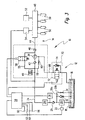
- Fig. 2:
- eine schematisierte Detaildarstellung einer zweiten Kraftstoffpumpe sowie einer Ventileinrichtung des Kraftstoffsystems von Fig. 1;
- Fig. 3:
- eine Darstellung ähnlich Fig. 1 eines zweiten Ausführungsbeispiels eines Kraftstoffsystems; und
- Fig. 4:
- eine Darstellung ähnlich Fig. 1 eines dritten Ausführungsbeispiels eines Kraftstoffsystems.
- Fig.1:
- a schematic block diagram of a first embodiment of a fuel system;
- Fig. 2:
- a schematic detailed representation of a second fuel pump and a valve device of the fuel system of FIG. 1;
- Fig. 3:
- a representation similar to Figure 1 of a second embodiment of a fuel system. and
- Fig. 4:
- a representation similar to FIG. 1 of a third embodiment of a fuel system.
In Fig. 1 trägt ein Kraftstoffsystem insgesamt das
Bezugszeichen 10. Es umfasst einen Niederdruckbereich 12
und einen Hochdruckbereich 14. Zunächst zum
Niederdruckbereich 12:In Fig. 1, a fuel system as a whole carries that
Dieser umfasst einen Vorratsbehälter 16, in dem Kraftstoff
18 bevorratet wird. Der Kraftstoff 18 wird aus dem
Vorratsbehälter 16 von einer ersten Kraftstoffpumpe 20
gefördert. Bei dieser handelt es sich um eine elektrische
Kraftstoffpumpe, welche von einem Taktmodul 22 angesteuert
wird. Die elektrische Kraftstoffpumpe 20 fördert in eine
Niederdruck-Kraftstoffleitung 24. In dieser ist nach der
elektrischen Kraftstoffpumpe 20 in Strömungsrichtung
gesehen zunächst ein Rückschlagventil 26 und dann ein
Filter 28 angeordnet. In Strömungsrichtung gesehen noch vor
dem Rückschlagventil 26 zweigt von der Niederdruck-Kraftstoffleitung
24 eine Zweigleitung 30 ab, welche zum
Vorratsbehälter 16 zurückführt. Die Zweigleitung 30
verzweigt sich in zwei parallele Zweige 30a und 30b. Im
Zweig 30a ist ein Druckbegrenzungsventil 32 angeordnet,
wohingegen im Zweig 30b eine Drossel 34 vorgesehen ist. Der
Druck in der Niederdruck-Kraftstoffleitung 24 wird von
einem Drucksensor 36 erfasst.This includes a
Die Niederdruck-Kraftstoffleitung 24 führt zu einer zweiten
Kraftstoffpumpe 38. Diese wird auf hier nicht näher
dargestellte Weise von der Kurbelwelle einer
Brennkraftmaschine (nicht dargestellt) angetrieben. Bei der
zweiten Kraftstoffpumpe 38 handelt es sich um eine Ein-Kolben-Hochdruckpumpe.
Stromaufwärts von der Hochdruckpumpe
38 sind in der Niederdruck-Kraftstoffleitung 24 noch ein
Druckdämpfer 40 und ein Rückschlagventil 42 angeordnet.The low
Ausgangsseitig fördert die Hochdruckpumpe 38 in eine
Kraftstoffleitung 44, welche über ein Rückschlagventil 46
zu einer Kraftstoff-Sammelleitung 48 führt. An die
Kraftstoff-Sammelleitung 48 sind wiederum Kraftstoff-Einspritzventile
50 angeschlossen, welche den Kraftstoff in
einen nicht dargestellten Brennraum der Brennkraftmaschine
einspritzen. Der Druck in der Kraftstoff-Sammelleitung 48
wird von einem Drucksensor 52 erfasst.On the output side, the high-
Um einen Überdruck in der Kraftstoff-Sammelleitung 48 zu
vermeiden, welcher die Funktionstüchtigkeit der
Einspritzventile 50 beeinträchtigen könnte, ist an der
Kraftstoff-Sammelleitung 48 ein Druckbegrenzungsventil 54
vorgesehen, welches über eine Leitung 55 fluidisch wiederum
mit der Niederdruck-Kraftstoffleitung 24 verbunden ist. Der
Druck in der Kraftstoffleitung 44 und der Kraftstoff-Sammelleitung
48, also im Hochdruckbereich 14 des
Kraftstoffsystems 10, wird über ein Mengensteuerventil 56
gesteuert, welches den zwischen dem Rückschlagventil 46 und
der Hochdruckpumpe 38 gelegenen Bereich der
Kraftstoffleitung 44 mit dem zwischen dem Rückschlagventil
42 und dem Druckdämpfer 40 gelegenen Bereich der
Niederdruck-Kraftstoffleitung 24 verbindet.To overpressure in the
Das Kraftstoffsystem 10 umfasst auch ein Steuer- und
Regelgerät 58, welches u.a. Signale von einem
Temperatursensor 60 erhält, mit dem die Temperatur des
Kühlwassers der Brennkraftmaschine erfasst wird. In
gleicher Weise ist auch ein Sensor 62 für die Erfassung der
Temperatur der Ansaugluft vorgesehen, der ebenfalls Signale
an das Steuer- und Regelgerät 58 abgibt. Ein Sensor 64
liefert dem Steuer- und Regelgerät 58 Informationen über
die Drehzahl der Brennkraftmaschine und ein Sensor 66
entsprechende Informationen bezüglich der aktuellen Last
der Brennkraftmaschine. Ferner erhält das Steuer- und
Regelgerät 58 noch Signale vom Drucksensor 36 des
Niederdruckbereichs 12 des Kraftstoffsystems 10 sowie vom
Drucksensor 52 des Hochdruckbereichs 14 des
Kraftstoffsystems 10.The
Von der Hochdruckpumpe 38 führt eine Leckageleitung 68
zurück zum Vorratsbehälter 16. In der Leckageleitung 68
ist, unmittelbar bei der Hochdruckpumpe 38, eine
Ventileinrichtung 70 vorhanden. Bei der in Fig. 1 nur
symbolischen Darstellungsweise verfügt die
Ventileinrichtung 70 über eine Absperrfunktion 72 und eine
Druckbegrenzungsfunktion 74, die parallel zueinander
geschaltet sind.A
Die Hochdruckpumpe 38 und die Ventileinrichtung 70 werden
nun unter Bezugnahme auf Fig. 2 im Detail erläutert:The
Wie bereits oben erläutert wurde, handelt es sich bei der
Hochdruckpumpe um eine Ein-Kolben-Pumpe. Der Kolben trägt
in Fig. 2 das Bezugszeichen 76. Er wird über einen
Nockenantrieb 78 angetrieben. Der Kolben 76 ist in einem
Zylindergehäuse 80 geführt. Die Oberseite des Kolbens 76
und das Zylindergehäuse 80 begrenzen einen Pumpraum 82. Der
Pumpraum 82 wird gegenüber dem Nockenantrieb 78 durch eine
Spaltdichtung abgedichtet, welche zwischen dem Kolben 76
und dem Zylindergehäuse 80 gebildet ist. Ferner ist eine
gehäusefeste Kolbendichtung 84 vorgesehen. Die
Leckageleitung 68 zweigt von einer Ringnut 86 unmittelbar
oberhalb der Kolbendichtung 84 ab. Hierdurch wird im
Betrieb die Kolbendichtung 84 entlastet.As already explained above, the
High pressure pump around a single piston pump. The piston carries
in Fig. 2,
In der Ventileinrichtung 70 ist nur ein einziges
Ventilglied 88 vorhanden, welches für die Absperrfunktion
72 ebenso wie für die Druckbegrenzungsfunktion 74 verwendet
wird. Das Ventilglied 88 umfasst einen länglichen in einem
Gehäuse 89 geführten Kolben 90, der an seinem in Fig. 2
oberen Ende eine Platte 92 aus einem weichmagnetischen
Werkstoff trägt. Die Platte 92 wird von einer Druckfeder 94
beaufschlagt, durch welche die untere Stirnfläche des
Kolbens 90 des Ventilglieds 88 gegen einen Ringsteg 96
beaufschlagt wird, der in einem Strömungsraum 98 hinter
einem Einlass 100 der Ventileinrichtung 70 gebildet ist. Am
Strömungsraum 98 ist ein radialer Auslass 102 vorgesehen,
an den der zum Vorratsbehälter 16 führende Abschnitt der
Leckageleitung 68 angeschlossen ist.There is only one in the
Das Gehäuse 89 der Ventileinrichtung 70 ist nach oben hin
durch einen Deckel 104 abgeschlossen, welcher auf seiner
dem Ventilglied 88 zugewandten Innenseite eine
konzentrische Ringnut (ohne Bezugszeichen) aufweist, in die
ein ringförmiger Elektromagnet 106 eingesetzt ist. Der
Deckel 104 der Ventileinrichtung 70 ist mit dem Gehäuse 89
durch eine Verstemmung 108 unlösbar verbunden. The
Das in den Fig. 1 und 2 dargestellte Kraftstoffsystem 10
arbeitet folgendermaßen:The
Im Normalbetrieb, also bei normaler Betriebstemperatur der
Brennkraftmaschine (dies wird vom Steuer- und Regelgerät 58
aufgrund der vom Temperatursensor 60, dem Temperatursensor
62, dem Drehzahlsensor 64 und dem Lastsensor 66
bereitgestellten Signale ermittelt), wird der Kraftstoff 18
aus dem Vorratsbehälter 16 von der elektrischen
Kraftstoffpumpe 20 in die Kraftstoffleitung 24 zur
Hochdruckpumpe 38 gefördert. Die Hochdruckpumpe 38 fördert
den von der elektrischen Kraftstoffpumpe 20 vorverdichteten
Kraftstoff 18 weiter unter nochmaliger Druckerhöhung in die
Kraftstoffleitung 44 zur Kraftstoff-Sammelleitung 48 hin.
Durch den Druckbegrenzer 32 und die Drossel 34, die im
Übrigen als modulare Einheit mit der elektrischen
Kraftstoffpumpe 20 ausgebildet sind, wird beim Einschalten
der elektrischen Kraftstoffpumpe die Herstellung eines
stabilen Vordrucks im Niederdruckbereich 12 des
Kraftstoffsystems 10 beschleunigt und erleichtert.In normal operation, i.e. at normal operating temperature
Internal combustion engine (this is controlled by the control and regulating
Der Drucksensor 52 und das Mengensteuerventil 56 sind Teil
einer geschlossenen Regelstrecke, über die die von der
Hochdruckpumpe 38 in den Hochdruckbereich 14 des
Kraftstoffsystems 10 geförderte Kraftstoffmenge eingestellt
wird. Die Ventileinrichtung 70 wird vom Steuer- und
Regelgerät 58 so angesteuert, dass ein freier Durchfluss
durch die Leckageleitung 68 von der Hochdruckpumpe 38 zum
Vorratsbehälter 16 hin möglich ist. Die Steuerung und
Regelung erfolgt gemäß einem Computerprogramm, welches im
Steuer- und Regelgerät abgespeichert ist. Hierdurch ist es
möglich, dass Kraftstoff, welcher durch die Spaltdichtung
zwischen Kolben 76 und Zylindergehäuse 80 hindurch bis zur
Ringnut 86 gelangt, über die Leckageleitung 68 zum
Vorratsbehälter 16 zurückfließen kann. Hierdurch wird
erreicht, dass die Kolbendichtung 84 druckentlastet ist. The
Die Öffnung der Ventileinrichtung 70, also die
Deaktivierung der Absperrfunktion 72, wird dadurch
erreicht, dass der Ringmagnet 106 bestromt wird. Der
Ringmagnet 106 zieht somit die weichmagnetische Platte 92
an, welche wiederum den Kolben 90 von dem einen Ventilsitz
bildenden Ringsteg 96 abhebt.The opening of the
Wird die Brennkraftmaschine ausgeschaltet, wird vom Steuerund
Regelgerät 58 über den Temperatursensor 60 für das
Kühlwasser geprüft, ob die Brennkraftmaschine heiß ist. Ist
dies der Fall, wird die Absperrfunktion 72 der
Ventileinrichtung 70 vom Steuer- und Regelgerät 58
deaktiviert. Der Ringmagnet 106 ist somit stromlos, wodurch
der Kolben 90 von der Druckfeder 94 gegen den Ringsteg 96
gedrückt wird. Der Weg von der Hochdruckpumpe 38 über die
Leckageleitung 68 zum Vorratsbehälter 16 ist somit
blockiert. Gleichzeitig wird vom Steuer- und Regelgerät 58
das Modul 22 der elektrischen Kraftstoffpumpe 20 so
angesteuert, dass für einen kurzen Zeitraum die elektrische
Kraftstoffpumpe 20 weiter im Betrieb ist. Dies führt zu
einer Erhöhung des Drucks des Kraftstoffs in der
Niederdruck-Kraftstoffleitung 24 bis zu dem durch das
Druckbegrenzungsventil 32 und die Druckbegrenzungsfunktion
74 der Ventileinrichtung 70 vorgegebenen maximalen Druck.If the internal combustion engine is switched off, the control and
Es bietet sich insoweit an, dass der durch die
Druckbegrenzungsfunktion 74 der Ventileinrichtung 70
vorgegebene maximale Druck und der durch das
Druckbegrenzungsventil 32 vorgegebene maximale Druck in
etwa gleich sind. Die Druckbegrenzungsfunktion 74 der
Ventileinrichtung 70 wird dadurch bereitgestellt, dass bei
einer Druckdifferenz zwischen dem Einlass 100 und dem
Auslass 102 der Ventileinrichtung 70 der Kolben 90 gegen
die Vorspannkraft der Druckfeder 94 beaufschlagt wird.
Übersteigt die Druckdifferenz ein bestimmtes Maß, hebt der
Kolben 90 vom Ringsteg 96 ab. Dies gibt den Weg frei für am
Einlass 100 der Ventileinrichtung 70 unter Überdruck
stehenden Kraftstoff.In this respect, it makes sense that the through the
Nach dem Abstellen der Brennkraftmaschine kann es aufgrund
von Wärmeleitung zu einer Erwärmung der Niederdruck-Kraftstoffleitung
24 kommen. Hierdurch wird auch der
Kraftstoff 18 in der Niederdruck-Kraftstoffleitung 24
erwärmt und dehnt sich aus. Dies führt wiederum zu einer
Druckerhöhung innerhalb der Niederdruck-Kraftstoffleitung
24. Um eine Beschädigung von Komponenten der Niederdruck-Kraftstoffleitung
bzw. insgesamt des Niederdruckbereichs 12
zu vermeiden, ist die Vorspannkraft der Feder 94 bzw. der
Öffnungsdruck der Druckbegrenzungsfunktion 74 der
Ventileinrichtung 70 entsprechend gewählt.After turning off the engine it may be due to
from heat conduction to heating the low
Die Leckageleitung 68 und die in dieser angeordnete
Ventileinrichtung 70 ermöglichen es also, dass beim
Abstellen einer heißen Brennkraftmaschine ein erhöhter
Druck in der Niederdruck-Kraftstoffleitung 24
aufrechterhalten werden kann, ohne dass eine Gefahr für
eine Beschädigung von Komponenten im Niederdruckbereich 12
des Kraftstoffsystems 10 aufgrund einer durch eine
Erwärmung des sich in der Niederdruck-Kraftstoffleitung 24
befindlichen Kraftstoffs besteht. Das Startverhalten einer
heißen Brennkraftmaschine wird durch ein solches
Kraftstoffsystem 10 somit entscheidend verbessert, ohne
dass die Lebensdauer der Komponenten beeinträchtigt wäre.The
Nun wird auf Fig. 3 Bezug genommen, in der ein zweites
Ausführungsbeispiel eines Kraftstoffsystems 10 dargestellt
ist. Solche Elemente oder Teile, welche äquivalente
Funktionen zu Elementen oder Teilen des in den Fig. 1 und 2
beschriebenen Ausführungsbeispiels aufweisen, tragen die
gleichen Bezugszeichen und sind nicht nochmals im Detail
erläutert. 3, in which a second
Embodiment of a
Im Gegensatz zu dem in den Fig. 1 und 2 dargestellten
Ausführungsbeispiel ist bei dem in Fig. 3 dargestellten
Ausführungsbeispiel die Ventileinrichtung 70 nicht in der
Nähe der Hochdruckpumpe 38, sondern im Bereich des
Vorratsbehälters 16 angeordnet. Ferner ist im Bereich der
Hochdruckpumpe 38 eine Bypassleitung 110 vorgesehen, welche
von einem zwischen dem Druckdämpfer 40 und dem
Rückschlagventil 42 der Niederdruck-Kraftstoffleitung 24
gelegenen Bereich zu einem zwischen der Hochdruckpumpe 38
und der Ventileinrichtung 70 gelegenen Bereich der
Leckageleitung 68 führt. In der Bypassleitung 110 ist eine
Drossel 112 angeordnet. Die Bypassleitung 110 und die
Drossel 112 sind aus folgendem Grund vorhanden:In contrast to that shown in FIGS. 1 and 2
Embodiment is in that shown in Fig. 3
Embodiment, the
Wenn die Ventileinrichtung 70, wie im vorliegenden
Ausführungsbeispiel, nicht in der Nähe der Hochdruckpumpe
38 angeordnet ist, kann es während des normalen Betriebs
des Kraftstoffsystems 10 dazu kommen, dass durch
Wärmeleitung von der Brennkraftmaschine her die
Leckageleitung 68 und der sich in ihr befindliche
Kraftstoff erwärmt werden. Da im Normalbetrieb ja die
Ventileinrichtung 70 geöffnet ist, ist dann der sich in der
Leckageleitung 68 befindliche Kraftstoff im Wesentlichen
drucklos. Aufgrund der Erwärmung kann dieser Kraftstoff in
der Leckageleitung 68 somit, verdampfen. Wird nun nach dem
Abstellen der Brennkraftmaschine die Ventileinrichtung 70
geschlossen, würde auch die sich in der Leckageleitung 68
befindliche Dampfblase mit eingeschlossen. Dies könnte beim
Wiederanlassen zu einem Problem führen.If the
Um dies zu vermeiden, wird über die Bypassleitung 110 auch
im Normalbetrieb Kraftstoff am Pumpraum 82 der
Hochdruckpumpe 38 vorbei in die Leckageleitung 68
hineingeleitet. Dies ist möglich, da die elektrische
Kraftstoffpumpe 20 der Hochdruckpumpe 38 normalerweise eine
größere Kraftstoffmenge bereitstellt als von dieser weiter
in den Hochdruckbereich 14 des Kraftstoffsystems 10
gefördert wird. Im Normalbetrieb des Kraftstoffsystems 10
stellt sich also ein mehr oder weniger konstanter
Kraftstofffluss durch die Leckageleitung 68 zum
Vorratsbehälter 16 zurück ein. Hierdurch wird zum einen
vermieden, dass in der Leckageleitung 68 "stehender"
Kraftstoff sich erwärmt und verdampft, und zum anderen wird
erreicht, dass eventuell bereits gebildete Dampfblasen zum
Vorratsbehälter 16 hin ausgespült werden.To avoid this,
Über die Drossel 112 wird die am Pumpraum 82
vorbeigeleitete Kraftstoffmenge so begrenzt, dass der über
die Leckageleitung 68 zurückfließende und leicht erwärmte
Kraftstoff den sich im Vorratsbehälter 16 befindlichen
Kraftstoff nicht unzulässig erwärmt, was dort wiederum zu
Verdampfungsproblemen führen könnte. Wird nun die
Brennkraftmaschine abgestellt und die Ventileinrichtung 70
geschlossen, kann davon ausgegangen werden, dass sich in
der Leckageleitung 68 im Wesentlichen ausschließlich
flüssiger Kraftstoff und keine Dampfblasen befinden.The
Bei diesem Ausführungsbeispiel kann also die
Ventileinrichtung 70 im Bereich des Vorratsbehälters 16
angeordnet werden, was bisweilen aus Platzgründen
wünschenswert ist, und gleichzeitig wird ein sicheres
Heißstartverhalten und ein zuverlässiger Betrieb der
Brennkraftmaschine ermöglicht.In this embodiment, the
In Fig. 4 ist ein weiteres Ausführungsbeipiel eines
Kraftstoffsystems 10 dargestellt. Auch hier tragen solche
Elemente und Teile, welche äquivalente Funktionen zu den in
den Fig. 1 - 3 dargestellten Ausführungsbeispielen
aufweisen, die gleichen Bezugszeichen und sind nicht
nochmals im Detail erläutert.4 is another exemplary embodiment of a
Im Gegensatz zu dem in Fig. 3 dargestellten
Ausführungsbeispiel ist bei dem in Fig. 4 gezeigten
Ausführungsbeispiel der zwischen dem Filter 28 und dem
Druckdämpfer 40 gelegene Bereich der Niederdruck-Kraftstoffleitung
24 über eine Verbindungsleitung 114, ein
Absperrventil 116 und ein Druckregelventil 118 mit dem
zwischen der Hochdruckpumpe 38 und der Ventileinrichtung 70
gelegenen Bereich der Leckageleitung 68 verbindbar. Ferner
ist die Leitung 55, in der das Mengensteuerventil 56
angeordnet ist, über eine Spülleitung 120 mit dem zwischen
dem Absperrventil 116 und dem Druckregelventil 118
gelegenen Bereich der Verbindungsleitung 114 verbunden. In
der Spülleitung 120 ist eine Drossel 122 angeordnet.In contrast to that shown in Fig. 3
Embodiment is in that shown in Fig. 4
Embodiment between the
Claims (14)
- Fuel system (10) for delivery of fuel (18) for an internal combustion engine, with a tank (16), with a first fuel pump (20) which is connected on the inlet side to the tank (16), with a second fuel pump (38) which is connected on the inlet side to the first fuel pump (20), with at least one injection valve (50) which is connected to the second fuel pump (38) and can supply fuel (18) at least indirectly to a combustion space, and with a leakage line provided between the second fuel pump and the tank, characterized in that the leakage line (68) has arranged in it a valve device (70) having a shut-off function (72) and a pressure-limiting function (74) which are connected in parallel.
- Fuel system (10) according to Claim 1, characterized in that the same valve member (88) is used for both functions (72, 74) in the valve device (70).
- Fuel system (10) according of the preceding claims, characterized in that the shut-off function (72) of the valve device (70) is activateable electrically.
- Fuel system (10) according to Claim 3, characterized in that the valve device (70) comprises a valve element (88) which is prestressed (94) for providing the pressure-limiting function (74) and which is actuable electrically, counter to the prestressing force, in order to cancel the shut-off function (72).
- Fuel system (10) according to one of the preceding claims, characterized in that the valve device (70) is arranged in the region of the internal combustion engine, in particular in the region of the second fuel pump (38).
- Fuel system (10) according to one of the preceding claims, characterized in that the valve device (70) is arranged in the region of the tank (16), and a bypass line (110) with a throttle point (112) is provided at the second fuel pump (38), the said bypass line leading from the inlet of the second fuel pump (38) to the leakage line (68), and the cross-section of the throttle point (112) is selected such that, during normal operation, the rise in temperature of the fuel (18) in the tank (16) is lower than the limit value.
- Method for operating the fuel system (10) according to one of the preceding claims, characterized in that the shut-off function (72) of the valve device (70) is activated immediately after the stopping of the internal combustion engine and is deactivated immediately after the starting of the internal combustion engine.
- Method according to Claim 7, characterized in that the first fuel pump (20) still remains in operation for a limited period of time after the stopping of the internal combustion engine.
- Method according to either one of Claims 7 and 8, characterized in that the parameters (60, 62, 64, 66) relevant for a hot start of the internal combustion engine are detected, and the activation of the first fuel pump (20) and/or of the valve device (70) takes place as a function of the detected parameters.
- Method according to Claim 9, characterized in that the parameters comprise a cooling-water temperature (60) and/or an intake-air temperature (62) and/or a rotational speed (64) and/or a load (66) of the internal combustion engine.
- Method according to Claims 7 to 10, characterized in that the pressure of the inlet of the second fuel pump (38) is set via the rotational speed of the first fuel pump (20).
- Computer program, characterized in that it is suitable for carrying out the method according to one of Claims 7 to 11 when the latter is executed on a computer.
- Computer program according to Claim 12, characterized in that it is stored on a memory, in particular on a flash memory.
- Control and/or regulating apparatus (58) for controlling and/or regulating the fuel system (10) according to one of Claims 1 to 6, characterized in that it is provided with a computer program according to either one of Claims 12 or 13.
Applications Claiming Priority (3)
| Application Number | Priority Date | Filing Date | Title |
|---|---|---|---|
| DE10106095 | 2001-02-08 | ||
| DE10106095A DE10106095A1 (en) | 2001-02-08 | 2001-02-08 | Fuel system, method for operating the fuel system, computer program and control and / or regulating device for controlling the fuel system |
| PCT/DE2002/000427 WO2002063158A1 (en) | 2001-02-08 | 2002-02-06 | Fuel system, method for operating the fuel system, computer programme and control device and/or regulator for controlling said system |
Publications (2)
| Publication Number | Publication Date |
|---|---|
| EP1360406A1 EP1360406A1 (en) | 2003-11-12 |
| EP1360406B1 true EP1360406B1 (en) | 2004-06-30 |
Family
ID=7673521
Family Applications (1)
| Application Number | Title | Priority Date | Filing Date |
|---|---|---|---|
| EP02708213A Expired - Lifetime EP1360406B1 (en) | 2001-02-08 | 2002-02-06 | Fuel system, method for operating the fuel system, computer programme and control device and/or regulator for controlling said system |
Country Status (6)
| Country | Link |
|---|---|
| US (1) | US6769414B2 (en) |
| EP (1) | EP1360406B1 (en) |
| JP (1) | JP2004518071A (en) |
| KR (1) | KR20020086739A (en) |
| DE (2) | DE10106095A1 (en) |
| WO (1) | WO2002063158A1 (en) |
Families Citing this family (45)
| Publication number | Priority date | Publication date | Assignee | Title |
|---|---|---|---|---|
| JP2003120457A (en) * | 2001-09-18 | 2003-04-23 | Hyundai Motor Co Ltd | System and method for fuel injection pressure control |
| DE10212870A1 (en) * | 2002-03-22 | 2003-10-02 | Volkswagen Ag | Fuel supply system of IC engine with high pressure injection has valve fitted in HP pump leakage pipe |
| US6718948B2 (en) * | 2002-04-01 | 2004-04-13 | Visteon Global Technologies, Inc. | Fuel delivery module for petrol direct injection applications including supply line pressure regulator and return line shut-off valve |
| DE10237592A1 (en) * | 2002-08-16 | 2004-03-11 | Robert Bosch Gmbh | Fuel injection device for an internal combustion engine |
| DE10260775A1 (en) * | 2002-12-23 | 2004-07-01 | Daimlerchrysler Ag | Fuel supply system for internal combustion engines with direct injection |
| DE10313133B3 (en) * | 2003-03-24 | 2004-09-23 | Robert Bosch Gmbh | Operating parameters monitoring system for internal combustion engine incorporates pressure sensor in fuel leakage collection line returning fuel to tank |
| DE10315318A1 (en) * | 2003-04-04 | 2004-10-14 | Robert Bosch Gmbh | Method for operating an internal combustion engine |
| JP4127188B2 (en) * | 2003-10-30 | 2008-07-30 | トヨタ自動車株式会社 | Fuel supply device for internal combustion engine |
| DE102004003113A1 (en) * | 2004-01-21 | 2005-08-11 | Siemens Ag | Device for controlling a pressure in a fuel supply line |
| US7066152B2 (en) * | 2004-09-03 | 2006-06-27 | Ford Motor Company | Low evaporative emission fuel system depressurization via solenoid valve |
| WO2006053792A1 (en) * | 2004-11-17 | 2006-05-26 | Siemens Aktiengesellschaft | Pump assembly |
| DE102005001577B4 (en) * | 2005-01-13 | 2017-04-06 | Robert Bosch Gmbh | Method and device for controlling an internal combustion engine |
| DE102005033638A1 (en) * | 2005-07-19 | 2007-01-25 | Robert Bosch Gmbh | Fuel conveyor, in particular for an internal combustion engine |
| JP2007285235A (en) * | 2006-04-18 | 2007-11-01 | Honda Motor Co Ltd | Fuel supply device for diesel engine |
| JP2008057451A (en) * | 2006-08-31 | 2008-03-13 | Hitachi Ltd | High-pressure fuel supply pump |
| DE102006053847A1 (en) * | 2006-11-14 | 2008-05-15 | Hydraulik-Ring Gmbh | High pressure fuel system with volume compensation, especially for the cooling phase of the high pressure system |
| US7527043B2 (en) * | 2007-07-05 | 2009-05-05 | Caterpillar Inc. | Liquid fuel system with anti-drainback valve and engine using same |
| KR100956025B1 (en) * | 2008-06-26 | 2010-05-06 | 한국기계연구원 | Improvement hot starting control method for liquid phase lpg injection system |
| NL2001772C2 (en) * | 2008-07-07 | 2010-01-11 | Teleflex Gfi Europ B V | Dual fuel e.g. gasoline, injection system for internal combustion engine of motor vehicle, has high pressure pump for pressurizing fuels, and injector injecting pressurized fuels into combustion chamber of engine |
| ATE549498T1 (en) * | 2008-07-07 | 2012-03-15 | Impco Technologies B V | DUAL FUEL INJECTION SYSTEM AND MOTOR VEHICLE HAVING SUCH AN INJECTION SYSTEM |
| ATE542994T1 (en) * | 2008-08-29 | 2012-02-15 | Delphi Tech Holding Sarl | IMPROVED FUEL PRESSURE REGULATION SYSTEM AND IMPROVED FUEL PRESSURE REGULATOR FOR USE THEREIN |
| JP4736142B2 (en) * | 2009-02-18 | 2011-07-27 | 株式会社デンソー | High pressure pump |
| DE102010002801A1 (en) * | 2010-03-12 | 2011-09-15 | Robert Bosch Gmbh | Fuel injection system of an internal combustion engine |
| SE534969C2 (en) * | 2010-05-25 | 2012-03-06 | Ec1 Invent Ab | Heat exchange medium comprising a synthetic diesel |
| RU2555607C2 (en) * | 2010-07-14 | 2015-07-10 | Вольво Ластвагнар Аб | Fuel delivery system with vapour discharge function |
| RU2562341C2 (en) * | 2010-12-22 | 2015-09-10 | Вольво Ластвагнар Аб | Fuel injection system with high-pressure pump |
| US9316187B2 (en) | 2011-01-18 | 2016-04-19 | Carter Fuel Systems, Llc | Diesel fuel system with advanced priming |
| CA2766000A1 (en) * | 2011-01-28 | 2012-07-28 | Jack Lange | Fuel oil supply system from a remote source including recirculated heating of fuel oil and supplemented supply pressure |
| NL2006992C2 (en) | 2011-06-24 | 2013-01-02 | Indopar B V | Method of switching from a liquefied gas fuel to a liquid fuel being provided to a direct injection combustion engine, and direct injection bi-fuel system for such an engine. |
| JP5678838B2 (en) * | 2011-08-10 | 2015-03-04 | トヨタ自動車株式会社 | Fuel pumping device and fuel supply system |
| JP2013068161A (en) * | 2011-09-22 | 2013-04-18 | Yamaha Motor Co Ltd | Saddle-type vehicle |
| WO2013067226A1 (en) * | 2011-11-01 | 2013-05-10 | Pc/Rc Products, L.L.C. | Throttle body fuel reservoir |
| CN102425516B (en) * | 2011-11-03 | 2014-04-16 | 北京理工大学 | Multi-valve oil spraying system and multi-valve oil spraying method |
| US20130312706A1 (en) * | 2012-05-23 | 2013-11-28 | Christopher J. Salvador | Fuel system having flow-disruption reducer |
| KR101338805B1 (en) * | 2012-06-14 | 2013-12-06 | 현대자동차주식회사 | Feul supply apparatus for gdi engine having reduced pressure pulsation |
| SE540028C2 (en) * | 2014-07-08 | 2018-02-27 | Scania Cv Ab | Combustion engine fuel system, internal combustion engine with such a fuel system, vehicles with such a fuel system and a method for dampening pressure fluctuations of a fuel filter device in a fuel system |
| DE102014014475A1 (en) * | 2014-09-27 | 2016-03-31 | Man Diesel & Turbo Se | Fuel pump |
| DE102014220742B4 (en) * | 2014-10-14 | 2021-03-18 | Vitesco Technologies GmbH | Method for operating a fuel supply system for an internal combustion engine |
| JP6387812B2 (en) * | 2014-12-05 | 2018-09-12 | 株式会社デンソー | High pressure pump and fuel supply system using the same |
| DE102016200232A1 (en) * | 2016-01-12 | 2017-07-13 | Continental Automotive Gmbh | Fuel injection system |
| GB2546809B (en) * | 2016-02-01 | 2018-05-09 | Rolls Royce Plc | Low cobalt hard facing alloy |
| GB2546808B (en) * | 2016-02-01 | 2018-09-12 | Rolls Royce Plc | Low cobalt hard facing alloy |
| DE102016123055A1 (en) * | 2016-11-30 | 2018-05-30 | Man Diesel & Turbo Se | Fuel supply system and power distribution block |
| GB2560975A (en) * | 2017-03-31 | 2018-10-03 | Delphi Int Operations Luxembourg Sarl | High pressure fuel pump |
| BR102020024417A2 (en) * | 2020-11-30 | 2022-06-07 | Robert Bosch Limitada | System and method of managing the temperature of fuel injected into internal combustion engines from a mixture of an air and fuel flow applicable to a vehicle |
Family Cites Families (7)
| Publication number | Priority date | Publication date | Assignee | Title |
|---|---|---|---|---|
| US5558068A (en) * | 1994-05-31 | 1996-09-24 | Zexel Corporation | Solenoid valve unit for fuel injection apparatus |
| DE19780251C2 (en) * | 1996-02-29 | 2001-02-22 | Mitsubishi Motors Corp | Fuel supply system for an internal combustion engine |
| DE19612412B4 (en) * | 1996-03-28 | 2006-07-06 | Siemens Ag | Control for a pressurized fluid supply system, in particular for the high pressure in a fuel injection system |
| DE19648690A1 (en) * | 1996-11-25 | 1998-05-28 | Bosch Gmbh Robert | Fuel injection system |
| DE19753155A1 (en) * | 1997-11-29 | 1999-06-02 | Mannesmann Rexroth Ag | Fuel supply system for an internal combustion engine and high pressure pump used therein |
| DE19818421B4 (en) * | 1998-04-24 | 2017-04-06 | Robert Bosch Gmbh | Fuel supply system of an internal combustion engine |
| JP2001055961A (en) * | 1999-08-11 | 2001-02-27 | Mitsubishi Electric Corp | High pressure fuel supplying device |
-
2001
- 2001-02-08 DE DE10106095A patent/DE10106095A1/en not_active Ceased
-
2002
- 2002-02-06 US US10/257,025 patent/US6769414B2/en not_active Expired - Fee Related
- 2002-02-06 JP JP2002562875A patent/JP2004518071A/en active Pending
- 2002-02-06 EP EP02708213A patent/EP1360406B1/en not_active Expired - Lifetime
- 2002-02-06 WO PCT/DE2002/000427 patent/WO2002063158A1/en active IP Right Grant
- 2002-02-06 KR KR1020027012997A patent/KR20020086739A/en not_active Application Discontinuation
- 2002-02-06 DE DE50200579T patent/DE50200579D1/en not_active Expired - Fee Related
Also Published As
| Publication number | Publication date |
|---|---|
| EP1360406A1 (en) | 2003-11-12 |
| WO2002063158A1 (en) | 2002-08-15 |
| JP2004518071A (en) | 2004-06-17 |
| KR20020086739A (en) | 2002-11-18 |
| DE10106095A1 (en) | 2002-08-29 |
| DE50200579D1 (en) | 2004-08-05 |
| US20030154959A1 (en) | 2003-08-21 |
| US6769414B2 (en) | 2004-08-03 |
Similar Documents
| Publication | Publication Date | Title |
|---|---|---|
| EP1360406B1 (en) | Fuel system, method for operating the fuel system, computer programme and control device and/or regulator for controlling said system | |
| DE19742180C2 (en) | Injection system for an internal combustion engine and method for regulating an injection system | |
| EP2205846B1 (en) | Method for controlling a fuel injection system of an internal combustion engine | |
| EP2217795B1 (en) | Fuel injection system for an internal combustion engine, comprising a hydrocarbon injector | |
| DE102005033638A1 (en) | Fuel conveyor, in particular for an internal combustion engine | |
| DE10153185A1 (en) | Fuel injection system with improved delivery control | |
| DE10115324A1 (en) | Fuel system | |
| EP1348072B1 (en) | Method, computer program and control and/or regulation device for operating an internal combustion engine, and corresponding internal combustion engine | |
| WO2014060292A1 (en) | Method for operating a fuel injection system with a fuel filter heating process, and fuel injection system | |
| DE10323874A1 (en) | Method for operating an internal combustion engine, fuel system and a volume flow control valve | |
| DE102006018164B3 (en) | Fuel injection system controlling method for internal combustion engine, involves adjusting volume flow control valve depending on control value for volume flow control valve and controlling of pressure control valve | |
| EP1427931B1 (en) | Method, computer programme, control and/or regulation device for operation of an internal combustion engine and fuel system for an internal combustion engine | |
| DE10036772C2 (en) | Method for operating a fuel metering system of a direct injection internal combustion engine | |
| WO2007051675A1 (en) | Fuel system of an internal combustion engine | |
| EP1262658B1 (en) | Fuel system for supplying fuel for an internal combustion engine | |
| DE102010004215B4 (en) | A device for preventing engine stall in a vehicle equipped with a diesel injection system | |
| DE102005000639A1 (en) | Pressure modulated common rail injector and injection system | |
| EP1117929B1 (en) | Fuel injection system | |
| EP1262659B1 (en) | Fuel system for an internal combustion engine | |
| DE102005061362B3 (en) | Pressure control valve for injection system of multi-cylinder internal combustion engine, has closing body provided in non-controlled condition of actuator in closing position, where force acting on body is changed by controlling actuator | |
| DE102008056001B4 (en) | Internal combustion engine with flow-optimized high-pressure fuel pump | |
| DE19738502A1 (en) | High pressure generation system | |
| DE102006060299A1 (en) | Method for operating a fuel system for an internal combustion engine | |
| DE10315318A1 (en) | Method for operating an internal combustion engine | |
| DE19900564C2 (en) | Common Rail System |
Legal Events
| Date | Code | Title | Description |
|---|---|---|---|
| PUAI | Public reference made under article 153(3) epc to a published international application that has entered the european phase |
Free format text: ORIGINAL CODE: 0009012 |
|
| 17P | Request for examination filed |
Effective date: 20030908 |
|
| AK | Designated contracting states |
Kind code of ref document: A1 Designated state(s): AT BE CH CY DE DK ES FI FR GB GR IE IT LI LU MC NL PT SE TR |
|
| GRAP | Despatch of communication of intention to grant a patent |
Free format text: ORIGINAL CODE: EPIDOSNIGR1 |
|
| GRAS | Grant fee paid |
Free format text: ORIGINAL CODE: EPIDOSNIGR3 |
|
| GRAA | (expected) grant |
Free format text: ORIGINAL CODE: 0009210 |
|
| AK | Designated contracting states |
Kind code of ref document: B1 Designated state(s): DE FR GB IT |
|
| PG25 | Lapsed in a contracting state [announced via postgrant information from national office to epo] |
Ref country code: GB Free format text: LAPSE BECAUSE OF FAILURE TO SUBMIT A TRANSLATION OF THE DESCRIPTION OR TO PAY THE FEE WITHIN THE PRESCRIBED TIME-LIMIT Effective date: 20040630 |
|
| REG | Reference to a national code |
Ref country code: GB Ref legal event code: FG4D Free format text: NOT ENGLISH |
|
| REG | Reference to a national code |
Ref country code: IE Ref legal event code: FG4D Free format text: GERMAN |
|
| REF | Corresponds to: |
Ref document number: 50200579 Country of ref document: DE Date of ref document: 20040805 Kind code of ref document: P |
|
| GBV | Gb: ep patent (uk) treated as always having been void in accordance with gb section 77(7)/1977 [no translation filed] |
Effective date: 20040630 |
|
| ET | Fr: translation filed | ||
| PG25 | Lapsed in a contracting state [announced via postgrant information from national office to epo] |
Ref country code: IT Free format text: LAPSE BECAUSE OF NON-PAYMENT OF DUE FEES Effective date: 20050206 |
|
| REG | Reference to a national code |
Ref country code: IE Ref legal event code: FD4D |
|
| PLBE | No opposition filed within time limit |
Free format text: ORIGINAL CODE: 0009261 |
|
| STAA | Information on the status of an ep patent application or granted ep patent |
Free format text: STATUS: NO OPPOSITION FILED WITHIN TIME LIMIT |
|
| 26N | No opposition filed |
Effective date: 20050331 |
|
| PG25 | Lapsed in a contracting state [announced via postgrant information from national office to epo] |
Ref country code: DE Free format text: LAPSE BECAUSE OF NON-PAYMENT OF DUE FEES Effective date: 20050901 |
|
| PG25 | Lapsed in a contracting state [announced via postgrant information from national office to epo] |
Ref country code: FR Free format text: LAPSE BECAUSE OF NON-PAYMENT OF DUE FEES Effective date: 20051031 |
|
| REG | Reference to a national code |
Ref country code: FR Ref legal event code: ST Effective date: 20051031 |