EP1359755B1 - Kodiertes Informationssignal - Google Patents
Kodiertes Informationssignal Download PDFInfo
- Publication number
- EP1359755B1 EP1359755B1 EP03101752A EP03101752A EP1359755B1 EP 1359755 B1 EP1359755 B1 EP 1359755B1 EP 03101752 A EP03101752 A EP 03101752A EP 03101752 A EP03101752 A EP 03101752A EP 1359755 B1 EP1359755 B1 EP 1359755B1
- Authority
- EP
- European Patent Office
- Prior art keywords
- length
- representation
- symbols
- bits
- code
- Prior art date
- Legal status (The legal status is an assumption and is not a legal conclusion. Google has not performed a legal analysis and makes no representation as to the accuracy of the status listed.)
- Expired - Lifetime
Links
Images
Classifications
-
- H—ELECTRICITY
- H03—ELECTRONIC CIRCUITRY
- H03M—CODING; DECODING; CODE CONVERSION IN GENERAL
- H03M7/00—Conversion of a code where information is represented by a given sequence or number of digits to a code where the same, similar or subset of information is represented by a different sequence or number of digits
- H03M7/30—Compression; Expansion; Suppression of unnecessary data, e.g. redundancy reduction
- H03M7/40—Conversion to or from variable length codes, e.g. Shannon-Fano code, Huffman code, Morse code
- H03M7/42—Conversion to or from variable length codes, e.g. Shannon-Fano code, Huffman code, Morse code using table look-up for the coding or decoding process, e.g. using read-only memory
Definitions
- the invention relates to a method of encoding information signal blocks, the information signal being sampled and quantized so as to obtain representation symbols, which are subsequently coded into code words of different code word lengths, the probability of occurrence for each representation symbol being determined and code words of a small length being assigned to the representation symbols having a high probability of occurrence and code words of greater length being assigned to representation symbols having a low probability of occurrence in accordance with a predetermined coding technique, information about the length of the code words associated with each representation symbol being generated.
- the invention also relates to a device for forming coded information signal blocks, comprising means for sampling and quantizing an information signal block so as to obtain representation symbols, means for determining the probability of occurrence of each representation symbol and means for forming codes having a variable length for the different representation symbols, which codes are combined into a representation symbol block.
- an information signal is sampled and quantized in order to obtain representation symbols, which representation symbols, if necessary after further processing, are subsequently coded into code words having different code word lengths.
- US-A-5,488,616 discloses a method and a device of the above-mentioned type for variable length coding, wherein information about the length of the code words is generated.
- Huffman codes for the coding of sampled quantized signals.
- a Huffman code can be specified completely by defining the number of code words of any possible code word length.
- the JPEG standard utilizes either fixed Huffman tables, in which a fixed symbol is assigned to each code, or adaptive Huffman tables, in which a code table is determined on the basis of the frequency of occurrence of symbols.
- a representation symbol is also transmitted for each code word in the case of adaptive tables.
- a Huffman coding is based on the idea that an efficient coding with code words of different lengths is possible if the shortest code word length is assigned to those code words which occur most frequently.
- the code words have a length which varies from 1 to 16 and a representation symbol is assigned to each code word, which representation symbols range from 0 to 255.
- the coding in accordance with the JPEG standard is not efficient enough for certain uses, which is particularly so when it is required to transmit a comparatively large number of adaptive Huffman tables for a comparatively small amount of data.
- the invention in particular, but not exclusively, is useful to provide an efficient adaptive Huffman coding in the case that the adaptation frequency of the Huffman tables is high, i.e. the tables are adapted a large number of times per unit of time, and at the same time the number of representation symbols in the information signal to be transmitted comprises all or nearly all permissible representation symbols, as can be the case in, for example, audio and video signals.
- the method of the invention is characterized in that a coded information signal block is generated which is constituted by information about the length of the code word associated with each possible representation symbol, the information about the length of each of the code words being given a number of bits that is identical to the number of bits that is necessary to encode the length of the code word with the maximum length.
- the device according to the invention is characterized by means for generating a coded information block which includes information about the length of the code word associated with each representation symbol, said information having a number of bits that is identical to the number of bits that is necessary to encode the length of the code word with the maximum length.
- the length of the associated Huffman code is transmitted for each possible representation symbol.
- the actual Huffman code words can be derived from this information in an unambiguous manner, as will be explained hereinafter. This requires in the first place that both in the encoder and in the decoder a similar list of symbols is available and the Huffman code word lengths are transmitted in the sequence of this list, while in the second place the Huffman code words derived from the code word lengths are assigned to the symbols in a pre-defined manner.
- the invention is not based on any assumptions with respect to the probability of occurrence of symbols in the signal to be transmitted.
- the representation symbols for audio and video signals are distributed typically symmetrically, for example in accordance with a Gaussian distribution, in such a manner that, when it is assumed that the representation symbols are situated symmetrically relative to the symbol value n and decrease substantially monotonically relative to this vale, the representation symbols whose code words have the smallest lengths occur most frequently and those whose code words have the greatest lengths occur least frequently.
- An even more efficient coding is obtained by minimizing both the sum of the number of bits necessary for specifying the table and the number of bits necessary for coding the actual data.
- the maximum code word length that is assigned decreases less bits are needed to specify the table but more bits are needed to code the data, because the efficiency of the code decreases as the maximum permissible code word length is reduced.
- the efficiency of the Huffman coding can be increased in that a plurality of such representation symbols are grouped into a symbol or a vector of greater length.
- the efficiency of a Huffman code is guaranteed within 1 bit/representation symbol of the entropy of the signal comprising the representation symbols, which means that in the case of a small number of representation symbols the Huffman code is comparatively inefficient. This is solved by said grouping.
- the probabilities which can be determined by determining the number of times that each representation symbols occurs and dividing this number by the total number of representation symbols in the information signal, can be quantized in. for example, 32 levels.
- the above described methods of coding an information signal are particularly suitable for use in a digital audio transmission system in which the signal is divided into subbands and in which the subbands or combinations of subbands are coded by means of the techniques described above for the transmission of the coding information.
- the number of representation symbols in (a combination of) subbands is larger, for example larger than 9, use is made of the exclusive transmission of information about the number of code words of each length, each code word being associated with a representation symbol, if required in combination with information about the longest code word that occurs.
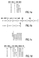
- the following example is based on a sampled quantized signal represented by 7 representation symbols or sample values 0-6.
- An encoder determines the probability of occurrence of each of these 7 representation symbols in the signal block to be transmitted, which can be a signal frame or a subframe, and on the basis thereof a code word of variable length is assigned to each of these representation symbols in accordance with the well-known Huffman coding principle, as described inter alia in the afore-mentioned "JPEG Still Image Compression Standard".
- Figure 1a shows the series of representation symbols and the code words assigned thereto by way of example.
- a code word of a length 2 there are two code words of a length 3 and four code words of a length 4.
- Information is transmitted via the code word having the greatest length that occurs, in the present case the length 4.
- this information can be represented by: 0 1 0 0.
- information about the number of code words of each length is transmitted, a length L requiring a maximum of L bits.
- these codes are consequently: 0; 01; 010; 0100.
- the codes for the actual representation symbols are transmitted. If the series of representation symbols 1-0-0-2-4-6-0-1 is taken by way of example, the bit series for this symbol series in accordance with Figure 1a is: 010-00-00-011-1001-1011-00-010.
- the total bit stream transmitted is shown in Figure 1b.
- the decoder On the basis of this received bit stream the decoder first determines that the maximum code word length is 4 and which representation symbol belongs to which code word. This is possible because the Huffman coding in accordance with JPEG unambiguously defines the code words: code words of a given length (L) for consecutive representation symbols are defined by binary counting and, upon a change to a code word whose length is 1 bit greater (L+1), the existing code word of the length L is first binarily incremented by one and subsequently a 0 is inserted adjacent the least significant bit, after which binary counting proceeds for subsequent code words of the same length. This principle is illustrated in the Table of Figure 1a.
- Figure 1c shows diagrammatically how the decoder determines which code word belongs to which representation symbol. Subsequently, the decoder can derive the original series of representation symbols on the basis of the received coded representation symbols, as shown in Figure 1b
- Figure 1d shows how for the example of Figure 1a the information about the Huffman code words is transmitted in accordance with the invention. For each possible symbol only the length of the associated Huffman code is transmitted. Figure 1d again shows the same representation symbols in the left-hand column, the Huffman code words of the example in accordance with Figure 1a in the center column, and the transmitted information in the right-hand column. In the case of n possible code words having a maximum lengths of L bits Lxn bits must be transmitted.
- the number of bits in the case of, for example, 256 symbols is equal to the number of bits required for the information about the number of code words of each length, for example y bits, plus 256 x 8 bits for specifying the symbol associated with each code word. This is (256 x 8) + y bits in total.
- the decoder calculates the histogram of the code word length as a basis for the calculation of the Huffman code word associated with each symbol in accordance with the unique relationship between the Huffman codes and the code word lengths thereof.
- this histogram can alternatively be calculated in the encoder and the histogram information can be transmitted to the decoder in an efficient manner. This can be effected, for example, in accordance with the standard JPEG method but also by the above described method.
- a further efficiency increase can be achieved by using some form of entropy coding to specify the code word lengths, utilizing the information that in general long code words appear more often than short code words.
- Such entropy coding can be fixed or adaptive.
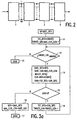
- Figure 2 shows diagrammatically a block diagram of a device for transmitting a digital audio signal as a bit stream, the bit stream comprising a minimal number of bits which yet enables the digital audio signal to be reconstructed in a receiver.
- a subband filter bank 1 receives the sampled and quantized digital audio signal and in known manner splits this into, for example, 64 subbands.
- Each of the subbands is divided into subframes, each comprising for example 24 symbol representations.
- a number of, for example, 3 subframes forms one frame.
- the subframes of each of the subbands are quantized into a given number of representation symbols, for example -2 15 - 2 15 symbols. This quantization is greater than that used for the quantization of the signal applied to the filter bank 1.
- the probabilities for each representation symbol are transmitted and both the encoder and the decoder define an identical variable-length coding table, for example a Huffman coding table, on the basis of these values.
- the representation symbols may first be arranged in groups, for example groups of 3 representation symbols, an individual Huffman code being assigned to each group, as set forth hereinbefore.
- the codes for each group, in the case of Huffman coding, or for each representation symbol are subsequently transmitted and in a receiver the decoder can derive the actual representation symbols from these codes.
- the total number of bits necessary for transmitting the (groups) of representation symbols and the information about the probabilities, which information is needed to generate the same (de)coding table in the encoder and the decoder, is constantly checked and compared with the number of bits necessary when for the representation symbols code words of a fixed length are selected. If a fixed-length coding requires a smaller number of bits than the variable-length coding, the first-mentioned coding is used. Such a situation can occur if there are few samples for a given number of representation symbols and the table specification consequently requires a comparatively large number of additional bits.
- variable-length coding unit 4 utilizes a Huffman coding wherein either merely the number of code words of each length is transmitted and/or the code words of the greatest code word length. This technique may be combined with reduction of the greatest code word length and testing whether this results in a reduction of the total number of bits required for transmitting the code table information and the actual codes which the representation symbols represent.
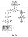
- Figure 3a, b is a flow chart showing the steps to be performed in order to realize this.
- a block 11 the total number of bits is counted and the target code word length (TARGET-LEN) is equalized to MAX-CUR-LEN - 1.
- a decision block 12 it is ascertained whether 2 TARGET-LEN > N DATA. If this is not the case, a further code word length reduction is not possible and the process is terminated in a block 13. If said requirement is met, the length of the code words having the greatest number of bits is reduced by one in a block 14 by means of a sub-process adjust-BITS, illustrated in Figure 3b.
- the adjust-BITS process is a variant of the process used in the JPEG standard in order to ensure that there is no code of a length greater than a predetermined length. This process is described in Appendix A of ISO-DIS 10918-1.
- a block 21 the MAX-CUR-LEN is set to I.
- the GAIN is determined, i.e. the number of bits prior to code word reduction is reduced to the number of bits after this reduction, i.e. TOT-BITS - CUR-BITS. If in a block 15 it appears that GAIN ⁇ 0, the process is terminated in blocks 16, 17 and, if this is not the case, the loop is traversed gain via a block 18.
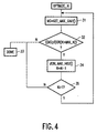
- Huffman coding When a Huffman coding is selected it can also be attempted to reduce the total number of bits required for the code table information by combining Huffman codes for different numbers of representation symbols. It is possible, for example, to code 3 representation symbols with a table for 5 representation symbols, which may less efficient but which enables only one instead of two coding information tables to be transmitted.
- Figure 4 is a flow chart for a process OPTIMIZE-N, which is suitable for this purpose.
- MG is equalized to GET-MAX-GAIN.
- the gain is determined which is obtained by the combination of Huffman codes for a number of levels and the next higher level, the combination yielding the highest gain in bits being selected.
- the invention is particularly suitable for frame-based coding of representation symbol sources, as occurring in audio and video coding systems, for example symbol sources, without memory and with similar probability density functions.
Claims (3)
- Codiertes Informationssignal, das ein Informationssignal darstellt, das zu Repräsentationssymbolen abgetastet und quantisiert wird, die daraufhin in Codeworte verschiedener Codewortlängen codiert werden, wobei Codeworte einer geringen Länge den Repräsentationssymbolen zugeordnet werden, die eine hohe Wahrscheinlichkeit des Auftritts haben und Codeworte einer größeren Länge Repräsentationssymbolen zugeordnet werden, deren Auftrittswahrscheinlichkeit gering ist, und zwar entsprechend einer vorbestimmten Codierungstechnik, dadurch gekennzeichnet, dass das codierte Informationssignal Information über die Länge des mit jedem möglichen Repräsentationssymbol assoziierten Codewortes aufweist, wobei die Information über die Länge jedes der Codeworte durch eine Anzahl Bit gegeben wird, die der Anzahl Bits entspricht, die notwendig sind zum Codieren der Länge des Codewortes mit der maximalen Länge.
- Signal nach Anspruch 1, wobei die Repräsentationssymbole mit Hilfe einer Huffman-Codierungstechnik codiert werden.
- Signal nach Anspruch 1 oder 2, dadurch gekennzeichnet, dass eine Entropie-Codierung angewandt wird zum Spezifizieren der Codewortlängen.
Priority Applications (1)
| Application Number | Priority Date | Filing Date | Title |
|---|---|---|---|
| EP03101752A EP1359755B1 (de) | 1996-12-20 | 1997-03-03 | Kodiertes Informationssignal |
Applications Claiming Priority (4)
| Application Number | Priority Date | Filing Date | Title |
|---|---|---|---|
| EP96203651 | 1996-12-20 | ||
| EP96203651 | 1996-12-20 | ||
| EP97904546A EP0826275B1 (de) | 1996-03-15 | 1997-03-03 | Verfahren und vorrichtung zur kodierung eines digitalen informationssignales |
| EP03101752A EP1359755B1 (de) | 1996-12-20 | 1997-03-03 | Kodiertes Informationssignal |
Related Parent Applications (1)
| Application Number | Title | Priority Date | Filing Date |
|---|---|---|---|
| EP97904546.5 Division | 1997-09-25 |
Publications (2)
| Publication Number | Publication Date |
|---|---|
| EP1359755A1 EP1359755A1 (de) | 2003-11-05 |
| EP1359755B1 true EP1359755B1 (de) | 2005-11-09 |
Family
ID=29217247
Family Applications (1)
| Application Number | Title | Priority Date | Filing Date |
|---|---|---|---|
| EP03101752A Expired - Lifetime EP1359755B1 (de) | 1996-12-20 | 1997-03-03 | Kodiertes Informationssignal |
Country Status (1)
| Country | Link |
|---|---|
| EP (1) | EP1359755B1 (de) |
Families Citing this family (1)
| Publication number | Priority date | Publication date | Assignee | Title |
|---|---|---|---|---|
| US7830921B2 (en) | 2005-07-11 | 2010-11-09 | Lg Electronics Inc. | Apparatus and method of encoding and decoding audio signal |
Family Cites Families (3)
| Publication number | Priority date | Publication date | Assignee | Title |
|---|---|---|---|---|
| FR2627337B1 (fr) * | 1988-02-17 | 1990-06-08 | Thomson Csf | Procede de codage et procede de decodage a longueur variable, dispositif de codage et dispositif de decodage pour la mise en oeuvre de ce proced |
| US5045852A (en) * | 1990-03-30 | 1991-09-03 | International Business Machines Corporation | Dynamic model selection during data compression |
| JP2697479B2 (ja) * | 1992-04-17 | 1998-01-14 | 国際電信電話株式会社 | 可逆可変長符号化方式 |
-
1997
- 1997-03-03 EP EP03101752A patent/EP1359755B1/de not_active Expired - Lifetime
Also Published As
| Publication number | Publication date |
|---|---|
| EP1359755A1 (de) | 2003-11-05 |
Similar Documents
| Publication | Publication Date | Title |
|---|---|---|
| EP0826275B1 (de) | Verfahren und vorrichtung zur kodierung eines digitalen informationssignales | |
| EP2267698B1 (de) | Entropische Kodierung mittels Anpassung des Kodierungsmodus zwischen Niveau- und Lauflängenniveau-Modus | |
| US5045852A (en) | Dynamic model selection during data compression | |
| EP0405572B1 (de) | Sprachcodierungs-/-decodierungssystem | |
| KR101226566B1 (ko) | 심볼을 인코딩하기 위한 방법, 심볼을 디코딩하기 위한 방법, 송신기로부터 수신기로 심볼을 전송하기 위한 방법, 인코더, 디코더 및 송신기로부터 수신기로 심볼을 전송하기 위한 시스템 | |
| EP0616471B1 (de) | Kodierung von digitalen Signalen | |
| US5463699A (en) | Data compression | |
| KR102400514B1 (ko) | 디지털 데이터 압축을 위한 방법 및 디바이스 | |
| JP3990464B2 (ja) | ディジタルビデオ信号プロセッサのためのデータ効率のよい量子化テーブル | |
| WO2004112400A1 (en) | Coding apparatus, coding method, and codebook | |
| EP1472793B1 (de) | Datenkomprimierung und dekomprimierung eines digitalen informationssignals | |
| EP1359755B1 (de) | Kodiertes Informationssignal | |
| US6839674B1 (en) | Method and apparatus for spectral exponent reshaping in a transform coder for high quality audio | |
| JPH0728500A (ja) | 音声符号器及び音声復号器 |
Legal Events
| Date | Code | Title | Description |
|---|---|---|---|
| PUAI | Public reference made under article 153(3) epc to a published international application that has entered the european phase |
Free format text: ORIGINAL CODE: 0009012 |
|
| AC | Divisional application: reference to earlier application |
Ref document number: 0826275 Country of ref document: EP Kind code of ref document: P |
|
| AK | Designated contracting states |
Kind code of ref document: A1 Designated state(s): DE FR GB IT |
|
| 17P | Request for examination filed |
Effective date: 20040506 |
|
| AKX | Designation fees paid |
Designated state(s): DE FR GB IT |
|
| GRAP | Despatch of communication of intention to grant a patent |
Free format text: ORIGINAL CODE: EPIDOSNIGR1 |
|
| GRAS | Grant fee paid |
Free format text: ORIGINAL CODE: EPIDOSNIGR3 |
|
| GRAA | (expected) grant |
Free format text: ORIGINAL CODE: 0009210 |
|
| AC | Divisional application: reference to earlier application |
Ref document number: 0826275 Country of ref document: EP Kind code of ref document: P |
|
| AK | Designated contracting states |
Kind code of ref document: B1 Designated state(s): DE FR GB IT |
|
| PG25 | Lapsed in a contracting state [announced via postgrant information from national office to epo] |
Ref country code: IT Free format text: LAPSE BECAUSE OF FAILURE TO SUBMIT A TRANSLATION OF THE DESCRIPTION OR TO PAY THE FEE WITHIN THE PRESCRIBED TIME-LIMIT;WARNING: LAPSES OF ITALIAN PATENTS WITH EFFECTIVE DATE BEFORE 2007 MAY HAVE OCCURRED AT ANY TIME BEFORE 2007. THE CORRECT EFFECTIVE DATE MAY BE DIFFERENT FROM THE ONE RECORDED. Effective date: 20051109 |
|
| REG | Reference to a national code |
Ref country code: GB Ref legal event code: FG4D |
|
| REF | Corresponds to: |
Ref document number: 69734613 Country of ref document: DE Date of ref document: 20051215 Kind code of ref document: P |
|
| PGFP | Annual fee paid to national office [announced via postgrant information from national office to epo] |
Ref country code: GB Payment date: 20060328 Year of fee payment: 10 |
|
| PGFP | Annual fee paid to national office [announced via postgrant information from national office to epo] |
Ref country code: FR Payment date: 20060330 Year of fee payment: 10 |
|
| PGFP | Annual fee paid to national office [announced via postgrant information from national office to epo] |
Ref country code: DE Payment date: 20060522 Year of fee payment: 10 |
|
| ET | Fr: translation filed | ||
| PLBE | No opposition filed within time limit |
Free format text: ORIGINAL CODE: 0009261 |
|
| STAA | Information on the status of an ep patent application or granted ep patent |
Free format text: STATUS: NO OPPOSITION FILED WITHIN TIME LIMIT |
|
| 26N | No opposition filed |
Effective date: 20060810 |
|
| GBPC | Gb: european patent ceased through non-payment of renewal fee |
Effective date: 20070303 |
|
| REG | Reference to a national code |
Ref country code: FR Ref legal event code: ST Effective date: 20071130 |
|
| PG25 | Lapsed in a contracting state [announced via postgrant information from national office to epo] |
Ref country code: DE Free format text: LAPSE BECAUSE OF NON-PAYMENT OF DUE FEES Effective date: 20071002 |
|
| PG25 | Lapsed in a contracting state [announced via postgrant information from national office to epo] |
Ref country code: GB Free format text: LAPSE BECAUSE OF NON-PAYMENT OF DUE FEES Effective date: 20070303 |
|
| PG25 | Lapsed in a contracting state [announced via postgrant information from national office to epo] |
Ref country code: FR Free format text: LAPSE BECAUSE OF NON-PAYMENT OF DUE FEES Effective date: 20070402 |