EP1359633A1 - Galvanic element with thin electrodes - Google Patents
Galvanic element with thin electrodes Download PDFInfo
- Publication number
- EP1359633A1 EP1359633A1 EP03008511A EP03008511A EP1359633A1 EP 1359633 A1 EP1359633 A1 EP 1359633A1 EP 03008511 A EP03008511 A EP 03008511A EP 03008511 A EP03008511 A EP 03008511A EP 1359633 A1 EP1359633 A1 EP 1359633A1
- Authority
- EP
- European Patent Office
- Prior art keywords
- plastic
- metallization
- galvanic element
- element according
- electrodes
- Prior art date
- Legal status (The legal status is an assumption and is not a legal conclusion. Google has not performed a legal analysis and makes no representation as to the accuracy of the status listed.)
- Granted
Links
- 239000011888 foil Substances 0.000 claims abstract description 22
- 239000004033 plastic Substances 0.000 claims abstract description 18
- 229920003023 plastic Polymers 0.000 claims abstract description 18
- 238000001465 metallisation Methods 0.000 claims description 32
- 239000002985 plastic film Substances 0.000 claims description 21
- 229920006255 plastic film Polymers 0.000 claims description 21
- 239000002131 composite material Substances 0.000 claims description 20
- 229910052751 metal Inorganic materials 0.000 claims description 12
- 239000002184 metal Substances 0.000 claims description 12
- 239000004020 conductor Substances 0.000 claims description 10
- 238000000034 method Methods 0.000 claims description 6
- 238000007789 sealing Methods 0.000 claims description 6
- 239000002998 adhesive polymer Substances 0.000 claims 1
- 210000004027 cell Anatomy 0.000 description 18
- 229910052782 aluminium Inorganic materials 0.000 description 10
- XAGFODPZIPBFFR-UHFFFAOYSA-N aluminium Chemical compound [Al] XAGFODPZIPBFFR-UHFFFAOYSA-N 0.000 description 10
- 229910052744 lithium Inorganic materials 0.000 description 8
- 239000002905 metal composite material Substances 0.000 description 7
- WHXSMMKQMYFTQS-UHFFFAOYSA-N Lithium Chemical group [Li] WHXSMMKQMYFTQS-UHFFFAOYSA-N 0.000 description 6
- -1 polypropylene Polymers 0.000 description 5
- 239000004743 Polypropylene Substances 0.000 description 4
- 229920001155 polypropylene Polymers 0.000 description 4
- RYGMFSIKBFXOCR-UHFFFAOYSA-N Copper Chemical class [Cu] RYGMFSIKBFXOCR-UHFFFAOYSA-N 0.000 description 3
- 230000004888 barrier function Effects 0.000 description 3
- 239000003792 electrolyte Substances 0.000 description 3
- PXHVJJICTQNCMI-UHFFFAOYSA-N nickel Substances [Ni] PXHVJJICTQNCMI-UHFFFAOYSA-N 0.000 description 3
- 229920000642 polymer Polymers 0.000 description 3
- CSCPPACGZOOCGX-UHFFFAOYSA-N Acetone Chemical compound CC(C)=O CSCPPACGZOOCGX-UHFFFAOYSA-N 0.000 description 2
- 239000004952 Polyamide Substances 0.000 description 2
- 239000011149 active material Substances 0.000 description 2
- 230000015572 biosynthetic process Effects 0.000 description 2
- 229920001577 copolymer Polymers 0.000 description 2
- 229910052802 copper Inorganic materials 0.000 description 2
- 239000010949 copper Substances 0.000 description 2
- 238000009792 diffusion process Methods 0.000 description 2
- 238000005516 engineering process Methods 0.000 description 2
- 239000000463 material Substances 0.000 description 2
- 229920002647 polyamide Polymers 0.000 description 2
- 238000001771 vacuum deposition Methods 0.000 description 2
- IEPQGNKWXNDSOS-UHFFFAOYSA-N 1,1,2,3,3,3-hexafluoroprop-1-ene dihydrofluoride Chemical group FC(C(F)=C(F)F)(F)F.F.F IEPQGNKWXNDSOS-UHFFFAOYSA-N 0.000 description 1
- 229910000851 Alloy steel Inorganic materials 0.000 description 1
- OKTJSMMVPCPJKN-UHFFFAOYSA-N Carbon Chemical compound [C] OKTJSMMVPCPJKN-UHFFFAOYSA-N 0.000 description 1
- 239000004831 Hot glue Substances 0.000 description 1
- 229910012851 LiCoO 2 Inorganic materials 0.000 description 1
- 239000002033 PVDF binder Substances 0.000 description 1
- 239000004698 Polyethylene Substances 0.000 description 1
- 239000000654 additive Substances 0.000 description 1
- 229910045601 alloy Inorganic materials 0.000 description 1
- 239000000956 alloy Substances 0.000 description 1
- 230000009286 beneficial effect Effects 0.000 description 1
- 239000011230 binding agent Substances 0.000 description 1
- 210000003850 cellular structure Anatomy 0.000 description 1
- 238000003486 chemical etching Methods 0.000 description 1
- 239000011889 copper foil Substances 0.000 description 1
- 238000005260 corrosion Methods 0.000 description 1
- 230000007797 corrosion Effects 0.000 description 1
- 238000011049 filling Methods 0.000 description 1
- 229910002804 graphite Inorganic materials 0.000 description 1
- 239000010439 graphite Substances 0.000 description 1
- 238000009830 intercalation Methods 0.000 description 1
- 150000002500 ions Chemical class 0.000 description 1
- 238000003475 lamination Methods 0.000 description 1
- 238000000608 laser ablation Methods 0.000 description 1
- 229910052759 nickel Inorganic materials 0.000 description 1
- 239000005486 organic electrolyte Substances 0.000 description 1
- 238000002161 passivation Methods 0.000 description 1
- 238000000206 photolithography Methods 0.000 description 1
- XNGIFLGASWRNHJ-UHFFFAOYSA-L phthalate(2-) Chemical compound [O-]C(=O)C1=CC=CC=C1C([O-])=O XNGIFLGASWRNHJ-UHFFFAOYSA-L 0.000 description 1
- 238000001020 plasma etching Methods 0.000 description 1
- 239000004014 plasticizer Substances 0.000 description 1
- 229920000573 polyethylene Polymers 0.000 description 1
- 229920000131 polyvinylidene Polymers 0.000 description 1
- 229920002981 polyvinylidene fluoride Polymers 0.000 description 1
- 238000007639 printing Methods 0.000 description 1
- 238000007493 shaping process Methods 0.000 description 1
- 239000003381 stabilizer Substances 0.000 description 1
- 229910001220 stainless steel Inorganic materials 0.000 description 1
- 239000010935 stainless steel Substances 0.000 description 1
- 229910001256 stainless steel alloy Inorganic materials 0.000 description 1
- 239000010959 steel Substances 0.000 description 1
- 230000007704 transition Effects 0.000 description 1
- XLYOFNOQVPJJNP-UHFFFAOYSA-N water Chemical compound O XLYOFNOQVPJJNP-UHFFFAOYSA-N 0.000 description 1
- 238000003466 welding Methods 0.000 description 1
Images


Classifications
-
- H—ELECTRICITY
- H01—ELECTRIC ELEMENTS
- H01M—PROCESSES OR MEANS, e.g. BATTERIES, FOR THE DIRECT CONVERSION OF CHEMICAL ENERGY INTO ELECTRICAL ENERGY
- H01M10/00—Secondary cells; Manufacture thereof
- H01M10/04—Construction or manufacture in general
- H01M10/0436—Small-sized flat cells or batteries for portable equipment
-
- H—ELECTRICITY
- H01—ELECTRIC ELEMENTS
- H01M—PROCESSES OR MEANS, e.g. BATTERIES, FOR THE DIRECT CONVERSION OF CHEMICAL ENERGY INTO ELECTRICAL ENERGY
- H01M10/00—Secondary cells; Manufacture thereof
- H01M10/05—Accumulators with non-aqueous electrolyte
- H01M10/058—Construction or manufacture
-
- H—ELECTRICITY
- H01—ELECTRIC ELEMENTS
- H01M—PROCESSES OR MEANS, e.g. BATTERIES, FOR THE DIRECT CONVERSION OF CHEMICAL ENERGY INTO ELECTRICAL ENERGY
- H01M6/00—Primary cells; Manufacture thereof
- H01M6/40—Printed batteries, e.g. thin film batteries
-
- H—ELECTRICITY
- H01—ELECTRIC ELEMENTS
- H01M—PROCESSES OR MEANS, e.g. BATTERIES, FOR THE DIRECT CONVERSION OF CHEMICAL ENERGY INTO ELECTRICAL ENERGY
- H01M10/00—Secondary cells; Manufacture thereof
- H01M10/42—Methods or arrangements for servicing or maintenance of secondary cells or secondary half-cells
- H01M10/425—Structural combination with electronic components, e.g. electronic circuits integrated to the outside of the casing
-
- H—ELECTRICITY
- H01—ELECTRIC ELEMENTS
- H01M—PROCESSES OR MEANS, e.g. BATTERIES, FOR THE DIRECT CONVERSION OF CHEMICAL ENERGY INTO ELECTRICAL ENERGY
- H01M50/00—Constructional details or processes of manufacture of the non-active parts of electrochemical cells other than fuel cells, e.g. hybrid cells
- H01M50/10—Primary casings; Jackets or wrappings
- H01M50/116—Primary casings; Jackets or wrappings characterised by the material
- H01M50/117—Inorganic material
- H01M50/119—Metals
-
- H—ELECTRICITY
- H01—ELECTRIC ELEMENTS
- H01M—PROCESSES OR MEANS, e.g. BATTERIES, FOR THE DIRECT CONVERSION OF CHEMICAL ENERGY INTO ELECTRICAL ENERGY
- H01M50/00—Constructional details or processes of manufacture of the non-active parts of electrochemical cells other than fuel cells, e.g. hybrid cells
- H01M50/10—Primary casings; Jackets or wrappings
- H01M50/116—Primary casings; Jackets or wrappings characterised by the material
- H01M50/121—Organic material
-
- H—ELECTRICITY
- H01—ELECTRIC ELEMENTS
- H01M—PROCESSES OR MEANS, e.g. BATTERIES, FOR THE DIRECT CONVERSION OF CHEMICAL ENERGY INTO ELECTRICAL ENERGY
- H01M50/00—Constructional details or processes of manufacture of the non-active parts of electrochemical cells other than fuel cells, e.g. hybrid cells
- H01M50/10—Primary casings; Jackets or wrappings
- H01M50/116—Primary casings; Jackets or wrappings characterised by the material
- H01M50/124—Primary casings; Jackets or wrappings characterised by the material having a layered structure
- H01M50/126—Primary casings; Jackets or wrappings characterised by the material having a layered structure comprising three or more layers
-
- H—ELECTRICITY
- H01—ELECTRIC ELEMENTS
- H01M—PROCESSES OR MEANS, e.g. BATTERIES, FOR THE DIRECT CONVERSION OF CHEMICAL ENERGY INTO ELECTRICAL ENERGY
- H01M50/00—Constructional details or processes of manufacture of the non-active parts of electrochemical cells other than fuel cells, e.g. hybrid cells
- H01M50/10—Primary casings; Jackets or wrappings
- H01M50/131—Primary casings; Jackets or wrappings characterised by physical properties, e.g. gas permeability, size or heat resistance
- H01M50/133—Thickness
-
- H—ELECTRICITY
- H01—ELECTRIC ELEMENTS
- H01M—PROCESSES OR MEANS, e.g. BATTERIES, FOR THE DIRECT CONVERSION OF CHEMICAL ENERGY INTO ELECTRICAL ENERGY
- H01M50/00—Constructional details or processes of manufacture of the non-active parts of electrochemical cells other than fuel cells, e.g. hybrid cells
- H01M50/10—Primary casings; Jackets or wrappings
- H01M50/172—Arrangements of electric connectors penetrating the casing
- H01M50/174—Arrangements of electric connectors penetrating the casing adapted for the shape of the cells
- H01M50/176—Arrangements of electric connectors penetrating the casing adapted for the shape of the cells for prismatic or rectangular cells
-
- H—ELECTRICITY
- H01—ELECTRIC ELEMENTS
- H01M—PROCESSES OR MEANS, e.g. BATTERIES, FOR THE DIRECT CONVERSION OF CHEMICAL ENERGY INTO ELECTRICAL ENERGY
- H01M50/00—Constructional details or processes of manufacture of the non-active parts of electrochemical cells other than fuel cells, e.g. hybrid cells
- H01M50/50—Current conducting connections for cells or batteries
- H01M50/543—Terminals
- H01M50/547—Terminals characterised by the disposition of the terminals on the cells
- H01M50/55—Terminals characterised by the disposition of the terminals on the cells on the same side of the cell
-
- H—ELECTRICITY
- H01—ELECTRIC ELEMENTS
- H01M—PROCESSES OR MEANS, e.g. BATTERIES, FOR THE DIRECT CONVERSION OF CHEMICAL ENERGY INTO ELECTRICAL ENERGY
- H01M50/00—Constructional details or processes of manufacture of the non-active parts of electrochemical cells other than fuel cells, e.g. hybrid cells
- H01M50/50—Current conducting connections for cells or batteries
- H01M50/543—Terminals
- H01M50/552—Terminals characterised by their shape
- H01M50/553—Terminals adapted for prismatic, pouch or rectangular cells
-
- H—ELECTRICITY
- H01—ELECTRIC ELEMENTS
- H01M—PROCESSES OR MEANS, e.g. BATTERIES, FOR THE DIRECT CONVERSION OF CHEMICAL ENERGY INTO ELECTRICAL ENERGY
- H01M50/00—Constructional details or processes of manufacture of the non-active parts of electrochemical cells other than fuel cells, e.g. hybrid cells
- H01M50/50—Current conducting connections for cells or batteries
- H01M50/543—Terminals
- H01M50/562—Terminals characterised by the material
-
- H—ELECTRICITY
- H01—ELECTRIC ELEMENTS
- H01M—PROCESSES OR MEANS, e.g. BATTERIES, FOR THE DIRECT CONVERSION OF CHEMICAL ENERGY INTO ELECTRICAL ENERGY
- H01M10/00—Secondary cells; Manufacture thereof
- H01M10/05—Accumulators with non-aqueous electrolyte
- H01M10/052—Li-accumulators
-
- Y—GENERAL TAGGING OF NEW TECHNOLOGICAL DEVELOPMENTS; GENERAL TAGGING OF CROSS-SECTIONAL TECHNOLOGIES SPANNING OVER SEVERAL SECTIONS OF THE IPC; TECHNICAL SUBJECTS COVERED BY FORMER USPC CROSS-REFERENCE ART COLLECTIONS [XRACs] AND DIGESTS
- Y02—TECHNOLOGIES OR APPLICATIONS FOR MITIGATION OR ADAPTATION AGAINST CLIMATE CHANGE
- Y02E—REDUCTION OF GREENHOUSE GAS [GHG] EMISSIONS, RELATED TO ENERGY GENERATION, TRANSMISSION OR DISTRIBUTION
- Y02E60/00—Enabling technologies; Technologies with a potential or indirect contribution to GHG emissions mitigation
- Y02E60/10—Energy storage using batteries
-
- Y—GENERAL TAGGING OF NEW TECHNOLOGICAL DEVELOPMENTS; GENERAL TAGGING OF CROSS-SECTIONAL TECHNOLOGIES SPANNING OVER SEVERAL SECTIONS OF THE IPC; TECHNICAL SUBJECTS COVERED BY FORMER USPC CROSS-REFERENCE ART COLLECTIONS [XRACs] AND DIGESTS
- Y02—TECHNOLOGIES OR APPLICATIONS FOR MITIGATION OR ADAPTATION AGAINST CLIMATE CHANGE
- Y02P—CLIMATE CHANGE MITIGATION TECHNOLOGIES IN THE PRODUCTION OR PROCESSING OF GOODS
- Y02P70/00—Climate change mitigation technologies in the production process for final industrial or consumer products
- Y02P70/50—Manufacturing or production processes characterised by the final manufactured product
Definitions
- the invention relates to a galvanic element with the features of the preamble of claim 1.
- the galvanic element can have thin electrodes in a housing made from each other sealed plastic films is formed.
- Galvanic elements are known in various designs. In most cases, they have a mechanically stable housing and, for example, the shape of round, button or prismatic cells in which positive and negative electrodes as well as a separator and the electrolyte are arranged.
- the housings of galvanic elements with alkaline electrolytes such as Zn / MnO 2 or Ni / MeH have a housing made of steel or stainless steel alloy, the outer surfaces of which are usually nickel-plated for better contact.
- the housings are due to the higher electrode potential of up to 4.2 volts made of stainless steel or aluminum to avoid corrosion, which is used for passivation of the metal surfaces and to form higher transition contact resistances leads.
- the contact pressure is sufficient for low load requirements the electrodes on the conductive container mostly as contact out. As far as higher demands are placed on the current carrying capacity additional contacting, as is the case with lithium cells in particular in the form of metallic collectors within the electrodes and a connection of these collectors by welding arrester lugs to the housing necessary.
- a film housing In addition to galvanic elements with mechanically very stable housings are also known elements that have film housing. Such a film housing are used, for example, in so-called lithium / polymer or lithium / ion cells used. These polymer cells have a Housing made of a composite film, for example made of polyamide / aluminum / polypropylene consists. By using these foils high flexibility of design, low weight and high Security achieved. The aluminum layer in these composite foils serves thereby as a gas barrier.
- Galvanic elements of this type generally contain a cell stack, which is made up of many individual cells or individual elements is.
- the single element is a laminate that consists of an arrester and an active electrode film and separator is generated.
- Such laminates from firmly connected Individual parts are, for example, so-called bicells with the possible sequences negative electrode / separator / positive Electrode / separator / negative electrode or positive electrode / separator / negative Electrode / separator / positive electrode made.
- US Pat. No. 5,460,904 is a process for producing such a lithium / ion battery refer to.
- This procedure will be active Materials and additives, such as conductivity improvers if necessary in the electrodes or stabilizers in the separator, a special one Copolymer, polyvinylidene difluoride-hexafluoropropylene (PVDF-HFP) as well Portions of a plasticizer, typically dibuthyl phthalate (DBP), after the addition of acetone to dissolve the copolymer, mixed intensively and pulled out to a film.
- the electrode foils thus formed and separator foils are made in several lamination processes Processed bicells.
- Several bizelles are stacked up in a stack. The stack is made from, for example, after placing it in a container thermoformed aluminum composite foil, filling with electrolyte, sealing with a lid, formation and end closure to one finished Battery processed.
- the individual electrodes have lead frames in the form of a Copper foil for the negative electrode and in the form of aluminum for the positive electrode, which each have conductor tabs. Over the drain tabs several electrodes are connected in parallel and from the Composite for external contact through the housing. Sufficient contacting of the individual electrodes is therefore essential many components necessary. It also seals the housing around these lead flags.
- the invention has for its object a galvanic element to create the kind mentioned above, the simple and inexpensive can be produced, and in particular the contacting between the electrode and the outer conductor is improved.
- the active cell components are sealed between two Arranged plastic films, these plastic films also composite films with an inner metal layer, for example an aluminum layer, could be.
- the metallization on the one facing the electrode Page can be used as a surface pattern or with breaks Metallization be formed. In the area of leading to the outside The metallization can be reinforced by applying a conductor additional metal layer or by applying another metal foil. It is also possible to use the two that form the cell housing Do not seal plastic films directly to one another, but between them to use a sealing frame for the two foils as an aid.
- one of the plastic films or in particular the Plastic metal composite films preformed by a deep-drawing process become. It is particularly useful to the galvanic housing Form elements from two sealed plastic films. These are metallized on their side facing the inside of the cell in such a way that the metallization on the one hand the electrical contact with the Electrodes and on the other hand the outer contact tabs of the electrodes of the galvanic element.
- FIG. 4 there is a galvanic according to the invention Element made of a first plastic film 1, partially with a Metallization 2 is provided, and a second plastic film 7, the is also provided with a metallization 8.
- the ones that make up the case Films 1 and 7 can be plastic films.
- Such a composite film exists, for example from an outer polyamide layer 1 a, 7 a, a middle Aluminum layer 1b, 7b and an inner polypropylene layer 1c, 7c, which in each case the metallization adapted to the shape of the electrode wearing.
- the films are vacuum coated partially metallized on the polypropylene side.
- the area of metallization is in particular somewhat smaller or practically the same Size of electrodes 5 and 6.
- the positive electrode 5 can be, for example, an MnO 2 or LiCoO 2 electrode or a Li x MnO 2 electrode.
- the negative electrode 6 can consist of lithium metal, a lithium metal alloy, or be a lithium intercalating graphite electrode.
- the separator 4 is, for example, a polypropylene film, polyethylene film or a nonwoven made from these materials.
- the composite films 1 and 7 are under Vacuum in the non-metallized sealing zone 10 and above that Implementation of the contacts thermally sealed. Alternatively, they will with each other by means of a hot-melt adhesive designed as a sealing frame 11 glued.
- FIG. 1 shows the cross section through such a finished cell 3 or 9, which are connected to the metallization 2 or 8 stand, form the outer current arrester of the cell. This is from Figure 2 seen the same cell in a partially sectioned top view shows.
- the embodiment of a galvanic element according to FIG. 3 differs essentially from the embodiment according to FIG in that a folded electrode package is used here. This consists of anode 5 and cathode 6 with an intermediate separator 4th
- these electrodes for example consist of the active materials and PVDF as a binder, these are laminated directly onto the metallized composite films as a carrier can.
- electrodes manufactured in this way in an arrangement according to Figure 3 in which instead of a stack of electrodes, a folded Electrode is used, it is possible to use the cell too load higher currents.
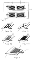
- the metallization of the foils which takes place in certain areas, can be extensive or can also be executed in the form of a pattern, as is the case with the figures 7a to 7d can be seen.
- Figure 6 shows the arrangement of the Metallizations on a plastic composite tape 13. The Areas 2 metallized with aluminum and areas 8 with copper.
- At least one of the plastic films or plastic metal composite films at the same time the carrier of conductor tracks 12 for other electronic components.
- this will Metallization simultaneously with the metallization of the collector surface in the Cell housing applied.
- the collector areas 2 and 8 and the conductor tracks 12 can by vacuum coating, by electroless or galvanic metal deposition or by printing with conductive Pastes are applied.
- Electroless or galvanic metal deposition on the collector surfaces 2 and 8 and the conductor tracks 12 can over mask technology directly structured.
- the metallization each take place over the entire area.
- the respective structure is by means of Laser ablation or conventional photolithography combined manufactured with chemical etching technology or plasma etching.
- the inside of the composite film Arranged metal layer can be made of aluminum, copper or nickel Vapor or gas diffusion barrier exist. It can be beneficial in particular the thickness of the conductor tabs 3 and 9 by an additional one Metallization step increase or these areas with a to reinforce additional metal foil.
- the plastic film or plastic metal composite film has a thickness of 5 to 400 microns, in particular a thickness of 10 to 150 microns.
- the metallization on this composite film applied, has a thickness of 0.02 to 30 microns, preferably a thickness of approximately 0.1 to 5 ⁇ m.
Landscapes
- Chemical & Material Sciences (AREA)
- Chemical Kinetics & Catalysis (AREA)
- Electrochemistry (AREA)
- General Chemical & Material Sciences (AREA)
- Engineering & Computer Science (AREA)
- Manufacturing & Machinery (AREA)
- Inorganic Chemistry (AREA)
- Microelectronics & Electronic Packaging (AREA)
- Sealing Battery Cases Or Jackets (AREA)
- Connection Of Batteries Or Terminals (AREA)
- Primary Cells (AREA)
- Secondary Cells (AREA)
- Thermistors And Varistors (AREA)
- Piezo-Electric Or Mechanical Vibrators, Or Delay Or Filter Circuits (AREA)
Abstract
Description
Gegenstand der Erfindung ist ein galvanisches Element mit den Merkmalen
des Oberbegriffs des Anspruchs 1. Das galvanische Element
kann dünne Elektroden aufweisen in einem Gehäuse, das aus miteinander
versiegelten Kunststofffolien gebildet ist.The invention relates to a galvanic element with the features
of the preamble of
Galvanische Elemente sind in verschiedenen Bauformen bekannt. Sie besitzen in den meisten Fällen ein mechanisch stabiles Gehäuse und beispielsweise die Form von Rund-, Knopf- oder prismatischen Zellen, in denen positive und negative Elektrode sowie ein Separator und der Elektrolyt angeordnet sind. Die Gehäuse von galvanischen Elementen mit alkalischem Elektrolyten wie z.B. Zn/MnO2 oder Ni/MeH besitzen ein Gehäuse aus Stahl oder Edelstahllegierung, dessen äußere Oberflächen zur besseren Kontaktierung meist vernickelt sind.Galvanic elements are known in various designs. In most cases, they have a mechanically stable housing and, for example, the shape of round, button or prismatic cells in which positive and negative electrodes as well as a separator and the electrolyte are arranged. The housings of galvanic elements with alkaline electrolytes such as Zn / MnO 2 or Ni / MeH have a housing made of steel or stainless steel alloy, the outer surfaces of which are usually nickel-plated for better contact.
Bei primären und sekundären Lithiumzellen bestehen die Gehäuse aufgrund des höheren Elektrodenpotentials von bis zu 4,2 Volt aus Edelstahl oder Aluminium, um Korrosion zu vermeiden, die zur Passivierung der Metalloberflächen und zur Bildung höherer Übergangskontaktwiderstände führt.With primary and secondary lithium cells, the housings are due to the higher electrode potential of up to 4.2 volts made of stainless steel or aluminum to avoid corrosion, which is used for passivation of the metal surfaces and to form higher transition contact resistances leads.
Bei geringen Anforderungen an die Belastbarkeit reicht der Anpressdruck der Elektroden an den leitfähigen Behälter als Kontaktierung meist aus. Soweit höhere Anforderungen an die Strombelastbarkeit gestellt werden, wie insbesondere bei Lithiumzellen, ist eine zusätzliche Kontaktierung in Form von metallischen Kollektoren innerhalb der Elektroden und eine Anbindung dieser Kollektoren durch Anschweißen von Ableiterfahnen an das Gehäuse notwendig.The contact pressure is sufficient for low load requirements the electrodes on the conductive container mostly as contact out. As far as higher demands are placed on the current carrying capacity additional contacting, as is the case with lithium cells in particular in the form of metallic collectors within the electrodes and a connection of these collectors by welding arrester lugs to the housing necessary.
Neben galvanischen Elementen mit mechanisch sehr stabilen Gehäusen sind auch Elemente bekannt, die Foliengehäuse besitzen. Derartige Foliengehäuse werden beispielsweise bei sogenannten Lithium/Polymer- bzw. Lithium/Ionen-Zellen verwendet. Diese Polymerzellen besitzen ein Gehäuse aus einer Verbundfolie, die beispielsweise aus Polyamid/Aluminium/Polypropylen besteht. Durch die Verwendung dieser Folien wird eine hohe Flexibilität des Designs, ein niedriges Gewicht und eine hohe Sicherheit erreicht. Die Aluminiumschicht in diesen Verbundfolien dient dabei als Gassperre.In addition to galvanic elements with mechanically very stable housings are also known elements that have film housing. Such a film housing are used, for example, in so-called lithium / polymer or lithium / ion cells used. These polymer cells have a Housing made of a composite film, for example made of polyamide / aluminum / polypropylene consists. By using these foils high flexibility of design, low weight and high Security achieved. The aluminum layer in these composite foils serves thereby as a gas barrier.
Der Nachteil solcher Verbundfolien liegt darin, dass die Folie im Gegensatz zu einem metallischen Gehäuse keine elektrische Leitfähigkeit besitzt. Deswegen müssen an die Ableitergerüste der Elektroden Ableitfahnen angeschweißt und nach außen geführt werdenThe disadvantage of such composite films is that the film is in contrast has no electrical conductivity to a metallic housing. For this reason, lead tabs must be attached to the lead frames of the electrodes welded on and led outside
Galvanische Elemente dieser Art enthalten im Allgemeinen einen Zellenstapel, der aus vielen Einzelzellen bzw. Einzelelementen aufgebaut ist. Das Einzelelement ist ein Laminat, das aus Ableiter, aktivem Elektrodenfilm und Separator erzeugt wird. Derartige Laminate aus fest verbundenen Einzelteilen werden beispielsweise als sogenannte Bizellen mit den möglichen Sequenzen negative Elektrode/Separator/positive Elektrode/Separator/negative Elektrode oder positive Elektrode/Separator/negative Elektrode/Separator/positive Elektrode hergestellt.Galvanic elements of this type generally contain a cell stack, which is made up of many individual cells or individual elements is. The single element is a laminate that consists of an arrester and an active electrode film and separator is generated. Such laminates from firmly connected Individual parts are, for example, so-called bicells with the possible sequences negative electrode / separator / positive Electrode / separator / negative electrode or positive electrode / separator / negative Electrode / separator / positive electrode made.
Der US-PS 5,460,904 ist ein Verfahren zur Herstellung von solchen Lithium/lonenbatterie zu entnehmen. Bei diesem Verfahren werden aktive Materialien und Zusätze, wie gegebenenfalls Leitfähigkeitsverbesserer in den Elektroden oder Stabilisatoren im Separator, ein spezielles Copolymer, Polyvinylidendifluorid-Hexafluorpropylen (PVDF-HFP) sowie Anteile eines Weichmachers, typischerweise Dibuthylphthalat (DBP), nach Hinzugabe von Aceton zum Lösen des Copolymers intensiv gemischt und zu einer Folie ausgezogen. Die so gebildeten Elektrodenfolien und Separatorfolien werden in mehreren Laminationsprozessen zu Bizellen verarbeitet. Mehrere Bizellen werden zu einem Stapel aufgeschichtet. Der Stapel wird nach Einlegen in einen Behälter aus beispielsweise tiefgezogener Aluminiumverbundfolie, Befüllen mit Elektrolyt, Versiegeln mit einem Deckel, Formation und Endverschluss zu einer fertigen Batterie verarbeitet.US Pat. No. 5,460,904 is a process for producing such a lithium / ion battery refer to. This procedure will be active Materials and additives, such as conductivity improvers if necessary in the electrodes or stabilizers in the separator, a special one Copolymer, polyvinylidene difluoride-hexafluoropropylene (PVDF-HFP) as well Portions of a plasticizer, typically dibuthyl phthalate (DBP), after the addition of acetone to dissolve the copolymer, mixed intensively and pulled out to a film. The electrode foils thus formed and separator foils are made in several lamination processes Processed bicells. Several bizelles are stacked up in a stack. The stack is made from, for example, after placing it in a container thermoformed aluminum composite foil, filling with electrolyte, sealing with a lid, formation and end closure to one finished Battery processed.
Die einzelnen Elektroden besitzen dabei Ableitgerüste in Form einer Kupferfolie für die negative Elektrode und in Form von Aluminium für die positive Elektrode, die jeweils Ableiterfahnen besitzen. Über die Ableiterfahnen werden mehrere Elektroden parallel geschaltet und aus dem Verbund zur äußeren Kontaktierung durch das Gehäuse durchgeführt. Zur ausreichenden Kontaktierung der einzelnen Elektroden sind daher viele Komponenten notwendig. Außerdem ist die Abdichtung des Gehäuses um diese Ableitfahnen herum aufwendig.The individual electrodes have lead frames in the form of a Copper foil for the negative electrode and in the form of aluminum for the positive electrode, which each have conductor tabs. Over the drain tabs several electrodes are connected in parallel and from the Composite for external contact through the housing. Sufficient contacting of the individual electrodes is therefore essential many components necessary. It also seals the housing around these lead flags.
Der Erfindung liegt die Aufgabe zugrunde, ein galvanisches Element der eingangs genannten Art zu schaffen, das einfach und kostengünstig hergestellt werden kann, und bei dem insbesondere die Kontaktierung zwischen Elektrode und äußerem Ableiter verbessert ist. The invention has for its object a galvanic element to create the kind mentioned above, the simple and inexpensive can be produced, and in particular the contacting between the electrode and the outer conductor is improved.
Erfindungsgemäß wird diese Aufgabe bei einem galvanischen Element
der eingangs genannten Gattung durch die Merkmale des Anspruchs 1
gelöst. In den Unteransprüchen sind vorteilhafte Ausgestaltungen der
Erfindung angegeben. Der Wortlaut der Ansprüche wird durch ausdrückliche
Bezugnahme zum Inhalt der Beschreibung gemacht.According to the invention, this object is achieved with a galvanic element
of the type mentioned at the outset by the features of
Dadurch, dass gemäß der Erfindung die Oberfläche einer Kunststofffolie oder einer Kunststoffverbundfolie oder Kunststoffmetallverbundfolie, welche das Zellengehäuse bildet, teilweise metallisiert wird, lässt sich der Zellenaufbau erheblich vereinfachen. Durch entsprechende Formgebung der Metallisierung und die dadurch mögliche innere Anbindung der Elektroden an diese Metallisierung kann dieser Aufbau auch bei höheren Strombelastungen verwendet werden. Er ist jedoch insbesondere für geringere Strombelastungen geeignet.Characterized in that according to the invention the surface of a plastic film or a plastic composite film or plastic metal composite film, which the cell housing forms, is partially metallized, the Simplify cell structure considerably. By appropriate shaping the metallization and the possible internal connection of the electrodes This structure can also be connected to this metallization at higher levels Current loads are used. However, he is especially for lower current loads are suitable.
Vorteilhaft ist es, wenn diese Metallisierung der Kunststofffolie, die das Gehäuse des galvanischen Elements bildet, auch außerhalb des eigentlichen Zellengehäuses in Form von Leiterbahnen fortgesetzt werden kann.It is advantageous if this metallization of the plastic film that the Housing of the galvanic element forms, also outside of the actual one Cell housing to be continued in the form of conductor tracks can.
Die aktiven Zellenbestandteile sind zwischen zwei zusammengesiegelten Kunststofffolien angeordnet, wobei diese Kunststofffolien auch Verbundfolien mit einer inneren Metallschicht, beispielsweise einer Aluminiumschicht, sein können. Die Metallisierung auf der der Elektrode zugewandten Seite kann als Flächenmuster oder mit Unterbrechungen der Metallisierung ausgebildet sein. Im Bereich des nach außen führenden Ableiters kann die Metallisierung verstärkt sein durch Aufbringung einer zusätzlichen Metallschicht oder durch Aufbringung einer weiteren Metallfolie. Es ist auch möglich, die beiden das Zellengehäuse bildenden Kunststofffolien nicht direkt miteinander zu versiegeln, sondern zwischen den beiden Folien als Hilfsmittel einen Siegelrahmen zu verwenden. The active cell components are sealed between two Arranged plastic films, these plastic films also composite films with an inner metal layer, for example an aluminum layer, could be. The metallization on the one facing the electrode Page can be used as a surface pattern or with breaks Metallization be formed. In the area of leading to the outside The metallization can be reinforced by applying a conductor additional metal layer or by applying another metal foil. It is also possible to use the two that form the cell housing Do not seal plastic films directly to one another, but between them to use a sealing frame for the two foils as an aid.
Darüber hinaus kann eine der Kunststofffolien oder insbesondere der Kunststoffmetallverbundfolien durch einen Tiefziehvorgang vorgeformt werden. Besonders zweckmäßig ist es, das Gehäuse des galvanischen Elements aus zwei miteinander versiegelten Kunststofffolien zu bilden. Diese sind auf ihrer in das Zelleninnere weisenden Seite derart metallisiert, dass die Metallisierung einerseits den elektrischen Kontakt mit den Elektroden und andererseits die äußeren Kontaktfahnen der Elektroden des galvanischen Elements bildet.In addition, one of the plastic films or in particular the Plastic metal composite films preformed by a deep-drawing process become. It is particularly useful to the galvanic housing Form elements from two sealed plastic films. These are metallized on their side facing the inside of the cell in such a way that the metallization on the one hand the electrical contact with the Electrodes and on the other hand the outer contact tabs of the electrodes of the galvanic element.
Im Folgenden ist der Gegenstand der Erfindung anhand der Figuren näher erläutert. In den Figuren zeigen schematisch:
Figur 1- einen Schnitt durch ein erfindungsgemäßes galvanisches
Element längs der Linie A-A in
Figur 2, Figur 2- eine Draufsicht auf ein solches Element,
Figur 3- eine weitere Ausgestaltung eines erfindungsgemäßen galvanischen Elements,
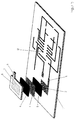
Figur 4- den Aufbau und die Einzelteile eines galvanischen Elements gemäß der Erfindung,
Figur 5- die Anordnung zusätzlicher Leiterbahnen im Zusammenhang mit einem erfindungsgemäßen Element,
Figur 6 und 7- die Ausbildung der Metallisierung auf dem Kunststoffmaterial bzw. Kunststoffverbundmaterial und
Figur 8- eine vorgeformte tiefgezogene Kunststoffmetallverbundfolie mit erfindungsgemäßer Metallisierung.
- Figure 1
- 3 shows a section through a galvanic element according to the invention along the line AA in FIG. 2,
- Figure 2
- a top view of such an element,
- Figure 3
- a further embodiment of a galvanic element according to the invention,
- Figure 4
- the structure and the individual parts of a galvanic element according to the invention,
- Figure 5
- the arrangement of additional conductor tracks in connection with an element according to the invention,
- Figures 6 and 7
- the formation of the metallization on the plastic material or plastic composite material and
- Figure 8
- a preformed thermoformed plastic-metal composite film with metallization according to the invention.
Wie insbesondere Figur 4 zeigt, besteht ein erfindungsgemäßes galvanisches
Element aus einer ersten Kunststofffolie 1, die partiell mit einer
Metallisierung 2 versehen ist, und einer zweiten Kunststofffolie 7, die
ebenfalls mit einer Metallisierung 8 versehen ist. Die das Gehäuse bildenden
Folien 1 bzw. 7 können dabei Kunststofffolien sein. Sie sind vorzugsweise
Kunststoffmetallverbundfolien mit einer inneren Aluminiumschicht,
sodass eine hohe Wasserdampfsperre und niedrige Gasdiffusionsrate
erreicht werden. Eine solche Verbundfolie besteht beispielsweise
aus einer äußeren Polyamidschicht 1 a, 7a, einer mittleren
Aluminiumschicht 1b, 7b und einer inneren Polypropylenschicht 1c, 7c,
welche jeweils die der Form der Elektrode angepassten Metallisierung
trägt. Beispielsweise werden die Folien mittels einer Vakuumbeschichtung
auf der Polypropylenseite partiell metallisiert. Die Fläche der Metallisierung
ist dabei insbesondere etwas kleiner oder praktisch gleich der
Größe der Elektroden 5 und 6.As FIG. 4 in particular shows, there is a galvanic according to the invention
Element made of a
Die positive Elektrode 5 kann beispielsweise eine MnO2 oder LiCoO2 -
Elektrode oder eine LixMnO2 -Elektrode sein. Die negative Elektrode 6
kann aus Lithiummetall, einer Lithiummetall-Legierung, bestehen oder
eine Lithium-interkalierende Graphitelektrode sein. Der Separator 4 ist
beispielsweise eine Polypropylenfolie, Polyethylenfolie oder ein Vlies
aus diesen Materialien.The
Nach dem Zuordnen der in Figur 4 dargestellten Halbteile und Zugabe
eines organischen Elektrolyten werden die Verbundfolien 1 und 7 unter
Vakuum in der nichtmetallisierten Dichtungszone 10 und über der
Durchführung der Kontakte thermisch versiegelt. Alternativ werden sie
miteinander mittels eines als Siegelrahmen ausgebildeten Schmelzklebers
11 verklebt.After assigning the half parts shown in Figure 4 and adding
of an organic electrolyte, the
Den Querschnitt durch eine solche fertige Zelle zeigt Figur 1. Die Ableiterfahnen
3 bzw. 9, die mit der Metallisierung 2 bzw. 8 in Verbindung
stehen, bilden die äußeren Stromableiter der Zelle. Dies ist aus Figur 2
ersichtlich, die die gleiche Zelle in teilweise geschnittener Draufsicht
zeigt. FIG. 1 shows the cross section through such a
Die Ausführungsform eines galvanischen Elements gemäß Figur 3 unterscheidet
sich von der Ausführungsform gemäß Figur 1 im wesentlichen
dadurch, dass hier ein gefaltetes Elektrodenpaket verwendet wird.
Dieses besteht aus Anode 5 und Kathode 6 mit zwischenliegendem Separator
4.The embodiment of a galvanic element according to FIG. 3 differs
differs essentially from the embodiment according to FIG
in that a folded electrode package is used here.
This consists of
Besonders vorteilhaft ist es, dass bei Verwendung von Polymerelektroden, wie sie eingangs erläutert wurden, diese Elektroden, die beispielsweise aus den aktiven Materialien und PVDF als Binder bestehen, diese direkt auf die metallisierten Verbundfolien als Träger auflaminiert werden können. Bei Verwendung so hergestellter Elektroden in einer Anordnung gemäß Figur 3, bei der anstelle eines Stapels von Elektroden, eine gefaltete Elektrode Anwendung findet, ist es möglich, die Zelle auch mit höheren Strömen zu belasten.It is particularly advantageous that when using polymer electrodes, as explained at the beginning, these electrodes, for example consist of the active materials and PVDF as a binder, these are laminated directly onto the metallized composite films as a carrier can. When using electrodes manufactured in this way in an arrangement according to Figure 3, in which instead of a stack of electrodes, a folded Electrode is used, it is possible to use the cell too load higher currents.
Die Metallisierung der Folien, die bereichsweise erfolgt, kann großflächig
oder auch in Form eines Musters ausgeführt werden, wie dies den Figuren
7a bis 7d zu entnehmen ist. Figur 6 zeigt dabei die Anordnung der
Metallisierungen auf einem Kunststoffverbundband 13. Dabei sind die
Bereiche 2 mit Aluminium und die Bereiche 8 mit Kupfer metallisiert.The metallization of the foils, which takes place in certain areas, can be extensive
or can also be executed in the form of a pattern, as is the case with the figures
7a to 7d can be seen. Figure 6 shows the arrangement of the
Metallizations on a plastic
Wenn die Metallisierung nicht vollflächig ausgeführt ist, so kann bei Verwendung von Elektroden, die auf eine Metallfolie aufgebracht oder laminiert sind, diese Metallfolie durch thermisches Aufsiegeln mit den freien, nichtmetallisierten Bereichen der Kunststoffverbundfolie verbunden werden. So verbessert sich die Kontaktierung von Metallfolieableiter der Elektrode und Metallisierung der Verbundfolie.If the metallization is not carried out over the entire surface, then at Use of electrodes that are applied to a metal foil or are laminated, this metal foil by thermal sealing with the free, non-metallized areas of the plastic composite film connected become. This improves the contacting of metal foil arresters the electrode and metallization of the composite film.
Wie in Figur 5 dargestellt, kann mindestens eine der Kunststofffolien
oder Kunststoffmetallverbundfolien gleichzeitig der Träger von Leiterbahnen
12 für weitere elektronische Bausteine sein. Dabei wird diese
Metallisierung gleichzeitig mit der Metallisierung der Kollektorfläche im
Zellengehäuses aufgebracht. Die Kollektorflächen 2 und 8 und die Leiterbahnen
12 können mittels Vakuumbeschichtung, durch stromlose
oder galvanische Metallabscheidung oder durch Bedrucken mittels leitfähiger
Pasten aufgebracht werden. Die mittels Vakuumbeschichtung,
stromloser oder galvanischer Metallabscheidung aufgebrachten Kollektorflächen
2 und 8 und die Leiterbahnen 12 können über Maskentechnik
direkt strukturiert erzeugt werden. Alternativ dazu kann auch die Metallisierung
jeweils vollflächig erfolgen. Dabei wird die jeweilige Struktur mittels
Laserablation oder konventioneller Photolithographie in Verbindung
mit chemischer Ätztechnik oder Plasmaätzen hergestellt.As shown in Figure 5, at least one of the plastic films
or plastic metal composite films at the same time the carrier of conductor tracks
12 for other electronic components. In doing so, this will
Metallization simultaneously with the metallization of the collector surface in the
Cell housing applied. The
Es ist besonders vorteilhaft, eine erfindungsgemäß hergestellte Zelle in
einer sogenannten Smart-Card, wie sie beispielsweise in der DE 101 02
125 A1 beschrieben ist, zu verwenden. Die innerhalb der Verbundfolie
angeordnete Metallschicht kann aus Aluminium, Kupfer oder Nickel als
Dampf- oder Gasdiffusionssperre bestehen. Es kann vorteilhaft sein,
insbesondere die Dicke der Ableiterfahnen 3 und 9 durch einen zusätzlichen
Metallisierungsschritt zu erhöhen oder diese Bereiche mit einer
zusätzlichen Metallfolie zu verstärken. Die Kunststofffolie bzw. Kunststoffmetallverbundfolie
besitzt eine Dicke von 5 bis 400 µm, insbesondere
eine Dicke von 10 bis 150 µm. Die Metallisierung, die auf diese Verbundfolie
aufgebracht wird, besitzt eine Dicke von 0,02 bis 30 µm, vorzugsweise
eine Dicke von ca. 0,1 bis 5 µm.It is particularly advantageous to in a cell manufactured according to the invention
a so-called smart card, as described, for example, in DE 101 02
125 A1 is to be used. The inside of the composite film
Arranged metal layer can be made of aluminum, copper or nickel
Vapor or gas diffusion barrier exist. It can be beneficial
in particular the thickness of the
Es ist insbesondere vorteilhaft, mindestens eine der Kunststofffolien bzw. Kunststoffmetallverbundfolien durch einen Tiefziehvorgang so vorzuformen, dass eine Aufnahme für eine Elektrode oder den Elektrodensatz mit Separator entsteht. Dies ist in Figur 8 dargestellt.It is particularly advantageous to use at least one of the plastic films or to preform plastic-metal composite foils by a deep-drawing process, that a holder for an electrode or the electrode set with separator. This is shown in Figure 8.
Claims (10)
Applications Claiming Priority (2)
| Application Number | Priority Date | Filing Date | Title |
|---|---|---|---|
| DE10219424 | 2002-05-02 | ||
| DE10219424A DE10219424A1 (en) | 2002-05-02 | 2002-05-02 | Galvanic element with thin electrodes |
Publications (2)
| Publication Number | Publication Date |
|---|---|
| EP1359633A1 true EP1359633A1 (en) | 2003-11-05 |
| EP1359633B1 EP1359633B1 (en) | 2009-09-30 |
Family
ID=28798948
Family Applications (1)
| Application Number | Title | Priority Date | Filing Date |
|---|---|---|---|
| EP03008511A Expired - Lifetime EP1359633B1 (en) | 2002-05-02 | 2003-04-12 | Galvanic element with thin electrodes |
Country Status (7)
| Country | Link |
|---|---|
| US (1) | US20030228517A1 (en) |
| EP (1) | EP1359633B1 (en) |
| JP (1) | JP4460847B2 (en) |
| KR (1) | KR20030086898A (en) |
| CN (1) | CN1307737C (en) |
| AT (1) | ATE444572T1 (en) |
| DE (2) | DE10219424A1 (en) |
Cited By (4)
| Publication number | Priority date | Publication date | Assignee | Title |
|---|---|---|---|---|
| EP1655794A3 (en) * | 2004-11-03 | 2008-06-04 | Antig Technology Co., Ltd. | Double-electrode plate with electrical circuitry layer laminate and the secondary battery with the same |
| WO2012072222A1 (en) * | 2010-11-29 | 2012-06-07 | Zentrum Fuer Sonnenenergie- Und Wasserstoff-Forschung Baden-Wuerttemberg, Gemeinnützige Stiftung | Battery electrode and a method for producing same |
| WO2012072221A1 (en) * | 2010-11-29 | 2012-06-07 | Zentrum Fuer Sonnenenergie- Und Wasserstoff-Forschung Baden-Wuerttemberg, Gemeinnützige Stiftung | Battery electrode and method for producing same |
| WO2014021970A3 (en) * | 2012-05-08 | 2014-04-03 | Battelle Memorial Institute | Multifunctional cell for structural applications |
Families Citing this family (24)
| Publication number | Priority date | Publication date | Assignee | Title |
|---|---|---|---|---|
| KR100712423B1 (en) * | 2003-12-02 | 2007-04-27 | 주식회사 아이링고 | Chain Block Toys |
| US7776468B2 (en) * | 2004-03-18 | 2010-08-17 | The Gillette Company | Wafer alkaline cell |
| US7820329B2 (en) * | 2004-03-18 | 2010-10-26 | The Procter & Gamble Company | Wafer alkaline cell |
| US7413828B2 (en) * | 2004-03-18 | 2008-08-19 | The Gillette Company | Wafer alkaline cell |
| US7531271B2 (en) * | 2004-03-18 | 2009-05-12 | The Gillette Company | Wafer alkaline cell |
| TWI236175B (en) * | 2004-05-14 | 2005-07-11 | Antig Tech Co Ltd | Secondary battery |
| DE102004033456A1 (en) * | 2004-07-07 | 2006-01-26 | Varta Microbattery Gmbh | Method for testing the tightness or stability of galvanic elements |
| DE102005017682A1 (en) * | 2005-04-08 | 2006-10-12 | Varta Microbattery Gmbh | Galvanic element |
| DE102006053273A1 (en) * | 2006-11-06 | 2008-05-08 | Varta Microbattery Gmbh | Galvanic element with short-circuit protection |
| CN102144315B (en) * | 2008-09-05 | 2014-04-30 | 雷纳塔股份公司 | Thin film battery |
| DE102008059944B4 (en) * | 2008-12-02 | 2013-03-07 | Li-Tec Battery Gmbh | Single cell battery, method of making the battery and its use |
| DE102008059951B4 (en) * | 2008-12-02 | 2013-04-25 | Daimler Ag | Single cell for a battery, method for making a single cell and their use |
| DE102008059946B4 (en) * | 2008-12-02 | 2013-02-28 | Daimler Ag | Einzelellzelle a battery, battery with a plurality of single cells and method for producing a frame for the single cell |
| CN102320165A (en) * | 2011-05-10 | 2012-01-18 | 王亚奇 | Internal-heat-generation reinforced composite plate adhered by adopting environment-friendly UV (ultraviolet) shadow-free glue |
| CN102291859A (en) * | 2011-08-06 | 2011-12-21 | 王亚奇 | Method for manufacturing internal-heating reinforced composite board connected by hot-melting wafer |
| KR101286620B1 (en) * | 2011-08-26 | 2013-07-15 | 지에스나노텍 주식회사 | Thin film battery and method for fabricating the same |
| DE102011084019A1 (en) | 2011-10-05 | 2013-04-11 | Varta Microbattery Gmbh | Battery with fibrous or filamentary electrode |
| DE102011086899A1 (en) | 2011-11-22 | 2013-05-23 | Varta Microbattery Gmbh | Printed batteries |
| DE102016101329A1 (en) | 2016-01-26 | 2017-07-27 | Schreiner Group Gmbh & Co. Kg | Foil construction for a battery for dispensing on a round body |
| DE102016101325A1 (en) | 2016-01-26 | 2017-07-27 | Schreiner Group Gmbh & Co. Kg | Foil construction for a battery for dispensing on a round body |
| DE102017214770B3 (en) * | 2017-08-23 | 2019-02-14 | VW-VM Forschungsgesellschaft mbH & Co. KG | Method for determining a state or a state change of an electrochemical energy storage device and energy storage device prepared therefor |
| US11764392B2 (en) * | 2018-03-01 | 2023-09-19 | Analog Devices, Inc. | Battery assembly and method of manufacturing the same |
| WO2025053693A1 (en) * | 2023-09-06 | 2025-03-13 | 주식회사 엘지에너지솔루션 | Pouch sheet, pouch-type battery case, and method for manufacturing battery case |
| KR102791906B1 (en) * | 2023-09-06 | 2025-04-08 | 주식회사 엘지에너지솔루션 | Pouch sheet, pouch-type battery case, and manufacturing method of battery case |
Citations (6)
| Publication number | Priority date | Publication date | Assignee | Title |
|---|---|---|---|---|
| WO1994020996A1 (en) * | 1993-03-05 | 1994-09-15 | Bell Communications Research, Inc. | Rechargeable lithium intercalation battery with hybrid polymeric electrolyte |
| WO1995015589A1 (en) * | 1993-11-30 | 1995-06-08 | Bell Communications Research, Inc. | Electrolyte activatable lithium-ion rechargeable battery cell and method of making same |
| WO1997033326A1 (en) * | 1996-03-04 | 1997-09-12 | Bell Communications Research, Inc. | Electrical connection for a polymeric laminate battery structure |
| WO2000072394A1 (en) * | 1999-05-20 | 2000-11-30 | Telcordia Technologies, Inc. | Method of making laminated polymeric rechargeable battery cells |
| GB2357896A (en) * | 1999-12-14 | 2001-07-04 | Sanyo Electric Co | Lithium secondary battery and battery device comprising same |
| WO2001097300A1 (en) * | 2000-06-09 | 2001-12-20 | Ntk Powerdex, Inc. | Ic card with thin battery |
Family Cites Families (9)
| Publication number | Priority date | Publication date | Assignee | Title |
|---|---|---|---|---|
| US4070528A (en) * | 1975-04-30 | 1978-01-24 | Esb Incorporated | Battery having porous inherently sealable separator |
| US5540741A (en) * | 1993-03-05 | 1996-07-30 | Bell Communications Research, Inc. | Lithium secondary battery extraction method |
| US5587253A (en) * | 1993-03-05 | 1996-12-24 | Bell Communications Research, Inc. | Low resistance rechargeable lithium-ion battery |
| US5470357A (en) * | 1993-03-05 | 1995-11-28 | Bell Communications Research, Inc. | Method of making a laminated lithium-ion rechargeable battery cell |
| US5418091A (en) * | 1993-03-05 | 1995-05-23 | Bell Communications Research, Inc. | Polymeric electrolytic cell separator membrane |
| US5429891A (en) * | 1993-03-05 | 1995-07-04 | Bell Communications Research, Inc. | Crosslinked hybrid electrolyte film and methods of making and using the same |
| EP1071151A1 (en) * | 1999-07-23 | 2001-01-24 | Nec Corporation | Method for producing film packed battery |
| JP2001043892A (en) * | 1999-07-29 | 2001-02-16 | Kyocera Corp | Lithium battery |
| US7201997B2 (en) * | 2000-12-28 | 2007-04-10 | Matsushita Electric Industrial Co., Ltd. | Non-aqueous electrolyte battery |
-
2002
- 2002-05-02 DE DE10219424A patent/DE10219424A1/en not_active Withdrawn
-
2003
- 2003-04-12 EP EP03008511A patent/EP1359633B1/en not_active Expired - Lifetime
- 2003-04-12 DE DE50311953T patent/DE50311953D1/en not_active Expired - Lifetime
- 2003-04-12 AT AT03008511T patent/ATE444572T1/en not_active IP Right Cessation
- 2003-04-25 KR KR10-2003-0026181A patent/KR20030086898A/en not_active Ceased
- 2003-04-29 US US10/425,385 patent/US20030228517A1/en not_active Abandoned
- 2003-05-02 JP JP2003127460A patent/JP4460847B2/en not_active Expired - Fee Related
- 2003-05-02 CN CNB031407595A patent/CN1307737C/en not_active Expired - Fee Related
Patent Citations (7)
| Publication number | Priority date | Publication date | Assignee | Title |
|---|---|---|---|---|
| WO1994020996A1 (en) * | 1993-03-05 | 1994-09-15 | Bell Communications Research, Inc. | Rechargeable lithium intercalation battery with hybrid polymeric electrolyte |
| US5460904A (en) * | 1993-08-23 | 1995-10-24 | Bell Communications Research, Inc. | Electrolyte activatable lithium-ion rechargeable battery cell |
| WO1995015589A1 (en) * | 1993-11-30 | 1995-06-08 | Bell Communications Research, Inc. | Electrolyte activatable lithium-ion rechargeable battery cell and method of making same |
| WO1997033326A1 (en) * | 1996-03-04 | 1997-09-12 | Bell Communications Research, Inc. | Electrical connection for a polymeric laminate battery structure |
| WO2000072394A1 (en) * | 1999-05-20 | 2000-11-30 | Telcordia Technologies, Inc. | Method of making laminated polymeric rechargeable battery cells |
| GB2357896A (en) * | 1999-12-14 | 2001-07-04 | Sanyo Electric Co | Lithium secondary battery and battery device comprising same |
| WO2001097300A1 (en) * | 2000-06-09 | 2001-12-20 | Ntk Powerdex, Inc. | Ic card with thin battery |
Cited By (7)
| Publication number | Priority date | Publication date | Assignee | Title |
|---|---|---|---|---|
| EP1655794A3 (en) * | 2004-11-03 | 2008-06-04 | Antig Technology Co., Ltd. | Double-electrode plate with electrical circuitry layer laminate and the secondary battery with the same |
| WO2012072222A1 (en) * | 2010-11-29 | 2012-06-07 | Zentrum Fuer Sonnenenergie- Und Wasserstoff-Forschung Baden-Wuerttemberg, Gemeinnützige Stiftung | Battery electrode and a method for producing same |
| WO2012072221A1 (en) * | 2010-11-29 | 2012-06-07 | Zentrum Fuer Sonnenenergie- Und Wasserstoff-Forschung Baden-Wuerttemberg, Gemeinnützige Stiftung | Battery electrode and method for producing same |
| US9966592B2 (en) | 2010-11-29 | 2018-05-08 | Zentrum Fuer Sonnenenergie-Und Wasserstoff-Forschung Baden-Wuerttemberg Gemeinnuetzige Stiftung | Battery electrode and method for producing same |
| US10062897B2 (en) | 2010-11-29 | 2018-08-28 | Zentrum Fuer Sonnenenergie- Und Wasserstoff-Forschung Baden-Wuerttemberg Gemeinnuetzige Stiftung | Battery electrode and a method for producing same |
| WO2014021970A3 (en) * | 2012-05-08 | 2014-04-03 | Battelle Memorial Institute | Multifunctional cell for structural applications |
| US9520580B2 (en) | 2012-05-08 | 2016-12-13 | Battelle Memorial Institute | Multifunctional cell for structural applications |
Also Published As
| Publication number | Publication date |
|---|---|
| JP4460847B2 (en) | 2010-05-12 |
| DE50311953D1 (en) | 2009-11-12 |
| US20030228517A1 (en) | 2003-12-11 |
| CN1462082A (en) | 2003-12-17 |
| DE10219424A1 (en) | 2003-11-20 |
| JP2004006346A (en) | 2004-01-08 |
| CN1307737C (en) | 2007-03-28 |
| EP1359633B1 (en) | 2009-09-30 |
| KR20030086898A (en) | 2003-11-12 |
| ATE444572T1 (en) | 2009-10-15 |
Similar Documents
| Publication | Publication Date | Title |
|---|---|---|
| EP1359633B1 (en) | Galvanic element with thin electrodes | |
| DE10225041B4 (en) | Galvanic element | |
| DE69328411T2 (en) | Rectangular cell and method of manufacture | |
| DE60222003T2 (en) | BENDING THIN BATTERY AND METHOD FOR THE PRODUCTION THEREOF | |
| DE102013102018A1 (en) | Terminal tongue e.g. negative electrode terminal tongue, for e.g. lithium ion secondary battery, has two projection portions sets formed at regions of insulation films and protruded outward in thickness directions of films, respectively | |
| EP3520163A1 (en) | Method for producing an electrode unit for a battery cell and electrode unit | |
| DE112017005247B4 (en) | Energy storage device and manufacturing method of an energy storage device | |
| DE102010044080A1 (en) | Production process for electrodes | |
| DE102022130710A1 (en) | SECONDARY BATTERY | |
| DE102022111291A1 (en) | solid state battery | |
| EP3447819B1 (en) | Secondary miniature battery with metal housing and method for its manufacturing | |
| DE102016217369A1 (en) | Electrode with increased active material content | |
| DE102017217676A1 (en) | Battery cell and method for producing a battery cell | |
| DE10047206A1 (en) | Housing for electrochemical cells | |
| EP3300141B1 (en) | Method for the preparation of an electrode stack for a battery cell and battery cell | |
| DE102022124854A1 (en) | METAL-POLYMER HYBRID CURRENT COLLECTOR FOR A BATTERY ELECTRODE AND METHOD OF PRODUCTION THEREOF | |
| EP2633571A2 (en) | Electrochemical cell and method for producing same | |
| DE102008059963B4 (en) | Single cell for a battery and method for its production | |
| WO2009074279A2 (en) | Main lead for a galvanic cell | |
| DE102012213420A1 (en) | Method for producing a connection contact for an electrode of an electrochemical store, method for producing an electrochemical store and electrochemical store | |
| EP4343879A2 (en) | Method for producing a semi-finished product of a solid-state battery, semi-finished product of a solid-state battery and solid-state battery | |
| DE102021213444B3 (en) | Housing for storing an ionic liquid containing aluminum chloride and battery cell with such a housing | |
| EP3605697B1 (en) | Method for producing an electrode separator coil, electrode separator coil and button cell comprising such a coil | |
| DE112022001408T5 (en) | SOLID STATE BATTERY | |
| EP3711103A1 (en) | Thin, secondary miniature cell having a metal housing closed by means of a plastic cover, and method for producing said miniature cell |
Legal Events
| Date | Code | Title | Description |
|---|---|---|---|
| PUAI | Public reference made under article 153(3) epc to a published international application that has entered the european phase |
Free format text: ORIGINAL CODE: 0009012 |
|
| AK | Designated contracting states |
Kind code of ref document: A1 Designated state(s): AT BE BG CH CY CZ DE DK EE ES FI FR GB GR HU IE IT LI LU MC NL PT RO SE SI SK TR |
|
| AX | Request for extension of the european patent |
Extension state: AL LT LV MK RO |
|
| 17P | Request for examination filed |
Effective date: 20031203 |
|
| AKX | Designation fees paid |
Designated state(s): AT BE BG CH CY CZ DE DK EE ES FI FR GB GR HU IE IT LI LU MC NL PT RO SE SI SK TR |
|
| 17Q | First examination report despatched |
Effective date: 20041213 |
|
| GRAP | Despatch of communication of intention to grant a patent |
Free format text: ORIGINAL CODE: EPIDOSNIGR1 |
|
| GRAS | Grant fee paid |
Free format text: ORIGINAL CODE: EPIDOSNIGR3 |
|
| GRAA | (expected) grant |
Free format text: ORIGINAL CODE: 0009210 |
|
| AK | Designated contracting states |
Kind code of ref document: B1 Designated state(s): AT BE BG CH CY CZ DE DK EE ES FI FR GB GR HU IE IT LI LU MC NL PT RO SE SI SK TR |
|
| REG | Reference to a national code |
Ref country code: GB Ref legal event code: FG4D Free format text: NOT ENGLISH Ref country code: CH Ref legal event code: EP |
|
| REG | Reference to a national code |
Ref country code: IE Ref legal event code: FG4D |
|
| REF | Corresponds to: |
Ref document number: 50311953 Country of ref document: DE Date of ref document: 20091112 Kind code of ref document: P |
|
| PG25 | Lapsed in a contracting state [announced via postgrant information from national office to epo] |
Ref country code: FI Free format text: LAPSE BECAUSE OF FAILURE TO SUBMIT A TRANSLATION OF THE DESCRIPTION OR TO PAY THE FEE WITHIN THE PRESCRIBED TIME-LIMIT Effective date: 20090930 Ref country code: SE Free format text: LAPSE BECAUSE OF FAILURE TO SUBMIT A TRANSLATION OF THE DESCRIPTION OR TO PAY THE FEE WITHIN THE PRESCRIBED TIME-LIMIT Effective date: 20090930 |
|
| PG25 | Lapsed in a contracting state [announced via postgrant information from national office to epo] |
Ref country code: SI Free format text: LAPSE BECAUSE OF FAILURE TO SUBMIT A TRANSLATION OF THE DESCRIPTION OR TO PAY THE FEE WITHIN THE PRESCRIBED TIME-LIMIT Effective date: 20090930 |
|
| NLV1 | Nl: lapsed or annulled due to failure to fulfill the requirements of art. 29p and 29m of the patents act | ||
| PG25 | Lapsed in a contracting state [announced via postgrant information from national office to epo] |
Ref country code: RO Free format text: LAPSE BECAUSE OF FAILURE TO SUBMIT A TRANSLATION OF THE DESCRIPTION OR TO PAY THE FEE WITHIN THE PRESCRIBED TIME-LIMIT Effective date: 20090930 Ref country code: EE Free format text: LAPSE BECAUSE OF FAILURE TO SUBMIT A TRANSLATION OF THE DESCRIPTION OR TO PAY THE FEE WITHIN THE PRESCRIBED TIME-LIMIT Effective date: 20090930 Ref country code: ES Free format text: LAPSE BECAUSE OF FAILURE TO SUBMIT A TRANSLATION OF THE DESCRIPTION OR TO PAY THE FEE WITHIN THE PRESCRIBED TIME-LIMIT Effective date: 20100110 Ref country code: PT Free format text: LAPSE BECAUSE OF FAILURE TO SUBMIT A TRANSLATION OF THE DESCRIPTION OR TO PAY THE FEE WITHIN THE PRESCRIBED TIME-LIMIT Effective date: 20100201 Ref country code: CZ Free format text: LAPSE BECAUSE OF FAILURE TO SUBMIT A TRANSLATION OF THE DESCRIPTION OR TO PAY THE FEE WITHIN THE PRESCRIBED TIME-LIMIT Effective date: 20090930 |
|
| REG | Reference to a national code |
Ref country code: IE Ref legal event code: FD4D |
|
| PG25 | Lapsed in a contracting state [announced via postgrant information from national office to epo] |
Ref country code: SK Free format text: LAPSE BECAUSE OF FAILURE TO SUBMIT A TRANSLATION OF THE DESCRIPTION OR TO PAY THE FEE WITHIN THE PRESCRIBED TIME-LIMIT Effective date: 20090930 Ref country code: CY Free format text: LAPSE BECAUSE OF FAILURE TO SUBMIT A TRANSLATION OF THE DESCRIPTION OR TO PAY THE FEE WITHIN THE PRESCRIBED TIME-LIMIT Effective date: 20090930 |
|
| PG25 | Lapsed in a contracting state [announced via postgrant information from national office to epo] |
Ref country code: NL Free format text: LAPSE BECAUSE OF FAILURE TO SUBMIT A TRANSLATION OF THE DESCRIPTION OR TO PAY THE FEE WITHIN THE PRESCRIBED TIME-LIMIT Effective date: 20090930 Ref country code: DK Free format text: LAPSE BECAUSE OF FAILURE TO SUBMIT A TRANSLATION OF THE DESCRIPTION OR TO PAY THE FEE WITHIN THE PRESCRIBED TIME-LIMIT Effective date: 20090930 Ref country code: IE Free format text: LAPSE BECAUSE OF FAILURE TO SUBMIT A TRANSLATION OF THE DESCRIPTION OR TO PAY THE FEE WITHIN THE PRESCRIBED TIME-LIMIT Effective date: 20090930 |
|
| PLBE | No opposition filed within time limit |
Free format text: ORIGINAL CODE: 0009261 |
|
| STAA | Information on the status of an ep patent application or granted ep patent |
Free format text: STATUS: NO OPPOSITION FILED WITHIN TIME LIMIT |
|
| 26N | No opposition filed |
Effective date: 20100701 |
|
| PG25 | Lapsed in a contracting state [announced via postgrant information from national office to epo] |
Ref country code: GR Free format text: LAPSE BECAUSE OF FAILURE TO SUBMIT A TRANSLATION OF THE DESCRIPTION OR TO PAY THE FEE WITHIN THE PRESCRIBED TIME-LIMIT Effective date: 20091231 |
|
| BERE | Be: lapsed |
Owner name: VARTA MICROBATTERY G.M.B.H. Effective date: 20100430 |
|
| PG25 | Lapsed in a contracting state [announced via postgrant information from national office to epo] |
Ref country code: MC Free format text: LAPSE BECAUSE OF NON-PAYMENT OF DUE FEES Effective date: 20100430 |
|
| REG | Reference to a national code |
Ref country code: CH Ref legal event code: PL |
|
| PG25 | Lapsed in a contracting state [announced via postgrant information from national office to epo] |
Ref country code: CH Free format text: LAPSE BECAUSE OF NON-PAYMENT OF DUE FEES Effective date: 20100430 Ref country code: LI Free format text: LAPSE BECAUSE OF NON-PAYMENT OF DUE FEES Effective date: 20100430 |
|
| PG25 | Lapsed in a contracting state [announced via postgrant information from national office to epo] |
Ref country code: BE Free format text: LAPSE BECAUSE OF NON-PAYMENT OF DUE FEES Effective date: 20100430 Ref country code: IT Free format text: LAPSE BECAUSE OF FAILURE TO SUBMIT A TRANSLATION OF THE DESCRIPTION OR TO PAY THE FEE WITHIN THE PRESCRIBED TIME-LIMIT Effective date: 20090930 |
|
| PG25 | Lapsed in a contracting state [announced via postgrant information from national office to epo] |
Ref country code: AT Free format text: LAPSE BECAUSE OF NON-PAYMENT OF DUE FEES Effective date: 20100412 |
|
| REG | Reference to a national code |
Ref country code: DE Ref legal event code: R082 Ref document number: 50311953 Country of ref document: DE Representative=s name: PATENTANWAELTE RUFF, WILHELM, BEIER, DAUSTER &, DE |
|
| REG | Reference to a national code |
Ref country code: DE Ref legal event code: R082 Ref document number: 50311953 Country of ref document: DE Representative=s name: PATENTANWAELTE RUFF, WILHELM, BEIER, DAUSTER &, DE Effective date: 20120306 Ref country code: DE Ref legal event code: R081 Ref document number: 50311953 Country of ref document: DE Owner name: VARTA MICROBATTERY GMBH, DE Free format text: FORMER OWNER: VARTA MICROBATTERY GMBH, 30419 HANNOVER, DE Effective date: 20120306 |
|
| PGFP | Annual fee paid to national office [announced via postgrant information from national office to epo] |
Ref country code: DE Payment date: 20120502 Year of fee payment: 10 |
|
| PGFP | Annual fee paid to national office [announced via postgrant information from national office to epo] |
Ref country code: FR Payment date: 20120511 Year of fee payment: 10 Ref country code: GB Payment date: 20120423 Year of fee payment: 10 |
|
| PG25 | Lapsed in a contracting state [announced via postgrant information from national office to epo] |
Ref country code: BG Free format text: LAPSE BECAUSE OF FAILURE TO SUBMIT A TRANSLATION OF THE DESCRIPTION OR TO PAY THE FEE WITHIN THE PRESCRIBED TIME-LIMIT Effective date: 20090930 Ref country code: HU Free format text: LAPSE BECAUSE OF FAILURE TO SUBMIT A TRANSLATION OF THE DESCRIPTION OR TO PAY THE FEE WITHIN THE PRESCRIBED TIME-LIMIT Effective date: 20100401 Ref country code: LU Free format text: LAPSE BECAUSE OF NON-PAYMENT OF DUE FEES Effective date: 20100412 |
|
| PG25 | Lapsed in a contracting state [announced via postgrant information from national office to epo] |
Ref country code: TR Free format text: LAPSE BECAUSE OF FAILURE TO SUBMIT A TRANSLATION OF THE DESCRIPTION OR TO PAY THE FEE WITHIN THE PRESCRIBED TIME-LIMIT Effective date: 20090930 |
|
| GBPC | Gb: european patent ceased through non-payment of renewal fee |
Effective date: 20130412 |
|
| PG25 | Lapsed in a contracting state [announced via postgrant information from national office to epo] |
Ref country code: DE Free format text: LAPSE BECAUSE OF NON-PAYMENT OF DUE FEES Effective date: 20131101 Ref country code: GB Free format text: LAPSE BECAUSE OF NON-PAYMENT OF DUE FEES Effective date: 20130412 |
|
| REG | Reference to a national code |
Ref country code: FR Ref legal event code: ST Effective date: 20131231 |
|
| REG | Reference to a national code |
Ref country code: DE Ref legal event code: R119 Ref document number: 50311953 Country of ref document: DE Effective date: 20131101 |
|
| PG25 | Lapsed in a contracting state [announced via postgrant information from national office to epo] |
Ref country code: FR Free format text: LAPSE BECAUSE OF NON-PAYMENT OF DUE FEES Effective date: 20130430 |