EP1359480A1 - Vibration suppression positioning controller - Google Patents
Vibration suppression positioning controller Download PDFInfo
- Publication number
- EP1359480A1 EP1359480A1 EP02716376A EP02716376A EP1359480A1 EP 1359480 A1 EP1359480 A1 EP 1359480A1 EP 02716376 A EP02716376 A EP 02716376A EP 02716376 A EP02716376 A EP 02716376A EP 1359480 A1 EP1359480 A1 EP 1359480A1
- Authority
- EP
- European Patent Office
- Prior art keywords
- command
- position command
- output
- zero
- target position
- Prior art date
- Legal status (The legal status is an assumption and is not a legal conclusion. Google has not performed a legal analysis and makes no representation as to the accuracy of the status listed.)
- Granted
Links
Images




Classifications
-
- G—PHYSICS
- G05—CONTROLLING; REGULATING
- G05D—SYSTEMS FOR CONTROLLING OR REGULATING NON-ELECTRIC VARIABLES
- G05D3/00—Control of position or direction
- G05D3/12—Control of position or direction using feedback
-
- G—PHYSICS
- G05—CONTROLLING; REGULATING
- G05B—CONTROL OR REGULATING SYSTEMS IN GENERAL; FUNCTIONAL ELEMENTS OF SUCH SYSTEMS; MONITORING OR TESTING ARRANGEMENTS FOR SUCH SYSTEMS OR ELEMENTS
- G05B11/00—Automatic controllers
- G05B11/01—Automatic controllers electric
- G05B11/36—Automatic controllers electric with provision for obtaining particular characteristics, e.g. proportional, integral, differential
-
- G—PHYSICS
- G05—CONTROLLING; REGULATING
- G05B—CONTROL OR REGULATING SYSTEMS IN GENERAL; FUNCTIONAL ELEMENTS OF SUCH SYSTEMS; MONITORING OR TESTING ARRANGEMENTS FOR SUCH SYSTEMS OR ELEMENTS
- G05B5/00—Anti-hunting arrangements
- G05B5/01—Anti-hunting arrangements electric
Definitions
- the invention relates to a positioning controller for performing positioning operation by driving load through use of a motor, and more particularly, to a technique for damping low-frequency vibration in a load or in a bed on which the load is to be disposed.
- reference numeral 31 designates an S-shaped position command generator; 32 designates a metastablepre-filter; 33 designates a semi-closed feedback position control system; 33a designates a transfer function from a position command of a feedback control system to the position of a motor; and 33b designates a transfer function from the position of the motor to the position of load.
- a natural vibration angular frequency of load in the feedback control system is ⁇ a , which shows a case where a speed pattern ⁇ * M of an S-shaped position command assumes a trapezoidal shape as shown in Fig. 5, wherein an acceleration time and a deceleration time are equal to each other.
- t A denotes an acceleration/deceleration time
- (t D -t A ) denotes a constant speed time.
- Dampening control is accomplished by setting ⁇ an so as to satisfy any term of Equation (2).
- the related art presents the following problems.
- the invention aims at providing a vibration-damping positioning controller which can fix a position command of a feedback control system to a target position by setting an output from a prefilter to zero when the position command of the feedback control system coincides with a target command, thereby enabling stable positioning operation within a short period of time.
- a vibration-damping positioning controller produces a position command when given a differential value of a target position command that changes in a predetermined pattern, and causes load to follow the position command by inputting the position command to the feedback control system
- the controller comprises: an integrator for integrating a differential value of the target position command; a subtracter which subtracts the position command from an output of the intergrator, to thereby output a position command error; a stable prefilter which receives a differential value of the target position command and eliminates a frequency component identical with a vibration pole ⁇ 0 of the feedback control system; command fixing means which receives an output from the stable prefilter and the position command error, judges that the command is started when a differential value of the target position command has changed from zero to a non-zero value, judges that the command is ended when the differential value of the target position command has changed from the non-zero value to zero, outputs zero from the time the position command error has assumed zero after the command is ended until the next command is started, and in other cases
- a vibration-damping positioning controller produces a position command when given a target position command that changes in apredetermined pattern, and causes load to follow the position command by inputting the position command to the feedback control system
- the controller comprises: a differentiator for differentiating the target position command; a subtracter which subtracts the position command from the target position command, to thereby output a position command error; a stable prefilter which receives a differential value of the target position command serving as an output from the differentiator and eliminates a frequency component identical with a vibration pole ⁇ 0 of the feedback control system; command fixing means which receives an output from the stable prefilter and the position command error, judges that the command is started when a differential value of the target position command has changed from zero to a non-zero value, judges that the command is ended when the differential value of the target position command has changed from a non-zero value to zero, outputs zero from the time the position command error has assumed zero after the command is ended until the next command is started, and in other cases
- a target command signal is caused to pass through a stable prefilter.
- a natural vibration frequency component of machinery included in the target command signal is omitted.
- the command signal that has passed through the stable prefilter is stable and smooth.
- the command signal that has passed through the stable prefilter is caused to pass through the command fixing section.
- the final command signal that has been applied to the feedback control system reaches the target position immediately. Accordingly, there is yielded an advantage of the ability to obtain a stable positioning command whose command fixing time is short without inducing mechanical vibrations.
- Fig. 1 is a block diagram showing a first embodiment of the invention
- Fig. 2 is a block diagram showing a second embodiment of the invention
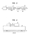
- Fig. 3 is a block diagram showing the configuration of a related-art vibration-damping positioning controller
- Fig. 4 is a system block diagram of the embodiment of the invention.
- Fig. 5 is a view showing a time function pertaining to an S-shaped position command and an command speed pattern; and
- Fig. 6 is a view showing a time function of a related-art position command when t A is constant and the metastable prefilter is embodied in the form of a continuous system.
- Fig. 5 is a view showing a time function pertaining to an S-shaped position command and an command speed pattern
- Fig. 6 is a view showing a time function of a related-art position command when t A is constant and the metastable prefilter is embodied in the form of a continuous system.
- Fig. 5 is a view showing a time function
- FIG. 7 is a view showing a time function of a related-art position command when t A has dropped by 5% and the metastable prefilter is embodied in the form of a continuous system.
- Fig. 8 is a view showing a time function of a related-art position command when t A is constant and the metastable prefilter is embodied in the form of a discrete system.
- Fig. 9 is a view showing a time function of the position command of the invention when t A is constant and the metastable prefilter is embodied in the form of the continuous system.
- Fig. 10 is a view showing a time function of the position command of the invention when t A has dropped by 5% and a stable prefilter is embodied in the form of the continuous system.
- Fig. 11 is a view showing a time function of the position command when t A is constant and the stable prefilter is embodied in the form of the discrete system.
- Figs. 1 and 2 are block diagrams showing first and second embodiments of the invention; and Fig. 4 is a system block diagram to which the invention is applied.
- Fig. 4 wherein reference numeral 41 designates a motor, 43 designates load, 42 designates a power transmission mechanism which connects the motor 41 to the load 43, to thereby transmit torque, 44 designates a bed on which these elements are mounted, and 45 designates support legs for supporting the bed 44.
- the bed 44 receives reactive force of drive force of the motor 41.
- the support legs 45 are of low rigidity, the bed 44 is susceptible to vibration.
- the motor drives the load at high accelerating/decelerating speed; particularly, when the cycle of drive force is close to the natural vibration cycle of the bed 44, the bed 44 becomes apt to vibrate.
- reference numeral 5 designates a feedback control system
- 5a designates a stability term of a transfer function from a position command x *** of the feedback control system 5 to a bed displacement "y"
- 5b designates an instability term of the transfer function.
- ⁇ 0 denotes a natural vibration frequency of the bed 44.
- a differentiator 8 differentiates the target position command x*, thereby determining a differential value v * of the target position command.
- a subtracter 7 subtracts a position command x *** of the feedback control-system 5 from the target position command x * , thereby determining a position command error e r .
- the differential value v * of the target position command is input to a stable prefilter 1 having a transfer function defined by Equation (3).
- F 2 ( s ) s 2 + ⁇ 2 0 s 2 +2 ⁇ 2 ⁇ 2 + ⁇ 2 2 • ⁇ 2 2 ⁇ 2 0 ⁇ 2 , ⁇ 2 >0
- the thus-obtained signal v ** , the position command error e r , and the differential value v* of the target position command are input to an command fixing section 2.
- an command fixing section 2 judges the start and end of the target command on the basis of the differential value v * of the target position command.
- the command is judged to be started.
- the differential value v* changes from a non-zero value to zero
- the command is judged to be ended.
- the following operations are performed. Namely, a changeover switch is turned to position B, to thereby output 0 from the time the position command error e r has assumed 0 until the next command is started. In other cases, the changeover switch is turned to position A, whereupon the signal v ** is output.
- the signal v ** that has passed through the stable prefilter 1 is output before the position command of the feedback control system reaches the target position. After the position command of the feedback control system has reached the target position, zero is output.
- the stable prefilter 1 since the stable prefilter 1 is started up in an initial state at all times, there is yielded an effect of the stable prefilter 1 operating normally even when an interval between the continuous patterns shown in Fig. 5 is short.
- the natural vibration frequency ⁇ 0 component of the bed included in the differential value of the target position command is eliminated by causing the differential value of the target position command to pass through the stable prefilter 1. Therefore, the command signal that has passed through the stable prefilter 1 is stable and smooth, so that vibration of the bed is not induced.
- the command signal that has passed through the stable prefilter 1 is caused to pass through the command fixing section 2, whereupon the final command signal to be applied to the feedback control system can be caused to reach the target position immediately. In this way, a stable positioning command whose command fixing time is short can be obtained without inducing vibrations in the bed.
- Time t A is constant, and the related-art metastable prefilter and the stable prefilter of the invention are embodied in the form of a continuous system.
- the target command signal since the target command signal has passed through the stable prefilter, a natural vibration frequency component of machinery included in a target command signal is eliminated. Moreover, the command signal that has passed through the stable prefilter has become stable and gently-sloped. Further, the command signal that has passed through the stable prefilter is caused to pass through an command fixing section. Accordingly, a final command signal added to a feedback control system reaches a target position immediately. Hence, there is yielded a great advantage of the ability to obtain a stable positioning command whose command fixing time is short without inducing mechanical vibrations.
Landscapes
- Physics & Mathematics (AREA)
- General Physics & Mathematics (AREA)
- Engineering & Computer Science (AREA)
- Automation & Control Theory (AREA)
- Control Of Position Or Direction (AREA)
- Feedback Control In General (AREA)
- Control Of Electric Motors In General (AREA)
Abstract
Description
- 1) is gentle;
- 2) has a substantially-constant waveform even when time tA has been decreased slightly (by 5%); and
- 3) has a waveform which does not change at all even when the stable prefilter is embodied in the form of a discrete system. A time response is understood to be improved significantly as compared with the related-art technique.
Claims (2)
- A vibration-damping positioning controller which produces a position command when given a differential value of a target position command that changes in a predetermined pattern, and which causes load to follow the position command by inputting the position command to the feedback control system, the controller comprising:an integrator for integrating the differential value of the target position command;a subtracter which subtracts the position command from an output of the integrator, to thereby output a position command error;a stable prefilter which receives the differential value of the target position command and eliminates a frequency - component identical with a vibration pole ω0 of the feedback control system;command fixing means which receives an output from the stable prefilter and the position command error, judges that the command is started when a differential value of the target position command has changed from zero to a non-zero value, judges that the command is ended when the differential value of the target position command has changed from a non-zero value to zero, outputs zero from the time the position command error has assumed zero after the command is ended until the next command is started, and in other cases produces an output of the stable prefilter in an unmodified form; anda second integrator which integrates an output from the command fixing means, to thereby output the position command.
- A vibration-damping positioning controller which produces a position command when given a target position command that changes in a predetermined pattern, and which causes load to follow the position command by inputting the position command to the feedback control system, the controller comprising:a differentiator for differentiating the target position command;a subtracter which subtracts the position command from the target position command, to thereby output a position command error;a stable prefilter which receives a differential value of the target position command serving as an output from the differentiator and eliminates a frequency component identical with a vibration pole ω0 of the feedback control system;command fixing means which receives an output from the stable prefilter and the position command error, judges that the command is started when a differential value of the target position command has changed from zero to a non-zero value, judges that the command is ended when the differential value of the target position command has changed from a non-zero value to zero, outputs zero from the time the position command error has assumed zero after the command is ended until the next command is started, and in other cases produces an output of the stable prefilter in an unmodified form; anda second integrator which integrates an output from the command fixing means, to thereby output the position command.
Applications Claiming Priority (3)
| Application Number | Priority Date | Filing Date | Title |
|---|---|---|---|
| JP2001030290 | 2001-02-07 | ||
| JP2001030290A JP3815545B2 (en) | 2001-02-07 | 2001-02-07 | Vibration suppression positioning controller |
| PCT/JP2002/000531 WO2002063401A1 (en) | 2001-02-07 | 2002-01-24 | Vibration suprresion positioning controller |
Publications (3)
| Publication Number | Publication Date |
|---|---|
| EP1359480A1 true EP1359480A1 (en) | 2003-11-05 |
| EP1359480A4 EP1359480A4 (en) | 2006-03-08 |
| EP1359480B1 EP1359480B1 (en) | 2008-09-10 |
Family
ID=18894526
Family Applications (1)
| Application Number | Title | Priority Date | Filing Date |
|---|---|---|---|
| EP02716376A Expired - Lifetime EP1359480B1 (en) | 2001-02-07 | 2002-01-24 | Vibration suppression positioning controller |
Country Status (7)
| Country | Link |
|---|---|
| US (1) | US6801010B2 (en) |
| EP (1) | EP1359480B1 (en) |
| JP (1) | JP3815545B2 (en) |
| KR (1) | KR100664468B1 (en) |
| DE (1) | DE60228819D1 (en) |
| TW (1) | TW513627B (en) |
| WO (1) | WO2002063401A1 (en) |
Families Citing this family (9)
| Publication number | Priority date | Publication date | Assignee | Title |
|---|---|---|---|---|
| JP3946046B2 (en) * | 2002-01-15 | 2007-07-18 | 富士機械製造株式会社 | Damping control method of machine and damping control type machine |
| US6920378B2 (en) * | 2002-03-13 | 2005-07-19 | Georgia Tech Research Corporation | Command generation combining input shaping and smooth baseline functions |
| JP4228389B2 (en) * | 2003-06-30 | 2009-02-25 | 株式会社安川電機 | Positioning control device |
| JP4541218B2 (en) * | 2005-04-08 | 2010-09-08 | 三菱電機株式会社 | Command generator |
| JP4926559B2 (en) * | 2006-06-26 | 2012-05-09 | 国立大学法人長岡技術科学大学 | POSITION CONTROL DEVICE, POSITION CONTROL METHOD, ROBOT CONTROL DEVICE, AND ROBOT CONTROL METHOD |
| US8235351B1 (en) * | 2009-08-27 | 2012-08-07 | Lockheed Martin Corporation | Shock load isolation mounting |
| JP6818523B2 (en) * | 2016-11-17 | 2021-01-20 | キヤノン株式会社 | Manufacturing method of imprinting equipment and articles |
| JP6863818B2 (en) * | 2017-05-01 | 2021-04-21 | 芝浦機械株式会社 | Position control device |
| JP7013836B2 (en) * | 2017-12-15 | 2022-02-01 | オムロン株式会社 | Control device |
Family Cites Families (11)
| Publication number | Priority date | Publication date | Assignee | Title |
|---|---|---|---|---|
| JP3448991B2 (en) * | 1994-11-29 | 2003-09-22 | 株式会社ニコン | Stage movement control device, projection exposure apparatus, stage driving method, and exposure method. |
| JP3815809B2 (en) * | 1995-08-07 | 2006-08-30 | 富士通株式会社 | Optical storage |
| US6128552A (en) * | 1996-11-08 | 2000-10-03 | Canon Kabushiki Kaisha | Anti-vibration apparatus and method |
| US5721477A (en) * | 1997-02-11 | 1998-02-24 | The University Of Manitoba | Nonlinear proportional integral controller |
| KR100237306B1 (en) * | 1997-03-25 | 2000-01-15 | 윤종용 | Vibration Suppression Method and Apparatus for Two Inertial Resonance System |
| JP4109747B2 (en) * | 1998-05-07 | 2008-07-02 | キヤノン株式会社 | Active vibration isolator and exposure apparatus |
| GB9814306D0 (en) * | 1998-07-01 | 1998-09-02 | Eastman Kodak Co | Photographic high contrast silver halide material and method of processing |
| JP2000274482A (en) * | 1999-01-18 | 2000-10-03 | Canon Inc | Active anti-vibration apparatus, exposure apparatus and method, and device manufacturing method |
| JP2000284805A (en) | 1999-03-31 | 2000-10-13 | Shibaura Mechatronics Corp | Feedback control device |
| JP3430967B2 (en) | 1999-04-22 | 2003-07-28 | 三菱電機株式会社 | Servo control device |
| US6140791A (en) * | 1999-06-10 | 2000-10-31 | Samsung Information Systems America | Method and apparatus for controlling the acceleration trajectory of positioning a high-velocity transducer and for reducing the harmonic content thereof |
-
2001
- 2001-02-07 JP JP2001030290A patent/JP3815545B2/en not_active Expired - Fee Related
-
2002
- 2002-01-24 DE DE60228819T patent/DE60228819D1/en not_active Expired - Lifetime
- 2002-01-24 US US10/467,086 patent/US6801010B2/en not_active Expired - Lifetime
- 2002-01-24 EP EP02716376A patent/EP1359480B1/en not_active Expired - Lifetime
- 2002-01-24 WO PCT/JP2002/000531 patent/WO2002063401A1/en not_active Ceased
- 2002-01-24 KR KR1020037010392A patent/KR100664468B1/en not_active Expired - Fee Related
- 2002-02-01 TW TW091101791A patent/TW513627B/en not_active IP Right Cessation
Also Published As
| Publication number | Publication date |
|---|---|
| KR20030075181A (en) | 2003-09-22 |
| WO2002063401A1 (en) | 2002-08-15 |
| US20040061609A1 (en) | 2004-04-01 |
| JP3815545B2 (en) | 2006-08-30 |
| EP1359480B1 (en) | 2008-09-10 |
| US6801010B2 (en) | 2004-10-05 |
| KR100664468B1 (en) | 2007-01-04 |
| EP1359480A4 (en) | 2006-03-08 |
| JP2002229602A (en) | 2002-08-16 |
| TW513627B (en) | 2002-12-11 |
| DE60228819D1 (en) | 2008-10-23 |
Similar Documents
| Publication | Publication Date | Title |
|---|---|---|
| Singhose et al. | Design and implementation of time-optimal negative input shapers | |
| Mohamed et al. | Vibration control of a single-link flexible manipulator using command shaping techniques | |
| EP1291747A1 (en) | Positioning servocontroller | |
| US20100148714A1 (en) | Inertia estimating controller and control system | |
| EP1359480B1 (en) | Vibration suppression positioning controller | |
| JP2004272883A (en) | Servo control device | |
| EP2872795A1 (en) | Driving an active vibration balancer to minimize vibrations at the fundamental and harmonic frequencies | |
| EP1313207A1 (en) | Electric motor control device | |
| JPH11136983A (en) | Motor speed control device and gain setting method for the same | |
| WO2007096993A1 (en) | Motor controller | |
| JP2004005469A (en) | Control method and control device for electric motor | |
| JPH037816B2 (en) | ||
| KR20000048977A (en) | Method and control structure for controlling moments in numerically controlled elastic (and therefore oscillation-capable) multiple mass systems | |
| Lim et al. | Torsional displacement compensation in position control for machining centers | |
| Ahmad et al. | Investigations of feed-forward techniques for anti-sway control of 3-D gantry crane system | |
| Hwang et al. | Plate with piezoelectric actuators/sensors | |
| Feliu et al. | A new control scheme of single-link flexible manipulators robust to payload changes | |
| JP4660012B2 (en) | Numerical controller | |
| JP2007043884A (en) | Vibration suppression control method and apparatus for multi-inertia resonance system | |
| WO2023171122A1 (en) | Motor control device, and automatic adjustment method for same | |
| JP2004246495A (en) | Vibration suppression command generator | |
| JP2008015610A (en) | Control device | |
| JPH0665832B2 (en) | Vibration control device | |
| JPH0922303A (en) | Vibration suppressor | |
| JPH0324341A (en) | Control method for active system dynamic vibration reducer |
Legal Events
| Date | Code | Title | Description |
|---|---|---|---|
| PUAI | Public reference made under article 153(3) epc to a published international application that has entered the european phase |
Free format text: ORIGINAL CODE: 0009012 |
|
| 17P | Request for examination filed |
Effective date: 20030806 |
|
| AK | Designated contracting states |
Kind code of ref document: A1 Designated state(s): AT BE CH CY DE DK ES FI FR GB GR IE IT LI LU MC NL PT SE TR |
|
| AX | Request for extension of the european patent |
Extension state: AL LT LV MK RO SI |
|
| A4 | Supplementary search report drawn up and despatched |
Effective date: 20060124 |
|
| GRAP | Despatch of communication of intention to grant a patent |
Free format text: ORIGINAL CODE: EPIDOSNIGR1 |
|
| GRAS | Grant fee paid |
Free format text: ORIGINAL CODE: EPIDOSNIGR3 |
|
| GRAA | (expected) grant |
Free format text: ORIGINAL CODE: 0009210 |
|
| AK | Designated contracting states |
Kind code of ref document: B1 Designated state(s): DE FR |
|
| REF | Corresponds to: |
Ref document number: 60228819 Country of ref document: DE Date of ref document: 20081023 Kind code of ref document: P |
|
| PLBE | No opposition filed within time limit |
Free format text: ORIGINAL CODE: 0009261 |
|
| STAA | Information on the status of an ep patent application or granted ep patent |
Free format text: STATUS: NO OPPOSITION FILED WITHIN TIME LIMIT |
|
| 26N | No opposition filed |
Effective date: 20090611 |
|
| PGFP | Annual fee paid to national office [announced via postgrant information from national office to epo] |
Ref country code: FR Payment date: 20090109 Year of fee payment: 8 |
|
| REG | Reference to a national code |
Ref country code: FR Ref legal event code: ST Effective date: 20100930 |
|
| PG25 | Lapsed in a contracting state [announced via postgrant information from national office to epo] |
Ref country code: FR Free format text: LAPSE BECAUSE OF NON-PAYMENT OF DUE FEES Effective date: 20100201 |
|
| PGFP | Annual fee paid to national office [announced via postgrant information from national office to epo] |
Ref country code: DE Payment date: 20110119 Year of fee payment: 10 |
|
| PG25 | Lapsed in a contracting state [announced via postgrant information from national office to epo] |
Ref country code: DE Free format text: LAPSE BECAUSE OF NON-PAYMENT OF DUE FEES Effective date: 20120801 |
|
| REG | Reference to a national code |
Ref country code: DE Ref legal event code: R119 Ref document number: 60228819 Country of ref document: DE Effective date: 20120801 |