EP1359310A1 - Gas engine - Google Patents
Gas engine Download PDFInfo
- Publication number
- EP1359310A1 EP1359310A1 EP02710446A EP02710446A EP1359310A1 EP 1359310 A1 EP1359310 A1 EP 1359310A1 EP 02710446 A EP02710446 A EP 02710446A EP 02710446 A EP02710446 A EP 02710446A EP 1359310 A1 EP1359310 A1 EP 1359310A1
- Authority
- EP
- European Patent Office
- Prior art keywords
- fuel
- hydrogen
- gas engine
- engine according
- temperature
- Prior art date
- Legal status (The legal status is an assumption and is not a legal conclusion. Google has not performed a legal analysis and makes no representation as to the accuracy of the status listed.)
- Withdrawn
Links
- 239000000446 fuel Substances 0.000 claims abstract description 369
- 229910052739 hydrogen Inorganic materials 0.000 claims abstract description 354
- 239000001257 hydrogen Substances 0.000 claims abstract description 354
- UFHFLCQGNIYNRP-UHFFFAOYSA-N Hydrogen Chemical compound [H][H] UFHFLCQGNIYNRP-UHFFFAOYSA-N 0.000 claims abstract description 278
- 239000007789 gas Substances 0.000 claims abstract description 246
- CURLTUGMZLYLDI-UHFFFAOYSA-N Carbon dioxide Chemical compound O=C=O CURLTUGMZLYLDI-UHFFFAOYSA-N 0.000 claims abstract description 80
- 150000002431 hydrogen Chemical class 0.000 claims abstract description 77
- 238000006243 chemical reaction Methods 0.000 claims abstract description 65
- 238000002485 combustion reaction Methods 0.000 claims abstract description 64
- XLYOFNOQVPJJNP-UHFFFAOYSA-N water Chemical compound O XLYOFNOQVPJJNP-UHFFFAOYSA-N 0.000 claims abstract description 57
- 229910002092 carbon dioxide Inorganic materials 0.000 claims abstract description 50
- 239000001569 carbon dioxide Substances 0.000 claims abstract description 45
- 239000000203 mixture Substances 0.000 claims abstract description 18
- 239000000284 extract Substances 0.000 claims abstract description 7
- 238000002407 reforming Methods 0.000 claims description 119
- 239000011358 absorbing material Substances 0.000 claims description 41
- 238000002156 mixing Methods 0.000 claims description 30
- 229930195733 hydrocarbon Natural products 0.000 claims description 28
- 150000002430 hydrocarbons Chemical class 0.000 claims description 28
- 239000004215 Carbon black (E152) Substances 0.000 claims description 27
- 150000004678 hydrides Chemical class 0.000 claims description 18
- 239000003054 catalyst Substances 0.000 claims description 17
- 230000003647 oxidation Effects 0.000 claims description 16
- 238000007254 oxidation reaction Methods 0.000 claims description 16
- 230000003009 desulfurizing effect Effects 0.000 claims description 15
- 230000015572 biosynthetic process Effects 0.000 claims description 14
- 230000009466 transformation Effects 0.000 claims description 11
- 238000000926 separation method Methods 0.000 claims description 10
- 238000006477 desulfuration reaction Methods 0.000 claims description 8
- NINIDFKCEFEMDL-UHFFFAOYSA-N Sulfur Chemical compound [S] NINIDFKCEFEMDL-UHFFFAOYSA-N 0.000 claims description 4
- 229910052717 sulfur Inorganic materials 0.000 claims description 4
- 239000011593 sulfur Substances 0.000 claims description 4
- VNWKTOKETHGBQD-UHFFFAOYSA-N methane Chemical compound C VNWKTOKETHGBQD-UHFFFAOYSA-N 0.000 description 41
- 238000010586 diagram Methods 0.000 description 27
- 238000006057 reforming reaction Methods 0.000 description 11
- 238000010521 absorption reaction Methods 0.000 description 9
- 238000003795 desorption Methods 0.000 description 8
- 230000004044 response Effects 0.000 description 6
- 239000000463 material Substances 0.000 description 5
- 239000012528 membrane Substances 0.000 description 5
- 239000000126 substance Substances 0.000 description 5
- 230000020169 heat generation Effects 0.000 description 4
- 230000006872 improvement Effects 0.000 description 4
- 239000008246 gaseous mixture Substances 0.000 description 3
- 229910052751 metal Inorganic materials 0.000 description 3
- 239000002184 metal Substances 0.000 description 3
- XMWRBQBLMFGWIX-UHFFFAOYSA-N C60 fullerene Chemical compound C12=C3C(C4=C56)=C7C8=C5C5=C9C%10=C6C6=C4C1=C1C4=C6C6=C%10C%10=C9C9=C%11C5=C8C5=C8C7=C3C3=C7C2=C1C1=C2C4=C6C4=C%10C6=C9C9=C%11C5=C5C8=C3C3=C7C1=C1C2=C4C6=C2C9=C5C3=C12 XMWRBQBLMFGWIX-UHFFFAOYSA-N 0.000 description 2
- 229910045601 alloy Inorganic materials 0.000 description 2
- 239000000956 alloy Substances 0.000 description 2
- 230000023556 desulfurization Effects 0.000 description 2
- 230000000694 effects Effects 0.000 description 2
- 230000002349 favourable effect Effects 0.000 description 2
- 229910003472 fullerene Inorganic materials 0.000 description 2
- 229910052500 inorganic mineral Inorganic materials 0.000 description 2
- 239000011707 mineral Substances 0.000 description 2
- BWHMMNNQKKPAPP-UHFFFAOYSA-L potassium carbonate Chemical compound [K+].[K+].[O-]C([O-])=O BWHMMNNQKKPAPP-UHFFFAOYSA-L 0.000 description 2
- 238000010248 power generation Methods 0.000 description 2
- 230000004043 responsiveness Effects 0.000 description 2
- -1 vanadium series metals Chemical class 0.000 description 2
- OKTJSMMVPCPJKN-UHFFFAOYSA-N Carbon Chemical compound [C] OKTJSMMVPCPJKN-UHFFFAOYSA-N 0.000 description 1
- LFQSCWFLJHTTHZ-UHFFFAOYSA-N Ethanol Chemical compound CCO LFQSCWFLJHTTHZ-UHFFFAOYSA-N 0.000 description 1
- FYYHWMGAXLPEAU-UHFFFAOYSA-N Magnesium Chemical compound [Mg] FYYHWMGAXLPEAU-UHFFFAOYSA-N 0.000 description 1
- PWHULOQIROXLJO-UHFFFAOYSA-N Manganese Chemical compound [Mn] PWHULOQIROXLJO-UHFFFAOYSA-N 0.000 description 1
- 229910001252 Pd alloy Inorganic materials 0.000 description 1
- 239000004952 Polyamide Substances 0.000 description 1
- 239000004642 Polyimide Substances 0.000 description 1
- RTAQQCXQSZGOHL-UHFFFAOYSA-N Titanium Chemical compound [Ti] RTAQQCXQSZGOHL-UHFFFAOYSA-N 0.000 description 1
- 239000000654 additive Substances 0.000 description 1
- 150000001555 benzenes Chemical class 0.000 description 1
- 229910052799 carbon Inorganic materials 0.000 description 1
- 239000002134 carbon nanofiber Substances 0.000 description 1
- 150000004649 carbonic acid derivatives Chemical class 0.000 description 1
- 229920002301 cellulose acetate Polymers 0.000 description 1
- 230000008859 change Effects 0.000 description 1
- 239000003245 coal Substances 0.000 description 1
- 238000010276 construction Methods 0.000 description 1
- 239000002826 coolant Substances 0.000 description 1
- 238000001514 detection method Methods 0.000 description 1
- 239000007788 liquid Substances 0.000 description 1
- 239000011777 magnesium Substances 0.000 description 1
- 229910052749 magnesium Inorganic materials 0.000 description 1
- 229910052748 manganese Inorganic materials 0.000 description 1
- 239000011572 manganese Substances 0.000 description 1
- 238000004519 manufacturing process Methods 0.000 description 1
- 229910052960 marcasite Inorganic materials 0.000 description 1
- 230000007246 mechanism Effects 0.000 description 1
- 150000002739 metals Chemical class 0.000 description 1
- 239000003345 natural gas Substances 0.000 description 1
- PXHVJJICTQNCMI-UHFFFAOYSA-N nickel Substances [Ni] PXHVJJICTQNCMI-UHFFFAOYSA-N 0.000 description 1
- 239000003208 petroleum Substances 0.000 description 1
- 231100000572 poisoning Toxicity 0.000 description 1
- 230000000607 poisoning effect Effects 0.000 description 1
- 229920002492 poly(sulfone) Polymers 0.000 description 1
- 229920002647 polyamide Polymers 0.000 description 1
- 229920001721 polyimide Polymers 0.000 description 1
- 229920001296 polysiloxane Polymers 0.000 description 1
- 229910000027 potassium carbonate Inorganic materials 0.000 description 1
- 230000001737 promoting effect Effects 0.000 description 1
- 229910052683 pyrite Inorganic materials 0.000 description 1
- NIFIFKQPDTWWGU-UHFFFAOYSA-N pyrite Chemical compound [Fe+2].[S-][S-] NIFIFKQPDTWWGU-UHFFFAOYSA-N 0.000 description 1
- 239000010865 sewage Substances 0.000 description 1
- 229910052719 titanium Inorganic materials 0.000 description 1
- 239000010936 titanium Substances 0.000 description 1
- 239000010457 zeolite Substances 0.000 description 1
Images





Classifications
-
- F—MECHANICAL ENGINEERING; LIGHTING; HEATING; WEAPONS; BLASTING
- F02—COMBUSTION ENGINES; HOT-GAS OR COMBUSTION-PRODUCT ENGINE PLANTS
- F02M—SUPPLYING COMBUSTION ENGINES IN GENERAL WITH COMBUSTIBLE MIXTURES OR CONSTITUENTS THEREOF
- F02M25/00—Engine-pertinent apparatus for adding non-fuel substances or small quantities of secondary fuel to combustion-air, main fuel or fuel-air mixture
- F02M25/10—Engine-pertinent apparatus for adding non-fuel substances or small quantities of secondary fuel to combustion-air, main fuel or fuel-air mixture adding acetylene, non-waterborne hydrogen, non-airborne oxygen, or ozone
-
- F—MECHANICAL ENGINEERING; LIGHTING; HEATING; WEAPONS; BLASTING
- F02—COMBUSTION ENGINES; HOT-GAS OR COMBUSTION-PRODUCT ENGINE PLANTS
- F02M—SUPPLYING COMBUSTION ENGINES IN GENERAL WITH COMBUSTIBLE MIXTURES OR CONSTITUENTS THEREOF
- F02M31/00—Apparatus for thermally treating combustion-air, fuel, or fuel-air mixture
- F02M31/02—Apparatus for thermally treating combustion-air, fuel, or fuel-air mixture for heating
- F02M31/04—Apparatus for thermally treating combustion-air, fuel, or fuel-air mixture for heating combustion-air or fuel-air mixture
- F02M31/06—Apparatus for thermally treating combustion-air, fuel, or fuel-air mixture for heating combustion-air or fuel-air mixture by hot gases, e.g. by mixing cold and hot air
- F02M31/08—Apparatus for thermally treating combustion-air, fuel, or fuel-air mixture for heating combustion-air or fuel-air mixture by hot gases, e.g. by mixing cold and hot air the gases being exhaust gases
-
- F—MECHANICAL ENGINEERING; LIGHTING; HEATING; WEAPONS; BLASTING
- F02—COMBUSTION ENGINES; HOT-GAS OR COMBUSTION-PRODUCT ENGINE PLANTS
- F02D—CONTROLLING COMBUSTION ENGINES
- F02D19/00—Controlling engines characterised by their use of non-liquid fuels, pluralities of fuels, or non-fuel substances added to the combustible mixtures
- F02D19/02—Controlling engines characterised by their use of non-liquid fuels, pluralities of fuels, or non-fuel substances added to the combustible mixtures peculiar to engines working with gaseous fuels
- F02D19/021—Control of components of the fuel supply system
- F02D19/022—Control of components of the fuel supply system to adjust the fuel pressure, temperature or composition
-
- F—MECHANICAL ENGINEERING; LIGHTING; HEATING; WEAPONS; BLASTING
- F02—COMBUSTION ENGINES; HOT-GAS OR COMBUSTION-PRODUCT ENGINE PLANTS
- F02D—CONTROLLING COMBUSTION ENGINES
- F02D19/00—Controlling engines characterised by their use of non-liquid fuels, pluralities of fuels, or non-fuel substances added to the combustible mixtures
- F02D19/02—Controlling engines characterised by their use of non-liquid fuels, pluralities of fuels, or non-fuel substances added to the combustible mixtures peculiar to engines working with gaseous fuels
- F02D19/026—Measuring or estimating parameters related to the fuel supply system
- F02D19/027—Determining the fuel pressure, temperature or volume flow, the fuel tank fill level or a valve position
-
- F—MECHANICAL ENGINEERING; LIGHTING; HEATING; WEAPONS; BLASTING
- F02—COMBUSTION ENGINES; HOT-GAS OR COMBUSTION-PRODUCT ENGINE PLANTS
- F02D—CONTROLLING COMBUSTION ENGINES
- F02D19/00—Controlling engines characterised by their use of non-liquid fuels, pluralities of fuels, or non-fuel substances added to the combustible mixtures
- F02D19/02—Controlling engines characterised by their use of non-liquid fuels, pluralities of fuels, or non-fuel substances added to the combustible mixtures peculiar to engines working with gaseous fuels
- F02D19/026—Measuring or estimating parameters related to the fuel supply system
- F02D19/029—Determining density, viscosity, concentration or composition
-
- F—MECHANICAL ENGINEERING; LIGHTING; HEATING; WEAPONS; BLASTING
- F02—COMBUSTION ENGINES; HOT-GAS OR COMBUSTION-PRODUCT ENGINE PLANTS
- F02M—SUPPLYING COMBUSTION ENGINES IN GENERAL WITH COMBUSTIBLE MIXTURES OR CONSTITUENTS THEREOF
- F02M21/00—Apparatus for supplying engines with non-liquid fuels, e.g. gaseous fuels stored in liquid form
- F02M21/02—Apparatus for supplying engines with non-liquid fuels, e.g. gaseous fuels stored in liquid form for gaseous fuels
- F02M21/0203—Apparatus for supplying engines with non-liquid fuels, e.g. gaseous fuels stored in liquid form for gaseous fuels characterised by the type of gaseous fuel
- F02M21/0206—Non-hydrocarbon fuels, e.g. hydrogen, ammonia or carbon monoxide
-
- F—MECHANICAL ENGINEERING; LIGHTING; HEATING; WEAPONS; BLASTING
- F02—COMBUSTION ENGINES; HOT-GAS OR COMBUSTION-PRODUCT ENGINE PLANTS
- F02M—SUPPLYING COMBUSTION ENGINES IN GENERAL WITH COMBUSTIBLE MIXTURES OR CONSTITUENTS THEREOF
- F02M21/00—Apparatus for supplying engines with non-liquid fuels, e.g. gaseous fuels stored in liquid form
- F02M21/02—Apparatus for supplying engines with non-liquid fuels, e.g. gaseous fuels stored in liquid form for gaseous fuels
- F02M21/0218—Details on the gaseous fuel supply system, e.g. tanks, valves, pipes, pumps, rails, injectors or mixers
- F02M21/0227—Means to treat or clean gaseous fuels or fuel systems, e.g. removal of tar, cracking, reforming or enriching
-
- F—MECHANICAL ENGINEERING; LIGHTING; HEATING; WEAPONS; BLASTING
- F02—COMBUSTION ENGINES; HOT-GAS OR COMBUSTION-PRODUCT ENGINE PLANTS
- F02M—SUPPLYING COMBUSTION ENGINES IN GENERAL WITH COMBUSTIBLE MIXTURES OR CONSTITUENTS THEREOF
- F02M25/00—Engine-pertinent apparatus for adding non-fuel substances or small quantities of secondary fuel to combustion-air, main fuel or fuel-air mixture
- F02M25/10—Engine-pertinent apparatus for adding non-fuel substances or small quantities of secondary fuel to combustion-air, main fuel or fuel-air mixture adding acetylene, non-waterborne hydrogen, non-airborne oxygen, or ozone
- F02M25/12—Engine-pertinent apparatus for adding non-fuel substances or small quantities of secondary fuel to combustion-air, main fuel or fuel-air mixture adding acetylene, non-waterborne hydrogen, non-airborne oxygen, or ozone the apparatus having means for generating such gases
-
- F—MECHANICAL ENGINEERING; LIGHTING; HEATING; WEAPONS; BLASTING
- F02—COMBUSTION ENGINES; HOT-GAS OR COMBUSTION-PRODUCT ENGINE PLANTS
- F02M—SUPPLYING COMBUSTION ENGINES IN GENERAL WITH COMBUSTIBLE MIXTURES OR CONSTITUENTS THEREOF
- F02M31/00—Apparatus for thermally treating combustion-air, fuel, or fuel-air mixture
- F02M31/02—Apparatus for thermally treating combustion-air, fuel, or fuel-air mixture for heating
- F02M31/16—Other apparatus for heating fuel
-
- F—MECHANICAL ENGINEERING; LIGHTING; HEATING; WEAPONS; BLASTING
- F02—COMBUSTION ENGINES; HOT-GAS OR COMBUSTION-PRODUCT ENGINE PLANTS
- F02M—SUPPLYING COMBUSTION ENGINES IN GENERAL WITH COMBUSTIBLE MIXTURES OR CONSTITUENTS THEREOF
- F02M33/00—Other apparatus for treating combustion-air, fuel or fuel-air mixture
-
- F—MECHANICAL ENGINEERING; LIGHTING; HEATING; WEAPONS; BLASTING
- F02—COMBUSTION ENGINES; HOT-GAS OR COMBUSTION-PRODUCT ENGINE PLANTS
- F02M—SUPPLYING COMBUSTION ENGINES IN GENERAL WITH COMBUSTIBLE MIXTURES OR CONSTITUENTS THEREOF
- F02M33/00—Other apparatus for treating combustion-air, fuel or fuel-air mixture
- F02M33/02—Other apparatus for treating combustion-air, fuel or fuel-air mixture for collecting and returning condensed fuel
- F02M33/08—Other apparatus for treating combustion-air, fuel or fuel-air mixture for collecting and returning condensed fuel returning to the fuel tank
-
- Y—GENERAL TAGGING OF NEW TECHNOLOGICAL DEVELOPMENTS; GENERAL TAGGING OF CROSS-SECTIONAL TECHNOLOGIES SPANNING OVER SEVERAL SECTIONS OF THE IPC; TECHNICAL SUBJECTS COVERED BY FORMER USPC CROSS-REFERENCE ART COLLECTIONS [XRACs] AND DIGESTS
- Y02—TECHNOLOGIES OR APPLICATIONS FOR MITIGATION OR ADAPTATION AGAINST CLIMATE CHANGE
- Y02E—REDUCTION OF GREENHOUSE GAS [GHG] EMISSIONS, RELATED TO ENERGY GENERATION, TRANSMISSION OR DISTRIBUTION
- Y02E60/00—Enabling technologies; Technologies with a potential or indirect contribution to GHG emissions mitigation
- Y02E60/30—Hydrogen technology
- Y02E60/32—Hydrogen storage
-
- Y—GENERAL TAGGING OF NEW TECHNOLOGICAL DEVELOPMENTS; GENERAL TAGGING OF CROSS-SECTIONAL TECHNOLOGIES SPANNING OVER SEVERAL SECTIONS OF THE IPC; TECHNICAL SUBJECTS COVERED BY FORMER USPC CROSS-REFERENCE ART COLLECTIONS [XRACs] AND DIGESTS
- Y02—TECHNOLOGIES OR APPLICATIONS FOR MITIGATION OR ADAPTATION AGAINST CLIMATE CHANGE
- Y02P—CLIMATE CHANGE MITIGATION TECHNOLOGIES IN THE PRODUCTION OR PROCESSING OF GOODS
- Y02P20/00—Technologies relating to chemical industry
- Y02P20/10—Process efficiency
- Y02P20/129—Energy recovery, e.g. by cogeneration, H2recovery or pressure recovery turbines
-
- Y—GENERAL TAGGING OF NEW TECHNOLOGICAL DEVELOPMENTS; GENERAL TAGGING OF CROSS-SECTIONAL TECHNOLOGIES SPANNING OVER SEVERAL SECTIONS OF THE IPC; TECHNICAL SUBJECTS COVERED BY FORMER USPC CROSS-REFERENCE ART COLLECTIONS [XRACs] AND DIGESTS
- Y02—TECHNOLOGIES OR APPLICATIONS FOR MITIGATION OR ADAPTATION AGAINST CLIMATE CHANGE
- Y02T—CLIMATE CHANGE MITIGATION TECHNOLOGIES RELATED TO TRANSPORTATION
- Y02T10/00—Road transport of goods or passengers
- Y02T10/10—Internal combustion engine [ICE] based vehicles
- Y02T10/12—Improving ICE efficiencies
-
- Y—GENERAL TAGGING OF NEW TECHNOLOGICAL DEVELOPMENTS; GENERAL TAGGING OF CROSS-SECTIONAL TECHNOLOGIES SPANNING OVER SEVERAL SECTIONS OF THE IPC; TECHNICAL SUBJECTS COVERED BY FORMER USPC CROSS-REFERENCE ART COLLECTIONS [XRACs] AND DIGESTS
- Y02—TECHNOLOGIES OR APPLICATIONS FOR MITIGATION OR ADAPTATION AGAINST CLIMATE CHANGE
- Y02T—CLIMATE CHANGE MITIGATION TECHNOLOGIES RELATED TO TRANSPORTATION
- Y02T10/00—Road transport of goods or passengers
- Y02T10/10—Internal combustion engine [ICE] based vehicles
- Y02T10/30—Use of alternative fuels, e.g. biofuels
Definitions
- the present invention concerns gas engines that use fuels, such as 6C and 6B gases, containing a comparatively large proportion of hydrogen components, and gas engines that use pure hydrogen as a fuel.
- the present invention relates to measures for improving the practicability of these types of gas engines.
- gas engines that use gases such as 6C gas and 6B gas, which contain a comparatively large proportion of hydrogen components, and that use pure hydrogen as a fuel.
- Fig. 13 is a block diagram that shows an overall configuration of a power generating system that generates power with this type of gas engine.
- an output shaft 131a that extends from an engine unit 131 is connected to a power generating device 132, and power is generated by the power generating device 132 using the rotational driving force of the output shaft 131a.
- the air intake system of the gas engine contains an air supply system and a fuel supply system.
- a gaseous mixture of air supplied from the air supply system and fuel supplied from the fuel supply system is supplied to the combustion chamber so that the engine unit 131 is able to drive.
- the air supply system is provided with a supercharger (compressor) 133 and an intercooler 134. Air is compressed by the supercharger 133, then this air is cooled by the intercooler 134, enabling high density air to be supplied to the combustion chamber. It should be noted that the supercharger c is directly coupled to an output shaft 136a of a turbine 136 provided at an exhaust tube 135 through which exhaust gas passes, and compresses air with the rotational output of the turbine 136.
- This gaseous mixture of air supplied from the air supply system and fuel (hydrocarbon-based fuels, pure hydrogen, etc.) supplied from the fuel supply system is supplied to the combustion chamber, and power is generated by the power generating device 132 driven by the engine unit 131.
- the inventors of the present invention studied the causes of these drawbacks, and they found the presence of hydrogen components in fuels to be a cause of these drawbacks.
- the object of the present invention is to present a gas engine that can prevent backfiring and knocking, and can improve engine thermal efficiency.
- the present invention lowers the combustion velocity, raises the methane number, and, further still, keeps down the rate of heat generation by such operations as reducing the amount of hydrogen components in a supplied fuel by changing the composition of the fuel with a transformational reaction between hydrogen and carbon dioxide, or by separating hydrogen from the fuel, and as increasing the heat capacity of the fuel by supplying water vapor to the fuel supply system.
- invention 1 The gas engine corresponding to claim 1 of the present invention (hereafter "invention 1") assumes a gas engine that uses a fuel containing hydrogen components.
- This gas engine is provided with a transformer that uses engine exhaust heat as a heat source, wherein a transformational reaction (H 2 + CO 2 ⁇ CO + H 2 O) between hydrogen and carbon dioxide is caused to occur in the transformer, changing a composition of the fuel, and the fuel with a changed composition is supplied to a combustion chamber.
- a transformational reaction H 2 + CO 2 ⁇ CO + H 2 O
- invention 2 is a gas engine that uses a fuel containing hydrogen components, and is provided with a water vapor producing means for producing water vapor using engine exhaust heat as a heat source, wherein water vapor produced by the water vapor producing means is supplied to a fuel supply system.
- invention 3 is a gas engine that uses a fuel containing hydrogen components, and is provided with a hydrogen separating means for separating and extracting hydrogen from the fuel, wherein a fuel from which hydrogen has been separated and extracted by the hydrogen separating means is supplied to a combustion chamber.
- the gas engine corresponding to claim 4 of the present invention is a gas engine provided with at least two of the configurations of inventions 1 to 3. That is, at least two of the following operations are performed: a supply operation in which a fuel that has a changed composition due to a transformational reaction using the transformer of the gas engine according to invention 1 is supplied to a combustion chamber, a supply operation in which water vapor that is produced by the water vapor producing means in the gas engine according to invention 2 is supplied to a fuel supply system, and a supply operation in which a fuel from which hydrogen has been separated and extracted by the hydrogen separating means in the gas engine according to invention 3 is supplied to a combustion chamber.
- invention 5 The gas engine corresponding to claim 5 of the present invention (hereafter "invention 5") is an explicit configuration for supplying carbon dioxide to the transformer.
- a configuration according to invention 1 or 4 wherein the engine exhaust system is provided with a CO 2 separating means, and wherein the carbon dioxide separated from the exhaust gas by the CO 2 separating means is supplied to the transformer.
- invention 6 The gas engine corresponding to claim 6 of the present invention (hereafter “invention 6") is specifically configured for supplying carbon dioxide to the transformer.
- invention 6 a configuration according to invention 1 or 4, provided with a hydrogen separating means for separating and extracting hydrogen from a fuel, wherein the hydrogen separated by the hydrogen separating means is supplied to the transformer.
- invention 7 is a gas engine in which the configurations of inventions 5 and 6 are used together. That is, the following operations are performed together: a supply operation in which carbon dioxide separated by the CO 2 separating means of the gas engine according to invention 5 is supplied to the transformer, and a supply operation in which hydrogen separated by a hydrogen separating means of the gas engine according to invention 6 is supplied to the transformer.
- exhaust gas is used effectively so that a transformational reaction can be caused in the transformer, thus there is no need to provide a special supply source of carbon dioxide.
- hydrogen separated and extracted from the fuel is used effectively so that a transformational reaction can be caused in the transformer, thus there is no need to provide a special supply source of hydrogen.
- invention 8 is a configuration according to any of the configurations of inventions 1, or 4 to 7, wherein the fuel is a hydrocarbon-based fuel, wherein the gas engine is provided with a fuel reforming device that reforms fuel by using engine exhaust heat to cause an endothermic reaction (CmHn + mH 2 O ⁇ mCO + (n/2 + m) H 2 ) between water vapor and the fuel, and wherein a fuel reformed by the fuel reforming device is supplied to a combustion chamber.
- a fuel reforming device that reforms fuel by using engine exhaust heat to cause an endothermic reaction (CmHn + mH 2 O ⁇ mCO + (n/2 + m) H 2 ) between water vapor and the fuel
- the gas engine corresponding to claim 9 of the present invention is a gas engine according to the configuration of invention 2, wherein the fuel is a hydrocarbon-based fuel, wherein the gas engine comprises a fuel reforming device that reforms fuel by using engine exhaust heat to cause an endothermic reaction (CmHn + mH 2 O ⁇ mCO + (n/2 + m) H 2 ) between water vapor and the fuel, and wherein a fuel reformed by the fuel reforming device is supplied to a combustion chamber.
- the fuel is a hydrocarbon-based fuel
- the gas engine comprises a fuel reforming device that reforms fuel by using engine exhaust heat to cause an endothermic reaction (CmHn + mH 2 O ⁇ mCO + (n/2 + m) H 2 ) between water vapor and the fuel, and wherein a fuel reformed by the fuel reforming device is supplied to a combustion chamber.
- the gas engine corresponding to claim 10 of the present invention is a gas engine according to the configuration of invention 3, wherein the fuel is a hydrocarbon-based fuel, wherein the gas engine comprises a fuel reforming device that reforms fuel by using engine exhaust heat to cause an endothermic reaction (CmHn + mH 2 O ⁇ mCO + (n/2 + m) H 2 ) between water vapor and the fuel, and wherein a fuel reformed by this fuel reforming device is supplied to a combustion chamber.
- the fuel is a hydrocarbon-based fuel
- the gas engine comprises a fuel reforming device that reforms fuel by using engine exhaust heat to cause an endothermic reaction (CmHn + mH 2 O ⁇ mCO + (n/2 + m) H 2 ) between water vapor and the fuel, and wherein a fuel reformed by this fuel reforming device is supplied to a combustion chamber.
- invention 11 and “invention 12” respectively
- the configuration of invention 11 is a gas engine according to the configuration of invention 1o, wherein the hydrogen separating device and the fuel reforming device are integrally configured, wherein, while hydrogen is separated and extracted by the hydrogen separating means, a fuel reforming operation is performed by the fuel reforming device.
- the configuration of invention 12 is a gas engine according to the configuration of invention 8, wherein the hydrogen separating means for separating and extracting hydrogen from the fuel, and the fuel reforming device are integrally configured, wherein while hydrogen is separated and extracted by the hydrogen separating means, a fuel reforming operation is performed by the fuel reforming device.
- the fuel reforming device and the hydrogen separating means do not need to be connected by piping, thus enabling compactness for the engine as a whole.
- inventions 13 to 20 relate to configurations for achieving promotion of the transformational reaction or the endothermic reaction (reforming reaction). That is, invention 13 is a configuration according to any of the configurations of inventions 1, 4 to 7, 8 or 12, wherein the temperature inside the transformer is raised by combusting a portion of pre-transformation fuel or post-transformation fuel.
- Invention 14 is a configuration according to the configuration of invention 8 or 12, wherein the temperature inside the transformer is raised by combusting a portion of pre-reforming fuel or post-reforming fuel.
- invention 15 is a gas engine according to any of the configurations of inventions 8 to 12, wherein the temperature inside the fuel reforming device is raised by combusting a portion of pre-reforming fuel or post-reforming fuel.
- invention 16 is a gas engine according to the configurations of either invention 8 or 12, wherein the temperature inside the fuel reforming device is raised by combusting a portion of pre-transformation fuel or post-transformation fuel.
- invention 17 is a gas engine according to any of the configurations of inventions 1, 4 to 8, 12 to 14, or 16, provided with an oxidation catalyst device that causes non-combusted components in exhaust gas to be combusted, wherein the temperature inside the transformer is raised above the temperature of the exhaust by the combustion of non-combusted components with the oxidation catalyst device.
- invention 18 is a gas engine according to any of the configurations of inventions 8 to 12, or 14 to 16, provided with an oxidation catalyst device that causes non-combusted components in exhaust gas to be combusted, wherein the temperature inside the fuel reforming device is raised above the temperature of the exhaust by the combustion of non-combusted components with the oxidation catalyst device.
- invention 19 is a gas engine according to any of the configurations of inventions 1, 4 to 7, 8, 12 to 14, or 16, provided with a hydrogen absorbing device that contains a hydrogen absorbing material and is capable of absorbing hydrogen, wherein the temperature inside the transformer is raised above the temperature of the exhaust by the heat generated by hydride formation when the hydrogen absorbing material absorbs hydrogen.
- invention 20 is a gas engine according to any of the configurations of inventions 8 to 12, or 14 to 16, provided with a hydrogen absorbing device that contains a hydrogen absorbing material and is capable of absorbing hydrogen, wherein the temperature inside the fuel reforming device is raised above the temperature of the exhaust by the heat generated by hydride formation when the hydrogen absorbing material absorbs hydrogen.
- the transformational reaction and the reforming reaction can be caused to occur in a high-temperature environment, thus effectively achieving promotion of the reactions.
- a transformational reaction or a reforming reaction generally requires a temperature above 700°C.
- each reaction can be caused to occur in a high-temperature environment, even when the temperature of the exhaust gas is less than 700°C, thus making it possible to achieve a high conversion rate.
- invention 21 is a gas engine according to any of the configurations of inventions 8 to 12, 14 to 16, 18, or 20, wherein the pressure inside the fuel reforming device can be reduced when a hydrocarbon-based fuel is reformed.
- the internal pressure of the fuel reforming device is set low, a sufficient reforming reaction can be carried out even with a comparatively low temperature (exhaust temperature) of the heat source that heats the fuel reforming device, and a high conversion rate can be obtained.
- the gas engine corresponding to claim 22 of the present invention is a gas engine in which configurations of inventions 13 to 21 are used together. That is, at least two of the following operations are performed: a temperature-raising operation in which the temperature inside the transformer is raised by combusting a portion of pre-transformation fuel or post-transformation fuel in the gas engine according to invention 13, a temperature-raising operation in which the temperature inside the transformer is raised by combusting a portion of pre-reforming fuel or post-reforming fuel in the gas engine according to invention 14, a temperature-raising operation in which the temperature inside the fuel reforming device is raised by combusting a portion of pre-reforming fuel or post-reforming fuel in the gas engine according to invention 15, a temperature-raising operation in which the temperature inside the fuel reforming device is raised by combusting a portion of pre-transformation fuel or post-transformation fuel in the gas engine according to invention 16, a temperature-raising operation in which the temperature inside the transformer is raised by the combustion of non-com
- invention 23 is a gas engine according to any of the configurations of inventions 19, 20, or 22, provided with a tank that stores hydrogen, wherein the hydrogen inside the tank is absorbed by the hydrogen absorbing material inside the hydrogen absorbing device, and hydrogen is drawn from the hydrogen absorbing device using engine exhaust heat and supplied to a combustion chamber.
- hydrogen can be stored stably in the hydrogen absorbing device and hydrogen can be supplied stably from this hydrogen absorbing device to a combustion chamber.
- invention 24 is a gas engine according to any of the configurations of inventions 19, 20, or 22, provided with a tank that stores hydrogen, wherein the hydrogen inside the tank is absorbed by the hydrogen absorbing material inside the hydrogen absorbing device on the one hand, an exhaust temperature sensor that detects the temperature of the exhaust, and a pressure adjustment means for adjusting the pressure inside the hydrogen absorbing device. And, wherein, based on the exhaust temperature detected by the exhaust temperature sensor, the pressure adjustment means adjusts the pressure inside the hydrogen absorbing device, and controls the formation of hydrides of hydrogen and the hydrogen absorbing material, and the separation of hydrogen from the hydrogen absorbing material. With this configuration, it becomes possible to freely control the absorption and desorption of hydrogen of the hydrogen absorbing materials while effectively using the exhaust heat.
- invention 25 is a gas engine in which the configurations of inventions 23 and 24 are used together. That is, the following operations are performed together: a supply operation in which hydrogen drawn from the hydrogen absorbing device is supplied to a combustion chamber in the gas engine according to invention 23, and a control operation in which the formation of hydrides of hydrogen and the hydrogen absorbing material, and the separation of hydrogen from the hydrogen absorbing material is controlled by adjusting the pressure inside the hydrogen absorbing device in the gas engine according to invention 24.
- invention 26 and invention 27 relate to improvements in the transformer and the fuel reforming device in consideration of starting ability and load responsiveness. That is, the configuration of invention 26 is a gas engine according to any of the inventions 1, 4 to 8, 12 to 14, 16, 17, 19, or 22, provided with a mixer that mixes hydrogen and post-transformation fuel, and an adjustment means capable of freely adjusting the mixing proportions in the mixer of hydrogen and post-transformation fuel.
- invention 27 is a gas engine according to any of the inventions 8 to 12, 14 to 16, 18, or 20 to 22, provided with a mixer that mixes hydrogen and hydrogen-separated reformed fuel, and an adjustment means capable of freely adjusting the mixing proportions in the mixer of hydrogen and hydrogen-separated reformed fuel.
- the startup time required until the transformer and the fuel reforming device start operation can be shortened, thus improving responsiveness at the times of load input and load cutoff.
- invention 28 The gas engine corresponding to claim 28 of the present invention (hereafter "invention 28") is configured to achieve an enlarged scope of usage for the hydrogen separated and extracted by the hydrogen separating means. That is, the configuration of invention 28 is a gas engine according to any of the inventions 10 to 12, provided with a desulfurizing device that removes sulfur content contained in a fuel by hydrogenation-desulfurization, wherein a portion of the hydrogen separated and extracted by the hydrogen separating means is supplied to the desulfurizing device.
- the hydrogen separated and extracted by the hydrogen separating means can also be used for the hydrogenation-desulfurization of the desulfurizing device.
- a hydrogen tank was provided in order to supply the hydrogen used for the hydrogenation-desulfurization, and it was necessary to replace or refill with hydrogen the hydrogen tank when it tank became empty. With this configuration, this hydrogen tank is not required, so there is no need for the tasks of replacement or hydrogen refilling.
- invention 29 is a gas engine in which the operation of supplying hydrogen is explicitly specified. That is, the configuration of invention 29 is a gas engine according to any of the inventions 1 or 3 to 28, provided with a knocking sensor that detects an occurrence of knocking, and a hydrogen supply amount control means that receives output from the knocking sensor and measures the knocking intensity, and, when a predetermined value of knocking intensity is exceeded, reduces the mixing proportion of hydrogen in the total fuel supplied to the combustion chamber.
- a condition in which knocking occurs is when the methane number becomes too low due to the influence of hydrogen components in the supplied fuel. For this reason, it is effective to reduce the supply amount of hydrogen in this condition to increase the methane number and prevent knocking. That is, the hydrogen supply amount control means receives output from the knocking sensor and measures the knocking intensity, and when an occurrence of knocking is detected or predicted, the mixing proportion of hydrogen in the total fuel supplied can be reduced. In this way, the methane number of the supplied fuel is increased, and the occurrence of knocking can be avoided.
- invention 30 is a gas engine in which the operation of adjusting the mixing proportions of hydrogen and hydrogen-separated reformed fuel is explicitly specified. That is, the configuration of invention 30 is a gas engine according to any of the inventions 10 to 12, 28, or 29, provided with a mixing ratio adjustment means for adjusting the mixing proportions of hydrogen and hydrogen-separated reformed fuel. In order to reduce harmful substances, namely NOx, CO, and HC, in the exhaust gas as much as possible, it is preferable to perform lean combustion.
- the mixing ratio adjustment means identifies in advance the mixing proportion of hydrogen in the total fuel, and in order to enable favorable combustion in the combustion chamber with the minimum required supply amount of fuel for that mixing proportion of hydrogen, it obtains the threshold limit for enabling lean combustion in accordance with the mixing proportion of hydrogen, and, based on that, adjusts the above-described mixing proportion. In this way, the engine can be operated with lean combustion, and harmful substances in the exhaust gas can be reduced.
- invention 31 is a gas engine in which pure hydrogen is made use of as a fuel in the above-described gas engines.
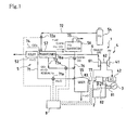
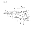
- Fig. 1 is a block diagram that shows an overall configuration of a power generating system that generates power with a gas engine 1 according to this embodiment.
- this gas engine 1 is configured so that an output shaft 21 that extends from an engine unit 2 is connected to a power generating device 3, and power is generated by the power generating device 3 with the rotational driving force of the output shaft 21.
- the air intake system of the gas engine 1 contains an air supply system 4 and a fuel supply system 5.
- a gaseous mixture of air supplied from the air supply system 4 and fuel supplied from the fuel supply system 5 is supplied to a combustion chamber not shown in the diagram of the engine unit 2, so that the engine unit 2 can drive.
- the following is an explanation of the air supply system 4 and the fuel supply system 5.
- the air supply system 4 is provided with a supercharger (compressor) 41 and an intercooler 42. Air is compressed by the supercharger 41, then this air is cooled by the intercooler 42, enabling high density air to be supplied to the combustion chamber. It should be noted that the supercharger 41 is directly coupled to an output shaft 62 of a turbine 61 provided at an exhaust tube 6 through which exhaust gas passes, and compresses air with the rotational output of the turbine 61.
- the fuel supply system 5 is provided with an exhaust heat boiler 52 as a means for producing water vapor, a transformer 57, a hydrogen tank 54, a mixer 55, and a hydrogen separating device 56 as a means for separating hydrogen.
- an exhaust heat boiler 52 as a means for producing water vapor
- a transformer 57 as a means for producing water vapor
- a hydrogen tank 54 as a means for producing water vapor
- a mixer 55 as a means for separating hydrogen.
- a transformational reaction H 2 + CO 2 ⁇ CO + H 2 O
- CO 2 carbon dioxide
- the thermal energy required for this transformational reaction is obtained from the exhaust gas that passes through the exhaust tube 6.
- Water is stored inside the exhaust heat boiler 52, and, by performing heat transfer between this water and the exhaust gas passing through the exhaust tube 6, water is vaporized to produce water vapor.
- the exhaust heat boiler 52 and the mixer 55 are connected by a water vapor supply tube 71, and the water vapor (H 2 O) produced inside the exhaust heat boiler 52 can be supplied to the inside of the mixer 55.
- the water vapor supply tube 71 is provided with an electrically-driven valve 71a that is aperture-adjustable.
- the transformer 57 causes the hydrogen and the carbon dioxide within itself to undergo a transformational reaction (H 2 + CO 2 ⁇ CO + H 2 O), changing the composition of the fuel.
- the transformer 57 is connected to the hydrogen tank 54 via a hydrogen supply tube 72, and the hydrogen stored inside the hydrogen tank 54 can be supplied to the inside of the transformer 57.
- the hydrogen supply tube 72 is provided with an electrically-driven valve 72a that is aperture-adjustable.
- the transformer 57 is connected to the mixer 55 by a transformed fuel supply tube 73, and the fuel (CO, H 2 O, and residual H 2 ) that has been transformed by the transformer 57 can be supplied to the inside of the mixer 55.
- the transformed fuel supply tube 73 is provided with an electrically-driven valve 73a that is aperture-adjustable. Additionally, a carbon dioxide supply tube 74 is connected to the transformer 57, and carbon dioxide (CO 2 ) can be supplied from, for example, a carbon dioxide tank that is not shown in the drawing.
- CO 2 carbon dioxide
- the hydrogen separating device 56 separates and extracts hydrogen (H 2 ) from fuel (C m H n , H 2 , CO, etc).
- An explicit configuration of the hydrogen separating device 56 is one provided with a built-in separation membrane and hydrogen adsorbing material, by which it is possible to separate and extract only hydrogen.
- separation membranes include palladium alloys, cellulose acetate membranes, polyimide, polyamide, porous polysulfone film/silicone, and so on.
- hydrogen absorbing alloys can be given as an example of hydrogen absorbing materials.
- carbon nanofibers, fullerene, multilayer fullerene, and other materials made from carbon molecules can be employed as a hydrogen absorbing material.
- the separation membrane and the hydrogen absorbing material are not limited to these, and it is possible to employ a variety of materials as long as the material can separate and extract hydrogen.
- the hydrogen separating device 56 is connected to the hydrogen tank 54 via a separated-hydrogen supply tube 75, and to the mixer 55 via a hydrogen-separated fuel supply tube 76.
- the hydrogen separating device 56 makes it possible to collect separated and extracted hydrogen (H 2 ) in the hydrogen tank 54, and to supply the hydrogen-separated fuel (C m H n ) to the mixer 55.
- the hydrogen-separated fuel supply tube 76 described above is provided with an electrically-driven valve 76a that is aperture-adjustable.
- the mixer 55 into which water vapor is supplied by the water vapor supply tube 71 and fuel is supplied by each of the fuel supply tubes 73 and 76, temporarily stores and mixes the water vapor and each fuel. After excess H 2 O is removed by a dehumidifier provided inside the mixer 55 but not shown in the drawing, fuel to which water vapor has been admixed is mixed with air through a mixed fuel supply tube 77 and supplied to the combustion chamber of the engine unit 2.
- a controller 8 is provided in the gas engine 1 to perform control for each portion.
- a plurality of sensors 81, 82, and 83 are connected to the controller 8, and each of the above-described electrically-driven valves 71a, 72a, 73a, and 76a performs aperture control upon reception of a detection signal from these sensors 81, 82, and 83.
- the sensors include: a load sensor 81 that detects the load of the power generating device 3, a knocking sensor 82 for measuring the knocking intensity of the engine unit 2, and a hydrogen concentration sensor 83 that measures the concentration of hydrogen components (the concentration of hydrogen components in the mixed fuel supply tube 77) in the fuel supplied from the mixer 55 to the engine unit 2.
- the water inside the exhaust heat boiler 52 is heated by the exhaust gas passing through the exhaust tube 6 and made into water vapor. Then, this water vapor is successively supplied to the mixer 55 by the water vapor supply tube 71.
- hydrogen is separated from hydrocarbon-based fuel by the hydrogen separating device 56.
- This separated hydrogen is collected at the hydrogen tank 54 via a separated-hydrogen supply tube 75, and the fuel from which hydrogen has been separated is supplied to the mixer 55 by the hydrogen-separated fuel supply tube 76.
- the fuel supplied to the mixer 55 by the hydrogen-separated fuel supply tube 76 has a reduced hydrogen concentration.
- the water vapor and each of the fuels that are supplied to the mixer 55 are mixed inside the mixer 55, then successively supplied to the combustion chamber of the engine unit 2 through the mixed fuel supply tube 77.
- the engine unit 2 is driven by the supply of this fuel, and power is generated from the drive of the power generating device 3 with the rotational drive of the output shaft 21.
- the amount of hydrogen components in the fuel is reduced by the transformational reaction inside the transformer 57, and the overall heat capacity of the fuel is increased with the mixing in of water vapor to the fuel. And, still more, the hydrogen concentration of the supplied fuel is reduced by hydrogen separation. This lowers the combustion velocity inside the combustion chamber, enabling the occurrence of backfiring to be inhibited. It also raises the methane number of the fuel, suppressing the occurrence of knocking. And, still more, it reduces the rate of heat generation, thus achieving improved engine thermal efficiency.
- Embodiment 2 the supply source is provided for supplying carbon dioxide to the transformer 57 is addressed more specifically.
- the rest of the configuration is the same as that described above in Embodiment 1. Consequently, only the points that differ from Embodiment 1 will be explained here.
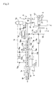
- Fig. 2 is a block diagram that shows an overall configuration of a power generating system that generates power with the gas engine 1 according to this embodiment (controller and sensors omitted).
- this gas engine 1 is provided with a CO 2 separating device 58 as a means for separating CO 2 .
- the CO 2 separating device 58 separates and extracts carbon dioxide from the exhaust gas that passes through the exhaust tube 6.
- a separation membrane is used in this configuration to separate and extract carbon dioxide.
- the CO 2 separating device 58 and the transformer 57 are connected by a carbon dioxide supply tube 74, and the carbon dioxide that is separated and extracted inside the CO 2 separating device 58 can be successively supplied to the transformer 57.
- the supply source for supplying hydrogen to the transformer 57 is the same hydrogen tank 54 as that in Embodiment 1, and hydrogen separated and extracted by the hydrogen separating device 56 is successively supplied to the hydrogen tank 54 via the separated-hydrogen supply tube 75.
- the separated-hydrogen supply tube 75 is provided with an electrically-driven valve 75a that is aperture-adjustable.
- Embodiment 3 a desulfurizing device and a fuel reforming device are provided. The rest of the configuration is the same as that described above in Embodiment 2. Consequently, only the points that differ from Embodiment 2 will be explained here.
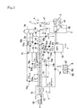
- Fig. 3 is a block diagram that shows an overall configuration of a power generating system that generates power with the gas engine 1 according to this embodiment.
- the gas engine 1 is provided with a desulfurizing device 53 and a fuel reforming device 51.
- the desulfurizing device 53 is for the purpose of removing the sulfur content contained in hydrocarbon-based fuels. That is, the catalysts of the fuel reforming device 51 (metals (Ni), alkaline carbonates (K 2 CO 3 ), basic oxides (CaO), minerals such as mineral coal (FeS 2 ) and so on) pose the risk of sulfur poisoning, and the desulfurizing device 53 is provided in order to avoid this. Furthermore, because a desulfurizing operation is carried out in the desulfurizing device 53 by hydrogenation-desulfurization, a hydrogen supply tube 78 for the purpose of desulfurization, and that is branched off from the hydrogen supply tube 72, is connected to the desulfurizing device 53.
- the hydrogen supply tube 78 for the purpose of desulfurization is provided with an electrically-driven valve 78a that is aperture-adjustable.
- a portion of the hydrogen inside the hydrogen tank 54 is supplied to the desulfurizing device 53 for the purpose of hydrogenation-desulfurization.
- a pre-reformed fuel supply tube 53a for supplying hydrocarbon-based fuel, and a desulfurnized fuel supply tube 53b for supplying desulfurnized fuel to the fuel reforming device 51 are connected to the desulfurizing device 53.
- the fuel reforming device 51 causes an endothermic reaction to occur within itself between water vapor and hydrocarbon-based fuel, thus performing a fuel-reforming operation.
- a branch tube 51a that branches off from the water vapor supply tube 71 is connected to the fuel reforming device 51.
- the branch tube 51a is provided with an electrically-driven valve 51b that is aperture-adjustable.
- the fuel reforming device 51 causes an endothermic reaction between the supplied water vapor and the hydrocarbon-based fuel supplied from the desulfurnized fuel supply tube 53b.
- a heat exchanging device that is not shown in the drawing is provided inside the fuel reforming device 51 in order to obtain thermal energy from the exhaust gas.
- the calorific value of the reformed fuel is greatly increased above that of the original hydrocarbon-based fuel, and this makes it possible to obtain a fuel that achieves improved thermal efficiency (power generator output/supplied fuel).
- the fuel reforming device 51 and the hydrogen separating device 56 are connected by a reformed fuel supply tube 56a, and the fuel that has been reformed by the fuel reforming device 51 is supplied to the hydrogen separating device 56.
- the fuel reforming device 51 is provided with a pressure-reducing mechanism that is capable of reducing the pressure inside the fuel reforming device 51.
- a pressure-reducing mechanism that is capable of reducing the pressure inside the fuel reforming device 51.
- a sufficient reforming reaction can be performed even if the temperature (exhaust gas temperature) of the heat source that heats the fuel reforming device 51 is comparatively low, thus making it possible to obtain a high conversion rate.
- Fig. 6(a) is a graph showing the relationship between the pressure inside the fuel reforming device 51 and the generated gas composition after a reforming reaction when methane gas is used as fuel.
- 6(b) is a graph showing the relationship between the pressure inside the fuel reforming device 51 and the proportion of unreformed methane when methane gas is used as fuel. As can be seen from these graphs, the lower the pressure inside the fuel reforming device 51, the better the reforming of the methane gas.
- a fuel with a high calorific value is obtained by reforming the hydrocarbon-based fuel, thus enabling improved thermal efficiency to be achieved for the engine. Furthermore, as it is possible to use fuels other than hydrocarbon-based fuels, it is possible to facilitate the realization of fuel diversification. In other words, it is possible to freely select hydrocarbon-based fuels and fuels other than hydrocarbon-based fuels for a gas engine of the same configuration, thus achieving wider versatility for gas engines.
- Embodiment 4 the fuel reforming device 51 and the hydrogen separating device 56 are integrally configured. The rest of the configuration is the same as that described above in Embodiment 3. Consequently, only the points that differ from Embodiment 3 will be explained here.
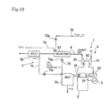
- Fig. 4 is a block diagram that shows an overall configuration of a power generating system that generates power with the gas engine 1 according to this embodiment.
- the fuel reforming device 51 and the hydrogen separating device 56 are an integrated construction in this gas engine 1. That is to say, the space inside the fuel reforming device 51 and the space inside the hydrogen separating device 56 are continuous, and the fuel reformed by the fuel reforming device 51 is supplied from the fuel reforming device 51 to the hydrogen separating device 56, and hydrogen is separated and extracted by the hydrogen separating device 56.
- the fuel reforming device 51 and the hydrogen separating device 56 do not need to be connected by piping, thus making it possible to achieve simplification of the manufacturing process for the gas engine 1, as well as enabling compactness for the engine 1 as a whole.
- Embodiment 5 an oxidation catalyst device and a hydrogen absorbing device are provided.
- the rest of the configuration is the same as that described above in Embodiment 4. Consequently, only the points that differ from Embodiment 4 will be explained here.
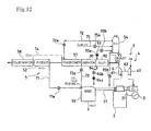
- Fig. 5 is a block diagram that shows an overall configuration of a power generating system that generates power with the gas engine 1 according to this embodiment. As the diagram shows, the gas engine 1 is provided with the oxidation catalyst device 91 and the hydrogen absorbing device 92.
- the oxidation catalyst device 91 combusts non-combusted components in the exhaust gas, and the temperatures inside the fuel reforming device 51 and the transformer 57 are raised above the temperature of the exhaust by this combustion. In other words, the temperatures inside the fuel reforming device 51 and the transformer 57 become higher, thus raising the temperature for the endothermic reaction that occurs in the fuel reforming device 51 and the temperature for the transformational reaction that occurs in the transformer 57 and promoting these reactions.
- the hydrogen absorbing device 92 contains a hydrogen absorbing material such as a hydrogen absorbing alloy. Furthermore, the hydrogen absorbing device 92 is connected to the hydrogen tank 54 by a hydrogen dispensing tube 93, and also connected to the mixer 55 by a first hydrogen supply tube 94. These tubes 93 and 94 are respectively provided with pumps 93a and 94a, and electrically-driven valves 93b and 94b, which are aperture-adjustable. Furthermore, heat is generated when the hydrogen absorbing material contained inside the hydrogen absorbing device 92 absorbs hydrogen and generates hydrides.
- the temperatures inside the fuel reforming device 51 and the transformer 57 are also raised by this generated heat, thus raising the temperature for the endothermic reaction that occurs in the fuel reforming device 51 and the temperature for the transformational reaction that occurs in the transformer 57, thus enabling these reactions to be promoted.
- Fig. 7 is a graph showing the relationship between the temperature inside the transformer 57 and the amount of CO produced in the transformational reaction in the transformer 57. As can be seen from this graph, the higher the temperature inside the transformer 57, the greater the amount of CO produced. That is, it can be seen that the transformational reaction is promoted.
- Fig. 8 is a graph showing the relationship between the atmospheric temperature (heat source temperature) inside the hydrogen absorbing device 92 when hydrogen is absorbed by the hydrogen absorbing material, and temperature rises (temperature rises brought about by the generation of heat in hydride generation).
- the higher the atmospheric temperature inside the hydrogen absorbing device 92 the higher the temperature rises, thus enabling promotion of the endothermic reaction in the fuel reforming device 51 and the transformational reaction in the transformer 57.
- the circle marks in Fig. 8 indicate the actual measured point of each type of hydrogen absorbing material, and the straight line is an approximation of the characteristics of hydrogen absorbing materials.
- Specific examples of these hydrogen absorbing materials include titanium and vanadium series metals with manganese additives, magnesium and nickel series metals, zeolites, hydrocarbons, benzenes, and the like, as well as the various materials described above.
- the hydrogen tank 54 and the mixer 55 are connected by a second hydrogen supply tube 95, enabling the hydrogen inside the hydrogen tank 54 to be supplied to the mixer 55.
- the second hydrogen supply tube 95 is provided with an electrically-driven valve 95b that is aperture-adjustable.
- one of the features for adjusting the amount of hydrogen supply in this embodiment is that hydrogen gas absorption and desorption are switchable in response to the temperature and pressure inside the hydrogen absorbing device 92.
- the gas engine in this embodiment is provided with an exhaust temperature sensor 84 that detects the temperature of the exhaust, and a pressure adjustment means not shown in the diagram for adjusting the pressure inside the hydrogen absorbing device 92.
- the temperature inside the hydrogen absorbing device 92 is governed by the temperature of the exhaust gas. In other words, the temperature inside the hydrogen absorbing device 92 can be obtained by detecting the temperature of the exhaust gas with the exhaust temperature sensor 84. As shown in Fig.
- the temperature inside the hydrogen absorbing device 92 changes with the temperature of the exhaust gas, which changes in response to the load on the engine.
- the pressure inside the hydrogen absorbing device 92 changes here in response to the fluctuating temperature inside the hydrogen absorbing device 92, and this enables control of the hydrogen absorption and hydrogen desorption of the hydrogen absorbing device 92.
- the pressure inside the hydrogen absorbing device 92 can be set comparatively high by the pressure adjustment means so that hydrogen absorption can be carried out.
- the temperature inside in the fuel reforming device 51 also rises due to the heat generated by hydride formation.
- the pressure inside the hydrogen absorbing device 92 can be set comparatively low by the pressure adjustment means so that hydrogen desorption can be carried out.
- hydrogen absorbing materials can be caused to absorb heat with the desorption of hydrogen in areas with comparatively low exhaust gas temperatures, and hydrogen absorbing materials can be caused to produce heat with the absorption of hydrogen in areas with comparatively high exhaust gas temperatures, thus functioning as a so-called chemical heat pump. In this way, it becomes possible to freely control hydrogen absorption and hydrogen desorption by causing the pressure inside the hydrogen absorbing device 92 to change in response to the exhaust gas temperature.
- the controller 8 is provided with an adjustment means 87 that enables free adjustments in the mixer 55 for the mixing proportions of hydrogen, transformed fuel, and hydrogen-separated reformed fuel.
- the adjustment means 87 adjusts the amount of transformed fuel supplied to the mixer 55 by adjusting the aperture of the electrically-driven valve 73a provided at the transformed fuel supply tube 73, and the amount of hydrogen supplied to the mixer 55 by controlling the pump 94a and adjusting the apertures of the electrically-driven valves 94b and 95b provided at the first and second hydrogen supply tubes 94 and 95, as well as the amount of hydrogen-separated reformed fuel supplied to the mixer 55 by adjusting the aperture of the electrically-driven valve 76a provided at the hydrogen-separated fuel supply tube 76. In this way, the mixing proportions of hydrogen, transformed fuel, and hydrogen-separated reformed fuel can be freely adjusted.
- controller 8 is provided with a hydrogen supply amount control means 85 and a mixing ratio adjustment means 86.
- the hydrogen supply amount control means 85 receives the output of the above-mentioned knocking sensor 82 and measures the knocking intensity, and, when a predetermined value of knocking intensity is exceeded, reduces the supply amount of hydrogen by reducing the apertures of the electrically-driven valves 94b and 95b of the first and second hydrogen supply tubes 94 and 95, thus lowering the mixing proportion of hydrogen in the total fuel.
- knocking when knocking is occurring, it is likely that the methane number has become too low due to the effect of hydrogen components in the supplied fuel, so knocking can be prevented in this situation by lowering the supply amount of hydrogen to raise the methane number.
- the mixing ratio adjustment means 86 receives the output of the above-mentioned hydrogen concentration sensor 83 and measures the mixing proportion of hydrogen in the total fuel, and adjusts the mixing proportions of the fuel and air that are supplied to the combustion chamber in response to the mixing proportion of hydrogen.
- the mixing proportion of hydrogen in the total fuel is identified in advance to enable favorable combustion in the combustion chamber with the minimum required supply amount of fuel for that mixing proportion of hydrogen, that is, the threshold limit for enabling lean combustion is obtained in accordance with the mixing proportion of hydrogen, and, based on that, the mixing proportion of fuel and air is adjusted. In this way, harmful substances in the exhaust gas of the gas engine 1 can be greatly reduced, and it is possible to achieve cleaner exhaust gases.
- Embodiments 6 to 8 use pure hydrogen gas as fuel.
- the gas engine of Embodiment 6 is the gas engine of Embodiment 1 applied as a pure hydrogen engine.
- the gas engine of Embodiment 7 is the gas engine of Embodiment 2 applied as a pure hydrogen engine.
- the gas engine of Embodiment 8 is the gas engine of Embodiment 5 applied as a pure hydrogen engine.
- the following explanations of these embodiments will concern the points that differ from the above-mentioned embodiments.
- the hydrogen separating device 56 of the gas engine of Embodiment 1 is eliminated in the gas engine 1 of this embodiment.
- this gas engine 1 water vapor produced by the exhaust heat boiler 52, and fuel formed by the mixer 57 are supplied to the mixer 55.
- the hydrogen separating device 56 of the gas engine of Embodiment 2 is eliminated in the gas engine of this embodiment.
- the gas engine 1 here is configured so that carbon dioxide in the exhaust gas that passes through the exhaust tube 6 is separated and extracted by the CO 2 separating device 58, and this carbon dioxide is successively supplied to the transformer 57.
- the hydrogen separating device 56, the fuel reforming device 51, and the desulfurizing device 53 of the gas engine of Embodiment 5 are eliminated in the gas engine of this embodiment.
- the reaction temperatures are raised by the oxidation catalyst device 91 and the hydrogen absorbing device 92 to achieve promotion of these reactions.
- gas engine 1 is not limited to being used for power generation, and the present invention can be made use of in gas engines used in various applications.
- the engine exhaust heat used by the fuel reforming device 51, the exhaust heat boiler 52, the transformer 57, and the hydrogen absorbing device 92 is not limited to the heat of exhaust gas, and the heat of engine coolants may also be used.
- the gas engine of the present invention can reduce the amount of hydrogen components in the supplied fuel by changing the composition of the fuel with a transformational reaction between hydrogen and carbon dioxide, or by separating hydrogen from the fuel, and it can increase the heat capacity of the fuel by supplying water vapor to the fuel supply system, thus reducing the combustion velocity, raising the methane number of the fuel, and keeping down the rate of heat produced.
- the problems of conventional gas engines namely backfiring, knocking, and low engine thermal efficiency, can be solved, thus achieving improvements in practicability for these engines.
- the transformational reaction and the reforming reaction can be caused to occur in a high-temperature environment, thus effectively achieving promotion of the reactions.
- each reaction can be caused to occur in a high-temperature environment even when the temperature of the exhaust gas is comparatively low, thus making it possible to achieve a high conversion rate.
- the fuel reforming device is configured to enable reduced internal pressure when reforming a hydrocarbon-based fuel, a sufficient reforming reaction can be performed even when the temperature of the heat source is comparatively low, and a high conversion rate can be obtained.
- the absorption and desorption of the hydrogen of the hydrogen absorbing material can be controlled easily even while effectively using the heat of the exhaust.
Landscapes
- Engineering & Computer Science (AREA)
- Chemical & Material Sciences (AREA)
- Combustion & Propulsion (AREA)
- Mechanical Engineering (AREA)
- General Engineering & Computer Science (AREA)
- Chemical Kinetics & Catalysis (AREA)
- General Chemical & Material Sciences (AREA)
- Oil, Petroleum & Natural Gas (AREA)
- Output Control And Ontrol Of Special Type Engine (AREA)
- Hydrogen, Water And Hydrids (AREA)
- Combined Controls Of Internal Combustion Engines (AREA)
- Electrical Control Of Air Or Fuel Supplied To Internal-Combustion Engine (AREA)
Abstract
A transformer (57) using exhaust gas heat as a heat source is
provided at a fuel supply system (5) of a gas engine (1), wherein the
transformer (57) causes a transformational reaction (H2 + CO2→ CO + H2O)
between hydrogen and carbon dioxide, thus changing the composition of the
fuel, and this fuel with a changed composition is supplied to a combustion
chamber. Furthermore, water vapor is produced by an exhaust heat boiler
(52) using exhaust gas heat as a heat source, and this water vapor is
supplied to a fuel supply system. Further still, a hydrogen separating
device (56) is provided that separates and extracts hydrogen from a fuel, and
the fuel is supplied to a combustion chamber after hydrogen is separated and
extracted.
Description
The present invention concerns gas engines that use fuels, such as
6C and 6B gases, containing a comparatively large proportion of hydrogen
components, and gas engines that use pure hydrogen as a fuel. In
particular, the present invention relates to measures for improving the
practicability of these types of gas engines.
Conventionally known as one type of gas engine are gas engines that
use gases such as 6C gas and 6B gas, which contain a comparatively large
proportion of hydrogen components, and that use pure hydrogen as a fuel.
Fig. 13 is a block diagram that shows an overall configuration of a
power generating system that generates power with this type of gas engine.
As the diagram shows, in this gas engine, an output shaft 131a that extends
from an engine unit 131 is connected to a power generating device 132, and
power is generated by the power generating device 132 using the rotational
driving force of the output shaft 131a.
Furthermore, the air intake system of the gas engine contains an air
supply system and a fuel supply system. A gaseous mixture of air supplied
from the air supply system and fuel supplied from the fuel supply system is
supplied to the combustion chamber so that the engine unit 131 is able to
drive.
The air supply system is provided with a supercharger (compressor)
133 and an intercooler 134. Air is compressed by the supercharger 133,
then this air is cooled by the intercooler 134, enabling high density air to be
supplied to the combustion chamber. It should be noted that the
supercharger c is directly coupled to an output shaft 136a of a turbine 136
provided at an exhaust tube 135 through which exhaust gas passes, and
compresses air with the rotational output of the turbine 136.
This gaseous mixture of air supplied from the air supply system and
fuel (hydrocarbon-based fuels, pure hydrogen, etc.) supplied from the fuel
supply system is supplied to the combustion chamber, and power is
generated by the power generating device 132 driven by the engine unit 131.
However, this type of gas engine has the following problems, and
sufficient practicability is yet to be achieved.
The inventors of the present invention studied the causes of these
drawbacks, and they found the presence of hydrogen components in fuels to
be a cause of these drawbacks.
In consideration of these points, the object of the present invention is
to present a gas engine that can prevent backfiring and knocking, and can
improve engine thermal efficiency.
In order to achieve the above-mentioned object, the present invention
lowers the combustion velocity, raises the methane number, and, further still,
keeps down the rate of heat generation by such operations as reducing the
amount of hydrogen components in a supplied fuel by changing the
composition of the fuel with a transformational reaction between hydrogen
and carbon dioxide, or by separating hydrogen from the fuel, and as
increasing the heat capacity of the fuel by supplying water vapor to the fuel
supply system.
The gas engine corresponding to claim 1 of the present invention
(hereafter "invention 1") assumes a gas engine that uses a fuel containing
hydrogen components. This gas engine is provided with a transformer that
uses engine exhaust heat as a heat source, wherein a transformational
reaction (H2 + CO2→ CO + H2O) between hydrogen and carbon dioxide is
caused to occur in the transformer, changing a composition of the fuel, and
the fuel with a changed composition is supplied to a combustion chamber.
The gas engine corresponding to claim 2 of the present invention
(hereafter "invention 2") is a gas engine that uses a fuel containing hydrogen
components, and is provided with a water vapor producing means for
producing water vapor using engine exhaust heat as a heat source, wherein
water vapor produced by the water vapor producing means is supplied to a
fuel supply system.
The gas engine corresponding to claim 3 of the present invention
(hereafter "invention 3") is a gas engine that uses a fuel containing hydrogen
components, and is provided with a hydrogen separating means for
separating and extracting hydrogen from the fuel, wherein a fuel from which
hydrogen has been separated and extracted by the hydrogen separating
means is supplied to a combustion chamber.
The gas engine corresponding to claim 4 of the present invention
(hereafter "invention 4") is a gas engine provided with at least two of the
configurations of inventions 1 to 3. That is, at least two of the following
operations are performed: a supply operation in which a fuel that has a
changed composition due to a transformational reaction using the
transformer of the gas engine according to invention 1 is supplied to a
combustion chamber, a supply operation in which water vapor that is
produced by the water vapor producing means in the gas engine according to
invention 2 is supplied to a fuel supply system, and a supply operation in
which a fuel from which hydrogen has been separated and extracted by the
hydrogen separating means in the gas engine according to invention 3 is
supplied to a combustion chamber.
In the above configurations, in invention 1, the amount of hydrogen
components in the fuel is reduced by a transformational reaction inside the
transformer, in invention 2, the heat capacity of the fuel is increased by the
admixture of water vapor, and in invention 3, the hydrogen concentration in
the supplied fuel is reduced. The results of this are that the combustion
velocity in the combustion chamber is lowered, thus enabling the occurrence
of backfiring to be inhibited, and the methane number of the fuel is raised,
thus enabling the occurrence of knocking to be suppressed (the methane
number of H2 is 0, and the methane number of CO is 73). Further still, the
rate of heat generation is reduced, thus improving engine thermal efficiency.
It should be noted that the influence and effect of these can be obtained
outstandingly in invention 4, which is configured as a combination of the
configurations in inventions 1 to 3.
The gas engine corresponding to claim 5 of the present invention
(hereafter "invention 5") is an explicit configuration for supplying carbon
dioxide to the transformer. In short, a configuration according to invention
1 or 4, wherein the engine exhaust system is provided with a CO2 separating
means, and wherein the carbon dioxide separated from the exhaust gas by
the CO2 separating means is supplied to the transformer.
The gas engine corresponding to claim 6 of the present invention
(hereafter "invention 6") is specifically configured for supplying carbon
dioxide to the transformer. In short, a configuration according to invention
1 or 4, provided with a hydrogen separating means for separating and
extracting hydrogen from a fuel, wherein the hydrogen separated by the
hydrogen separating means is supplied to the transformer.
The gas engine corresponding to claim 7 of the present invention
(hereafter "invention 7") is a gas engine in which the configurations of
inventions 5 and 6 are used together. That is, the following operations are
performed together: a supply operation in which carbon dioxide separated by
the CO2 separating means of the gas engine according to invention 5 is
supplied to the transformer, and a supply operation in which hydrogen
separated by a hydrogen separating means of the gas engine according to
invention 6 is supplied to the transformer.
With inventions 5 and 7, exhaust gas is used effectively so that a
transformational reaction can be caused in the transformer, thus there is no
need to provide a special supply source of carbon dioxide. Furthermore,
with inventions 6 and 7, hydrogen separated and extracted from the fuel is
used effectively so that a transformational reaction can be caused in the
transformer, thus there is no need to provide a special supply source of
hydrogen.
The gas engines corresponding to claims 8 to 10 of the present
invention (hereafter "inventions 8 to 10") are provided with an additional
means for reforming hydrocarbon-based fuels as a fuel. That is, invention 8
is a configuration according to any of the configurations of inventions 1, or 4
to 7, wherein the fuel is a hydrocarbon-based fuel, wherein the gas engine is
provided with a fuel reforming device that reforms fuel by using engine
exhaust heat to cause an endothermic reaction (CmHn + mH2O→ mCO +
(n/2 + m) H2) between water vapor and the fuel, and wherein a fuel reformed
by the fuel reforming device is supplied to a combustion chamber.
Furthermore, the gas engine corresponding to claim 9 of the present
invention (hereafter, "invention 9") is a gas engine according to the
configuration of invention 2, wherein the fuel is a hydrocarbon-based fuel,
wherein the gas engine comprises a fuel reforming device that reforms fuel
by using engine exhaust heat to cause an endothermic reaction (CmHn +
mH2O→ mCO + (n/2 + m) H2) between water vapor and the fuel, and
wherein a fuel reformed by the fuel reforming device is supplied to a
combustion chamber.
And further still, the gas engine corresponding to claim 10 of the
present invention (hereafter, "invention 10"), is a gas engine according to the
configuration of invention 3, wherein the fuel is a hydrocarbon-based fuel,
wherein the gas engine comprises a fuel reforming device that reforms fuel
by using engine exhaust heat to cause an endothermic reaction (CmHn +
mH2O→ mCO + (n/2 + m) H2) between water vapor and the fuel, and
wherein a fuel reformed by this fuel reforming device is supplied to a
combustion chamber.
With the configurations of inventions 8 to 10, it is possible to achieve
improvements in engine thermal efficiency by reforming the
hydrocarbon-based fuel. Furthermore, as it is possible to use fuels other
than hydrocarbon-based fuels, it is possible to facilitate fuel diversification.
In other words, it is possible to freely select hydrocarbon fuels and fuels
other than hydrocarbon fuels for a gas engine of the same configuration.
The gas engines corresponding to claims 11 and 12 of the present
invention (hereafter "invention 11" and "invention 12" respectively) relate to
improvement for configurations provided with the fuel reforming device
described above. That is, the configuration of invention 11 is a gas engine
according to the configuration of invention 1o, wherein the hydrogen
separating device and the fuel reforming device are integrally configured,
wherein, while hydrogen is separated and extracted by the hydrogen
separating means, a fuel reforming operation is performed by the fuel
reforming device. Furthermore, the configuration of invention 12 is a gas
engine according to the configuration of invention 8, wherein the hydrogen
separating means for separating and extracting hydrogen from the fuel, and
the fuel reforming device are integrally configured, wherein while hydrogen
is separated and extracted by the hydrogen separating means, a fuel
reforming operation is performed by the fuel reforming device. With these
configurations, the fuel reforming device and the hydrogen separating means
do not need to be connected by piping, thus enabling compactness for the
engine as a whole.
The gas engines corresponding to claims 13 to 20 of the present
invention (hereafter "inventions 13 to 20") relate to configurations for
achieving promotion of the transformational reaction or the endothermic
reaction (reforming reaction). That is, invention 13 is a configuration
according to any of the configurations of inventions 1, 4 to 7, 8 or 12, wherein
the temperature inside the transformer is raised by combusting a portion of
pre-transformation fuel or post-transformation fuel.
Invention 14 is a configuration according to the configuration of
invention 8 or 12, wherein the temperature inside the transformer is raised
by combusting a portion of pre-reforming fuel or post-reforming fuel.
The gas engine corresponding to claim 15 of the present invention
(hereafter, "invention 15"), is a gas engine according to any of the
configurations of inventions 8 to 12, wherein the temperature inside the fuel
reforming device is raised by combusting a portion of pre-reforming fuel or
post-reforming fuel.
The gas engine corresponding to claim 16 of the present invention
(hereafter, "invention 16"), is a gas engine according to the configurations of
either invention 8 or 12, wherein the temperature inside the fuel reforming
device is raised by combusting a portion of pre-transformation fuel or
post-transformation fuel.
The gas engine corresponding to claim 17 of the present invention
(hereafter, "invention 17"), is a gas engine according to any of the
configurations of inventions 1, 4 to 8, 12 to 14, or 16, provided with an
oxidation catalyst device that causes non-combusted components in exhaust
gas to be combusted, wherein the temperature inside the transformer is
raised above the temperature of the exhaust by the combustion of
non-combusted components with the oxidation catalyst device.
The gas engine corresponding to claim 18 of the present invention
(hereafter, "invention 18"), is a gas engine according to any of the
configurations of inventions 8 to 12, or 14 to 16, provided with an oxidation
catalyst device that causes non-combusted components in exhaust gas to be
combusted, wherein the temperature inside the fuel reforming device is
raised above the temperature of the exhaust by the combustion of
non-combusted components with the oxidation catalyst device.
The gas engine corresponding to claim 19 of the present invention
(hereafter, "invention 19"), is a gas engine according to any of the
configurations of inventions 1, 4 to 7, 8, 12 to 14, or 16, provided with a
hydrogen absorbing device that contains a hydrogen absorbing material and
is capable of absorbing hydrogen, wherein the temperature inside the
transformer is raised above the temperature of the exhaust by the heat
generated by hydride formation when the hydrogen absorbing material
absorbs hydrogen.
The gas engine corresponding to claim 20 of the present invention
(hereafter, "invention 20"), is a gas engine according to any of the
configurations of inventions 8 to 12, or 14 to 16, provided with a hydrogen
absorbing device that contains a hydrogen absorbing material and is capable
of absorbing hydrogen, wherein the temperature inside the fuel reforming
device is raised above the temperature of the exhaust by the heat generated
by hydride formation when the hydrogen absorbing material absorbs
hydrogen.
With these specified items, the transformational reaction and the
reforming reaction can be caused to occur in a high-temperature
environment, thus effectively achieving promotion of the reactions. For
example, a transformational reaction or a reforming reaction generally
requires a temperature above 700°C. When using exhaust gas as the heat
source for the reactions, each reaction can be caused to occur in a
high-temperature environment, even when the temperature of the exhaust
gas is less than 700°C, thus making it possible to achieve a high conversion
rate.
The gas engine corresponding to claim 21 of the present invention
(hereafter, "invention 21"), is a gas engine according to any of the
configurations of inventions 8 to 12, 14 to 16, 18, or 20, wherein the pressure
inside the fuel reforming device can be reduced when a hydrocarbon-based
fuel is reformed. When the internal pressure of the fuel reforming device is
set low, a sufficient reforming reaction can be carried out even with a
comparatively low temperature (exhaust temperature) of the heat source
that heats the fuel reforming device, and a high conversion rate can be
obtained.
The gas engine corresponding to claim 22 of the present invention
(hereafter, "invention 22"), is a gas engine in which configurations of
inventions 13 to 21 are used together. That is, at least two of the following
operations are performed: a temperature-raising operation in which the
temperature inside the transformer is raised by combusting a portion of
pre-transformation fuel or post-transformation fuel in the gas engine
according to invention 13, a temperature-raising operation in which the
temperature inside the transformer is raised by combusting a portion of
pre-reforming fuel or post-reforming fuel in the gas engine according to
invention 14, a temperature-raising operation in which the temperature
inside the fuel reforming device is raised by combusting a portion of
pre-reforming fuel or post-reforming fuel in the gas engine according to
invention 15, a temperature-raising operation in which the temperature
inside the fuel reforming device is raised by combusting a portion of
pre-transformation fuel or post-transformation fuel in the gas engine
according to invention 16, a temperature-raising operation in which the
temperature inside the transformer is raised by the combustion of
non-combusted components by the oxidation catalyst device in the gas engine
according to invention 17, a temperature-raising operation in which the
temperature inside the fuel reforming device is raised by the combustion of
non-combusted components by the oxidation catalyst device in the gas engine
according to invention 18, a temperature-raising operation in which the
temperature inside the transformer is raised by the heat generated by
hydride formation when the hydrogen absorbing material absorbs hydrogen
in the gas engine according to invention 19, a temperature-raising operation
in which the temperature inside the fuel reforming device is raised by the
heat generated by hydride formation when the hydrogen absorbing material
absorbs hydrogen in the gas engine according to invention 20, or a
pressure-reducing operation in which the pressure inside the fuel reforming
device is reduced in the gas engine according to invention 21. In this way,
when employing any of the configurations of inventions 13 to 20, the
transformational reaction or the reforming reaction can be caused to occur in
a high-temperature environment, thus effectively achieving promotion of the
reactions. Furthermore, if these inventions are used together, it becomes
possible to cause the reactions to occur with a high conversion rate even
when, for example, the temperature of the exhaust is less than 600°C. Also,
a high conversion rate can also be obtained when employing the
configuration of invention 21.
The gas engine corresponding to claim 23 of the present invention
(hereafter, "invention 23"), is a gas engine according to any of the
configurations of inventions 19, 20, or 22, provided with a tank that stores
hydrogen, wherein the hydrogen inside the tank is absorbed by the hydrogen
absorbing material inside the hydrogen absorbing device, and hydrogen is
drawn from the hydrogen absorbing device using engine exhaust heat and
supplied to a combustion chamber. With this configuration, hydrogen can
be stored stably in the hydrogen absorbing device and hydrogen can be
supplied stably from this hydrogen absorbing device to a combustion
chamber.
The gas engine corresponding to claim 24 of the present invention
(hereafter, "invention 24"), is a gas engine according to any of the
configurations of inventions 19, 20, or 22, provided with a tank that stores
hydrogen, wherein the hydrogen inside the tank is absorbed by the hydrogen
absorbing material inside the hydrogen absorbing device on the one hand, an
exhaust temperature sensor that detects the temperature of the exhaust,
and a pressure adjustment means for adjusting the pressure inside the
hydrogen absorbing device. And, wherein, based on the exhaust temperature
detected by the exhaust temperature sensor, the pressure adjustment means
adjusts the pressure inside the hydrogen absorbing device, and controls the
formation of hydrides of hydrogen and the hydrogen absorbing material, and
the separation of hydrogen from the hydrogen absorbing material. With
this configuration, it becomes possible to freely control the absorption and
desorption of hydrogen of the hydrogen absorbing materials while effectively
using the exhaust heat.
The gas engine corresponding to claim 25 of the present invention
(hereafter "invention 25") is a gas engine in which the configurations of
inventions 23 and 24 are used together. That is, the following operations
are performed together: a supply operation in which hydrogen drawn from
the hydrogen absorbing device is supplied to a combustion chamber in the
gas engine according to invention 23, and a control operation in which the
formation of hydrides of hydrogen and the hydrogen absorbing material, and
the separation of hydrogen from the hydrogen absorbing material is
controlled by adjusting the pressure inside the hydrogen absorbing device in
the gas engine according to invention 24.
As for the gas engines corresponding to claims 26 and 27 of the
present invention (hereafter "invention 26" and "invention 27" respectively),
the configurations of invention 26 and invention 27 relate to improvements
in the transformer and the fuel reforming device in consideration of starting
ability and load responsiveness. That is, the configuration of invention 26
is a gas engine according to any of the inventions 1, 4 to 8, 12 to 14, 16, 17, 19,
or 22, provided with a mixer that mixes hydrogen and post-transformation
fuel, and an adjustment means capable of freely adjusting the mixing
proportions in the mixer of hydrogen and post-transformation fuel.
Furthermore, the configuration of invention 27 is a gas engine
according to any of the inventions 8 to 12, 14 to 16, 18, or 20 to 22, provided
with a mixer that mixes hydrogen and hydrogen-separated reformed fuel,
and an adjustment means capable of freely adjusting the mixing proportions
in the mixer of hydrogen and hydrogen-separated reformed fuel.
With these specified items, the startup time required until the
transformer and the fuel reforming device start operation can be shortened,
thus improving responsiveness at the times of load input and load cutoff.
The gas engine corresponding to claim 28 of the present invention
(hereafter "invention 28") is configured to achieve an enlarged scope of usage
for the hydrogen separated and extracted by the hydrogen separating means.
That is, the configuration of invention 28 is a gas engine according to any of
the inventions 10 to 12, provided with a desulfurizing device that removes
sulfur content contained in a fuel by hydrogenation-desulfurization, wherein
a portion of the hydrogen separated and extracted by the hydrogen
separating means is supplied to the desulfurizing device.
With this specified item, the hydrogen separated and extracted by
the hydrogen separating means can also be used for the
hydrogenation-desulfurization of the desulfurizing device. Conventionally,
a hydrogen tank was provided in order to supply the hydrogen used for the
hydrogenation-desulfurization, and it was necessary to replace or refill with
hydrogen the hydrogen tank when it tank became empty. With this
configuration, this hydrogen tank is not required, so there is no need for the
tasks of replacement or hydrogen refilling.
The gas engine corresponding to claim 29 of the present invention
(hereafter "invention 29") is a gas engine in which the operation of supplying
hydrogen is explicitly specified. That is, the configuration of invention 29 is
a gas engine according to any of the inventions 1 or 3 to 28, provided with a
knocking sensor that detects an occurrence of knocking, and a hydrogen
supply amount control means that receives output from the knocking sensor
and measures the knocking intensity, and, when a predetermined value of
knocking intensity is exceeded, reduces the mixing proportion of hydrogen in
the total fuel supplied to the combustion chamber.
A condition in which knocking occurs is when the methane number
becomes too low due to the influence of hydrogen components in the supplied
fuel. For this reason, it is effective to reduce the supply amount of hydrogen
in this condition to increase the methane number and prevent knocking.
That is, the hydrogen supply amount control means receives output from the
knocking sensor and measures the knocking intensity, and when an
occurrence of knocking is detected or predicted, the mixing proportion of
hydrogen in the total fuel supplied can be reduced. In this way, the
methane number of the supplied fuel is increased, and the occurrence of
knocking can be avoided.
The gas engine corresponding to claim 30 of the present invention
(hereafter "invention 30") is a gas engine in which the operation of adjusting
the mixing proportions of hydrogen and hydrogen-separated reformed fuel is
explicitly specified. That is, the configuration of invention 30 is a gas
engine according to any of the inventions 10 to 12, 28, or 29, provided with a
mixing ratio adjustment means for adjusting the mixing proportions of
hydrogen and hydrogen-separated reformed fuel. In order to reduce
harmful substances, namely NOx, CO, and HC, in the exhaust gas as much
as possible, it is preferable to perform lean combustion. For this reason, the
mixing ratio adjustment means identifies in advance the mixing proportion
of hydrogen in the total fuel, and in order to enable favorable combustion in
the combustion chamber with the minimum required supply amount of fuel
for that mixing proportion of hydrogen, it obtains the threshold limit for
enabling lean combustion in accordance with the mixing proportion of
hydrogen, and, based on that, adjusts the above-described mixing proportion.
In this way, the engine can be operated with lean combustion, and harmful
substances in the exhaust gas can be reduced.
The gas engine corresponding to claim 31 of the present invention
(hereafter "invention 31") is a gas engine in which pure hydrogen is made
use of as a fuel in the above-described gas engines.
Referring to the accompanying drawings, the following is an
explanation of embodiments of the present invention. Respective
explanations will be given here for several embodiments in which 6C gas (a
fuel containing a comparatively large proportion of hydrogen components) is
used as fuel, and for several embodiments in which pure hydrogen gas is
used as fuel. Furthermore, the gas engine in each embodiment uses the
output therein for power generation.
Fig. 1 is a block diagram that shows an overall configuration of a
power generating system that generates power with a gas engine 1 according
to this embodiment. As the diagram shows, this gas engine 1 is configured
so that an output shaft 21 that extends from an engine unit 2 is connected to
a power generating device 3, and power is generated by the power generating
device 3 with the rotational driving force of the output shaft 21.
Furthermore, the air intake system of the gas engine 1 contains an
air supply system 4 and a fuel supply system 5. A gaseous mixture of air
supplied from the air supply system 4 and fuel supplied from the fuel supply
system 5 is supplied to a combustion chamber not shown in the diagram of
the engine unit 2, so that the engine unit 2 can drive. The following is an
explanation of the air supply system 4 and the fuel supply system 5.
The air supply system 4 is provided with a supercharger (compressor)
41 and an intercooler 42. Air is compressed by the supercharger 41, then
this air is cooled by the intercooler 42, enabling high density air to be
supplied to the combustion chamber. It should be noted that the
supercharger 41 is directly coupled to an output shaft 62 of a turbine 61
provided at an exhaust tube 6 through which exhaust gas passes, and
compresses air with the rotational output of the turbine 61.
On the other hand, the fuel supply system 5 is provided with an
exhaust heat boiler 52 as a means for producing water vapor, a transformer
57, a hydrogen tank 54, a mixer 55, and a hydrogen separating device 56 as a
means for separating hydrogen. At the fuel supply system 5, a
transformational reaction (H2 + CO2 → CO + H2O) between hydrogen (H2)
and carbon dioxide (CO2) is caused, changing the composition of the fuel, and
this fuel with a changed composition is supplied to the combustion chamber
of the engine unit 2. Furthermore, the thermal energy required for this
transformational reaction is obtained from the exhaust gas that passes
through the exhaust tube 6. The following is an explanation of the elements
that constitute the fuel supply system 5.
Water is stored inside the exhaust heat boiler 52, and, by performing
heat transfer between this water and the exhaust gas passing through the
exhaust tube 6, water is vaporized to produce water vapor. The exhaust
heat boiler 52 and the mixer 55 are connected by a water vapor supply tube
71, and the water vapor (H2O) produced inside the exhaust heat boiler 52 can
be supplied to the inside of the mixer 55. Furthermore, the water vapor
supply tube 71 is provided with an electrically-driven valve 71a that is
aperture-adjustable.
The transformer 57 causes the hydrogen and the carbon dioxide
within itself to undergo a transformational reaction (H2 + CO2→ CO + H2O),
changing the composition of the fuel. The transformer 57 is connected to
the hydrogen tank 54 via a hydrogen supply tube 72, and the hydrogen
stored inside the hydrogen tank 54 can be supplied to the inside of the
transformer 57. Furthermore, the hydrogen supply tube 72 is provided
with an electrically-driven valve 72a that is aperture-adjustable.
Additionally, the transformer 57 is connected to the mixer 55 by a
transformed fuel supply tube 73, and the fuel (CO, H2O, and residual H2)
that has been transformed by the transformer 57 can be supplied to the
inside of the mixer 55. Furthermore, the transformed fuel supply tube 73 is
provided with an electrically-driven valve 73a that is aperture-adjustable.
Additionally, a carbon dioxide supply tube 74 is connected to the transformer
57, and carbon dioxide (CO2) can be supplied from, for example, a carbon
dioxide tank that is not shown in the drawing.
The hydrogen separating device 56 separates and extracts hydrogen
(H2) from fuel (CmHn, H2, CO, etc). An explicit configuration of the
hydrogen separating device 56 is one provided with a built-in separation
membrane and hydrogen adsorbing material, by which it is possible to
separate and extract only hydrogen. Examples of separation membranes
include palladium alloys, cellulose acetate membranes, polyimide, polyamide,
porous polysulfone film/silicone, and so on. And hydrogen absorbing alloys
can be given as an example of hydrogen absorbing materials. Furthermore,
carbon nanofibers, fullerene, multilayer fullerene, and other materials made
from carbon molecules can be employed as a hydrogen absorbing material.
It should be noted that the separation membrane and the hydrogen
absorbing material are not limited to these, and it is possible to employ a
variety of materials as long as the material can separate and extract
hydrogen. Furthermore, the hydrogen separating device 56 is connected to
the hydrogen tank 54 via a separated-hydrogen supply tube 75, and to the
mixer 55 via a hydrogen-separated fuel supply tube 76. In short, the
hydrogen separating device 56 makes it possible to collect separated and
extracted hydrogen (H2) in the hydrogen tank 54, and to supply the
hydrogen-separated fuel (CmHn) to the mixer 55. The hydrogen-separated
fuel supply tube 76 described above is provided with an electrically-driven
valve 76a that is aperture-adjustable.
The mixer 55, into which water vapor is supplied by the water vapor
supply tube 71 and fuel is supplied by each of the fuel supply tubes 73 and 76,
temporarily stores and mixes the water vapor and each fuel. After excess
H2O is removed by a dehumidifier provided inside the mixer 55 but not
shown in the drawing, fuel to which water vapor has been admixed is mixed
with air through a mixed fuel supply tube 77 and supplied to the combustion
chamber of the engine unit 2.
Furthermore, a controller 8 is provided in the gas engine 1 to perform
control for each portion. A plurality of sensors 81, 82, and 83 are connected
to the controller 8, and each of the above-described electrically-driven valves
71a, 72a, 73a, and 76a performs aperture control upon reception of a
detection signal from these sensors 81, 82, and 83. Examples of the sensors
include: a load sensor 81 that detects the load of the power generating device
3, a knocking sensor 82 for measuring the knocking intensity of the engine
unit 2, and a hydrogen concentration sensor 83 that measures the
concentration of hydrogen components (the concentration of hydrogen
components in the mixed fuel supply tube 77) in the fuel supplied from the
mixer 55 to the engine unit 2. The above has been an explanation of the
configuration of the gas engine 1.
The following is an explanation of the operations of the
thus-configured gas engine 1. These operations are performed when the
electrically-driven valves 71a, 72a, 73a, and 76a are all in an open state.
First, the water inside the exhaust heat boiler 52 is heated by the
exhaust gas passing through the exhaust tube 6 and made into water vapor.
Then, this water vapor is successively supplied to the mixer 55 by the water
vapor supply tube 71.
At the same time, hydrogen gas from the hydrogen supply tube 72,
and carbon dioxide from the carbon dioxide supply tube 74 are supplied to
the inside of the transformer 57. Furthermore, the inside of the
transformer 57 is heated by the exhaust gas passing through the exhaust
tube 6. This causes the hydrogen and carbon dioxide to undergo a
transformational reaction (H2 + CO2→ CO + H2O) inside the transformer 57,
changing the composition of the fuel. This transformed fuel is supplied to
the inside of the mixer 55 by the transformed fuel supply tube 73. In short,
a fuel with a reduced amount of hydrogen components is produced by this
transformational reaction, and this fuel is supplied to the inside of the mixer
55.
Furthermore, hydrogen is separated from hydrocarbon-based fuel by
the hydrogen separating device 56. This separated hydrogen is collected at
the hydrogen tank 54 via a separated-hydrogen supply tube 75, and the fuel
from which hydrogen has been separated is supplied to the mixer 55 by the
hydrogen-separated fuel supply tube 76. In short, the fuel supplied to the
mixer 55 by the hydrogen-separated fuel supply tube 76 has a reduced
hydrogen concentration.
In this way, the water vapor and each of the fuels that are supplied to
the mixer 55 are mixed inside the mixer 55, then successively supplied to the
combustion chamber of the engine unit 2 through the mixed fuel supply tube
77. At this point, because the fuel has water vapor mixed in, the overall
heat capacity of the fuel is comparatively high. The engine unit 2 is driven
by the supply of this fuel, and power is generated from the drive of the power
generating device 3 with the rotational drive of the output shaft 21.
In this way, in this embodiment, the amount of hydrogen components
in the fuel is reduced by the transformational reaction inside the transformer
57, and the overall heat capacity of the fuel is increased with the mixing in of
water vapor to the fuel. And, still more, the hydrogen concentration of the
supplied fuel is reduced by hydrogen separation. This lowers the
combustion velocity inside the combustion chamber, enabling the occurrence
of backfiring to be inhibited. It also raises the methane number of the fuel,
suppressing the occurrence of knocking. And, still more, it reduces the rate
of heat generation, thus achieving improved engine thermal efficiency.
The following is an explanation of Embodiment 2. In this
embodiment, the supply source is provided for supplying carbon dioxide to
the transformer 57 is addressed more specifically. The rest of the
configuration is the same as that described above in Embodiment 1.
Consequently, only the points that differ from Embodiment 1 will be
explained here.
Fig. 2 is a block diagram that shows an overall configuration of a
power generating system that generates power with the gas engine 1
according to this embodiment (controller and sensors omitted). As the
diagram shows, this gas engine 1 is provided with a CO2 separating device 58
as a means for separating CO2. The CO2 separating device 58 separates
and extracts carbon dioxide from the exhaust gas that passes through the
exhaust tube 6. As in the hydrogen separating device 56, a separation
membrane is used in this configuration to separate and extract carbon
dioxide. Furthermore, the CO2 separating device 58 and the transformer 57
are connected by a carbon dioxide supply tube 74, and the carbon dioxide
that is separated and extracted inside the CO2 separating device 58 can be
successively supplied to the transformer 57.
Furthermore, the supply source for supplying hydrogen to the
transformer 57 is the same hydrogen tank 54 as that in Embodiment 1, and
hydrogen separated and extracted by the hydrogen separating device 56 is
successively supplied to the hydrogen tank 54 via the separated-hydrogen
supply tube 75. It should be noted that, the separated-hydrogen supply
tube 75 is provided with an electrically-driven valve 75a that is
aperture-adjustable.
With this embodiment, carbon dioxide separated and extracted from
the exhaust gas is used effectively so that a transformational reaction can be
caused in the transformer 57, thus there is no need to provide a special
supply source of carbon dioxide. Furthermore, hydrogen separated and
extracted from the fuel is used effectively so that a transformational reaction
can be caused in the transformer 57, thus there is no need to provide a
special supply source of hydrogen. For this reason, tasks such as replacing
the supply sources of carbon dioxide and hydrogen, and the tasks of filling
these gases, become unnecessary, thus making it possible to achieve
improved maintainability.
The following is an explanation of Embodiment 3. In this
embodiment, a desulfurizing device and a fuel reforming device are provided.
The rest of the configuration is the same as that described above in
Embodiment 2. Consequently, only the points that differ from Embodiment
2 will be explained here.
Fig. 3 is a block diagram that shows an overall configuration of a
power generating system that generates power with the gas engine 1
according to this embodiment. As the diagram shows, the gas engine 1 is
provided with a desulfurizing device 53 and a fuel reforming device 51.
The desulfurizing device 53 is for the purpose of removing the sulfur
content contained in hydrocarbon-based fuels. That is, the catalysts of the
fuel reforming device 51 (metals (Ni), alkaline carbonates (K2CO3), basic
oxides (CaO), minerals such as mineral coal (FeS2) and so on) pose the risk of
sulfur poisoning, and the desulfurizing device 53 is provided in order to avoid
this. Furthermore, because a desulfurizing operation is carried out in the
desulfurizing device 53 by hydrogenation-desulfurization, a hydrogen supply
tube 78 for the purpose of desulfurization, and that is branched off from the
hydrogen supply tube 72, is connected to the desulfurizing device 53. The
hydrogen supply tube 78 for the purpose of desulfurization is provided with
an electrically-driven valve 78a that is aperture-adjustable. In other words,
a portion of the hydrogen inside the hydrogen tank 54 is supplied to the
desulfurizing device 53 for the purpose of hydrogenation-desulfurization.
Additionally, a pre-reformed fuel supply tube 53a for supplying
hydrocarbon-based fuel, and a desulfurnized fuel supply tube 53b for
supplying desulfurnized fuel to the fuel reforming device 51 are connected to
the desulfurizing device 53.
The fuel reforming device 51 causes an endothermic reaction to occur
within itself between water vapor and hydrocarbon-based fuel, thus
performing a fuel-reforming operation. In short, a branch tube 51a that
branches off from the water vapor supply tube 71 is connected to the fuel
reforming device 51. The branch tube 51a is provided with an
electrically-driven valve 51b that is aperture-adjustable. Moreover, the fuel
reforming device 51 causes an endothermic reaction between the supplied
water vapor and the hydrocarbon-based fuel supplied from the desulfurnized
fuel supply tube 53b. Furthermore, a heat exchanging device that is not
shown in the drawing is provided inside the fuel reforming device 51 in order
to obtain thermal energy from the exhaust gas. This enables the
endothermic reaction (CmHn + mH2O→ mCO + (n/2 + m) H2) to occur within
the fuel reforming device 51 in an environment of a predetermined
temperature (with the temperature of exhaust gas, approximately 600°C for
example).
By carrying out a reaction such as this, the calorific value of the
reformed fuel is greatly increased above that of the original
hydrocarbon-based fuel, and this makes it possible to obtain a fuel that
achieves improved thermal efficiency (power generator output/supplied fuel).
Moreover, the fuel reforming device 51 and the hydrogen separating
device 56 are connected by a reformed fuel supply tube 56a, and the fuel that
has been reformed by the fuel reforming device 51 is supplied to the
hydrogen separating device 56.
Furthermore, although not shown in the diagram, the fuel reforming
device 51 is provided with a pressure-reducing mechanism that is capable of
reducing the pressure inside the fuel reforming device 51. By reducing the
pressure inside the fuel reforming device 51, a sufficient reforming reaction
can be performed even if the temperature (exhaust gas temperature) of the
heat source that heats the fuel reforming device 51 is comparatively low,
thus making it possible to obtain a high conversion rate. Fig. 6(a) is a graph
showing the relationship between the pressure inside the fuel reforming
device 51 and the generated gas composition after a reforming reaction when
methane gas is used as fuel. Fig. 6(b) is a graph showing the relationship
between the pressure inside the fuel reforming device 51 and the proportion
of unreformed methane when methane gas is used as fuel. As can be seen
from these graphs, the lower the pressure inside the fuel reforming device 51,
the better the reforming of the methane gas.
With the configuration of this embodiment, a fuel with a high
calorific value is obtained by reforming the hydrocarbon-based fuel, thus
enabling improved thermal efficiency to be achieved for the engine.
Furthermore, as it is possible to use fuels other than hydrocarbon-based
fuels, it is possible to facilitate the realization of fuel diversification. In
other words, it is possible to freely select hydrocarbon-based fuels and fuels
other than hydrocarbon-based fuels for a gas engine of the same
configuration, thus achieving wider versatility for gas engines.
The following is an explanation of Embodiment 4. In this
embodiment, the fuel reforming device 51 and the hydrogen separating
device 56 are integrally configured. The rest of the configuration is the
same as that described above in Embodiment 3. Consequently, only the
points that differ from Embodiment 3 will be explained here.
Fig. 4 is a block diagram that shows an overall configuration of a
power generating system that generates power with the gas engine 1
according to this embodiment. As the diagram shows, the fuel reforming
device 51 and the hydrogen separating device 56 are an integrated
construction in this gas engine 1. That is to say, the space inside the fuel
reforming device 51 and the space inside the hydrogen separating device 56
are continuous, and the fuel reformed by the fuel reforming device 51 is
supplied from the fuel reforming device 51 to the hydrogen separating device
56, and hydrogen is separated and extracted by the hydrogen separating
device 56.
With the configuration of this embodiment, the fuel reforming device
51 and the hydrogen separating device 56 do not need to be connected by
piping, thus making it possible to achieve simplification of the
manufacturing process for the gas engine 1, as well as enabling compactness
for the engine 1 as a whole.
The following is an explanation of Embodiment 5. In this
embodiment, an oxidation catalyst device and a hydrogen absorbing device
are provided. The rest of the configuration is the same as that described
above in Embodiment 4. Consequently, only the points that differ from
Embodiment 4 will be explained here.
Fig. 5 is a block diagram that shows an overall configuration of a
power generating system that generates power with the gas engine 1
according to this embodiment. As the diagram shows, the gas engine 1 is
provided with the oxidation catalyst device 91 and the hydrogen absorbing
device 92.
The oxidation catalyst device 91 combusts non-combusted
components in the exhaust gas, and the temperatures inside the fuel
reforming device 51 and the transformer 57 are raised above the
temperature of the exhaust by this combustion. In other words, the
temperatures inside the fuel reforming device 51 and the transformer 57
become higher, thus raising the temperature for the endothermic reaction
that occurs in the fuel reforming device 51 and the temperature for the
transformational reaction that occurs in the transformer 57 and promoting
these reactions.
The hydrogen absorbing device 92 contains a hydrogen absorbing
material such as a hydrogen absorbing alloy. Furthermore, the hydrogen
absorbing device 92 is connected to the hydrogen tank 54 by a hydrogen
dispensing tube 93, and also connected to the mixer 55 by a first hydrogen
supply tube 94. These tubes 93 and 94 are respectively provided with
pumps 93a and 94a, and electrically-driven valves 93b and 94b, which are
aperture-adjustable. Furthermore, heat is generated when the hydrogen
absorbing material contained inside the hydrogen absorbing device 92
absorbs hydrogen and generates hydrides. The temperatures inside the
fuel reforming device 51 and the transformer 57 are also raised by this
generated heat, thus raising the temperature for the endothermic reaction
that occurs in the fuel reforming device 51 and the temperature for the
transformational reaction that occurs in the transformer 57, thus enabling
these reactions to be promoted.
Fig. 7 is a graph showing the relationship between the temperature
inside the transformer 57 and the amount of CO produced in the
transformational reaction in the transformer 57. As can be seen from this
graph, the higher the temperature inside the transformer 57, the greater the
amount of CO produced. That is, it can be seen that the transformational
reaction is promoted.
Fig. 8 is a graph showing the relationship between the atmospheric
temperature (heat source temperature) inside the hydrogen absorbing device
92 when hydrogen is absorbed by the hydrogen absorbing material, and
temperature rises (temperature rises brought about by the generation of
heat in hydride generation). In this way, the higher the atmospheric
temperature inside the hydrogen absorbing device 92, the higher the
temperature rises, thus enabling promotion of the endothermic reaction in
the fuel reforming device 51 and the transformational reaction in the
transformer 57. It should be noted that the circle marks in Fig. 8 indicate
the actual measured point of each type of hydrogen absorbing material, and
the straight line is an approximation of the characteristics of hydrogen
absorbing materials. Specific examples of these hydrogen absorbing
materials include titanium and vanadium series metals with manganese
additives, magnesium and nickel series metals, zeolites, hydrocarbons,
benzenes, and the like, as well as the various materials described above.
Furthermore, in the gas engine 1 of this embodiment, the hydrogen
tank 54 and the mixer 55 are connected by a second hydrogen supply tube 95,
enabling the hydrogen inside the hydrogen tank 54 to be supplied to the
mixer 55. The second hydrogen supply tube 95 is provided with an
electrically-driven valve 95b that is aperture-adjustable.
With this configuration, two routes are secured as hydrogen supply
routes to the mixer 55: the route from the hydrogen absorbing device 92
through the first hydrogen supply tube 94, and the route from the hydrogen
tank 54 through the second hydrogen supply tube 95. With this
embodiment, hydrogen can be supplied to the mixer 55 in this manner.
Also, one of the features for adjusting the amount of hydrogen supply
in this embodiment is that hydrogen gas absorption and desorption are
switchable in response to the temperature and pressure inside the hydrogen
absorbing device 92. The following is a specific explanation of this. The
gas engine in this embodiment is provided with an exhaust temperature
sensor 84 that detects the temperature of the exhaust, and a pressure
adjustment means not shown in the diagram for adjusting the pressure
inside the hydrogen absorbing device 92. The temperature inside the
hydrogen absorbing device 92 is governed by the temperature of the exhaust
gas. In other words, the temperature inside the hydrogen absorbing device
92 can be obtained by detecting the temperature of the exhaust gas with the
exhaust temperature sensor 84. As shown in Fig. 9, the temperature inside
the hydrogen absorbing device 92 changes with the temperature of the
exhaust gas, which changes in response to the load on the engine. The
pressure inside the hydrogen absorbing device 92 changes here in response
to the fluctuating temperature inside the hydrogen absorbing device 92, and
this enables control of the hydrogen absorption and hydrogen desorption of
the hydrogen absorbing device 92. Specifically, in areas with comparatively
high exhaust gas temperatures (areas A in the diagram), the pressure inside
the hydrogen absorbing device 92 can be set comparatively high by the
pressure adjustment means so that hydrogen absorption can be carried out.
When this happens, the temperature inside in the fuel reforming device 51
also rises due to the heat generated by hydride formation. On the other
hand, in areas with comparatively low exhaust gas temperatures (areas B in
the diagram), the pressure inside the hydrogen absorbing device 92 can be
set comparatively low by the pressure adjustment means so that hydrogen
desorption can be carried out. In other words, hydrogen absorbing
materials can be caused to absorb heat with the desorption of hydrogen in
areas with comparatively low exhaust gas temperatures, and hydrogen
absorbing materials can be caused to produce heat with the absorption of
hydrogen in areas with comparatively high exhaust gas temperatures, thus
functioning as a so-called chemical heat pump. In this way, it becomes
possible to freely control hydrogen absorption and hydrogen desorption by
causing the pressure inside the hydrogen absorbing device 92 to change in
response to the exhaust gas temperature.
Furthermore, the controller 8 is provided with an adjustment means
87 that enables free adjustments in the mixer 55 for the mixing proportions
of hydrogen, transformed fuel, and hydrogen-separated reformed fuel. The
adjustment means 87 adjusts the amount of transformed fuel supplied to the
mixer 55 by adjusting the aperture of the electrically-driven valve 73a
provided at the transformed fuel supply tube 73, and the amount of hydrogen
supplied to the mixer 55 by controlling the pump 94a and adjusting the
apertures of the electrically-driven valves 94b and 95b provided at the first
and second hydrogen supply tubes 94 and 95, as well as the amount of
hydrogen-separated reformed fuel supplied to the mixer 55 by adjusting the
aperture of the electrically-driven valve 76a provided at the
hydrogen-separated fuel supply tube 76. In this way, the mixing
proportions of hydrogen, transformed fuel, and hydrogen-separated reformed
fuel can be freely adjusted.
Furthermore, the controller 8 is provided with a hydrogen supply
amount control means 85 and a mixing ratio adjustment means 86.
The hydrogen supply amount control means 85 receives the output of
the above-mentioned knocking sensor 82 and measures the knocking
intensity, and, when a predetermined value of knocking intensity is exceeded,
reduces the supply amount of hydrogen by reducing the apertures of the
electrically-driven valves 94b and 95b of the first and second hydrogen
supply tubes 94 and 95, thus lowering the mixing proportion of hydrogen in
the total fuel. In other words, when knocking is occurring, it is likely that
the methane number has become too low due to the effect of hydrogen
components in the supplied fuel, so knocking can be prevented in this
situation by lowering the supply amount of hydrogen to raise the methane
number.
Also, the mixing ratio adjustment means 86 receives the output of
the above-mentioned hydrogen concentration sensor 83 and measures the
mixing proportion of hydrogen in the total fuel, and adjusts the mixing
proportions of the fuel and air that are supplied to the combustion chamber
in response to the mixing proportion of hydrogen. In other words, in order
to reduce the harmful substances NOx, CO, and HC in the exhaust gas as
much as possible, it is preferable to perform lean combustion. For this
reason, the mixing proportion of hydrogen in the total fuel is identified in
advance to enable favorable combustion in the combustion chamber with the
minimum required supply amount of fuel for that mixing proportion of
hydrogen, that is, the threshold limit for enabling lean combustion is
obtained in accordance with the mixing proportion of hydrogen, and, based
on that, the mixing proportion of fuel and air is adjusted. In this way,
harmful substances in the exhaust gas of the gas engine 1 can be greatly
reduced, and it is possible to achieve cleaner exhaust gases.
The following Embodiments 6 to 8 use pure hydrogen gas as fuel.
The gas engine of Embodiment 6 is the gas engine of Embodiment 1 applied
as a pure hydrogen engine. The gas engine of Embodiment 7 is the gas
engine of Embodiment 2 applied as a pure hydrogen engine. The gas engine
of Embodiment 8 is the gas engine of Embodiment 5 applied as a pure
hydrogen engine. The following explanations of these embodiments will
concern the points that differ from the above-mentioned embodiments.
As shown in Fig. 10, the hydrogen separating device 56 of the gas
engine of Embodiment 1 is eliminated in the gas engine 1 of this embodiment.
In short, in this gas engine 1, water vapor produced by the exhaust heat
boiler 52, and fuel formed by the mixer 57 are supplied to the mixer 55.
As shown in Fig. 11, the hydrogen separating device 56 of the gas
engine of Embodiment 2 is eliminated in the gas engine of this embodiment.
In short, in addition to the gas engine of Embodiment 6, the gas engine 1
here is configured so that carbon dioxide in the exhaust gas that passes
through the exhaust tube 6 is separated and extracted by the CO2 separating
device 58, and this carbon dioxide is successively supplied to the transformer
57.
As shown in Fig. 12, the hydrogen separating device 56, the fuel
reforming device 51, and the desulfurizing device 53 of the gas engine of
Embodiment 5 are eliminated in the gas engine of this embodiment. In
short, in addition to the gas engine of Embodiment 7, in the gas engine 1
here, the reaction temperatures are raised by the oxidation catalyst device
91 and the hydrogen absorbing device 92 to achieve promotion of these
reactions.
The explanations of the embodiments above concerned the cases of
using 6C gas and pure hydrogen as fuels. However, the present invention is
not limited to these, and 6B gas or other gases that contain hydrogen
components can be made use of as the fuel. Furthermore, it is also possible
to make use of natural gas, petroleum-based liquid fuels, sewage gas, biogas,
alcohol fuels, and other such fuels as the hydrocarbon-based fuel.
Furthermore, the gas engine 1 is not limited to being used for power
generation, and the present invention can be made use of in gas engines used
in various applications.
Further still, in order to promote the transformational reaction in the
transformer 57, it is possible to employ configurations in which a portion of
the pre-transformation fuel or post-transformation fuel is combusted inside
the transformer 57, or in which a portion of pre-reforming fuel or
post-reforming fuel is combusted to raise the temperature inside the
transformer 57.
Furthermore, in order to promote the reforming reaction in the fuel
reforming device 51, it is possible to employ configurations in which a portion
of pre-reforming fuel or post-reforming fuel is combusted inside the fuel
reforming device 51, or in which a portion of pre-transformation fuel or
post-transformation fuel is combusted to raise the temperature inside the
fuel reforming device 51.
Furthermore, for Embodiments 1 to 5 above, explanation was given
concerning cases using together a supply operation in which a fuel with a
changed composition is supplied to the combustion chamber by a
transformational reaction used in the transformer 57, a supply operation in
which water vapor produced by the exhaust heat boiler 52 is supplied to the
fuel supply system, and a supply operation in which fuel from which
hydrogen has been separated and extracted by the hydrogen separating
device 56 is supplied to the combustion chamber, but it is possible to employ
two or more of these. Likewise, for Embodiments 6 to 8 above, explanation
was given concerning cases of using together a supply operation in which a
fuel with a changed composition is supplied to the combustion chamber by a
transformational reaction used in the transformer 57, and a supply operation
in which water vapor produced by the exhaust heat boiler 52 is supplied to
the fuel supply system, but it is possible to employ either one of these alone.
Further still, the engine exhaust heat used by the fuel reforming
device 51, the exhaust heat boiler 52, the transformer 57, and the hydrogen
absorbing device 92 is not limited to the heat of exhaust gas, and the heat of
engine coolants may also be used.
As shown above, for gas engines using fuels that contain hydrogen
components, the gas engine of the present invention can reduce the amount
of hydrogen components in the supplied fuel by changing the composition of
the fuel with a transformational reaction between hydrogen and carbon
dioxide, or by separating hydrogen from the fuel, and it can increase the heat
capacity of the fuel by supplying water vapor to the fuel supply system, thus
reducing the combustion velocity, raising the methane number of the fuel,
and keeping down the rate of heat produced. In this way, the problems of
conventional gas engines, namely backfiring, knocking, and low engine
thermal efficiency, can be solved, thus achieving improvements in
practicability for these engines.
Furthermore, when a means for reforming hydrocarbon-based fuel as
a fuel is added to this gas engine, the thermal efficiency of the gas engine as
a whole can be improved. Furthermore, it is possible to use fuels other than
hydrogen-based fuels, so it is possible to facilitate the realization of fuel
diversification.
Furthermore, when the temperature inside the transformer or the
fuel reforming device is raised by using the combustion of a portion of
pre-transformation fuel or post-transformation fuel, the combustion of a
portion of pre-reforming fuel or post-reforming fuel, the combustion of
non-combusted components in the exhaust gas, or the heat produced by the
forming of hydrides during hydrogen absorption of the hydrogen absorbing
materials, the transformational reaction and the reforming reaction can be
caused to occur in a high-temperature environment, thus effectively
achieving promotion of the reactions. For example, when using exhaust gas
as the heat source for the reactions, each reaction can be caused to occur in a
high-temperature environment even when the temperature of the exhaust
gas is comparatively low, thus making it possible to achieve a high
conversion rate.
Further still, when the fuel reforming device is configured to enable
reduced internal pressure when reforming a hydrocarbon-based fuel, a
sufficient reforming reaction can be performed even when the temperature of
the heat source is comparatively low, and a high conversion rate can be
obtained.
In addition to this, when controlling the formation of hydrides from
hydrogen and hydrogen absorbing materials, and the separation of hydrogen
from hydrogen absorbing materials by adjusting the pressure within the
hydrogen absorbing device based on the temperature of the exhaust gas, the
absorption and desorption of the hydrogen of the hydrogen absorbing
material can be controlled easily even while effectively using the heat of the
exhaust.
Furthermore, when preventing knocking in the engine by adjusting
the supply amount of hydrogen, knocking can be reliably prevented, thus
making it possible to achieve longer lives for gas engines.
Claims (31)
- A gas engine that uses a fuel containing hydrogen components, comprising:wherein a transformational reaction (H2+ CO2→ CO + H2O) between hydrogen and carbon dioxide is caused to occur in the transformer, changing a composition of the fuel, and the fuel with a changed composition is supplied to a combustion chamber.a transformer that uses engine exhaust heat as a heat source;
- A gas engine that uses a fuel containing hydrogen components, comprising:wherein water vapor produced by the water vapor producing means is supplied to a fuel supply system.a water vapor producing means for producing water vapor using engine exhaust heat as a heat source;
- A gas engine that uses a fuel containing hydrogen components, comprising:wherein a fuel from which hydrogen has been separated and extracted by the hydrogen separating means is supplied to a combustion chamber.a hydrogen separating means for separating and extracting hydrogen from the fuel;
- A gas engine wherein at least two of the following operations are performed:a supply operation in which a fuel that has a changed composition due to a transformational reaction using the transformer of the gas engine according to claim 1 is supplied to a combustion chamber;a supply operation in which water vapor that is produced by the water vapor producing means in the gas engine according to claim 2 is supplied to a fuel supply system; anda supply operation in which a fuel from which hydrogen has been separated and extracted by the hydrogen separating means in the gas engine according to claim 3 is supplied to a combustion chamber.
- The gas engine according to claim 1 or 4,
wherein the engine exhaust system comprises a CO2 separating means; and
wherein the carbon dioxide separated from the exhaust gas by the CO2 separating means is supplied to the transformer. - The gas engine according to claim 1 or 4, comprising:wherein the hydrogen separated by the hydrogen separating means is supplied to the transformer.a hydrogen separating means for separating and extracting hydrogen from a fuel;
- A gas engine wherein the following operations are performed together:a supply operation in which carbon dioxide separated by the CO2 separating means of the gas engine according to claim 5 is supplied to the transformer; anda supply operation in which hydrogen separated by a hydrogen separating means of the gas engine according to claim 6 is supplied to the transformer.
- The gas engine according to any of the claims 1, or 4 to 7,
wherein the fuel is a hydrocarbon-based fuel;
wherein the gas engine comprises a fuel reforming device that reforms fuel by using engine exhaust heat to cause an endothermic reaction (CmHn + mH2O → mCO + (n/2 + m) H2) between water vapor and the fuel; and
wherein a fuel reformed by the fuel reforming device is supplied to a combustion chamber. - The gas engine according to claim 2,
wherein the fuel is a hydrocarbon-based fuel;
wherein the gas engine comprises a fuel reforming device that reforms fuel by using engine exhaust heat to cause an endothermic reaction (CmHn + mH2O → mCO + (n/2 + m) H2) between water vapor and the fuel; and
wherein a fuel reformed by the fuel reforming device is supplied to a combustion chamber. - The gas engine according to claim 3,
wherein the fuel is a hydrocarbon-based fuel;
wherein the gas engine comprises a fuel reforming device that reforms fuel by using engine exhaust heat to cause an endothermic reaction (CmHn + mH2O→ mCO + (n/2 + m) H2) between water vapor and the fuel; and
wherein a fuel reformed by this fuel reforming device is supplied to a combustion chamber. - The gas engine according to claim 10,
wherein the hydrogen separating means and the fuel reforming device are integrally configured, and wherein, while hydrogen is separated and extracted by the hydrogen separating means, a fuel reforming operation is performed by the fuel reforming device. - The gas engine according to claim 8, wherein:the hydrogen separating means that separates and extracts hydrogen from the fuel and the fuel reforming device are integrally configured, and wherein, while hydrogen is separated and extracted by the hydrogen separating means, a fuel reforming operation is performed by the fuel reforming device.
- The gas engine according to any of the claims 1, 4 to 7, 8, or 12:
wherein the temperature inside the transformer is raised by combusting a portion of pre-transformation fuel or post-transformation fuel. - The gas engine according to claim 8 or 12:
wherein the temperature inside the transformer is raised by combusting a portion of pre-reforming fuel or post-reforming fuel. - The gas engine according to any of the claims 8, 9, 10, 11, or 12:
wherein the temperature inside the fuel reforming device is raised by combusting a portion of pre-reforming fuel or post-reforming fuel. - The gas engine according to claim 8 or 12:
wherein the temperature inside the fuel reforming device is raised by combusting a portion of pre-transformation fuel or post-transformation fuel. - The gas engine according to any of the claims 1, 4 to 7, 8, 12, 13, 14, or 16, comprising:wherein the temperature inside the transformer is raised above the temperature of the exhaust by the combustion of non-combusted components with the oxidation catalyst device.an oxidation catalyst device that causes non-combusted components in exhaust gas to be combusted;
- The gas engine according to any of the claims 8, 9, 10, 11, 12, 14, 15, or 16, comprising:wherein the temperature inside the fuel reforming device is raised above the temperature of the exhaust by the combustion of non-combusted components with the oxidation catalyst device.an oxidation catalyst device that causes non-combusted components in exhaust gas to be combusted;
- The gas engine according to any of the claims 1, 4 to 7, 8, 12, 13, 14, or 16, comprising:wherein the temperature inside the transformer is raised above the temperature of the exhaust by the heat generated by hydride formation when the hydrogen absorbing material absorbs hydrogen.a hydrogen absorbing device that contains a hydrogen absorbing material and is capable of absorbing hydrogen;
- The gas engine according to any of the claims 8, 9, 10, 11, 12, 14, 15, or 16, comprising:wherein the temperature inside the fuel reforming device is raised above the temperature of the exhaust by the heat generated by hydride formation when the hydrogen absorbing material absorbs hydrogen.a hydrogen absorbing device that contains a hydrogen absorbing material and is capable of absorbing hydrogen;
- The gas engine according to any of the claims 8, 9, 10, 11, 12, 14, 15, 16, 18, or 20,
wherein the pressure inside the fuel reforming device can be reduced when a hydrocarbon-based fuel is reformed. - A gas engine wherein at least two of the following operations are performed:a temperature-raising operation in which the temperature inside the transformer is raised by combusting a portion of pre-transformation fuel or post-transformation fuel in the gas engine according to claim 13;a temperature-raising operation in which the temperature inside the transformer is raised by combusting a portion of pre-reforming fuel or post-reforming fuel in the gas engine according to claim 14;a temperature-raising operation in which the temperature inside the fuel reforming device is raised by combusting a portion of pre-reforming fuel or post-reforming fuel in the gas engine according to claim 15;a temperature-raising operation in which the temperature inside the fuel reforming device is raised by combusting a portion of pre-transformation fuel or post-transformation fuel in the gas engine according to claim 16;a temperature-raising operation in which the temperature inside the transformer is raised by the combustion of non-combusted components by the oxidation catalyst device in the gas engine according to claim 17;a temperature-raising operation in which the temperature inside the fuel reforming device is raised by the combustion of non-combusted components by the oxidation catalyst device in the gas engine according to claim 18;a temperature-raising operation in which the temperature inside the transformer is raised by the heat generated by hydride formation when the hydrogen absorbing material absorbs hydrogen in the gas engine according to claim 19;a temperature-raising operation in which the temperature inside the fuel reforming device is raised by the heat generated by hydride formation when the hydrogen absorbing material absorbs hydrogen in the gas engine according to claim 20, or;a pressure-reducing operation in which the pressure inside the fuel reforming device is reduced in the gas engine according to claim 21.
- The gas engine according to claim 19, 20, or 22, comprising:wherein the hydrogen inside the tank is absorbed by the hydrogen absorbing material inside the hydrogen absorbing device, and hydrogen is drawn from the hydrogen absorbing device using engine exhaust heat and supplied to a combustion chamber.a tank that stores hydrogen;
- The gas engine according to claim 19, 20, or 22, comprising:wherein the hydrogen inside the tank is absorbed by the hydrogen absorbing material inside the hydrogen absorbing device on the one hand;a tank that stores hydrogen;wherein, based on the exhaust temperature detected by the exhaust temperature sensor, the pressure adjustment means adjusts the pressure inside the hydrogen absorbing device, and controls the formation of hydrides of hydrogen and the hydrogen absorbing material, and the separation of hydrogen from the hydrogen absorbing material.an exhaust temperature sensor that detects the temperature of the exhaust; anda pressure adjustment means for adjusting the pressure inside the hydrogen absorbing device;
- A gas engine wherein the following operations are performed together;a supply operation in which hydrogen drawn from the hydrogen absorbing device is supplied to a combustion chamber in the gas engine according to claim 23; anda control operation in which the formation of hydrides of hydrogen and the hydrogen absorbing material, and the separation of hydrogen from the hydrogen absorbing material is controlled by adjusting the pressure inside the hydrogen absorbing device in the gas engine according to claim 24.
- The gas engine according to any of the claims 1, 4 to 7, 8, 12, 13, 14, 16, 17, 19, or 22, comprising:a mixer that mixes hydrogen and post-transformation fuel; andan adjustment means capable of freely adjusting the mixing proportions in the mixer of hydrogen and post-transformation fuel.
- The gas engine according to any of the claims 8, 9, 10, 11, 12, 14, 15, 16, 18, 20, 21, or 22, comprising:a mixer that mixes hydrogen and hydrogen-separated reformed fuel; andan adjustment means capable of freely adjusting the mixing proportions in the mixer of hydrogen and hydrogen-separated reformed fuel.
- The gas engine according to any of the claims 10, 11, or 12, comprising:wherein a portion of the hydrogen separated and extracted by the hydrogen separating means is supplied to the desulfurizing device.a desulfurizing device that removes sulfur content contained in a fuel by hydrogenation-desulfurization;
- The gas engine according to any of the claims 1, or 3 to 28, comprising:a knocking sensor that detects an occurrence of knocking; anda hydrogen supply amount control means that receives output from the knocking sensor and measures the knocking intensity, and, when a predetermined value of knocking intensity is exceeded, reduces the mixing proportion of hydrogen in the total fuel supplied to the combustion chamber.
- The gas engine according to any of the claims 10, 11, 12, 28, or 29 comprising:a mixing ratio adjustment means for adjusting the mixing proportions of hydrogen and hydrogen-separated reformed fuel.
- The gas engine according to any of the claims 1, 2, 4, 5, 13, 17, 19, 22 to 26, 29, or 30,
wherein the fuel is a pure hydrogen fuel.
Applications Claiming Priority (3)
| Application Number | Priority Date | Filing Date | Title |
|---|---|---|---|
| JP2001025337A JP4393002B2 (en) | 2001-02-01 | 2001-02-01 | Gas engine |
| JP2001025337 | 2001-02-01 | ||
| PCT/JP2002/000813 WO2002061256A1 (en) | 2001-02-01 | 2002-01-31 | Gas engine |
Publications (2)
| Publication Number | Publication Date |
|---|---|
| EP1359310A1 true EP1359310A1 (en) | 2003-11-05 |
| EP1359310A4 EP1359310A4 (en) | 2006-01-04 |
Family
ID=18890347
Family Applications (1)
| Application Number | Title | Priority Date | Filing Date |
|---|---|---|---|
| EP02710446A Withdrawn EP1359310A4 (en) | 2001-02-01 | 2002-01-31 | Gas engine |
Country Status (6)
| Country | Link |
|---|---|
| US (1) | US7059277B2 (en) |
| EP (1) | EP1359310A4 (en) |
| JP (1) | JP4393002B2 (en) |
| KR (1) | KR100609295B1 (en) |
| CN (1) | CN100516494C (en) |
| WO (1) | WO2002061256A1 (en) |
Cited By (3)
| Publication number | Priority date | Publication date | Assignee | Title |
|---|---|---|---|---|
| WO2005068818A1 (en) * | 2004-01-20 | 2005-07-28 | Werner Lohberg | Exhaust gas regenerator comprising a catalyst |
| EP2154357A1 (en) * | 2003-10-21 | 2010-02-17 | Toyota Jidosha Kabushiki Kaisha | Hydrogen-fueled internal combustion engine |
| WO2011121376A1 (en) * | 2010-04-01 | 2011-10-06 | Colin Michael Clifton-Riley | Methane/natural gas/water motor |
Families Citing this family (24)
| Publication number | Priority date | Publication date | Assignee | Title |
|---|---|---|---|---|
| AU2003903283A0 (en) * | 2003-06-26 | 2003-07-10 | H.A.C. Technologies Pty Ltd | Reformate assisted combustion |
| US7273044B2 (en) * | 2004-09-27 | 2007-09-25 | Flessner Stephen M | Hydrogen fuel system for an internal combustion engine |
| US8132555B2 (en) | 2005-11-30 | 2012-03-13 | Ford Global Technologies, Llc | Event based engine control system and method |
| US8434431B2 (en) | 2005-11-30 | 2013-05-07 | Ford Global Technologies, Llc | Control for alcohol/water/gasoline injection |
| US20080016768A1 (en) | 2006-07-18 | 2008-01-24 | Togna Keith A | Chemically-modified mixed fuels, methods of production and used thereof |
| US7909019B2 (en) | 2006-08-11 | 2011-03-22 | Ford Global Technologies, Llc | Direct injection alcohol engine with boost and spark control |
| US7971567B2 (en) | 2007-10-12 | 2011-07-05 | Ford Global Technologies, Llc | Directly injected internal combustion engine system |
| US8118009B2 (en) | 2007-12-12 | 2012-02-21 | Ford Global Technologies, Llc | On-board fuel vapor separation for multi-fuel vehicle |
| US8550058B2 (en) | 2007-12-21 | 2013-10-08 | Ford Global Technologies, Llc | Fuel rail assembly including fuel separation membrane |
| US8141356B2 (en) * | 2008-01-16 | 2012-03-27 | Ford Global Technologies, Llc | Ethanol separation using air from turbo compressor |
| WO2009102500A2 (en) | 2008-02-15 | 2009-08-20 | Cummins Inc. | System and method for on-board waste heat recovery |
| US20090260350A1 (en) * | 2008-04-18 | 2009-10-22 | Leslie Bromberg | Enhanced aftertreatment apparatus regeneration using spatially controlled hydrogen-rich gas |
| US7845315B2 (en) | 2008-05-08 | 2010-12-07 | Ford Global Technologies, Llc | On-board water addition for fuel separation system |
| JP5333722B2 (en) * | 2008-07-16 | 2013-11-06 | 日産自動車株式会社 | Hydrogen generator |
| US8117824B1 (en) * | 2009-02-04 | 2012-02-21 | The United States of America as represented by the Secterary of the Navy | Pollution free engine using hydrogen as a fuel |
| JP6607831B2 (en) * | 2016-07-14 | 2019-11-20 | ヤンマー株式会社 | Control device for internal combustion engine and control method for internal combustion engine |
| JP7094044B2 (en) * | 2017-03-24 | 2022-07-01 | グリフォン ディーゼル エンジンズ,エルエルシー | Internal combustion engines, systems, equipment, and methods for propulsion and power applications |
| JP6742656B2 (en) * | 2017-09-07 | 2020-08-19 | 株式会社ルネッサンス・エナジー・リサーチ | Power generation system |
| WO2019120620A1 (en) * | 2017-12-21 | 2019-06-27 | Paolo Sangermano | A closed cycle combustion system for endothermic engines |
| JP7033094B2 (en) * | 2019-02-04 | 2022-03-09 | 株式会社日立製作所 | Cogeneration system |
| US11125188B2 (en) | 2019-08-05 | 2021-09-21 | Caterpillar Inc. | Hydrogen and electric power co-production system and method |
| CN117989014A (en) * | 2022-10-27 | 2024-05-07 | 康明斯公司 | Cylinder head water jacket design |
| PL443048A1 (en) * | 2022-12-05 | 2024-06-10 | Polski Koncern Naftowy ORLEN Spółka Akcyjna | Method of feeding an internal combustion piston engine with gaseous fuel containing hydrogen and hydrocarbons |
| CN117109025B (en) * | 2023-09-04 | 2026-07-03 | 天津大学 | Nitrogen-free combustion system and combustion control method thereof |
Family Cites Families (27)
| Publication number | Priority date | Publication date | Assignee | Title |
|---|---|---|---|---|
| DE2420820A1 (en) * | 1974-04-30 | 1975-11-13 | Daimler Benz Ag | DRIVE FOR A MOTOR VEHICLE |
| JPS6037292B2 (en) * | 1976-02-23 | 1985-08-26 | 日産自動車株式会社 | gas engine |
| JPS58172048A (en) | 1982-04-02 | 1983-10-08 | Nec Corp | Data transmission system |
| JPS58172048U (en) * | 1982-05-13 | 1983-11-17 | 株式会社小松製作所 | Digestion gas reforming engine |
| JPS62279263A (en) * | 1986-05-27 | 1987-12-04 | Mazda Motor Corp | Reformed fuel feeding device for engine |
| JPS63285254A (en) * | 1987-05-19 | 1988-11-22 | Mazda Motor Corp | Reformed fuel supply device for engine |
| JPH03961A (en) | 1989-05-26 | 1991-01-07 | Suzuki Motor Corp | Automobile using hydrogenated metal as fuel |
| US6155212A (en) * | 1989-06-12 | 2000-12-05 | Mcalister; Roy E. | Method and apparatus for operation of combustion engines |
| JPH0617646B2 (en) * | 1989-12-20 | 1994-03-09 | 株式会社新燃焼システム研究所 | Ultra low pollution methanol engine |
| JPH04259654A (en) * | 1991-02-12 | 1992-09-16 | Mazda Motor Corp | Fuel supply device of engine |
| EP0793772A1 (en) * | 1991-09-05 | 1997-09-10 | McAlister, Roy E. | Method and apparatus for operation of engines |
| US5170757A (en) * | 1991-12-24 | 1992-12-15 | Damien Gamache | Variable horsepower output gearing for piston engine |
| DE69318433T2 (en) * | 1992-01-17 | 1998-12-17 | Mitsubishi Jukogyo K.K., Tokio/Tokyo | Processes for the treatment of combustion gases |
| JPH05184865A (en) | 1992-01-17 | 1993-07-27 | Kansai Electric Power Co Inc:The | Method for removing carbon dioxide in combustion exhaust gas |
| US5299536A (en) * | 1992-03-27 | 1994-04-05 | David Moard | Apparatus and method for decreasing nitrogen oxide emissions from internal combustion power sources |
| DE4215557A1 (en) | 1992-05-12 | 1993-01-28 | Hilarius Dipl Ing Drzisga | Low-emission IC engine - has cylinder, each with discharge slot and discharge valve, uses oxidation gas of ozone and oxygen |
| US5425332A (en) * | 1993-08-20 | 1995-06-20 | Massachusetts Institute Of Technology | Plasmatron-internal combustion engine system |
| KR960003689B1 (en) * | 1994-02-25 | 1996-03-21 | 노부토 와다 | Hydrogen gas generator with two vaporization chambers |
| DE19511516C1 (en) * | 1995-03-29 | 1996-09-12 | Daimler Benz Ag | Hybrid drive for automobile |
| DE19523109C2 (en) * | 1995-06-26 | 2001-10-11 | Daimler Chrysler Ag | Motor vehicle with an internal combustion engine and a power generation system |
| JP3620239B2 (en) * | 1997-09-18 | 2005-02-16 | いすゞ自動車株式会社 | Oxygen removing device in natural gas reformer and gas engine equipped with the device |
| JP3617276B2 (en) * | 1997-09-18 | 2005-02-02 | いすゞ自動車株式会社 | Natural gas reformer and gas engine equipped with the device |
| JP2955274B1 (en) | 1998-05-26 | 1999-10-04 | 川崎重工業株式会社 | Hydrogen engine system |
| CN2371360Y (en) * | 1999-04-01 | 2000-03-29 | 杨金玉 | Oil water gas engine |
| JP4510173B2 (en) * | 1999-04-06 | 2010-07-21 | 日産自動車株式会社 | Internal combustion engine with fuel reformer |
| DE19924777A1 (en) | 1999-05-29 | 2000-11-30 | Bayerische Motoren Werke Ag | Method for producing an auxiliary fuel from the operating fuel of a mixture-compressing internal combustion engine, in particular on motor vehicles |
| US6508209B1 (en) * | 2000-04-03 | 2003-01-21 | R. Kirk Collier, Jr. | Reformed natural gas for powering an internal combustion engine |
-
2001
- 2001-02-01 JP JP2001025337A patent/JP4393002B2/en not_active Expired - Fee Related
-
2002
- 2002-01-31 WO PCT/JP2002/000813 patent/WO2002061256A1/en not_active Ceased
- 2002-01-31 CN CNB028043855A patent/CN100516494C/en not_active Expired - Fee Related
- 2002-01-31 KR KR1020037010146A patent/KR100609295B1/en not_active Expired - Fee Related
- 2002-01-31 EP EP02710446A patent/EP1359310A4/en not_active Withdrawn
- 2002-01-31 US US10/470,759 patent/US7059277B2/en not_active Expired - Fee Related
Cited By (5)
| Publication number | Priority date | Publication date | Assignee | Title |
|---|---|---|---|---|
| EP2154357A1 (en) * | 2003-10-21 | 2010-02-17 | Toyota Jidosha Kabushiki Kaisha | Hydrogen-fueled internal combustion engine |
| WO2005068818A1 (en) * | 2004-01-20 | 2005-07-28 | Werner Lohberg | Exhaust gas regenerator comprising a catalyst |
| RU2377433C2 (en) * | 2004-01-20 | 2009-12-27 | Вернер ЛОБЕРГ | Waste gas regenerator with catalyser |
| CN1934348B (en) * | 2004-01-20 | 2011-07-06 | 沃纳·洛伯格 | Combustion exhaust gas regenerator with catalytic converter |
| WO2011121376A1 (en) * | 2010-04-01 | 2011-10-06 | Colin Michael Clifton-Riley | Methane/natural gas/water motor |
Also Published As
| Publication number | Publication date |
|---|---|
| KR100609295B1 (en) | 2006-08-03 |
| JP4393002B2 (en) | 2010-01-06 |
| US7059277B2 (en) | 2006-06-13 |
| KR20030085526A (en) | 2003-11-05 |
| EP1359310A4 (en) | 2006-01-04 |
| CN1610792A (en) | 2005-04-27 |
| JP2002227730A (en) | 2002-08-14 |
| WO2002061256A1 (en) | 2002-08-08 |
| CN100516494C (en) | 2009-07-22 |
| US20040068987A1 (en) | 2004-04-15 |
Similar Documents
| Publication | Publication Date | Title |
|---|---|---|
| US7059277B2 (en) | Gas engine | |
| US6895746B2 (en) | Reducing oxides of nitrogen using hydrogen generated from engine fuel and exhaust | |
| US9112201B2 (en) | Hydrogen production apparatus, fuel cell system and operation method thereof | |
| CN100486019C (en) | Hydrogen generator, method of shutting down operation of hydrogen generator, and fuel cell electricity generation device | |
| EP1409859B1 (en) | Fuel supply system of an internal combustion engine | |
| US11293343B2 (en) | Catalytic biogas combined heat and power generator | |
| EP0959512A1 (en) | Fuel-cell power generating system | |
| JP2001524739A (en) | Cover gas and starting gas supply system for solid oxide fuel cell power plant | |
| JP2012255420A (en) | Gas turbine system | |
| JP2006512523A (en) | Method and apparatus for regenerating NOX adsorption device | |
| JP4911927B2 (en) | Solid oxide fuel cell system | |
| JP2002334714A (en) | Hydrogen production system incorporating a fuel cell | |
| JPH11191426A (en) | Fuel cell power generation system | |
| JP2002151124A (en) | Shutdown method of reformer for polymer electrolyte fuel cell | |
| CN101155706A (en) | NOx regeneration with fuel cell power generation regeneration | |
| TWI617508B (en) | Biogas catalyst cogeneration unit and operation method thereof | |
| US20040200209A1 (en) | Emissions reduction system and method | |
| JP2008240707A (en) | Internal combustion engine with fuel reformer | |
| JP2008186701A (en) | Fuel cell power generator and method of operating the same | |
| JP2003120427A (en) | Hybrid system with gas engine | |
| JP4936645B2 (en) | Hydrogen production apparatus and fuel cell system | |
| US20100242453A1 (en) | Fuel cell/engine hybrid power system | |
| JP3618312B2 (en) | Gas engine | |
| TWI679342B (en) | Catalytic biogas combined heat and power generator and method of desulfurization of hydrocarbon and bio-fuels using this catalytic biogas combined heat and power generator | |
| US20020090538A1 (en) | Fuel cell system and method of operating the fuel cell system |
Legal Events
| Date | Code | Title | Description |
|---|---|---|---|
| PUAI | Public reference made under article 153(3) epc to a published international application that has entered the european phase |
Free format text: ORIGINAL CODE: 0009012 |
|
| 17P | Request for examination filed |
Effective date: 20030827 |
|
| AK | Designated contracting states |
Kind code of ref document: A1 Designated state(s): AT BE CH CY DE DK ES FI FR GB GR IE IT LI LU MC NL PT SE TR |
|
| A4 | Supplementary search report drawn up and despatched |
Effective date: 20051123 |
|
| STAA | Information on the status of an ep patent application or granted ep patent |
Free format text: STATUS: THE APPLICATION IS DEEMED TO BE WITHDRAWN |
|
| 18D | Application deemed to be withdrawn |
Effective date: 20120801 |