EP1359301A2 - Throttle system for general-purpose engine - Google Patents
Throttle system for general-purpose engine Download PDFInfo
- Publication number
- EP1359301A2 EP1359301A2 EP03252480A EP03252480A EP1359301A2 EP 1359301 A2 EP1359301 A2 EP 1359301A2 EP 03252480 A EP03252480 A EP 03252480A EP 03252480 A EP03252480 A EP 03252480A EP 1359301 A2 EP1359301 A2 EP 1359301A2
- Authority
- EP
- European Patent Office
- Prior art keywords
- throttle
- throttle valve
- gear
- actuator
- output
- Prior art date
- Legal status (The legal status is an assumption and is not a legal conclusion. Google has not performed a legal analysis and makes no representation as to the accuracy of the status listed.)
- Granted
Links
- 230000007246 mechanism Effects 0.000 claims abstract description 63
- 230000005540 biological transmission Effects 0.000 claims abstract description 14
- 238000006073 displacement reaction Methods 0.000 claims description 14
- 230000008859 change Effects 0.000 description 32
- 230000009467 reduction Effects 0.000 description 20
- 230000004044 response Effects 0.000 description 13
- 238000010586 diagram Methods 0.000 description 12
- 238000011144 upstream manufacturing Methods 0.000 description 9
- 230000007423 decrease Effects 0.000 description 7
- 239000000446 fuel Substances 0.000 description 7
- 230000000694 effects Effects 0.000 description 6
- 230000001105 regulatory effect Effects 0.000 description 5
- 238000002485 combustion reaction Methods 0.000 description 4
- 239000003502 gasoline Substances 0.000 description 3
- 238000004519 manufacturing process Methods 0.000 description 3
- 239000000203 mixture Substances 0.000 description 3
- 230000033228 biological regulation Effects 0.000 description 2
- 230000003247 decreasing effect Effects 0.000 description 2
- 239000002828 fuel tank Substances 0.000 description 2
- 230000001629 suppression Effects 0.000 description 2
- 230000007704 transition Effects 0.000 description 2
- 238000001816 cooling Methods 0.000 description 1
- 230000002265 prevention Effects 0.000 description 1
- 239000007858 starting material Substances 0.000 description 1
Images









Classifications
-
- F—MECHANICAL ENGINEERING; LIGHTING; HEATING; WEAPONS; BLASTING
- F02—COMBUSTION ENGINES; HOT-GAS OR COMBUSTION-PRODUCT ENGINE PLANTS
- F02D—CONTROLLING COMBUSTION ENGINES
- F02D11/00—Arrangements for, or adaptations to, non-automatic engine control initiation means, e.g. operator initiated
- F02D11/04—Arrangements for, or adaptations to, non-automatic engine control initiation means, e.g. operator initiated characterised by mechanical control linkages
-
- F—MECHANICAL ENGINEERING; LIGHTING; HEATING; WEAPONS; BLASTING
- F02—COMBUSTION ENGINES; HOT-GAS OR COMBUSTION-PRODUCT ENGINE PLANTS
- F02D—CONTROLLING COMBUSTION ENGINES
- F02D9/00—Controlling engines by throttling air or fuel-and-air induction conduits or exhaust conduits
- F02D9/08—Throttle valves specially adapted therefor; Arrangements of such valves in conduits
- F02D9/10—Throttle valves specially adapted therefor; Arrangements of such valves in conduits having pivotally-mounted flaps
- F02D9/1065—Mechanical control linkage between an actuator and the flap, e.g. including levers, gears, springs, clutches, limit stops of the like
-
- F—MECHANICAL ENGINEERING; LIGHTING; HEATING; WEAPONS; BLASTING
- F02—COMBUSTION ENGINES; HOT-GAS OR COMBUSTION-PRODUCT ENGINE PLANTS
- F02D—CONTROLLING COMBUSTION ENGINES
- F02D9/00—Controlling engines by throttling air or fuel-and-air induction conduits or exhaust conduits
- F02D9/02—Controlling engines by throttling air or fuel-and-air induction conduits or exhaust conduits concerning induction conduits
- F02D2009/0201—Arrangements; Control features; Details thereof
- F02D2009/0261—Arrangements; Control features; Details thereof having a specially shaped transmission member, e.g. a cam, specially toothed gears, with a clutch
Definitions
- This invention relates to a throttle system for a general-purpose engine, particularly to a general-purpose engine throttle system that is equipped with a throttle valve connected to an actuator to enable control of the amount of intake air supplied to the engine by operating the actuator to open and close the throttle valve.
- the general-purpose engine is a spark-ignition internal combustion engine that sucks air into the cylinders, ignites and burns an air-fuel mixture produced by mixing gasoline fuel and an amount of intake air regulated by a throttle valve.
- the engine speed is generally controlled by a throttle system driven by a mechanical governor comprising weights and a spring.
- Actuator-driven system throttle systems are taught, for example, by Japanese Laid-open Patent Applications No. Heil0(1998)-47520 and No. 2001-263098. These prior art systems use a motor as the actuator. The output shaft of the motor and the rotating shaft of the throttle valve are connected through gears so as to transmit the motor rotation to the throttle valve.
- the reduction gear ratio must be set high to enable opening and closing of the throttle valve to be performed with finely.
- the reduction gear ratio must be set low to increase the throttle valve opening/closing speed.
- An object of the present invention is therefore is to address the aforesaid problems by providing a throttle system for a general-purpose engine that can finely open and close a throttle valve when its opening is small (when pressure difference between upstream and downstream of the throttle valve is large), can open and close the throttle valve at high speed when its opening is large (when pressure difference between upstream and downstream of the throttle valve is small), and can prevent throttle valve seizing.
- this invention provides a throttle system for a general-purpose engine, having an actuator connected to a throttle valve of the engine, the actuator being displaceable to open or close the throttle valve so as to regulate amount of intake air, comprising: an output transmission mechanism provided between the actuator and the throttle valve to transmit an output of the actuator to the throttle valve such that an output of the mechanism relative to the output of the actuator when the throttle valve is closed is smaller than that when the throttle valve is not closed.
- FIG 1 is an overall schematic diagram showing a throttle system for a general-purpose engine according to a first embodiment of this invention.
- reference numeral 10 designates a general-purpose engine (hereinafter referred to as the "engine”).
- the engine 10 is an air-cooled, four-cycle OHV model with a displacement of 196 cc.
- the engine 10 has a single cylinder 12 accommodating a piston 14 that can reciprocate therein.
- the piston 14 is connected to a crankshaft 16 and the crankshaft 16 is connected to a camshaft 18 through a gear.
- a combustion chamber 20 is formed between the head of the piston 14 and the cylinder wall.
- An intake valve 24 and an exhaust valve 26 are installed in the cylinder wall for opening the combustion chamber 20 to and closing it off from an air intake passage 28 and an exhaust passage 30.
- a flywheel 32 is attached to the crankshaft 16 and a recoil starter 34 is attached to the outer side of the flywheel 32 for use by the operator when starting the engine 10.
- a generator coil (alternator) 36 is installed on the inner side of the flywheel 32 for generating alternating current. The generated alternating current is converted to direct current by a rectifier circuit (not shown) and supplied to a spark plug (not shown) etc.
- a carburetor 38 is installed upstream of the air intake passage 28 along with a throttle system 40, formed integrally with the carburetor 38, for regulating the intake air.
- the carburetor 38 is connected to a fuel tank (not shown) through a fuel line (not shown). It is supplied with gasoline fuel stored in the fuel tank and produces an air-fuel mixture by jetting gasoline fuel into intake air through a nozzle. The so-produced air-fuel mixture flows in the downstream direction of the air intake passage 28 to be sucked into the combustion chamber 20 of the cylinder 12 through the intake valve 24.
- the throttle system 40 is connected to a stepper motor (actuator; hereinafter called “motor”) 46 supplied with command values (step angles) to operate so as to open/close the throttle valve (not shown in FIG. 1) according to the command values.
- a crank angle sensor (engine speed sensor) 48 composed of a magnetic pickup is provided in the vicinity of the flywheel 32 and outputs a pulse once every prescribed crank angle.
- An encased ECU (electronic control unit) 50 is installed at an appropriate part of the engine 10.
- the output of the crank angle sensor 48 is sent to the ECU 50.
- the ECU 50 is constituted as a microcomputer equipped with a CPU, ROM, RAM and a counter.
- the output pulses of the crank angle sensor 48 are input to the counter in the ECU 50 to be counted and used to calculate (detect) the engine speed.
- the ECU 50 calculates a command value for the motor 46 so as to make the detected engine speed coincide with the desired engine speed, and operates the motor 46 by outputting the command value thereto through a motor driver 54 mounted adjacent to the ECU 50 in the same case.
- the engine 10 is connected to a load (not shown).
- Reference numerals 58 and 60 in FIG. 1 designate a cooling fan and a head cover.
- the engine speed of the engine 10 is thus controlled by an electronic governor equipped with the generator coil 36, the throttle system 40, the motor 46, the crank angle sensor 48, the ECU 50 and the motor driver 54.
- FIG. 2 is a front view and FIG. 3 a right side view of the throttle system 40.
- the throttle system 40 is composed of a throttle valve 70 and an output transmission mechanism 80 constituted as a link mechanism.
- the throttle valve 70 is installed midway of an intake air passage 90 (part of which is shown by a broken line) that communicates with the carburetor 38 and with the air intake passage 28 of the engine 10.
- the output of the motor 46 is transmitted to the throttle valve 70 through the link mechanism 80 interconnecting the two.
- the motor 46 is internally equipped with reduction gearing (not shown) of a constant reduction ratio and its output shaft 46s outputs rotational displacement reduced by the reduction gearing.
- reduction gearing not shown
- the link mechanism 80 comprises a link lever 80a and a throttle lever 80b.
- One end of the link lever 80a is connected to the output shaft 46s and its other end is formed with an arcuate long hole 80a1.
- One end of the throttle lever 80b is formed with a link pin 80b1 and its other end is connected to a rotating shaft 70s of the throttle valve 70.
- the link pin 80b1 of the throttle lever 80b is movably inserted into the long hole 80a1.
- the link lever 80a and the throttle lever 80b are connected with each other such that they can be displaced relative to each other.
- the displacement (rotation) output of the motor 46 is therefore transmitted to the throttle valve 70 by displacing the link lever 80a and throttle lever 80b to control the opening of the throttle valve 70 as desired.
- FIG. 2 shows the throttle system 40 when the throttle valve 70 is in the fully closed position (which may in practice be defined as a position a few degrees in the open direction from the totally closed (90 degree) position so as to prevent valve seizing).
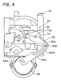
- FIG. 4 shows the throttle valve 70 in the wide-open position.
- a return spring 92 fastened to a tip portion of the throttle lever 80b located beyond the connection point of the rotating shaft 70s as viewed from the link pin 80b1 operates to energize the throttle valve 70 in the closing direction (in the direction of returning the link mechanism 80 from the state shown in FIG. 4 to that shown in FIG. 2).
- an abutment lug 80b2 provided on the throttle lever 80b collides with a stop 94 formed on the side face of the carburetor 38 to restrict further movement in the closing direction.
- the link mechanism 80 will now be explained in further detail with reference to FIG. 5.
- FIG. 5 is an explanatory diagram showing the operation and other aspects of the motor 46 and link mechanism 80.
- the solid-line representation shows the link mechanism 80 when the throttle valve (not shown) is at the fully closed position, and the broken-line representation shows the link mechanism 80 when the throttle valve is in the wide-open position.
- the link mechanism 80 is configured so that the output shaft 46s, the link pin 80b1, the throttle lever 80b and the rotating shaft 70s lie on a straight line when the throttle valve is fully closed. If, when the link mechanism 80 is in this condition, the output of the motor 46 is applied to the link lever 80a to rotate it clockwise as viewed in the drawing, the link pin 80b1 will move along the long hole 80a1 to rotate the throttle lever 80b and the throttle valve rotating shaft 70s counterclockwise and thus drive the throttle valve in the opening direction.
- the link mechanism 80 is configured so that the output shaft 46s, the link pin 80b1, the throttle lever 80b and the rotating shaft 70s lie on a straight line when the throttle valve is fully closed, it follows that the distance between the output shaft 46s and the link pin 80b1 of the throttle lever 80b is shortest when the throttle valve is fully closed. And from this it follows that the displacement (rotation angle) of the throttle valve 70 in response to the displacement (rotation) output of the motor 46 is smallest (finest) when the throttle valve 70 is fully or almost fully closed. It also follows that the reduction ratio is maximum at or near fully closed.
- the throttle valve 70 when the opening of the throttle valve 70 is small (i.e., when pressure difference between upstream and downstream of the throttle valve is large), the throttle valve 70 can be finely opened and closed. Further, when the opening of the throttle valve 70 is fully or almost fully closed, seizing of the throttle valve 70 can be prevented because the reduction ratio is maximum (throttle valve drive torque is maximum).
- the throttle valve 70 when the opening of the throttle valve 70 is large (i.e., when pressure difference between upstream and downstream of the throttle valve is small), the throttle valve 70 can be opened and closed at high speed and, therefore, the engine speed control response is enhanced owing to, for example, suppression of instantaneous changes in engine speed NE with change in load (instantaneous change (rise) in engine speed with transition from a "load-on” to a "load-off' condition).
- the link lever 80a and the throttle lever 80b interconnecting the motor output shaft 46s and the rotating shaft 70s are connected by inserting the link pin 80b1 in the long hole 80a1 to be movable therein.
- the degree of axial alignment required in this arrangement is substantially less severe than in the case of gear interconnection, the cost of fabrication can be reduced.
- the long hole 80a1 is formed to have the shape of an arc defined by a circle (designated A in the FIG. 5) projecting in the direction that the throttle opening is increased.
- the arcuately formed long hole 80a1 solid line
- the radius of curvature rA of the long hole 80a1 and the rotational radius of curvature rB of the link pin 80b1 are made the same in this embodiment. This enables the foregoing effects to be obtained still more markedly, as will be explained in following.
- FIG. 7 shows the change d ⁇ th in throttle opening when the radius of curvature rA of the long hole 80a1 is defined as about one half the rotational radius of curvature rB of the link pin 80b1.
- the radius of curvature rA of the long hole 80a1 too small makes the change d ⁇ th grow smaller beyond a certain throttle opening.
- setting the radius of curvature rA of the long hole 80a1 too large makes it approach tangential, which is disadvantageous in terms of space utilization, and also lowers the rate at which the change d ⁇ th increases.
- a throttle valve ordinarily has an opening range of about 90 degrees between fully closed and wide open (a somewhat smaller range if fully closed is defined as a position a few degrees in the open direction from the 90 degree position so as to prevent valve seizing).
- the inventors discovered that in the case of a throttle valve having such an opening range of about 90 degrees, the change d ⁇ th in the throttle opening can be optimally incremented from fully closed toward wide open by defining the radius of curvature rA of the long hole 80a1 and the rotational radius of curvature rB of the link pin 80b1 to be the same or substantially the same.
- FIG. 8 shows how throttle opening ⁇ th varies as a function of motor rotation angle ⁇ m when the link mechanism 80 of this embodiment is used.
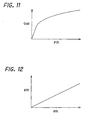
- the relationship between throttle opening ⁇ th and motor rotation angle ⁇ m illustrated in this drawing is considered in conjunction with the relationship between throttle opening ⁇ th and amount of intake air Gair shown in FIG. 11 (i.e., the relationship between the pressure differences upstream and downstream of the throttle valve), it can be seen that the proportional relationship shown FIG. 9 can be established between motor rotation angle ⁇ m and amount of intake air Gair.
- the dimensions of the different parts of the link mechanism 80 should be determined taking into account the output torque of the motor 46, in the same way that the reduction ratio of gearing would be determined.
- the distance between the output shaft 46s and the rotating shaft 70s of the throttle valve is set at 37 mm
- the length of the throttle lever 80b (distance from the throttle valve rotating shaft 70s to the link pin 80b1) at 18.5 mm
- the length of the link lever 80a (distance from the motor output shaft 46s to the point of contact with the link pin 80b1) at 18.5 mm when throttle valve is fully closed and 35.9 mm when it is wide open.
- the opening/closing speed at wide open is about 6.5 times that at fully closed.
- This embodiment is thus configured so that the amount of displacement (rotation angle) of the throttle valve 70 relative to the displacement (rotation) of the motor 46 is smallest (finest) at or near fully closed to enable fine opening/closing when the throttle opening is small and, further, so that the throttle valve 70 can be opened/closed at high speed when the throttle opening is large.
- the engine speed NE can therefore be accurately controlled with excellent response irrespective of throttle opening.
- Other advantages include prevention of throttle valve seizing and reduced fabrication cost.
- the long hole 80a1 is made arcuate and the radius of curvature rA of the long hole 80a1 is made the same as the rotational radius of curvature rB of the locus of the link pin 80b1, the foregoing effects are enhanced and the size of link mechanism 80 can be reduced for better space utilization.
- FIG. 13 is a schematic diagram showing another throttle system for a general-purpose engine according to a second embodiment of this invention, together with the general-purpose engine in which it is installed.
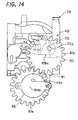
- FIG 14 is a front view and FIG. 15 a right side view of the throttle system 40.
- the throttle system 40 of this second embodiment will now be explained with reference to FIGs. 13 to 15, focusing particularly on the points of difference from the first embodiment.
- the throttle system 40 in the second embodiment is composed of the throttle valve 70 and an output transmission mechanism 81 which is similar to the mechanism 80 in the first embodiment, but is constituted as a gear mechanism.
- the output of the motor 46 is transmitted to the throttle valve 70 through the link mechanism 81 interconnecting the two.
- the gear mechanism 81 comprises a drive gear 81a (the first gear) and a driven gear 81b (the second gear) meshed therewith.
- the drive gear 81a is attached or connected to the output shaft 46s of the motor 46 at a location a prescribed distance apart from its gear center 81ac.
- the driven gear 81b is attached or connected to the rotating shaft 70s of the throttle valve 70 at a location a prescribed distance apart from its gear center 81bc.
- the drive gear 81a and driven gear 81b are each constituted as an eccentric gear whose axis of rotation and center do not coincide.
- FIG. 14 shows the throttle system 40 when the throttle valve 70 is in the fully closed position (which may in practice be defined as a position a few degrees in the open direction from the totally closed (90 degree) position so as to prevent valve seizing).
- FIG. 16 shows the throttle valve 70 in the wide-open position.
- a return spring 92 (shown in FIG. 15) fastened to the driven gear 81b operates to energize the throttle valve 70 in the closing direction (in the direction of returning the gear mechanism 81 from the state shown in FIG. 16 to that shown in FIG. 14).
- an abutment lug 96 joined to the rotating shaft 70s of the throttle valve collides with a stop 94 formed on the side face of the carburetor 38 to restrict further movement in the closing direction.
- the gear mechanism 81 will now be explained with reference to FIG. 17 and FIG. 18.
- FIG. 17 is an explanatory diagram showing the gear mechanism 81 when the throttle valve is at the wide-open position.
- FIG. 18 is an explanatory diagram showing it when the throttle valve is in the fully closed position.
- the drive gear 81a and driven gear 81b both have a base circle of radius d and are identically shaped.
- the motor output shaft 46s is fixed to the drive gear 81a at a location apart from its gear center 81ac by distance ⁇ in the direction toward the driven gear 81b.
- the drive gear 81a is decentered by distance ⁇ .
- the rotating shaft 70s of the throttle valve is fixed to the driven gear 81b at a location apart from its gear center 81bc by distance ⁇ in the direction away from the drive gear 81 a. Thus it is also decentered.
- the gear mechanism 81 is configured so that the gear center 81ac, the motor output shaft 46s, the gear center 81bc, and the rotating shaft 70s of the throttle valve lie on a straight line when the throttle valve is fully closed.
- db / da is maximum when the throttle valve is at or near fully closed. This means that the reduction ratio is maximum when the throttle valve is at or near fully closed.
- FIG. 19 shows how throttle opening ⁇ th varies as a function of motor rotation angle ⁇ m.
- the symbol ⁇ in the drawing represents eccentricity defined as 2 ⁇ / L, where L is the distance between the output shaft 46s and the rotating shaft 70S. If the shaft-to-shaft distance L is 37.0 mm, for instance, the eccentric offset ⁇ becomes 4.6 mm, 9.3 mm and 13.9 mm when the eccentricity ⁇ is 0.25, 0.50 and 0.75.
- a throttle valve ordinarily has an opening range of about 90 degrees (a somewhat smaller range if fully closed is defined as a position a few degrees in the open direction from the 90 degree position so as to prevent valve seizing).
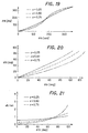
- FIG. 20 zooms in on the region of FIG. 19 where ⁇ th is 90 degrees or less.
- change (rate of increase) in throttle opening ⁇ th relative to change in motor rotation angle ⁇ m is minimum when the throttle valve is at or near fully closed.
- change (rate of increase) in throttle opening ⁇ th relative to change in motor rotation angle ⁇ m increases with increasing throttle opening ⁇ th.
- the rate of increase rises with increasing eccentricity ⁇ .
- the angular velocity of the drive gear 81a is defined as ⁇ a and that of the driven gear 81b as ⁇ b
- the angular velocity ratio ⁇ b / ⁇ a varies as a function of ⁇ th as shown in FIG. 21.
- the opening/closing speed increases with increasing throttle opening ⁇ th.
- the rate of increase rises with increasing eccentricity ⁇ .
- the throttle valve 70 can be finely opened and closed when the throttle opening ⁇ th is small (i.e., when pressure difference between upstream and downstream of the throttle valve is large). Further, when the opening of the throttle valve 70 is fully or almost fully closed, seizing of the throttle valve 70 can be prevented because the reduction ratio is maximum (throttle valve drive torque is maximum).
- the throttle valve 70 when the opening of the throttle valve 70 is large (i.e., when pressure difference between upstream and downstream of the throttle valve is small), the throttle valve 70 can be opened and closed at high speed and, therefore, the engine speed control response is enhanced owing to, for example, suppression of instantaneous changes in engine speed NE with change in load (instantaneous change (rise) in engine speed with transition from a "load-on” to a "load-off” condition).
- a throttle system for a general-purpose engine that is a third embodiment of this invention will now be explained with reference to FIGs. 22 to 24.
- the throttle system 400 of the third embodiment comprises an output transmission mechanism 800 also constituted as a gear mechanism which is composed of a drive gear 800a and a driven gear 800b, which are identically shaped elliptic gears having a major axis radius dl and a minor axis radius d2.
- the focus of the drive gear 800a farther from the driven gear 800b is defined as Fa1 and the focus thereof closer to the driven gear 800b is defined as Fa2.
- the motor output shaft 46s is situated at the closer focus Fa2.
- the focus of the driven gear 800b farther from the drive gear 800a is defined as Fb1 and the focus thereof closer to the drive gear 800a is defined as Fb2.
- the rotating shaft 70s is situated at the farther focus Fb1.
- FIG. 22 shows the gear mechanism 800 when the throttle valve is in the fully closed position.
- the gear mechanism 800 is configured so that the foci Fa1, Fa2, Fb1 and Fb2, the motor output shaft 46s, and the rotating shaft 70s of the throttle valve lie on a straight line when the throttle valve is fully closed.
- ⁇ a ⁇ a ⁇ b ⁇ b
- ⁇ a a line segment between an arbitrary point Aa on the ellipse of the drive gear 800a and the focus Fa2
- ⁇ b a line segment between a point Ab on the ellipse of the driven gear 800b that is symmetrical to the point Aa and the focus Fb2.
- FIG. 23 shows how throttle opening ⁇ th varies as a function of motor rotation angle ⁇ m in the third embodiment.
- change (rate of increase) in throttle opening ⁇ th relative to change in motor rotation angle ⁇ m is minimum when the throttle valve is at or near fully closed.
- change (rate of increase) in throttle opening ⁇ th relative to change in motor rotation angle ⁇ m increases with increasing throttle opening ⁇ th.
- the rate of increase rises with increasing eccentricity ⁇ .
- the angular velocity of the drive gear 800a is defined as ⁇ a and that of the driven gear 800b as ⁇ b
- the angular velocity ratio ⁇ b/ ⁇ a varies as a function of ⁇ th as shown in FIG 24.
- the opening/closing speed increases with increasing throttle opening ⁇ th.
- the rate of increase rises with increasing eccentricity ⁇ .
- the throttle valve 70 can be finely opened and closed when the opening of the throttle valve 70 is small. Further, when the opening of the throttle valve 70 is fully or almost fully closed, seizing of the throttle valve 70 can be prevented because the reduction ratio is maximum.
- the throttle valve 70 when the opening of the throttle valve 70 is large, the throttle valve 70 can be opened and closed at high speed and, therefore, engine speed NE can be accurately controlled with good response regardless of throttle opening.
- a larger eccentricity ⁇ enables the reduction ratio of the internal gearing of the motor 46 to be set to a larger value to further enhance the foregoing effects.
- the throttle systems of the second and third embodiments are configured so that the output of the motor 46 is transmitted to the throttle valve 70 through the gear mechanism 81, 800, the gear mechanism 81, 800 is composed of eccentric gears or elliptical gears, and the rotation angle of the driven gear 81b, 800b (throttle opening ⁇ th) relative to the rotation angle of the drive gear 81a, 800a (motor rotation angle ⁇ m) becomes minimum when the throttle valve 70 is at or near fully closed and increases with increasing throttle opening.
- the opening of the throttle valve 70 can be can finely opened and closed when the opening is small and be opened and closed at high speed when the opening is large, thereby enabling the engine speed NE to be accurately controlled with good response regardless of throttle opening.
- seizing of the throttle valve can be prevented.
- the first to third embodiments are configured to have a throttle system for a general-purpose engine (10), having an actuator (stepper motor 46) connected to a throttle valve (70) of the engine, the actuator being displaceable to open or close the throttle valve so as to regulate amount of intake air, characterized in that: an output transmission mechanism (80, 81, 800) is provided between the actuator (46) and the throttle valve (70) to transmit an output of the actuator to the throttle value such that an output of the mechanism relative to the output of the actuator when the throttle valve is closed, i.e., is fully closed or almost fully closed is smaller than that when the throttle value is not fully closed or not almost fully closed.
- an output transmission mechanism 80, 81, 800
- this invention can provide a throttle system for a general-purpose engine in which an output transmission mechanism for transmitting the displacement output of an actuator to a throttle valve is structured so that its displacement in response to the displacement output of the actuator is minimum when the throttle valve is fully or almost fully closed.
- the throttle opening can be finely regulated (opened/closed) when the throttle opening is small and can be opened/closed at high speed when the throttle opening is large.
- seizing of the throttle valve can be prevented.
- the output transmission mechanism (80) is constituted as a link mechanism (80) having; a link lever (80a) connected to an output shaft (46s) of the actuator (46); and a throttle lever (80b) whose one end is connected to the link lever to be displaceable relative to the link lever and whose other end is connected to a rotating shaft (70s) of the throttle valve (70); wherein the link lever (80a) and the throttle lever (80b) are connected to transmit the output of the actuator to the throttle valvesuch that displacement of the mechanism relative to the output of the actuator is minimum when the throttle valve is closed, i.e., is fully closed or almost fully closed.
- the throttle lever (80b) can be formed with a link pin (80b1) that is movable in a hole (80a1) formed at the link lever, and the hole (80a1) is an arcuate hole having a same radius of curvature as a rotational radius of curvature of a locus of the link pin (80b1).
- this invention can provide a throttle system for a general-purpose engine that even more markedly achieves the foregoing effects, that by enabling the link lever and the throttle lever to be made small enhances space utilization efficiency, and that by eliminating the need for strict axial alignment between the motor output shaft and the throttle valve enables fabrication at lower cost than when utilizing gear interconnection.
- the output transmission mechanism is constituted as a gear mechanism (81, 800) having; a first gear (81a, 800a) connected to an output shaft (46s) of the actuator (46); and a second gear (81b, 800b) connected to a rotating shaft (70s) of the throttle valve (70); wherein the first gear (81a, 800a) and the second gear (81b, 800b) are meshed together such that a rotation angle of the second gear relative to a rotation angle of the first gear is minimum when the throttle valve (70) is fully closed or almost fully closed.
- this invention can also provide a throttle system for a general-purpose engine in which the displacement output of an actuator is transmitted to a throttle valve through a first gear and a second gear and the rotation angle of the second gear relative to the rotation angle of the first gear is minimum, i.e., the reduction ratio is maximum, when the throttle valve is at or near fully closed.
- the throttle valve can be finely regulated (opened/closed) when the throttle opening is small and can be opened/closed at high speed when the throttle opening is large.
- seizing of the throttle valve can be prevented.
- the output shaft (46s) of the actuator (46) can be connected to the first gear (81a, 800a) at a location apart from a center (81ac) of the first gear (81a, 800a), and the rotating shaft (70s) of the throttle valve (70) is connected to the second gear (81b, 800b) at a location apart from a center (81bc) of the second gear (81b, 800b).
- the first and second gears are eccentric gears, or the first and second gears are elliptic gears.
Landscapes
- Engineering & Computer Science (AREA)
- Chemical & Material Sciences (AREA)
- Combustion & Propulsion (AREA)
- Mechanical Engineering (AREA)
- General Engineering & Computer Science (AREA)
- Control Of Throttle Valves Provided In The Intake System Or In The Exhaust System (AREA)
Abstract
Description
Claims (8)
- A throttle system for a general-purpose engine (10), having an actuator (46) connected to a throttle valve (70) of the engine, the actuator being displaceable to open or close the throttle valve so as to regulate amount of intake air,
characterized in that:an output transmission mechanism (80, 81, 800) is provided between the actuator (46) and the throttle valve (70) to transmit an output of the actuator to the throttle valve such that an output of the mechanism relative to the output of the actuator when the throttle valve is closed is smaller than that when the throttle valve is not closed. - A throttle system according to claim 1, wherein the output transmission mechanism is constituted as a link mechanism (80) having;
a link lever (80a) connected to an output shaft (46s) of the actuator (46); and
a throttle lever (80b) whose one end is connected to the link lever to be displaceable relative to the link lever and whose other end is connected to a rotating shaft (70s) of the throttle valve (70);
wherein the link lever (80a) and the throttle lever (80b) are connected to transmit the output of the actuator to the throttle valve such that displacement of the mechanism relative to the output of the actuator is minimum when the throttle valve is closed. - A throttle system according to claim 2, wherein the throttle lever (80b) is formed with a link pin (80b1) that is movable in a hole (80a1) formed at the link lever.
- A throttle system according to claim 3, wherein the hole (80a1) is an arcuate hole having a same radius of curvature as a rotational radius of curvature of a locus of the link pin (80b1).
- A throttle system according to claim 1, wherein the output transmission mechanism is constituted as a gear mechanism (81, 800) having;
a first gear (81a, 800a) connected to an output shaft (46s) of the actuator (46);
and
a second gear (81b, 800b) connected to a rotating shaft (70s) of the throttle valve (70);
wherein the first gear (81a, 800a) and the second gear (81b, 800b) are meshed together such that a rotation angle of the second gear relative to a rotation angle of the first gear is minimum when the throttle valve (70) is closed. - A throttle system according to claim 5, wherein the output shaft (46a) of the actuator (46) is connected to the first gear (81a, 800a) at a location apart from a center (81ac) of the first gear (81a, 800a), and the rotating shaft (70s) of the throttle valve (70) is connected to the second gear (81b, 800b) at a location apart from a center (81bc) of the second gear (81b, 800b).
- A throttle system according to claim 6, wherein the first and second gears are eccentric gears.
- A throttle system according to claim 6 or 7, wherein the first and second gears are elliptic gears.
Applications Claiming Priority (4)
| Application Number | Priority Date | Filing Date | Title |
|---|---|---|---|
| JP2002117375 | 2002-04-19 | ||
| JP2002117376 | 2002-04-19 | ||
| JP2002117376A JP3869299B2 (en) | 2002-04-19 | 2002-04-19 | General-purpose engine throttle device |
| JP2002117375A JP3869298B2 (en) | 2002-04-19 | 2002-04-19 | General-purpose engine throttle device |
Publications (3)
| Publication Number | Publication Date |
|---|---|
| EP1359301A2 true EP1359301A2 (en) | 2003-11-05 |
| EP1359301A3 EP1359301A3 (en) | 2004-01-28 |
| EP1359301B1 EP1359301B1 (en) | 2006-03-15 |
Family
ID=29217982
Family Applications (1)
| Application Number | Title | Priority Date | Filing Date |
|---|---|---|---|
| EP03252480A Expired - Lifetime EP1359301B1 (en) | 2002-04-19 | 2003-04-17 | Throttle system for general-purpose engine |
Country Status (4)
| Country | Link |
|---|---|
| US (1) | US6761145B2 (en) |
| EP (1) | EP1359301B1 (en) |
| CN (1) | CN1296612C (en) |
| DE (1) | DE60304003T2 (en) |
Cited By (1)
| Publication number | Priority date | Publication date | Assignee | Title |
|---|---|---|---|---|
| DE102005051304A1 (en) * | 2005-10-26 | 2007-05-03 | Siemens Ag | Impurities cleaning method for gas feedback valve, involves providing valve flap that is connected with tooth segment, where toothed circles of segments comprise changeable radii with which shaft is provided with increasing torques |
Families Citing this family (21)
| Publication number | Priority date | Publication date | Assignee | Title |
|---|---|---|---|---|
| DE10238364A1 (en) * | 2002-08-22 | 2004-03-04 | Andreas Stihl Ag & Co | actuator |
| US6855091B1 (en) * | 2003-05-09 | 2005-02-15 | Stephen G. Holmes | System for controlling an automatic transmission throttle valve and method of use |
| JP4286636B2 (en) * | 2003-11-12 | 2009-07-01 | ハスクバーナ・ゼノア株式会社 | Conductive coupling mechanism between angled valve stems |
| JP4398775B2 (en) * | 2004-04-23 | 2010-01-13 | 株式会社ケーヒン | Idling opening degree control device in intake control device |
| JP4292123B2 (en) * | 2004-08-18 | 2009-07-08 | 本田技研工業株式会社 | Electronic controller for carburetor valve of general-purpose engine |
| ES2307095T3 (en) * | 2004-08-18 | 2008-11-16 | Honda Motor Co., Ltd. | CARBURETOR ELECTRONIC CONTROL SYSTEM. |
| US20070034431A1 (en) * | 2005-08-09 | 2007-02-15 | Jackson Vincent E | Governor guard |
| US8042514B2 (en) * | 2008-07-24 | 2011-10-25 | Honda Motor Company, Ltd. | Throttle bodies and saddle-type vehicles including valved intake conduits for engine |
| US8616180B2 (en) * | 2009-07-09 | 2013-12-31 | Honda Motor Co., Ltd. | Automatic idle systems and methods |
| US8567371B2 (en) * | 2010-03-02 | 2013-10-29 | Honda Motor Co., Ltd. | Throttle auto idle with blade brake clutch |
| CA2801334C (en) | 2010-06-03 | 2020-03-10 | Polaris Industries Inc. | Electronic throttle control |
| US9205717B2 (en) | 2012-11-07 | 2015-12-08 | Polaris Industries Inc. | Vehicle having suspension with continuous damping control |
| US9261030B2 (en) | 2013-05-20 | 2016-02-16 | Kohler Co. | Automatic fuel shutoff |
| US9074535B1 (en) | 2013-12-19 | 2015-07-07 | Kohler Co. | Integrated engine control apparatus and method of operating same |
| CN107406094B (en) | 2014-10-31 | 2020-04-14 | 北极星工业有限公司 | System and method for controlling a vehicle |
| US9463686B2 (en) * | 2014-12-30 | 2016-10-11 | Kawasaki Jukogyo Kabushiki Kaisha | Utility vehicle |
| CA3043481C (en) | 2016-11-18 | 2022-07-26 | Polaris Industries Inc. | Vehicle having adjustable suspension |
| US10406884B2 (en) | 2017-06-09 | 2019-09-10 | Polaris Industries Inc. | Adjustable vehicle suspension system |
| US10987987B2 (en) | 2018-11-21 | 2021-04-27 | Polaris Industries Inc. | Vehicle having adjustable compression and rebound damping |
| US12397878B2 (en) | 2020-05-20 | 2025-08-26 | Polaris Industries Inc. | Systems and methods of adjustable suspensions for off-road recreational vehicles |
| MX2022015902A (en) | 2020-07-17 | 2023-01-24 | Polaris Inc | Adjustable suspensions and vehicle operation for off-road recreational vehicles. |
Family Cites Families (16)
| Publication number | Priority date | Publication date | Assignee | Title |
|---|---|---|---|---|
| USRE34138E (en) * | 1983-08-19 | 1992-12-08 | Outboard Marine Corporation | Throttle and timing linkage |
| DE3609849C1 (en) * | 1986-03-22 | 1987-07-30 | Daimler Benz Ag | Device for regulating an internal combustion engine in a motor vehicle |
| DE3843056A1 (en) * | 1987-12-23 | 1989-07-06 | Mazda Motor | ENGINE POWER CONTROL ARRANGEMENT |
| JPH02204641A (en) * | 1989-01-31 | 1990-08-14 | Aisin Seiki Co Ltd | Throttle controller |
| JPH04224241A (en) * | 1990-12-26 | 1992-08-13 | Aisin Seiki Co Ltd | Throttle control device |
| US5165298A (en) * | 1991-10-08 | 1992-11-24 | General Motors Corporation | Throttle cable linkage |
| JPH05187287A (en) * | 1992-01-09 | 1993-07-27 | Fujitsu Ten Ltd | Link-less throttle control device |
| CN2223782Y (en) * | 1995-06-23 | 1996-04-03 | 吉林工业大学 | Vehicle power source control device |
| US5562081A (en) * | 1995-09-12 | 1996-10-08 | Philips Electronics North America Corporation | Electrically-controlled throttle with variable-ratio drive |
| JPH1047520A (en) | 1996-07-31 | 1998-02-20 | Toyota Autom Loom Works Ltd | Throttle body |
| JP3331135B2 (en) * | 1997-01-09 | 2002-10-07 | 株式会社ユニシアジェックス | Intake throttle valve device for internal combustion engine |
| US6463826B1 (en) * | 1997-11-03 | 2002-10-15 | Randy Bouchillon | Automobile transmission cable device |
| US6481415B1 (en) * | 1999-03-25 | 2002-11-19 | Siemens Canada Limited | Electronic throttle control |
| CA2316059A1 (en) * | 1999-08-24 | 2001-02-24 | Virgilio C. Go Boncan | Methods and compositions for use in cementing in cold environments |
| JP2001263098A (en) | 2000-03-22 | 2001-09-26 | Denso Corp | Throttle device |
| CN2485433Y (en) * | 2001-07-13 | 2002-04-10 | 哈尔滨志阳汽车电气股份有限公司 | Throttle valve body |
-
2003
- 2003-04-17 EP EP03252480A patent/EP1359301B1/en not_active Expired - Lifetime
- 2003-04-17 DE DE60304003T patent/DE60304003T2/en not_active Expired - Lifetime
- 2003-04-18 CN CNB031106285A patent/CN1296612C/en not_active Expired - Fee Related
- 2003-04-18 US US10/418,129 patent/US6761145B2/en not_active Expired - Fee Related
Cited By (1)
| Publication number | Priority date | Publication date | Assignee | Title |
|---|---|---|---|---|
| DE102005051304A1 (en) * | 2005-10-26 | 2007-05-03 | Siemens Ag | Impurities cleaning method for gas feedback valve, involves providing valve flap that is connected with tooth segment, where toothed circles of segments comprise changeable radii with which shaft is provided with increasing torques |
Also Published As
| Publication number | Publication date |
|---|---|
| CN1296612C (en) | 2007-01-24 |
| EP1359301B1 (en) | 2006-03-15 |
| US6761145B2 (en) | 2004-07-13 |
| CN1451856A (en) | 2003-10-29 |
| DE60304003T2 (en) | 2006-08-17 |
| DE60304003D1 (en) | 2006-05-11 |
| US20030196638A1 (en) | 2003-10-23 |
| EP1359301A3 (en) | 2004-01-28 |
Similar Documents
| Publication | Publication Date | Title |
|---|---|---|
| US6761145B2 (en) | Throttle system for general-purpose engine | |
| US6267099B1 (en) | Throttle valve control device for an internal combustion engine | |
| US5027769A (en) | Throttle valve control apparatus | |
| US7243635B2 (en) | Throttle valve opening and closing device | |
| KR0152087B1 (en) | Throttle Actuator and Control System | |
| US4527534A (en) | Fuel intake control system for supercharged engine | |
| US7096851B2 (en) | Throttle device for multipurpose engine | |
| US20060112930A1 (en) | Throttle device for multipurpose engine | |
| JPH0396631A (en) | Control device for reducing hydrocarbons in exhaust gases | |
| JPH02227527A (en) | Intake air amount control method for internal combustion engine | |
| US7146947B2 (en) | Arrangement for adjusting the angle of rotation of a camshaft relative to a crankshaft | |
| US6964259B1 (en) | Nonadjustable outboard motor throttle linkage | |
| JP3869298B2 (en) | General-purpose engine throttle device | |
| JP3869299B2 (en) | General-purpose engine throttle device | |
| US5163400A (en) | Engine unit | |
| US5345920A (en) | Supercharging pressure control system for supercharged internal combustion engines | |
| US5678519A (en) | Engine control system | |
| EP0290980B1 (en) | Apparatus for controlling intake air flow rate in internal combustion engine | |
| EP0619421A2 (en) | Control system for a two-stroke engine | |
| JPH07253033A (en) | Engine speed regulating method and governor device | |
| JP2000297660A (en) | Intake flow control device for diesel engine | |
| JP2005016437A (en) | General-purpose engine throttle device | |
| US4130609A (en) | Staged accelerator pump | |
| JP3114747B2 (en) | Engine governor | |
| US20010027758A1 (en) | Exhaust valve device for two-cycle engine |
Legal Events
| Date | Code | Title | Description |
|---|---|---|---|
| PUAI | Public reference made under article 153(3) epc to a published international application that has entered the european phase |
Free format text: ORIGINAL CODE: 0009012 |
|
| AK | Designated contracting states |
Kind code of ref document: A2 Designated state(s): AT BE BG CH CY CZ DE DK EE ES FI FR GB GR HU IE IT LI LU MC NL PT RO SE SI SK TR |
|
| AX | Request for extension of the european patent |
Extension state: AL LT LV MK |
|
| PUAL | Search report despatched |
Free format text: ORIGINAL CODE: 0009013 |
|
| AK | Designated contracting states |
Kind code of ref document: A3 Designated state(s): AT BE BG CH CY CZ DE DK EE ES FI FR GB GR HU IE IT LI LU MC NL PT RO SE SI SK TR |
|
| AX | Request for extension of the european patent |
Extension state: AL LT LV MK |
|
| AKX | Designation fees paid | ||
| 17P | Request for examination filed |
Effective date: 20040728 |
|
| RBV | Designated contracting states (corrected) |
Designated state(s): DE FR GB |
|
| REG | Reference to a national code |
Ref country code: DE Ref legal event code: 8566 |
|
| 17Q | First examination report despatched |
Effective date: 20041022 |
|
| GRAP | Despatch of communication of intention to grant a patent |
Free format text: ORIGINAL CODE: EPIDOSNIGR1 |
|
| GRAS | Grant fee paid |
Free format text: ORIGINAL CODE: EPIDOSNIGR3 |
|
| GRAA | (expected) grant |
Free format text: ORIGINAL CODE: 0009210 |
|
| AK | Designated contracting states |
Kind code of ref document: B1 Designated state(s): DE FR GB |
|
| REG | Reference to a national code |
Ref country code: GB Ref legal event code: FG4D |
|
| REF | Corresponds to: |
Ref document number: 60304003 Country of ref document: DE Date of ref document: 20060511 Kind code of ref document: P |
|
| ET | Fr: translation filed | ||
| PLBE | No opposition filed within time limit |
Free format text: ORIGINAL CODE: 0009261 |
|
| STAA | Information on the status of an ep patent application or granted ep patent |
Free format text: STATUS: NO OPPOSITION FILED WITHIN TIME LIMIT |
|
| 26N | No opposition filed |
Effective date: 20061218 |
|
| REG | Reference to a national code |
Ref country code: FR Ref legal event code: PLFP Year of fee payment: 13 |
|
| PGFP | Annual fee paid to national office [announced via postgrant information from national office to epo] |
Ref country code: GB Payment date: 20150415 Year of fee payment: 13 Ref country code: DE Payment date: 20150414 Year of fee payment: 13 |
|
| PGFP | Annual fee paid to national office [announced via postgrant information from national office to epo] |
Ref country code: FR Payment date: 20150408 Year of fee payment: 13 |
|
| REG | Reference to a national code |
Ref country code: DE Ref legal event code: R119 Ref document number: 60304003 Country of ref document: DE |
|
| GBPC | Gb: european patent ceased through non-payment of renewal fee |
Effective date: 20160417 |
|
| REG | Reference to a national code |
Ref country code: FR Ref legal event code: ST Effective date: 20161230 |
|
| PG25 | Lapsed in a contracting state [announced via postgrant information from national office to epo] |
Ref country code: GB Free format text: LAPSE BECAUSE OF NON-PAYMENT OF DUE FEES Effective date: 20160417 Ref country code: DE Free format text: LAPSE BECAUSE OF NON-PAYMENT OF DUE FEES Effective date: 20161101 Ref country code: FR Free format text: LAPSE BECAUSE OF NON-PAYMENT OF DUE FEES Effective date: 20160502 |