EP1359040A2 - Vehicular power plant mounting system - Google Patents
Vehicular power plant mounting system Download PDFInfo
- Publication number
- EP1359040A2 EP1359040A2 EP03252536A EP03252536A EP1359040A2 EP 1359040 A2 EP1359040 A2 EP 1359040A2 EP 03252536 A EP03252536 A EP 03252536A EP 03252536 A EP03252536 A EP 03252536A EP 1359040 A2 EP1359040 A2 EP 1359040A2
- Authority
- EP
- European Patent Office
- Prior art keywords
- power plant
- engine
- inertia
- characteristic value
- vehicle body
- Prior art date
- Legal status (The legal status is an assumption and is not a legal conclusion. Google has not performed a legal analysis and makes no representation as to the accuracy of the status listed.)
- Granted
Links
Images



Classifications
-
- B—PERFORMING OPERATIONS; TRANSPORTING
- B60—VEHICLES IN GENERAL
- B60K—ARRANGEMENT OR MOUNTING OF PROPULSION UNITS OR OF TRANSMISSIONS IN VEHICLES; ARRANGEMENT OR MOUNTING OF PLURAL DIVERSE PRIME-MOVERS IN VEHICLES; AUXILIARY DRIVES FOR VEHICLES; INSTRUMENTATION OR DASHBOARDS FOR VEHICLES; ARRANGEMENTS IN CONNECTION WITH COOLING, AIR INTAKE, GAS EXHAUST OR FUEL SUPPLY OF PROPULSION UNITS IN VEHICLES
- B60K5/00—Arrangement or mounting of internal-combustion or jet-propulsion units
- B60K5/12—Arrangement of engine supports
- B60K5/1208—Resilient supports
- B60K5/1216—Resilient supports characterised by the location of the supports relative to the motor or to each other
-
- F—MECHANICAL ENGINEERING; LIGHTING; HEATING; WEAPONS; BLASTING
- F16—ENGINEERING ELEMENTS AND UNITS; GENERAL MEASURES FOR PRODUCING AND MAINTAINING EFFECTIVE FUNCTIONING OF MACHINES OR INSTALLATIONS; THERMAL INSULATION IN GENERAL
- F16F—SPRINGS; SHOCK-ABSORBERS; MEANS FOR DAMPING VIBRATION
- F16F13/00—Units comprising springs of the non-fluid type as well as vibration-dampers, shock-absorbers, or fluid springs
- F16F13/04—Units comprising springs of the non-fluid type as well as vibration-dampers, shock-absorbers, or fluid springs comprising both a plastics spring and a damper, e.g. a friction damper
- F16F13/06—Units comprising springs of the non-fluid type as well as vibration-dampers, shock-absorbers, or fluid springs comprising both a plastics spring and a damper, e.g. a friction damper the damper being a fluid damper, e.g. the plastics spring not forming a part of the wall of the fluid chamber of the damper
- F16F13/08—Units comprising springs of the non-fluid type as well as vibration-dampers, shock-absorbers, or fluid springs comprising both a plastics spring and a damper, e.g. a friction damper the damper being a fluid damper, e.g. the plastics spring not forming a part of the wall of the fluid chamber of the damper the plastics spring forming at least a part of the wall of the fluid chamber of the damper
Definitions
- the present invention relates to an improved mounting system for mounting, on a vehicle body frame, a power plant that includes an engine and a transmission connected to the engine at one end along the axis of a crankshaft of the engine.
- front-wheel drive vehicles etc. generally employ a principal axis of inertia 4-point support type mounting system, in which a power plant, which is formed from an engine and a transmission connected to the engine, is mounted on a vehicle body frame at two points on opposite sides along the principal axis of inertia of the power plant and at two points on opposite sides along a direction substantially perpendicular to the principal axis of inertia.
- the vertical characteristic value is generally set at 7 to 10 Hz
- the roll characteristic value is set at 10 to 15 Hz.
- a torque rod type mounting system is known from, for example, Japanese Patent No. 2562485, having a support rigidity lower than that of the conventional principal axis of inertia 4-point support type mounting system.
- Use of such a torque rod type mounting system can increase the degrees of freedom in tuning, since the spring characteristics of the torque rod do not affect in the vertical direction and the spring characteristics in the vertical direction and the roll direction are not coupled.
- Japanese Patent No. 2562485 above does not disclose a method for improving the ride comfort over the entire ride frequency region.
- the present invention has been devised in view of the above-mentioned circumstances, and it is an object of at least the preferred embodiments of the present invention to provide a vehicular power plant mounting system that can improve the ride comfort over the entire ride frequency region.
- a vehicular power plant mounting system in which a power plant that includes an engine and a transmission connected to the engine at one end along an axis of a crankshaft of the engine is supported on a vehicle body frame via an engine side main mount and a transmission side main mount, each mount including a first elastic material and being disposed substantially on a principal axis of inertia of the power plant in such a manner that a vertical damping coefficient peak frequency can be set, and via a pair of upper and lower torque rods including a second elastic material which are disposed substantially horizontally within a plane substantially perpendicular to the axis of the crankshaft between the power plant and the vehicle body frame above and below drive shafts extending from the transmission, wherein a vertical characteristic value of a mounting structure that includes the two main mounts and the two torque rods is set at 5 to 7 Hz, a roll characteristic value around the principal axis of inertia of the mounting structure is set at 7 to 10 Hz,
- the vertical characteristic value of the mounting structure is set at 5 to 7 Hz
- a vertical characteristic value dynamic damper effect can be obtained.
- the roll characteristic value around the principal axis of inertia of the mounting structure is set at 7 to 10 Hz
- a dynamic damper effect can be obtained due to coupling of the vertical and roll modes
- the damping peak frequency of the two main mounts is set at 9 to 15 Hz
- a vehicle body frame responsive damping effect can be obtained due to the damping setting of the main mounts.
- the ride comfort can be improved at all ride frequencies from 5 to 15 Hz.
- a vehicular power plant mounting system in which a power plant that includes an engine and a transmission connected to the engine at one end along an axis of a crankshaft of the engine is supported on a vehicle body frame via an engine side main mount and a transmission side main mount, each mount including a first elastic material and being disposed substantially on a principal axis of inertia of the power plant in such a manner that a vertical damping coefficient peak frequency can be set, and via a pair of upper and lower torque rods including a second elastic material which are disposed substantially horizontally within a plane substantially perpendicular to the axis of the crankshaft between the power plant and the vehicle body frame above and below drive shafts extending from the transmission, wherein a frequency band of 5 to 15 Hz is divided into three bands, that is, upper, middle, and lower bands, and a vertical characteristic value of a mounting structure that includes the two main mounts and the two torque rods is set in the lower band, a roll characteristic value
- the frequency band of 5 to 15 Hz is divided into three bands, that is, upper, middle, and lower bands; since the vertical characteristic value of the mounting structure is set in the lower band, a vertical characteristic value dynamic damper effect can be obtained; since the roll characteristic value around the principal axis of inertia of the mounting structure is set in the middle band, a dynamic damper effect can be obtained due to coupling of the vertical and roll modes; and since the damping peak frequency of the two main mounts is set in the upper band, a vehicle body frame responsive damping effect can be obtained due to the damping setting of the main mounts. As a result, the ride comfort can be improved at all ride frequencies from 5 to 15 Hz.
- a power plant P is mounted in a front-engine, front-drive (FF) vehicle V, and is formed from a transversely mounted engine E having a crankshaft 5 running along the width direction of the vehicle V and a transmission T connected to the engine E at one end along the axis of the crankshaft 5.
- FF front-drive
- the power plant P is supported on a vehicle body frame F via an engine side main mount 6 and a transmission side main mount 7, which are disposed substantially on the principal axis of inertia. That is, a bracket 10 is attached to a cylinder block 8 and a cylinder head 9 of the engine E at the other end along the axis of the crankshaft 5, and the engine side main mount 6 is disposed between the bracket 10 and a right-hand front side frame 11 of the vehicle body frame F.
- a bracket 13 is attached to a left-hand front side frame 12 of the vehicle body frame F, and the transmission side main mount 7 is disposed between the bracket 13 and a transmission case 14 of the transmission T.
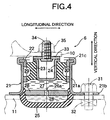
- the engine side main mount 6 includes a casing 21 having a cylindrical casing main portion 21a and a flange portion 21b projecting radially outward from the lower end of the casing main portion 21a.
- a substantially cylindrical outer tube 22 fitted inside the casing main portion 21a is fastened to the casing 21 by means of a crimped portion 21c formed at the upper end of the casing main portion 21a.
- An elastic material 23 is fixed to the inner periphery of the outer tube 22 by baking, and a cup-shaped inner tubular member 24 is fixed to the inner periphery of the elastic material 23 by baking.
- a cup-shaped elastic material 25 is fixed to the lower end of the casing main portion 21a by baking, and a partition 26 is fixed to the upper edge of the elastic material 25 by baking.
- a first liquid chamber 27 is formed between the partition 26 and the elastic material 23.
- a second liquid chamber 28 is formed between the partition 26 and the elastic material 25. The first and second liquid chambers 27, 28 communicate with each other via an orifice 26a provided in the partition 26.
- third and fourth liquid chambers 29, 30 are formed between the elastic material 23 and a middle section of the casing main portion 21a at positions in the longitudinal direction of the vehicle body.
- the third and fourth liquid chambers 29, 30 communicate with each other via an orifice (not illustrated).
- the flange portion 21b of the casing 21 is secured to the front side frame 11 of the vehicle body frame F by means of a plurality of bolts 31 and nuts 32.
- a support plate 33 secured to the inner tubular member 24 is secured by means of bolts 34 and nuts 35 to the bracket 10 attached to the engine E.
- the liquid moves through the orifice 26a so as to alternately increase and decrease the volumes of the first and second liquid chambers 27, 28, thereby generating a damping force to suppress vertical vibration of the power plant P. Furthermore, the liquid moves through the orifice (not illustrated) so as to alternately increase and decrease the volumes of the third and fourth liquid chambers 29, 30, thereby generating a damping force to suppress fore-and-aft vibration of the power plant P.
- Adjusting the dimensions of the orifice 26a enables the peak frequency of the vertical damping coefficient to be set.
- the transmission side main mount 7 has the same arrangement as that of the engine side main mount 6 so that the peak frequency of the vertical damping coefficient can be set, and detailed explanation thereof is omitted.
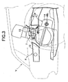
- the vehicle body frame F includes a bracket 37 disposed above the right-hand front side frame 11.
- a torque rod 38 disposed substantially horizontally within a plane substantially perpendicular to the axis of the crankshaft 5.
- This torque rod 38 includes elastic materials 39, 40 at opposite ends thereof.
- the front end of the torque rod 38 is connected to the bracket 10 via the elastic material 39 so that it can pivot around an axis parallel to the crankshaft 5.
- the rear end of the torque rod 38 is connected to the bracket 37 via the elastic material 40 so that it can pivot around an axis parallel to the crankshaft 5.
- the vehicle body frame F includes a cross member 41 providing a connection between the two front side frames 11, 12 to the rear of the power plant P.
- a torque rod 45 disposed substantially horizontally within a plane substantially perpendicular to the axis of the crankshaft 5.
- This torque rod 45 includes elastic materials 46, 47 at opposite ends thereof.
- the front end of the torque rod 45 is connected to the bracket 43 via the elastic material 46 so that it can pivot around an axis parallel to the crankshaft 5.
- the rear end of the torque rod 45 is connected to the bracket 42 via the elastic material 47 so that it can pivot around an axis parallel to the crankshaft 5.
- the torque rod 38 is disposed above drive shafts 48L, 48R extending laterally from the transmission T of the power plant P, whereas the other torque rod 45 is disposed below the drive shafts 48L, 48R.
- a frequency band of 5 to 15 Hz which corresponds to the ride frequencies, is divided into a lower band, for example, 5 to 7 Hz, a middle band, for example, 7 to 10 Hz, and an upper band, for example, 9 to 15 Hz.
- the vertical characteristic value of a mounting structure that includes the engine side and transmission side main mounts 6, 7 and the pair of torque rods 38, 45 is set in the lower band (5 to 7 Hz).
- the roll characteristic value around the principal axis of inertia of the mounting structure is set in the middle band (7 to 10 Hz).
- the damping peak frequency of the two main mounts 6, 7 is set in the upper band (9 to 15 Hz).
- the vertical characteristic value is about 10 Hz, and in the mounting system of the present invention, the vertical characteristic value is set lower than that of the conventional device.
- the roll characteristic value is about 16 Hz, and in the mounting system of the present invention, the roll characteristic value is set lower than that of the conventional device.
- the damping peak frequency of the two main mounts is about 6 to 8 Hz, and in the mounting system of the present invention, the damping peak frequency of the two main mounts 6, 7 is set higher than that of the conventional device.
- the frequency band of 5 to 15 Hz is divided into the three bands, that is, the lower, middle, and upper bands.
- the vertical characteristic value of the mounting structure which includes the two main mounts 6, 7 and the two torque rods 38, 45, is set in the lower band, the roll characteristic value around the principal axis of inertia of the mounting structure is set in the middle band, and the damping peak frequency of the two main mounts 6, 7 is set in the upper band.
- a vertical characteristic value dynamic damper effect can be obtained in the lower band
- a dynamic damper effect can be obtained due to coupling of the vertical and roll modes in the middle band
- a vehicle body frame responsive damping effect can be obtained in the upper band due to the damping setting of the main mounts 6, 7.
- a vibration isolation of, for example, "-10 dB" over the entire ride frequency region of 5 to 15 Hz, that is, the ride comfort can be improved over the entire ride frequency region of 5 to 15 Hz.
Landscapes
- Engineering & Computer Science (AREA)
- General Engineering & Computer Science (AREA)
- Mechanical Engineering (AREA)
- Chemical & Material Sciences (AREA)
- Combustion & Propulsion (AREA)
- Transportation (AREA)
- Arrangement Or Mounting Of Propulsion Units For Vehicles (AREA)
- Vibration Prevention Devices (AREA)
Abstract
Description
Claims (3)
- A vehicular power plant mounting system in which a power plant (P) comprising an engine (E) and a transmission (T) connected to the engine (E) at one end along an axis of a crankshaft (5) of the engine (E) is supported on a vehicle body frame (F) viawherein a vertical characteristic value of a mounting structure that includes the two main mounts (6, 7) and the two torque rods (38, 45) is set at 5 to 7 Hz,an engine side main mount (6) and a transmission side main mount (7), each mount (6,7) including a first elastic material (23, 25) and being disposed substantially on a principal axis of inertia of the power plant (P) in such a manner that a vertical damping coefficient peak frequency can be set, and viaa pair of upper and lower torque rods (38, 45) including a second elastic material (39, 40; 46, 47) which are disposed substantially horizontally within a plane substantially perpendicular to the axis of the crankshaft (5) between the power plant (P) and the vehicle body frame (F) above and below drive shafts (48L, 48R) extending from the transmission (T),
a roll characteristic value around the principal axis of inertia of the mounting structure is set at 7 to 10 Hz, and
a damping peak frequency of the two main mounts (6, 7) is set at 9 to 15 Hz. - A vehicular power plant mounting system in which a power plant (P) comprising an engine (E) and a transmission (T) connected to the engine (E) at one end along an axis of a crankshaft (5) of the engine (E) is supported on a vehicle body frame (F) viawherein a frequency band of 5 to 15 Hz is divided into three bands, that is, upper, middle, and lower bands, andan engine side main mount (6) and a transmission side main mount (7), each mount (6,7) including a first elastic material (23, 25) and being disposed substantially on a principal axis of inertia of the power plant (P) in such a manner that a vertical damping coefficient peak frequency can be set, and viaa pair of upper and lower torque rods (38, 45) including a second elastic material (39, 40; 46, 47) which are disposed substantially horizontally within a plane substantially perpendicular to the axis of the crankshaft (5) between the power plant (P) and the vehicle body frame (F) above and below drive shafts (48L, 48R) extending from the transmission (T),
a vertical characteristic value of a mounting structure that includes the two main mounts (6, 7) and the two torque rods (38, 45) is set in the lower band,
a roll characteristic value around the principal axis of inertia of the mounting structure is set in the middle band, and
a damping peak frequency of the two main mounts (6, 7) is set in the upper band. - A vehicle whose power plant is mounted using a power plant mounting system as claimed in claim 1 or claim 2.
Applications Claiming Priority (2)
| Application Number | Priority Date | Filing Date | Title |
|---|---|---|---|
| JP2002125960A JP4198933B2 (en) | 2002-04-26 | 2002-04-26 | Mounting device for vehicle power plant |
| JP2002125960 | 2002-04-26 |
Publications (3)
| Publication Number | Publication Date |
|---|---|
| EP1359040A2 true EP1359040A2 (en) | 2003-11-05 |
| EP1359040A3 EP1359040A3 (en) | 2005-04-27 |
| EP1359040B1 EP1359040B1 (en) | 2006-08-09 |
Family
ID=29208160
Family Applications (1)
| Application Number | Title | Priority Date | Filing Date |
|---|---|---|---|
| EP20030252536 Expired - Lifetime EP1359040B1 (en) | 2002-04-26 | 2003-04-23 | Vehicular power plant mounting system |
Country Status (3)
| Country | Link |
|---|---|
| EP (1) | EP1359040B1 (en) |
| JP (1) | JP4198933B2 (en) |
| DE (1) | DE60307353T2 (en) |
Cited By (8)
| Publication number | Priority date | Publication date | Assignee | Title |
|---|---|---|---|---|
| EP1488946A3 (en) * | 2003-06-20 | 2005-04-20 | HONDA MOTOR CO., Ltd. | Mounting device for vehicular power plant |
| EP1533163A1 (en) * | 2003-11-20 | 2005-05-25 | HONDA MOTOR CO., Ltd. | Supporting apparatus for a vehicular power unit |
| GB2422360B (en) * | 2003-11-20 | 2007-07-11 | Honda Motor Co Ltd | Power unit mounting assembling method and apparatus |
| CN1330509C (en) * | 2004-03-24 | 2007-08-08 | 日产自动车株式会社 | Power train supporting apparatus and method for automotive vehicle |
| CN100339247C (en) * | 2004-03-25 | 2007-09-26 | 三菱自动车工业株式会社 | Power assembly mounting structure |
| CN100564097C (en) * | 2008-02-03 | 2009-12-02 | 重庆渝安创新科技(集团)有限公司 | A kind of suspension fork assembly for front reduction gear of mini-size car |
| FR2942998A1 (en) * | 2009-03-16 | 2010-09-17 | Peugeot Citroen Automobiles Sa | Suspension device for suspending power unit in body of motor vehicle, has upper torque pickup filtering element extending above center of gravity of power unit and at overside from lower torque pickup filtering element |
| FR3079579A1 (en) * | 2018-03-28 | 2019-10-04 | Hutchinson | ANTI-VIBRATION DEVICE AND MOTOR VEHICLE COMPRISING SUCH A DEVICE |
Families Citing this family (4)
| Publication number | Priority date | Publication date | Assignee | Title |
|---|---|---|---|---|
| CN1910063B (en) * | 2004-05-17 | 2010-08-11 | 丰田自动车株式会社 | Installation equipment for variable compression ratio internal combustion engines |
| JP4721404B2 (en) * | 2005-01-28 | 2011-07-13 | 本田技研工業株式会社 | Mount structure for vehicle power unit |
| JP4695033B2 (en) * | 2006-07-21 | 2011-06-08 | 本田技研工業株式会社 | Power unit support device for vehicle |
| EP2141040B1 (en) * | 2007-04-26 | 2017-12-06 | Bridgestone Corporation | Vibration-proof device |
Family Cites Families (5)
| Publication number | Priority date | Publication date | Assignee | Title |
|---|---|---|---|---|
| DE3721507A1 (en) * | 1987-06-30 | 1989-01-12 | Porsche Ag | STORAGE OF AN INTERNAL COMBUSTION ENGINE |
| DE3808762A1 (en) * | 1988-03-16 | 1989-09-28 | Porsche Ag | BEARING FOR A MOTOR GEAR UNIT |
| JP2599196Y2 (en) * | 1992-09-14 | 1999-08-30 | 本田技研工業株式会社 | Vehicle engine mount |
| JP3341638B2 (en) * | 1997-07-11 | 2002-11-05 | トヨタ自動車株式会社 | Powertrain suspension |
| FR2782764B1 (en) * | 1998-08-31 | 2000-11-10 | Hutchinson | ACTIVE HYDRAULIC ANTI-VIBRATION SUPPORT WITH PNEUMATIC CONTROL |
-
2002
- 2002-04-26 JP JP2002125960A patent/JP4198933B2/en not_active Expired - Fee Related
-
2003
- 2003-04-23 DE DE2003607353 patent/DE60307353T2/en not_active Expired - Lifetime
- 2003-04-23 EP EP20030252536 patent/EP1359040B1/en not_active Expired - Lifetime
Cited By (10)
| Publication number | Priority date | Publication date | Assignee | Title |
|---|---|---|---|---|
| EP1488946A3 (en) * | 2003-06-20 | 2005-04-20 | HONDA MOTOR CO., Ltd. | Mounting device for vehicular power plant |
| EP1533163A1 (en) * | 2003-11-20 | 2005-05-25 | HONDA MOTOR CO., Ltd. | Supporting apparatus for a vehicular power unit |
| CN1305696C (en) * | 2003-11-20 | 2007-03-21 | 本田技研工业株式会社 | Supporting apparatus for a vehicular power unit |
| GB2422360B (en) * | 2003-11-20 | 2007-07-11 | Honda Motor Co Ltd | Power unit mounting assembling method and apparatus |
| CN100427351C (en) * | 2003-11-20 | 2008-10-22 | 本田技研工业株式会社 | Mounting and assembling method and mounting and assembling device of power unit |
| CN1330509C (en) * | 2004-03-24 | 2007-08-08 | 日产自动车株式会社 | Power train supporting apparatus and method for automotive vehicle |
| CN100339247C (en) * | 2004-03-25 | 2007-09-26 | 三菱自动车工业株式会社 | Power assembly mounting structure |
| CN100564097C (en) * | 2008-02-03 | 2009-12-02 | 重庆渝安创新科技(集团)有限公司 | A kind of suspension fork assembly for front reduction gear of mini-size car |
| FR2942998A1 (en) * | 2009-03-16 | 2010-09-17 | Peugeot Citroen Automobiles Sa | Suspension device for suspending power unit in body of motor vehicle, has upper torque pickup filtering element extending above center of gravity of power unit and at overside from lower torque pickup filtering element |
| FR3079579A1 (en) * | 2018-03-28 | 2019-10-04 | Hutchinson | ANTI-VIBRATION DEVICE AND MOTOR VEHICLE COMPRISING SUCH A DEVICE |
Also Published As
| Publication number | Publication date |
|---|---|
| DE60307353D1 (en) | 2006-09-21 |
| EP1359040A3 (en) | 2005-04-27 |
| EP1359040B1 (en) | 2006-08-09 |
| DE60307353T2 (en) | 2006-12-21 |
| JP4198933B2 (en) | 2008-12-17 |
| JP2003312273A (en) | 2003-11-06 |
Similar Documents
| Publication | Publication Date | Title |
|---|---|---|
| US4203499A (en) | Apparatus for preventing or damping vibrations and noise in a vehicle | |
| EP1359040B1 (en) | Vehicular power plant mounting system | |
| JPH0367724A (en) | Automotive power unit support device | |
| JPH0247614B2 (en) | ||
| US5375821A (en) | Engine mount for motor vehicles | |
| KR20040087032A (en) | Transmission mount device in vehicle | |
| EP1533163B1 (en) | Supporting apparatus for a vehicular power unit | |
| JP3660277B2 (en) | Mounting device for power unit in automobile | |
| EP1488946B1 (en) | Mounting device for vehicular power plant | |
| EP1410937B1 (en) | Structure for supportting drive device unit | |
| KR101272505B1 (en) | Hydro roll rod for vehicle | |
| JP3587194B2 (en) | Liquid-filled vibration isolator | |
| JPH05164183A (en) | Bush type vibration proof device | |
| KR100559897B1 (en) | Car Roll Rod | |
| JP3591210B2 (en) | Transfer fixing device for four-wheel drive vehicles | |
| JPH02117472A (en) | Body mount construction in front frame | |
| KR20120045160A (en) | Roll-rod for vehicle | |
| JP2543044B2 (en) | Vehicle power unit support device | |
| JPS6132816Y2 (en) | ||
| KR100192480B1 (en) | Fluid-mounted engine mounts for cars | |
| JPH0210026Y2 (en) | ||
| JPS6150827A (en) | Vibration insulating device | |
| KR20040040231A (en) | Support bracket of transmission for vehicles | |
| US20030030199A1 (en) | Liquid-filled type vibration isolator | |
| JPH0249057Y2 (en) |
Legal Events
| Date | Code | Title | Description |
|---|---|---|---|
| PUAI | Public reference made under article 153(3) epc to a published international application that has entered the european phase |
Free format text: ORIGINAL CODE: 0009012 |
|
| AK | Designated contracting states |
Kind code of ref document: A2 Designated state(s): AT BE BG CH CY CZ DE DK EE ES FI FR GB GR HU IE IT LI LU MC NL PT RO SE SI SK TR |
|
| AX | Request for extension of the european patent |
Extension state: AL LT LV MK |
|
| PUAL | Search report despatched |
Free format text: ORIGINAL CODE: 0009013 |
|
| AK | Designated contracting states |
Kind code of ref document: A3 Designated state(s): AT BE BG CH CY CZ DE DK EE ES FI FR GB GR HU IE IT LI LU MC NL PT RO SE SI SK TR |
|
| AX | Request for extension of the european patent |
Extension state: AL LT LV MK |
|
| 17P | Request for examination filed |
Effective date: 20050525 |
|
| AKX | Designation fees paid |
Designated state(s): DE FR GB |
|
| GRAP | Despatch of communication of intention to grant a patent |
Free format text: ORIGINAL CODE: EPIDOSNIGR1 |
|
| GRAS | Grant fee paid |
Free format text: ORIGINAL CODE: EPIDOSNIGR3 |
|
| GRAA | (expected) grant |
Free format text: ORIGINAL CODE: 0009210 |
|
| AK | Designated contracting states |
Kind code of ref document: B1 Designated state(s): DE FR GB |
|
| REG | Reference to a national code |
Ref country code: GB Ref legal event code: FG4D |
|
| REF | Corresponds to: |
Ref document number: 60307353 Country of ref document: DE Date of ref document: 20060921 Kind code of ref document: P |
|
| ET | Fr: translation filed | ||
| PLBE | No opposition filed within time limit |
Free format text: ORIGINAL CODE: 0009261 |
|
| STAA | Information on the status of an ep patent application or granted ep patent |
Free format text: STATUS: NO OPPOSITION FILED WITHIN TIME LIMIT |
|
| 26N | No opposition filed |
Effective date: 20070510 |
|
| PGFP | Annual fee paid to national office [announced via postgrant information from national office to epo] |
Ref country code: GB Payment date: 20080423 Year of fee payment: 6 |
|
| GBPC | Gb: european patent ceased through non-payment of renewal fee |
Effective date: 20090423 |
|
| PG25 | Lapsed in a contracting state [announced via postgrant information from national office to epo] |
Ref country code: GB Free format text: LAPSE BECAUSE OF NON-PAYMENT OF DUE FEES Effective date: 20090423 |
|
| REG | Reference to a national code |
Ref country code: DE Ref legal event code: R084 Ref document number: 60307353 Country of ref document: DE Effective date: 20120209 |
|
| PGFP | Annual fee paid to national office [announced via postgrant information from national office to epo] |
Ref country code: FR Payment date: 20140409 Year of fee payment: 12 Ref country code: DE Payment date: 20140430 Year of fee payment: 12 |
|
| REG | Reference to a national code |
Ref country code: DE Ref legal event code: R119 Ref document number: 60307353 Country of ref document: DE |
|
| PG25 | Lapsed in a contracting state [announced via postgrant information from national office to epo] |
Ref country code: DE Free format text: LAPSE BECAUSE OF NON-PAYMENT OF DUE FEES Effective date: 20151103 |
|
| REG | Reference to a national code |
Ref country code: FR Ref legal event code: ST Effective date: 20151231 |
|
| PG25 | Lapsed in a contracting state [announced via postgrant information from national office to epo] |
Ref country code: FR Free format text: LAPSE BECAUSE OF NON-PAYMENT OF DUE FEES Effective date: 20150430 |