EP1358954A1 - Shaped core for cast cooling passages and enhanced part definition - Google Patents
Shaped core for cast cooling passages and enhanced part definition Download PDFInfo
- Publication number
- EP1358954A1 EP1358954A1 EP03252688A EP03252688A EP1358954A1 EP 1358954 A1 EP1358954 A1 EP 1358954A1 EP 03252688 A EP03252688 A EP 03252688A EP 03252688 A EP03252688 A EP 03252688A EP 1358954 A1 EP1358954 A1 EP 1358954A1
- Authority
- EP
- European Patent Office
- Prior art keywords
- tabs
- base core
- base
- core
- casting
- Prior art date
- Legal status (The legal status is an assumption and is not a legal conclusion. Google has not performed a legal analysis and makes no representation as to the accuracy of the status listed.)
- Granted
Links
- 238000001816 cooling Methods 0.000 title claims description 41
- 238000005266 casting Methods 0.000 claims abstract description 35
- 229910052751 metal Inorganic materials 0.000 claims abstract description 23
- 239000002184 metal Substances 0.000 claims abstract description 23
- 238000000034 method Methods 0.000 claims abstract description 22
- 238000000465 moulding Methods 0.000 claims abstract description 17
- 239000000126 substance Substances 0.000 claims abstract description 16
- 239000011253 protective coating Substances 0.000 claims abstract description 8
- 239000003870 refractory metal Substances 0.000 claims description 13
- 238000005452 bending Methods 0.000 claims description 5
- 238000003754 machining Methods 0.000 claims description 4
- ZOKXTWBITQBERF-UHFFFAOYSA-N Molybdenum Chemical compound [Mo] ZOKXTWBITQBERF-UHFFFAOYSA-N 0.000 claims description 2
- 238000003486 chemical etching Methods 0.000 claims description 2
- 230000013011 mating Effects 0.000 claims description 2
- 229910052750 molybdenum Inorganic materials 0.000 claims description 2
- 239000011733 molybdenum Substances 0.000 claims description 2
- 238000001259 photo etching Methods 0.000 claims description 2
- 238000003825 pressing Methods 0.000 claims description 2
- WFKWXMTUELFFGS-UHFFFAOYSA-N tungsten Chemical compound [W] WFKWXMTUELFFGS-UHFFFAOYSA-N 0.000 claims description 2
- 229910052721 tungsten Inorganic materials 0.000 claims description 2
- 239000010937 tungsten Substances 0.000 claims description 2
- 239000011888 foil Substances 0.000 description 9
- 238000005553 drilling Methods 0.000 description 7
- 239000000463 material Substances 0.000 description 7
- 238000005520 cutting process Methods 0.000 description 5
- 230000003647 oxidation Effects 0.000 description 5
- 238000007254 oxidation reaction Methods 0.000 description 5
- PXHVJJICTQNCMI-UHFFFAOYSA-N Nickel Chemical compound [Ni] PXHVJJICTQNCMI-UHFFFAOYSA-N 0.000 description 4
- 238000013461 design Methods 0.000 description 4
- 238000010586 diagram Methods 0.000 description 4
- 238000004090 dissolution Methods 0.000 description 3
- 238000012546 transfer Methods 0.000 description 3
- 230000015572 biosynthetic process Effects 0.000 description 2
- 239000011248 coating agent Substances 0.000 description 2
- 238000000576 coating method Methods 0.000 description 2
- 239000010941 cobalt Substances 0.000 description 2
- 229910017052 cobalt Inorganic materials 0.000 description 2
- GUTLYIVDDKVIGB-UHFFFAOYSA-N cobalt atom Chemical compound [Co] GUTLYIVDDKVIGB-UHFFFAOYSA-N 0.000 description 2
- 238000009760 electrical discharge machining Methods 0.000 description 2
- 238000010438 heat treatment Methods 0.000 description 2
- 238000002386 leaching Methods 0.000 description 2
- 238000012986 modification Methods 0.000 description 2
- 230000004048 modification Effects 0.000 description 2
- 229910052759 nickel Inorganic materials 0.000 description 2
- 238000012805 post-processing Methods 0.000 description 2
- 230000002028 premature Effects 0.000 description 2
- 229910000601 superalloy Inorganic materials 0.000 description 2
- 229910052782 aluminium Inorganic materials 0.000 description 1
- XAGFODPZIPBFFR-UHFFFAOYSA-N aluminium Chemical compound [Al] XAGFODPZIPBFFR-UHFFFAOYSA-N 0.000 description 1
- 239000000919 ceramic Substances 0.000 description 1
- 238000010276 construction Methods 0.000 description 1
- 239000002826 coolant Substances 0.000 description 1
- 239000013078 crystal Substances 0.000 description 1
- 238000006073 displacement reaction Methods 0.000 description 1
- 238000005242 forging Methods 0.000 description 1
- 230000017525 heat dissipation Effects 0.000 description 1
- 238000005495 investment casting Methods 0.000 description 1
- 238000002844 melting Methods 0.000 description 1
- 230000008018 melting Effects 0.000 description 1
- 238000007711 solidification Methods 0.000 description 1
- 238000013022 venting Methods 0.000 description 1
- 238000004018 waxing Methods 0.000 description 1
Images

Classifications
-
- B—PERFORMING OPERATIONS; TRANSPORTING
- B22—CASTING; POWDER METALLURGY
- B22C—FOUNDRY MOULDING
- B22C9/00—Moulds or cores; Moulding processes
- B22C9/02—Sand moulds or like moulds for shaped castings
- B22C9/04—Use of lost patterns
-
- B—PERFORMING OPERATIONS; TRANSPORTING
- B22—CASTING; POWDER METALLURGY
- B22C—FOUNDRY MOULDING
- B22C9/00—Moulds or cores; Moulding processes
- B22C9/10—Cores; Manufacture or installation of cores
Definitions
- the present invention relates to a base core for use in casting cooling passages and a method of using such a core for casting cooling passages.
- this invention relates to a method of incorporating a refractory metal core comprised of movable tabs and base body into the casting process so as to provide a cast part with cooling passages and form definition.
- refractory metals including molybdenum (Mo) and Tungsten (W) have melting points that are in excess of typical casting temperatures of nickel and cobalt based superalloys. These refractory metals can be produced in wrought thin sheet or formed in sizes necessary to make cooling channels characteristic of those found in turbine and combustor cooling designs and other applications. Thin refractory metal sheets and foils possess enough ductility to allow bending and forming into complex shapes. To increase ductility, sheets and foils may be elevated in temperature. The ductility yields a robust design capable of surviving a waxing/shelling/casting cycle.
- cooling channels formed from refractory metals provide for the dissipation and/or removal of heat in operative parts incorporating such channels, it is often times advantageous to provide the surface of such operative parts with a pattern of holes extending into the part from the outside or inside through the thickness of the part by which heat may be dissipated by accommodating cooling flow.
- a pattern of holes may be accomplished through post-processing operations including the laser drilling of cooling holes.
- Cooling channel/hole recast attributed to laser drilling and Electrical Discharge Machining (EDM) can contribute to premature crack formation and reduced durability/life.
- EDM Electrical Discharge Machining
- regions which can prove difficult or impossible to reach by drilling and are therefore difficult to provide meaningful cooling presently.
- regions include, but are not limited to, spaces between attachment studs/hooks and the exposed surface of combustor panels, near rails, component edges, and grommets.
- tailored cooling is desirable. In addition to the potential for increased cooling efficiency, such tailoring provides the ability to tailor aerodynamic performance.
- the base cores of the embodiments shown differ from existing refractory metal cores used in casting processes in the respect that the base cores conform to the internal surface shape of a tooling die used in the preliminary stages of casting and provide structural strength and form during the shelling/casting process. Furthermore, as will be discussed more fully below, the base cores of the embodiments shown are comprised of mechanically bent tabs which in turn form integrally cast cooling channels or cooling holes.
- Structural hard-back cores may be formed of metal foils comprised of refractory metals subjected to a cutting operation.
- the cutting operation involves cutting a design into the metal foil via laser machining, photo or chemical etching, direct casting or forging, conventional machining, or punch pressing.
- a refractory core fashioned from such a metal foil is mechanically bent to mate with the curvature of a tooling die whose inner volume corresponds in shape to, but not limited to, combustor liners/panels/heat shields/fuel-air systems/turbine airfoils/vanes/air seals/endwalls/platforms, and gas turbine exhaust components.
- the refractory core so formed to mate with the tooling die forms the base core. This initial bending process can be performed prior to, in conjunction with, or following the cutting operation.
- the base core serves as the structural member providing the curvature of the part.
- the fingers remain attached to the base core and are mechanically bent to form tabs or material extensions from the base core. These extensions henceforth form cooling passages or holes in the cast components.
- the tabs of the core are bent after bending the metal foil and prior to mating the base core with the tooling die.
- the core is emplaced in the tooling prior to injecting mold material, such as wax, into the tool.
- the mold with core incorporated into the mold is then placed through the shelling process.
- the mold material is evacuated to form an empty housing within the shell to which the core remains attached.
- metal is poured or injected into the mold housing about the base core to form a part.
- the temperature of the metal injected may be of a temperature sufficient to partially oxidize the base core. Therefore, to prevent dissolution and oxidation of the refractory metal core, at elevated temperatures, e.g., during casting, a protective coating is applied to the core pre-form.
- protective coatings include, but are not limited to, ceramics. The preferred embodiments are drawn broadly to encompass any such coating effective to prevent dissolution and oxidation of the metal core during the casting process. This coating also provides the surface quality of the part and cooling passages/holes.
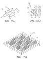
- Metal foil 19 is comprised of a plurality of tabs 17 arranged in a repeating pattern. Each tab 17 has a base end 11, a terminus end 13 and a tab shaft 15 extending from the base end 11 to the terminus end 13. Tab shafts 15 of Fig. 1(a) bend at an approximate right angle while the tabs 17 of Fig. 1(b) are generally linear in construction and extend primarily straight from base end 11 to terminus end 13.
- the shape of the tabs 17 determines the geometry of, and hence the aerodynamic and heat transfer performance of, the cooling passages so formed. Therefore, while illustrated herein with respect to two preferred tab geometries, any tab geometry suitable to produce a cooling passage possessing desirable heat transfer characteristics and aerodynamic performance could be used.
- each tab shaft 15 extends away from the predominantly planar surface of the base core 10 in a generally uniform manner, although the present invention is not limited to such a uniform manner.
- Equiax, directionally-solidified, and single-crystal nickel and cobalt super-alloys are typically used to form operative parts including, but not limited to, combustor liner panels and hot-section turbine component castings.
- these components are investment (or negative-gravity) or controlled-solidification cast using wax positives made in tooling dies.
- the tooling dies are machined aluminum (or alternative material) with compensation for shrinkage, gating, and venting.
- the tooling dies are sealed and injected with a molding substance, typically wax, to form the part.
- the tooling die is then removed and the wax part is subsequently built-up with pre-coat and shelling material/stucco to form a shell around the operative part.
- the wax is evacuated from the shell to form the mold for the metal part.
- the tooling die is modified and grown in size to accommodate the coated base core.
- the base core is situated in the tooling die so as to rest generally flush with an inner surface of the tooling die and the wax is injected about the base core.
- the tooling die may also be modified to have datum/attachment pins or holes to secure the base core in the tooling die.
- Alternative methods of fabricated wax parts molds, including rapid prototype means, can also be adjusted to accommodate these base cores.
- Conventional cores may also be incorporated into the tooling die in conjunction with this type of base core. Following the casting procedure, the core will be removed by chemical removal, thermal leaching, or oxidation methods.
- FIG. 2 there is illustrated a cross-sectional view of the base core 10 after removal from the tooling die and the subsequent shelling procedure but prior to casting.
- each tab 17 is angularly displaced from the base core 10 by an angle theta.
- a protective coating 21 is applied to the surface of base core 10 prior to any bending of the base core 10 to mate with the tooling die.
- Protective coating 21 prevents the dissolution and oxidation of the refractory metal core 10, particularly at elevated temperatures encountered during casting, as well as provides a desired surface quality of the part.
- Base core 10 is of sufficient rigidity to function as a structural hard back-core.
- hard back-core refers to a component which gives shape and structural support during the casting process.
- the base core 10 of the present invention can function as a hard back core.
- base core 10 is mated to the inner surface of a tooling die while molding substance is injected into the tooling die to cover the inward facing surface of the base core 10.
- a preferred molding substance is wax but may be any substance capable of holding its form during the shelling process and capable of removal thereafter. The molding substance is injected to form molding layer 25 in such a manner as to surround each tab 17 while allowing each tab 17 to extend through molding layer 25.
- the molding substance After the molding substance has been injected and allowed to harden, the molding substance is removed from the tooling die.
- the coated base core 10 and the surrounding molding layer 25 is subsequently built-up with pre-coat and shelling material/stucco layers to form a shell 23 around the operative part, after which the shell may be hardened, e.g., by heating.
- the molding layer 25 is then evacuated from the shell 23 to form the mold for the operative part.
- Metal is then injected into the evacuated shell 23 and the shell 23 removed resulting in a cast operative part in contact with the base core 10 and through which protrudes a plurality of tabs 17.
- FIG. 3 there is illustrated a perspective view of a post-casting operative part after core removal.
- the cores in this invention can be tailored to meet performance requirements of a particular component design.
- cores can be very small, thin, shaped, and the tabs bent to optimize cooling performance as well as to control flow losses/discharge coefficients.
- Tabs can be arranged in a repeatable, prescribed or tailored configuration at densities and orientation commensurate with requirements of cooling the cast part. This can reduce cooling requirements and alleviate material temperature requirements.
- the bent tab features allow cooling to be incorporated at locations that are difficult to cool presently. Such locations include, but are not limited to, spaces between attachment studs/hooks and the exposed surface of combustor panels; near rails, component edges, and grommets.
- cooling passages are inherent to the operative part and post-processing operations including laser drilling of cooling holes are no longer needed or are streamlined.
- cooling channel/hole recast attributed to laser drilling and EDM which can contribute to premature crack formation and reduced durability/life, is eliminated.
- the consistency of the hole shapes is also improved.
- the core provides strength and form during shelling. As a result, part shapes and tolerances are better maintained during casting, so yields are improved and post-casting part rework is eliminated.
Landscapes
- Engineering & Computer Science (AREA)
- Mechanical Engineering (AREA)
- Molds, Cores, And Manufacturing Methods Thereof (AREA)
Abstract
Description
Claims (18)
- A base core (10) for use in casting cooling passages in a workpiece comprising:wherein each of said tabs is independently angularly displaceable about each said base end of said tabs and wherein said base core is bent to form a hard back core.a metal strip (19) comprising a generally planar expanse;a plurality of tabs (17) arranged in a pattern upon said metal strip each of said tabs comprising:a base end;a terminus end (13); anda tab shaft (15) extending from said base endto said terminus end;
- The base core (10) of claim 1, wherein said tab shafts (15) extend in a generally linear manner.
- The base core (10) of claim 1, wherein said tab shafts (15) extend from one of said base ends (11) to a corresponding one of said terminus ends (13) in a nonlinear manner.
- The base core (10) of claim 1, 2 or 3, wherein said metal strip (19) comprises a refractory metal.
- The base core (10) of claim 4, wherein said refractory metal is selected from the group consisting of molybdenum and tungsten.
- The base core of any preceding claim, wherein said tabs (17) are formed via laser machining.
- The base core of any of claims 1 to 5, wherein said tabs (17) are formed by photoetching.
- The base core (10) of any one of claims 1 to 5, wherein said tabs (17) are formed by chemical etching.
- The base core (10) of any one of claims 1 to 5, wherein said tabs (17) are formed by direct casting.
- The base core (10) of any of claims 1 to 5, wherein said tabs (17) are formed by machining.
- The base core (10) of any of claims 1 to 5, wherein said tabs (17) are formed by punch pressing.
- The base core of any preceding claim, wherein said workpiece is selected from the group consisting of turbines, combustors liners, panels, heat shields, fuel-air systems, turbine airfoils, vanes, air seals, endwalls, platforms, and gas turbine exhaust components.
- A method for casting a workpiece comprising the steps of:applying a protective coating (21) to a base core (10) said base core comprising:a metal strip (19) comprising a generally planar expanse;a plurality of tabs (17) arranged in a pattern upon said metal strip each of said tabs comprising:wherein each of said tabs is angularly displaced about each said base end of said tabs;a base end (11) ;a terminus end (13); anda tab shaft (15) extending from said base end to said terminus end;injecting a molding substance about said tabs of said base core;
encapsulating said base core in a shell (23);
removing said molding substance;
casting about said base core; and
removing said base core. - The method of claim 13 comprising the additional steps of:mating said base core (10) with a surface of a tooling die prior to said injecting of said molding substance; andremoving said tooling die.
- The method of claim 14 comprising the additional step of bending said base core (10) to fit flush with said surface of said tooling die.
- The method of claim 15 comprising the additional step of securing said base core (10) to said surface of said tooling die using attachment pins.
- The method of any of claims 13 to 16, wherein said base core (10) forms a hard back core.
- The method of any of claims 13 to 17, wherein said workpiece is selected from the group consisting of turbines, combustors liners, panels, heat shields, fuel-air systems, turbine airfoils, vanes, air seals, endwalls, platforms, and gas turbine exhaust components.
Applications Claiming Priority (2)
| Application Number | Priority Date | Filing Date | Title |
|---|---|---|---|
| US135059 | 1998-08-18 | ||
| US10/135,059 US6668906B2 (en) | 2002-04-29 | 2002-04-29 | Shaped core for cast cooling passages and enhanced part definition |
Publications (2)
| Publication Number | Publication Date |
|---|---|
| EP1358954A1 true EP1358954A1 (en) | 2003-11-05 |
| EP1358954B1 EP1358954B1 (en) | 2008-01-09 |
Family
ID=29215637
Family Applications (1)
| Application Number | Title | Priority Date | Filing Date |
|---|---|---|---|
| EP03252688A Expired - Lifetime EP1358954B1 (en) | 2002-04-29 | 2003-04-29 | Shaped core for cast cooling passages and enhanced part definition |
Country Status (7)
| Country | Link |
|---|---|
| US (1) | US6668906B2 (en) |
| EP (1) | EP1358954B1 (en) |
| JP (1) | JP4057463B2 (en) |
| CN (1) | CN1253273C (en) |
| AT (1) | ATE383211T1 (en) |
| DE (1) | DE60318515T2 (en) |
| MX (1) | MXPA03003726A (en) |
Cited By (12)
| Publication number | Priority date | Publication date | Assignee | Title |
|---|---|---|---|---|
| EP1524046A1 (en) * | 2003-10-15 | 2005-04-20 | United Technologies Corporation | Refactory metal core |
| EP1531019A1 (en) * | 2003-10-16 | 2005-05-18 | United Technologies Corporation | Refractory metal core wall thickness control |
| EP1543896A2 (en) | 2003-12-19 | 2005-06-22 | United Technologies Corporation | Investment casting cores |
| EP1611978A1 (en) * | 2004-06-14 | 2006-01-04 | United Technologies Corporation | Investment casting |
| EP1616642A1 (en) * | 2004-07-14 | 2006-01-18 | United Technologies Corporation | Investment casting |
| EP1524045A3 (en) * | 2003-10-15 | 2006-12-27 | United Technologies Corporation | Refractory metal core |
| EP1769861A3 (en) * | 2005-09-19 | 2007-04-11 | United Technologies Corporation | Manufacture of casting cores |
| EP1815923A1 (en) * | 2006-01-30 | 2007-08-08 | United Technologies Corporation | Metallic coated cores to facilitate thin wall casting |
| EP1760402A3 (en) * | 2005-08-30 | 2009-11-11 | United Technologies Corporation | Method for casting cooling holes |
| CH700320A1 (en) * | 2009-01-30 | 2010-07-30 | Alstom Technology Ltd | Method for producing a component of a gas turbine. |
| EP2223753A1 (en) | 2009-02-17 | 2010-09-01 | United Technologies Corporation | Process and refractory metal core for creating varying thickness microcircuits for turbine engine components |
| CN102489668A (en) * | 2011-12-06 | 2012-06-13 | 辽宁速航特铸材料有限公司 | Method for solving cracking of ceramic core by pre-burying fire-resistant rope |
Families Citing this family (14)
| Publication number | Priority date | Publication date | Assignee | Title |
|---|---|---|---|---|
| US7144220B2 (en) * | 2004-07-30 | 2006-12-05 | United Technologies Corporation | Investment casting |
| US7207374B2 (en) * | 2004-10-26 | 2007-04-24 | United Technologies Corporation | Non-oxidizable coating |
| US7207373B2 (en) * | 2004-10-26 | 2007-04-24 | United Technologies Corporation | Non-oxidizable coating |
| US7744347B2 (en) * | 2005-11-08 | 2010-06-29 | United Technologies Corporation | Peripheral microcircuit serpentine cooling for turbine airfoils |
| US7882885B2 (en) * | 2008-02-18 | 2011-02-08 | United Technologies Corporation | Systems and methods for reducing the potential for riser backfilling during investment casting |
| US7942188B2 (en) * | 2008-03-12 | 2011-05-17 | Vent-Tek Designs, Llc | Refractory metal core |
| US9057523B2 (en) | 2011-07-29 | 2015-06-16 | United Technologies Corporation | Microcircuit cooling for gas turbine engine combustor |
| GB201508795D0 (en) * | 2015-05-22 | 2015-07-01 | Rolls Royce Plc | Cooling of turbine blades |
| CN105436838B (en) * | 2015-11-05 | 2018-02-23 | 西安航空动力股份有限公司 | A kind of moving turbine blade machining process |
| EP3429779B1 (en) * | 2016-03-18 | 2020-06-03 | Siemens Aktiengesellschaft | Manufacturing method and tooling for ceramic cores |
| US20180161852A1 (en) * | 2016-12-13 | 2018-06-14 | General Electric Company | Integrated casting core-shell structure with printed tubes for making cast component |
| US10619852B2 (en) * | 2017-08-25 | 2020-04-14 | United Technologies Corporation | Heat shield with round top pin fins and flat top pin fins for improved manufacturing processes |
| US10927705B2 (en) * | 2018-08-17 | 2021-02-23 | Raytheon Technologies Corporation | Method for forming cooling holes having separate complex and simple geometry sections |
| US10953461B2 (en) * | 2019-03-21 | 2021-03-23 | Raytheon Technologies Corporation | Investment casting method including forming of investment casting core |
Citations (4)
| Publication number | Priority date | Publication date | Assignee | Title |
|---|---|---|---|---|
| US3957104A (en) * | 1974-02-27 | 1976-05-18 | The United States Of America As Represented By The Administrator Of The United States National Aeronautics And Space Administration | Method of making an apertured casting |
| US4729162A (en) * | 1986-06-11 | 1988-03-08 | Duracell Inc. | Electrochemical cell asssembly |
| DE19831149A1 (en) * | 1998-07-11 | 2000-01-13 | Buderus Guss Gmbh | Producing castings, in particular, parts of turbine housings with use of non-meltable cores and form elements |
| WO2000061314A1 (en) * | 1999-04-07 | 2000-10-19 | Steel Foundations Technology Pty. Ltd. | A helical flyte for screw pile anchors |
Family Cites Families (1)
| Publication number | Priority date | Publication date | Assignee | Title |
|---|---|---|---|---|
| DE1929898A1 (en) * | 1969-06-12 | 1970-12-23 | Ludwig Foebus Kg | Box stud for moulds |
-
2002
- 2002-04-29 US US10/135,059 patent/US6668906B2/en not_active Expired - Lifetime
-
2003
- 2003-04-28 MX MXPA03003726A patent/MXPA03003726A/en not_active Application Discontinuation
- 2003-04-29 CN CNB031407579A patent/CN1253273C/en not_active Expired - Fee Related
- 2003-04-29 EP EP03252688A patent/EP1358954B1/en not_active Expired - Lifetime
- 2003-04-29 DE DE60318515T patent/DE60318515T2/en not_active Expired - Lifetime
- 2003-04-29 AT AT03252688T patent/ATE383211T1/en not_active IP Right Cessation
- 2003-04-30 JP JP2003125611A patent/JP4057463B2/en not_active Expired - Fee Related
Patent Citations (4)
| Publication number | Priority date | Publication date | Assignee | Title |
|---|---|---|---|---|
| US3957104A (en) * | 1974-02-27 | 1976-05-18 | The United States Of America As Represented By The Administrator Of The United States National Aeronautics And Space Administration | Method of making an apertured casting |
| US4729162A (en) * | 1986-06-11 | 1988-03-08 | Duracell Inc. | Electrochemical cell asssembly |
| DE19831149A1 (en) * | 1998-07-11 | 2000-01-13 | Buderus Guss Gmbh | Producing castings, in particular, parts of turbine housings with use of non-meltable cores and form elements |
| WO2000061314A1 (en) * | 1999-04-07 | 2000-10-19 | Steel Foundations Technology Pty. Ltd. | A helical flyte for screw pile anchors |
Cited By (21)
| Publication number | Priority date | Publication date | Assignee | Title |
|---|---|---|---|---|
| EP1524046A1 (en) * | 2003-10-15 | 2005-04-20 | United Technologies Corporation | Refactory metal core |
| EP1524045A3 (en) * | 2003-10-15 | 2006-12-27 | United Technologies Corporation | Refractory metal core |
| US7575039B2 (en) | 2003-10-15 | 2009-08-18 | United Technologies Corporation | Refractory metal core coatings |
| EP2060339A1 (en) * | 2003-10-15 | 2009-05-20 | United Technologies Corporation | Refractory metal core |
| EP1531019A1 (en) * | 2003-10-16 | 2005-05-18 | United Technologies Corporation | Refractory metal core wall thickness control |
| EP1543896A2 (en) | 2003-12-19 | 2005-06-22 | United Technologies Corporation | Investment casting cores |
| EP2295166A1 (en) * | 2003-12-19 | 2011-03-16 | United Technologies Corporation | Investment casting cores |
| EP1543896A3 (en) * | 2003-12-19 | 2006-02-01 | United Technologies Corporation | Investment casting cores |
| EP1611978A1 (en) * | 2004-06-14 | 2006-01-04 | United Technologies Corporation | Investment casting |
| US7520312B2 (en) * | 2004-07-14 | 2009-04-21 | United Technologies Corporation | Investment casting |
| EP1616642A1 (en) * | 2004-07-14 | 2006-01-18 | United Technologies Corporation | Investment casting |
| EP1760402A3 (en) * | 2005-08-30 | 2009-11-11 | United Technologies Corporation | Method for casting cooling holes |
| CN100418665C (en) * | 2005-09-19 | 2008-09-17 | 联合工艺公司 | Manufacture of casting cores |
| EP1769861A3 (en) * | 2005-09-19 | 2007-04-11 | United Technologies Corporation | Manufacture of casting cores |
| EP1815923A1 (en) * | 2006-01-30 | 2007-08-08 | United Technologies Corporation | Metallic coated cores to facilitate thin wall casting |
| CH700320A1 (en) * | 2009-01-30 | 2010-07-30 | Alstom Technology Ltd | Method for producing a component of a gas turbine. |
| WO2010086402A3 (en) * | 2009-01-30 | 2010-10-21 | Alstom Technology Ltd. | Method for producing a component of a gas turbine |
| EP2223753A1 (en) | 2009-02-17 | 2010-09-01 | United Technologies Corporation | Process and refractory metal core for creating varying thickness microcircuits for turbine engine components |
| US8347947B2 (en) | 2009-02-17 | 2013-01-08 | United Technologies Corporation | Process and refractory metal core for creating varying thickness microcircuits for turbine engine components |
| US9038700B2 (en) | 2009-02-17 | 2015-05-26 | United Technologies Corporation | Process and refractory metal core for creating varying thickness microcircuits for turbine engine components |
| CN102489668A (en) * | 2011-12-06 | 2012-06-13 | 辽宁速航特铸材料有限公司 | Method for solving cracking of ceramic core by pre-burying fire-resistant rope |
Also Published As
| Publication number | Publication date |
|---|---|
| ATE383211T1 (en) | 2008-01-15 |
| DE60318515T2 (en) | 2008-12-24 |
| JP4057463B2 (en) | 2008-03-05 |
| CN1460565A (en) | 2003-12-10 |
| US6668906B2 (en) | 2003-12-30 |
| JP2003340548A (en) | 2003-12-02 |
| CN1253273C (en) | 2006-04-26 |
| DE60318515D1 (en) | 2008-02-21 |
| US20030201089A1 (en) | 2003-10-30 |
| EP1358954B1 (en) | 2008-01-09 |
| MXPA03003726A (en) | 2004-12-06 |
Similar Documents
| Publication | Publication Date | Title |
|---|---|---|
| EP1358954B1 (en) | Shaped core for cast cooling passages and enhanced part definition | |
| US4574451A (en) | Method for producing an article with a fluid passage | |
| CA2408815C (en) | Cores for use in precision investment casting | |
| EP1495820B1 (en) | Investment casting method | |
| EP2509726B1 (en) | Investment casting utilizing flexible wax pattern tool | |
| US8251123B2 (en) | Casting core assembly methods | |
| US4422229A (en) | Method of making an airfoil member for a gas turbine engine | |
| US10184353B2 (en) | Blade outer air seal cooling scheme | |
| JP2008279506A (en) | Investment casting core combination, pattern, shell, core assembly and method for forming core | |
| JP2007301636A (en) | Investment casting method and method for manufacturing investment casting core | |
| EP1614488B1 (en) | Casting method using a synthetic model produced by stereolithography | |
| EP3381582B1 (en) | Method of making complex internal passages in turbine airfoils | |
| EP3210693B1 (en) | Manufacturing process of a component formed around a first metal component using hot isostatic pressing | |
| KR20170122676A (en) | Method and assembly for forming components using a jacketed core | |
| EP0113883A2 (en) | Article with a fluid passage and method for making | |
| EP3959024B1 (en) | Investment casting core with cooling feature alignment guide and related methods |
Legal Events
| Date | Code | Title | Description |
|---|---|---|---|
| PUAI | Public reference made under article 153(3) epc to a published international application that has entered the european phase |
Free format text: ORIGINAL CODE: 0009012 |
|
| AK | Designated contracting states |
Kind code of ref document: A1 Designated state(s): AT BE BG CH CY CZ DE DK EE ES FI FR GB GR HU IE IT LI LU MC NL PT RO SE SI SK TR |
|
| AX | Request for extension of the european patent |
Extension state: AL LT LV MK |
|
| 17P | Request for examination filed |
Effective date: 20040504 |
|
| AKX | Designation fees paid |
Designated state(s): AT BE BG CH CY CZ DE DK EE ES FI FR GB GR HU IE IT LI LU MC NL PT RO SE SI SK TR |
|
| GRAP | Despatch of communication of intention to grant a patent |
Free format text: ORIGINAL CODE: EPIDOSNIGR1 |
|
| GRAS | Grant fee paid |
Free format text: ORIGINAL CODE: EPIDOSNIGR3 |
|
| GRAA | (expected) grant |
Free format text: ORIGINAL CODE: 0009210 |
|
| AK | Designated contracting states |
Kind code of ref document: B1 Designated state(s): AT BE BG CH CY CZ DE DK EE ES FI FR GB GR HU IE IT LI LU MC NL PT RO SE SI SK TR |
|
| REG | Reference to a national code |
Ref country code: GB Ref legal event code: FG4D |
|
| REG | Reference to a national code |
Ref country code: CH Ref legal event code: EP |
|
| REG | Reference to a national code |
Ref country code: IE Ref legal event code: FG4D |
|
| REF | Corresponds to: |
Ref document number: 60318515 Country of ref document: DE Date of ref document: 20080221 Kind code of ref document: P |
|
| PG25 | Lapsed in a contracting state [announced via postgrant information from national office to epo] |
Ref country code: NL Free format text: LAPSE BECAUSE OF FAILURE TO SUBMIT A TRANSLATION OF THE DESCRIPTION OR TO PAY THE FEE WITHIN THE PRESCRIBED TIME-LIMIT Effective date: 20080109 Ref country code: SI Free format text: LAPSE BECAUSE OF FAILURE TO SUBMIT A TRANSLATION OF THE DESCRIPTION OR TO PAY THE FEE WITHIN THE PRESCRIBED TIME-LIMIT Effective date: 20080109 |
|
| NLV1 | Nl: lapsed or annulled due to failure to fulfill the requirements of art. 29p and 29m of the patents act | ||
| PG25 | Lapsed in a contracting state [announced via postgrant information from national office to epo] |
Ref country code: CH Free format text: LAPSE BECAUSE OF FAILURE TO SUBMIT A TRANSLATION OF THE DESCRIPTION OR TO PAY THE FEE WITHIN THE PRESCRIBED TIME-LIMIT Effective date: 20080109 Ref country code: LI Free format text: LAPSE BECAUSE OF FAILURE TO SUBMIT A TRANSLATION OF THE DESCRIPTION OR TO PAY THE FEE WITHIN THE PRESCRIBED TIME-LIMIT Effective date: 20080109 Ref country code: FI Free format text: LAPSE BECAUSE OF FAILURE TO SUBMIT A TRANSLATION OF THE DESCRIPTION OR TO PAY THE FEE WITHIN THE PRESCRIBED TIME-LIMIT Effective date: 20080109 Ref country code: ES Free format text: LAPSE BECAUSE OF FAILURE TO SUBMIT A TRANSLATION OF THE DESCRIPTION OR TO PAY THE FEE WITHIN THE PRESCRIBED TIME-LIMIT Effective date: 20080420 |
|
| REG | Reference to a national code |
Ref country code: CH Ref legal event code: PL |
|
| PG25 | Lapsed in a contracting state [announced via postgrant information from national office to epo] |
Ref country code: BG Free format text: LAPSE BECAUSE OF FAILURE TO SUBMIT A TRANSLATION OF THE DESCRIPTION OR TO PAY THE FEE WITHIN THE PRESCRIBED TIME-LIMIT Effective date: 20080409 Ref country code: AT Free format text: LAPSE BECAUSE OF FAILURE TO SUBMIT A TRANSLATION OF THE DESCRIPTION OR TO PAY THE FEE WITHIN THE PRESCRIBED TIME-LIMIT Effective date: 20080109 |
|
| PG25 | Lapsed in a contracting state [announced via postgrant information from national office to epo] |
Ref country code: PT Free format text: LAPSE BECAUSE OF FAILURE TO SUBMIT A TRANSLATION OF THE DESCRIPTION OR TO PAY THE FEE WITHIN THE PRESCRIBED TIME-LIMIT Effective date: 20080609 Ref country code: BE Free format text: LAPSE BECAUSE OF FAILURE TO SUBMIT A TRANSLATION OF THE DESCRIPTION OR TO PAY THE FEE WITHIN THE PRESCRIBED TIME-LIMIT Effective date: 20080109 |
|
| EN | Fr: translation not filed | ||
| PG25 | Lapsed in a contracting state [announced via postgrant information from national office to epo] |
Ref country code: CZ Free format text: LAPSE BECAUSE OF FAILURE TO SUBMIT A TRANSLATION OF THE DESCRIPTION OR TO PAY THE FEE WITHIN THE PRESCRIBED TIME-LIMIT Effective date: 20080109 Ref country code: DK Free format text: LAPSE BECAUSE OF FAILURE TO SUBMIT A TRANSLATION OF THE DESCRIPTION OR TO PAY THE FEE WITHIN THE PRESCRIBED TIME-LIMIT Effective date: 20080109 Ref country code: SE Free format text: LAPSE BECAUSE OF FAILURE TO SUBMIT A TRANSLATION OF THE DESCRIPTION OR TO PAY THE FEE WITHIN THE PRESCRIBED TIME-LIMIT Effective date: 20080409 Ref country code: SK Free format text: LAPSE BECAUSE OF FAILURE TO SUBMIT A TRANSLATION OF THE DESCRIPTION OR TO PAY THE FEE WITHIN THE PRESCRIBED TIME-LIMIT Effective date: 20080109 |
|
| PLBE | No opposition filed within time limit |
Free format text: ORIGINAL CODE: 0009261 |
|
| STAA | Information on the status of an ep patent application or granted ep patent |
Free format text: STATUS: NO OPPOSITION FILED WITHIN TIME LIMIT |
|
| PG25 | Lapsed in a contracting state [announced via postgrant information from national office to epo] |
Ref country code: RO Free format text: LAPSE BECAUSE OF FAILURE TO SUBMIT A TRANSLATION OF THE DESCRIPTION OR TO PAY THE FEE WITHIN THE PRESCRIBED TIME-LIMIT Effective date: 20080109 Ref country code: MC Free format text: LAPSE BECAUSE OF NON-PAYMENT OF DUE FEES Effective date: 20080430 |
|
| 26N | No opposition filed |
Effective date: 20081010 |
|
| PG25 | Lapsed in a contracting state [announced via postgrant information from national office to epo] |
Ref country code: EE Free format text: LAPSE BECAUSE OF FAILURE TO SUBMIT A TRANSLATION OF THE DESCRIPTION OR TO PAY THE FEE WITHIN THE PRESCRIBED TIME-LIMIT Effective date: 20080109 |
|
| PG25 | Lapsed in a contracting state [announced via postgrant information from national office to epo] |
Ref country code: FR Free format text: LAPSE BECAUSE OF FAILURE TO SUBMIT A TRANSLATION OF THE DESCRIPTION OR TO PAY THE FEE WITHIN THE PRESCRIBED TIME-LIMIT Effective date: 20081031 Ref country code: IE Free format text: LAPSE BECAUSE OF NON-PAYMENT OF DUE FEES Effective date: 20080429 |
|
| PG25 | Lapsed in a contracting state [announced via postgrant information from national office to epo] |
Ref country code: CY Free format text: LAPSE BECAUSE OF FAILURE TO SUBMIT A TRANSLATION OF THE DESCRIPTION OR TO PAY THE FEE WITHIN THE PRESCRIBED TIME-LIMIT Effective date: 20080109 |
|
| PG25 | Lapsed in a contracting state [announced via postgrant information from national office to epo] |
Ref country code: IT Free format text: LAPSE BECAUSE OF FAILURE TO SUBMIT A TRANSLATION OF THE DESCRIPTION OR TO PAY THE FEE WITHIN THE PRESCRIBED TIME-LIMIT Effective date: 20080109 |
|
| PG25 | Lapsed in a contracting state [announced via postgrant information from national office to epo] |
Ref country code: LU Free format text: LAPSE BECAUSE OF NON-PAYMENT OF DUE FEES Effective date: 20080429 Ref country code: HU Free format text: LAPSE BECAUSE OF FAILURE TO SUBMIT A TRANSLATION OF THE DESCRIPTION OR TO PAY THE FEE WITHIN THE PRESCRIBED TIME-LIMIT Effective date: 20080710 |
|
| PG25 | Lapsed in a contracting state [announced via postgrant information from national office to epo] |
Ref country code: TR Free format text: LAPSE BECAUSE OF FAILURE TO SUBMIT A TRANSLATION OF THE DESCRIPTION OR TO PAY THE FEE WITHIN THE PRESCRIBED TIME-LIMIT Effective date: 20080109 |
|
| PG25 | Lapsed in a contracting state [announced via postgrant information from national office to epo] |
Ref country code: GR Free format text: LAPSE BECAUSE OF FAILURE TO SUBMIT A TRANSLATION OF THE DESCRIPTION OR TO PAY THE FEE WITHIN THE PRESCRIBED TIME-LIMIT Effective date: 20080410 |
|
| REG | Reference to a national code |
Ref country code: DE Ref legal event code: R082 Ref document number: 60318515 Country of ref document: DE Representative=s name: SCHMITT-NILSON SCHRAUD WAIBEL WOHLFROM PATENTA, DE |
|
| REG | Reference to a national code |
Ref country code: DE Ref legal event code: R082 Ref document number: 60318515 Country of ref document: DE Representative=s name: SCHMITT-NILSON SCHRAUD WAIBEL WOHLFROM PATENTA, DE Ref country code: DE Ref legal event code: R081 Ref document number: 60318515 Country of ref document: DE Owner name: UNITED TECHNOLOGIES CORP. (N.D.GES.D. STAATES , US Free format text: FORMER OWNER: UNITED TECHNOLOGIES CORPORATION, EAST HARTFORD, CONN., US |
|
| PGFP | Annual fee paid to national office [announced via postgrant information from national office to epo] |
Ref country code: GB Payment date: 20200323 Year of fee payment: 18 |
|
| PGFP | Annual fee paid to national office [announced via postgrant information from national office to epo] |
Ref country code: DE Payment date: 20200319 Year of fee payment: 18 |
|
| REG | Reference to a national code |
Ref country code: DE Ref legal event code: R119 Ref document number: 60318515 Country of ref document: DE |
|
| GBPC | Gb: european patent ceased through non-payment of renewal fee |
Effective date: 20210429 |
|
| PG25 | Lapsed in a contracting state [announced via postgrant information from national office to epo] |
Ref country code: GB Free format text: LAPSE BECAUSE OF NON-PAYMENT OF DUE FEES Effective date: 20210429 Ref country code: DE Free format text: LAPSE BECAUSE OF NON-PAYMENT OF DUE FEES Effective date: 20211103 |