EP1358814A1 - One piece adjustable ring - Google Patents
One piece adjustable ring Download PDFInfo
- Publication number
- EP1358814A1 EP1358814A1 EP02253071A EP02253071A EP1358814A1 EP 1358814 A1 EP1358814 A1 EP 1358814A1 EP 02253071 A EP02253071 A EP 02253071A EP 02253071 A EP02253071 A EP 02253071A EP 1358814 A1 EP1358814 A1 EP 1358814A1
- Authority
- EP
- European Patent Office
- Prior art keywords
- ring
- shank
- bracelet
- band
- adjustable ring
- Prior art date
- Legal status (The legal status is an assumption and is not a legal conclusion. Google has not performed a legal analysis and makes no representation as to the accuracy of the status listed.)
- Withdrawn
Links
Images

Classifications
-
- A—HUMAN NECESSITIES
- A44—HABERDASHERY; JEWELLERY
- A44C—PERSONAL ADORNMENTS, e.g. JEWELLERY; COINS
- A44C9/00—Finger-rings
- A44C9/02—Finger-rings adjustable
Definitions
- the present invention relates to ornamental jewelry such as a ring worn around a finger and a bracelet worn around a wrist or ankle, and, more particularly, to a one-piece adjustable size ring or bracelet.
- the goal of properly sizing a finger ring is to provide a smug, comfortable fit which allows the ring to be easily placed and removed from a wearer's finger, feel comfortable to the wearer, and not unintentionally slide off of the wearer's finger.
- Rings are initially sized to fit a particular finger of one wearer. However, if the physical characteristics of the wearer change, such as through weight gain or loss or other growth of the wearer, or if the wearer desires to wear the ring on a different-sized finger or give the ring to another person with different-sized fingers, the ring would either be too narrow and tight or too wide and loose to be worn properly, if at all.
- One method for altering the size of a ring involves cutting and removing a portion of the shank of the ring, This process leaves an opening in the shank with two ends. Once the portion is removed, the shank is subjected to either; 1) compression, forcing the two ends together and then joining them, forming a smaller-sized ring; or 2) expansion, forcing the two ends further apart and then joining a new, larger piece of material between them, forming a larger-sized ring.
- This is an expensive method which requires mutilation of the ring, ruining its aesthetic beauty and decreasing its value. It also requires repeated mutilation if further adjustments in size are required.
- U.S. Patent No. 4,223,541 discloses a ring having an adjusting band enclosed and movable within an interior slot in the shank.
- U.S. Patent No. 4,158,951 discloses a ring having a mesh band with a clasp secured to one end of it, the band being capable of forming a loop and locked by the clasp.
- U.S. Patent No. 3,460,356 discloses a device with a main band and an auxiliary band on the inner surface of the main band with a means for narrowing the diameter of the auxiliary band.
- Other sizing devices such as that in U.S. Patent No.
- U.S. Patent No. 3,236,065 discloses a moveable shank element located within a channel of an ornamental portion of the ring.
- a ring comprising a shank with an adjustment structure that facilitates the easy stretching and compressing of the interior of the ring to fit a variety of finger sizes.
- the shank is constructed of a single piece of material.
- the adjustment structure is an integral part of the shank and is formed within the same piece of material that comprises the shank. As such, no additional parts are required. Thus, there are no small parts which may be difficult to work with, easily broken, complex to assemble or detract from the aesthetic beauty of the ring.
- the ornamental ring of the present invention is constructed of a single piece of material, such as silver, gold, brass, bronze, platinum or other metal or alloy.
- the material used to construct the ring of the present invention is substantially rigid, such that it will not significantly deform during normal usage.
- the material used is also sufficiently malleable to the extent that when sufficient stretching or compressive force is placed upon the adjustment structure, it will expand or contract to reach the desired size. Once it has reach the desired size and the force has been released, the ring will maintain the new size.
- the adjustment device of the present invention facilitates the continuously variable expansion and contraction of the shank over a wide range of sizes.
- the adjustment structure is spring-like or accordion-like in its configuration having the shape of a helix, sawtooth pattern, or other regularly repeating configuration. It provides the shank of the ring with an excess amount of material configured so that it may be coiled in contraction or spread in extension.
- one preferred embodiment of a ring in accordance with the present invention has a substantially round shank 10, an adjustment structure 20, and a setting or jewel retaining structure 30.
- the shank 10 is defined by a body 12 having an interior surface 14, exterior surface 16, and two opposing side surfaces 18.
- the circumference of the interior surface 14 corresponds to the size of the finger upon which the ring is to be worn.
- the side surfaces 18 may be substantially parallel to each other, or may narrow subject to the aesthetic and stylistic considerations of the design of the ring.
- the adjustment structure 20 is integrally formed with, and forms part of the shank 10.
- the adjustment structure 20 is located along the bottom of shank 10, that is, at the opposite side of the shank 10 from the setting 30.
- the adjustment structure may be positioned at other places along the shank 10, including directly under the setting 30.
- positioning of the adjustment structure 30 at the bottom of the shank 10 shields the structure 20 from view and helps to prevent the shank 10 from turning about the wearer's finger, as explained further below.
- the adjustment structure 20 is an accordion- or spring-like structure having a sawtooth design which can expand and contract under the influence of pressure.
- pressure is applied by forcing the ring onto a ring roller or expander, such as a conventional roller or expander as known to those of skill in the art, which then exerts substantially equally distributed force onto the interior surface 14.
- a ring roller or expander such as a conventional roller or expander as known to those of skill in the art, which then exerts substantially equally distributed force onto the interior surface 14.
- There interior surface expands in circumference by stretching the spring-like adjustment structure 20.
- pressure is applied by squeezing the shank 10 on opposing sides of the exterior surface 16 at points which are equidistant to the opposing ends of the adjustment structure 20, thus compressing the structure 20.
- the adjustment structure 20 will expand or contract substantially more than the rest of the shank 10 as will be recognized by one of skill in the art.
- the shank 10 may be expanded or contracted by the application of pressure onto either the grooves or troughs 21A of the adjustment structure 20, to contract the adjustment structure, or the peaks 21B, to expand the structure.
- This pressure is preferably applied substantially equally to all grooves 21A or peaks 21B in the adjustment structure 20 to contract or expand the adjustment structure in a uniform manner.
- the corrugations 22 of the adjustment structure 20 extend within the interior of the shank 10 and beyond the exterior surface 16 of the shank 10.
- the corrugations 22 are movingly adjustable along the interior surface 14 and the exterior surface 16.
- the corrugations 22 are in maximum compression.
- the corrugations 22 are in maximum extension.
- the ring size may be configured in a continuously variable manner within the range of the smallest and largest circumferencial size of the interior surface 14.
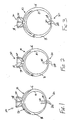
- Figs. 1-3 show a ring at different sizes.
- Fig. 1 shows a preferred embodiment with the adjustment structure 20 having corrugations 22 being near maximum compression and the ring having a size of 5.
- the interior surface 14 is configured such that it is near its smallest size.
- Fig. 2 shows the preferred embodiment of Fig. 1 with the adjustment structure 20 having corrugations 22 being between full extension and full compression, at a ring size of a about 7.
- the interior surface 14 is configured such that it is at a moderate size between its maximum and minimum sizes.
- Fig, 3 shows the preferred embodiment of Fig. 1 with the adjustment structure 20 having corrugations 22 being near maximum extension, at ring size of about 9.
- rings may be sized with a range of at least four sizes, two up and two down from a median size, at any level of precision, such as at half-sizes, etc.
- the adjustment structure 20' is comprised of a helical spring design or helix 24.
- the helix 24 is defined as the path followed by a point moving on the surface of a right circular cylinder that moves along the cylinder at a constant ratio as it moves around the cylinder.
- the length of the helix 24 and its radius are inversely proportional. Thus, as length increase, the radius decreases, and as length decreases, the radius increases.
- the helix 24 is located about an imaginary cylinder that substantially runs lengthwise along the interior surface 14 and the exterior surface 16.
- the helix 24 is movingly adjustable along the imaginary cylinder.
- the ring is configured such that interior surface 14 is at its smallest circumferencial size, the helix is in maximum compression.
- the length of the helix 24 is at its minimum and the radius of the helix 24 is at its maximum.
- the helix 24 is in substantially full extension.
- the length of the helix 24 is at its maximum and the radius of the helix 24 is at its minimum (approaching zero).
- Figs. 4-6 show the alternate embodiment of the ring at different sizes.
- Fig. 4 shows the alternate embodiment with the adjustment structure 20' having a helix 24 of large radius and short length. The helix 24 is near full compression. Thus, the interior surface 14 is configured such that it is near its minimum size, with the ring having a size of about 5.
- Fig. 5 shows the alternative embodiment with the adjustment structure 20' having a helix 24 of moderate radius and length. The helix 24 is between full extension and full compression. Thus, the interior surface 14 is configured such that it is at a moderate size between its maximum and minimum sizes, with the ring at a size of about 7.
- Fig. 6 shows a further expanded ring of size about 9 with the helix 24 being stretched to a large length and short radius.
- Over-extension of the adjustment structure is preferably to be avoided.
- Over-extension of adjustment structure 20 causes the material which comprises it to lose its "memory" or ability to return to its previous shape. This would leave the ring permanently in its largest configuration and size. Although this would not destroy the capacity of the ring to be worn, it would adversely effect the ability of the adjustment structure to function, leaving the ring permanently in its largest size configuration.
- the dimensions of preferred embodiments of the designs shown in Figs. 1 and 4 are in the range of about 1 mm to 5 mm for the width of the shank 10 and about 0.5 mm to 2 mm for the thickness of the shank 10.
- the shank 10 is constructed of a substantially rigid yet malleable precious metal or alloy, such as a gold, silver, copper, or an alloy thereof.
- the shank 10 with integrally formed adjustment structure 20 is molded from a die cut in the shape of the shank with adjustment structure 20.
- the die for the shank 10 shown in Fig. 1 is relatively simple and requires only two halves.
- the die for the shank shown in Fig. 4 requires additional pieces to form the hollowed out portion of the helix 24.
- the ring may be unadorned or may have a setting.
- the ring further comprises a setting or jewel retaining structure 30 for retaining jewels or ornaments within the ring.
- the setting 30 can be configured in a variety of ways, or need not be present at all, as in the well-known case of wedding bands.
- the setting 30 comprises a plurality of tines 32 which extend outwardly from the top of exterior surface 16, opposite the adjustment structure 20.
- the tines 32 are arranged such that they may frictionally and joiningly retain a jewel 34.
- the tines 32 are constructed of the same material as the shank 10.
- the corrugations 22 of the accordion-like adjustment structure 20 shown in Fig. 1, the turns of the helix 24 shown in Fig. 4, and the alternating troughs or grooves in both leave opposing temporary impressions in a wearer's finger.
- These impressions help "lock" the adjustment structure 20 in place on the wearer's finger, and prevent the ring from turning or rotating about the finger in an undesired manner or from unintentionally slipping off the wearer's finger.
- the accordion-like structure's surface has up to 70% more contact area with the wearer's finger than a planar portion of the interior surface 14, thus providing a better fit.
- corrugations 22 each have an acute point 23 on the interior surface 14 of the shank 10, which points are sufficiently sharp so as to facilitate additional frictional engagement with the finger of the ring wearer.
- the points 23 are not so sharp as to cause discomfort or injury to the ring wearer.
- the accordion-like adjustment structure 20 may have other designs, such as a regular wavelike design or other designs recognized by those of skill in the art.
- the invention is thus not to be limited to the precise details of methodology or construction set forth above as such variations and modification are intended to be included within the scope of the invention.
Landscapes
- Adornments (AREA)
Abstract
An adjustable ornamental ring or bracelet is constructed of a single piece of
material which is substantially rigid yet malleable under force. The shank of the ring
contains a size adjusting structure (20) integrally formed within the shank. The size
adjusting structure (20) is an accordion or helical spring-like structure positioned at the
bottom of the shank. The adjustment structure (20) may be expanded to increase the
ring size and compressed to contract the ring size.
Description
- A portion of the disclosure of this patent document contains material which is subject to copyright protection. The copyright owner has no objection to the facsimile reproduction by anyone of the patent document or the patent disclosure, as it appears in the Patent and Trademark Office patent files or records, but otherwise reserves all copyright rights whatsoever.
- The present invention relates to ornamental jewelry such as a ring worn around a finger and a bracelet worn around a wrist or ankle, and, more particularly, to a one-piece adjustable size ring or bracelet.
- The goal of properly sizing a finger ring is to provide a smug, comfortable fit which allows the ring to be easily placed and removed from a wearer's finger, feel comfortable to the wearer, and not unintentionally slide off of the wearer's finger. Rings are initially sized to fit a particular finger of one wearer. However, if the physical characteristics of the wearer change, such as through weight gain or loss or other growth of the wearer, or if the wearer desires to wear the ring on a different-sized finger or give the ring to another person with different-sized fingers, the ring would either be too narrow and tight or too wide and loose to be worn properly, if at all.
- One method for altering the size of a ring involves cutting and removing a portion of the shank of the ring, This process leaves an opening in the shank with two ends. Once the portion is removed, the shank is subjected to either; 1) compression, forcing the two ends together and then joining them, forming a smaller-sized ring; or 2) expansion, forcing the two ends further apart and then joining a new, larger piece of material between them, forming a larger-sized ring. This is an expensive method which requires mutilation of the ring, ruining its aesthetic beauty and decreasing its value. It also requires repeated mutilation if further adjustments in size are required.
- Various devices which are separate and removable from the shank of a ring have been disclosed for the adjustment of ring size. These devices include those disclosed in U.S. Patent Nos. 5.239,842, 4.903.507, 4.538.430, 4.480.447, 3.603.109, 3.238.741 and 3.237.426. Such devices are movingly or fixedly attached within the interior of the ring shank and act to effectively decrease the interior circumference of the ring shank.
- These separate and removable devices have the drawback of only being able to effectively decrease the size of a ring, not increase it beyond the size of its initial interior circumference. Further, they have an "added-on" lock which detracts from the aesthetic beauty of the ring and require more parts beyond the shank of the ring itself. Also, some of these external devices are elastic in nature, and are thus prone to dissipation of their elasticity through repeated wearing. Repeated use ultimately renders these external devices weak and useless as sizing devices for rings.
- Other sizing devices, such as that of U.S. Patent No. 5,131,243, have been disclosed wherein a ring shank has spaced apart ends which form an adjustment gap. The ends allow for the expansion and contraction of the shank to very its size. Once a desired size is attained, a cap apparatus is then placed over the shank to lock it in place at the particular size. The small pieces that comprise the cap apparatus are not permanently attached to the shank and are prone to being misplaced. If the pieces are lost, the sizing device is rendered useless. The caps also rain the aesthetic beauty of the shank, and the open-ended characteristic of the shank detracts from its value as a solid piece of metal or alloy.
- Still other sizing devices internal to a ring have been disclosed. U.S. Patent No. 4,223,541, discloses a ring having an adjusting band enclosed and movable within an interior slot in the shank. U.S. Patent No. 4,158,951, discloses a ring having a mesh band with a clasp secured to one end of it, the band being capable of forming a loop and locked by the clasp. U.S. Patent No. 3,460,356 discloses a device with a main band and an auxiliary band on the inner surface of the main band with a means for narrowing the diameter of the auxiliary band. Other sizing devices, such as that in U.S. Patent No. 5,136,858, include latch mechanisms and hinged arcuate sections, which are capable of opening and closing around the wearer's finger, for varying the size of a ring. Another patent, U.S. Patent No. 3,236,065, discloses a moveable shank element located within a channel of an ornamental portion of the ring.
- All of these devices have multiple moving parts within the shank which are small and delicate. Such parts are prone to breakage and to being misplaced and are difficult and expensive to assemble and repair. Some require the machining of openings or cavities in the shank, which adds significant time and expense to the production of the ring shank. It also undermines the structural integrity of the shank and detracts from its value as a solid piece of precious metal or alloy.
- Thus, there is a need for an adjustable finger ring which allows for easy and repeated expansion and contraction of a ring size and which does not contain numerous small parts which are easily lost or broken.
- It is an object of the present invention to solve the problems described above with existing adjustable finger rings.
- It is another object of the invention to provide a one-piece adjustable finger ring.
- It is another object of the present invention to provide a finger ring which is easily adjustable in size without the need to cut any potion of the shank or to otherwise remove or add any material.
- It is another object of the present invention to provide a ring which is easily adjustable in size without the addition of any extraneous parts to the shank or the ring as a whole.
- It is another object of the present invention to provide a ring which may be adjusted to fit a continuous variety of finger sizes.
- It is another object of the present invention to provide an adjustable finger ring which is comfortable and which does not turn upon the wearer's finger.
- The above and other objects are achieved by a ring comprising a shank with an adjustment structure that facilitates the easy stretching and compressing of the interior of the ring to fit a variety of finger sizes. The shank is constructed of a single piece of material. The adjustment structure is an integral part of the shank and is formed within the same piece of material that comprises the shank. As such, no additional parts are required. Thus, there are no small parts which may be difficult to work with, easily broken, complex to assemble or detract from the aesthetic beauty of the ring.
- The ornamental ring of the present invention is constructed of a single piece of material, such as silver, gold, brass, bronze, platinum or other metal or alloy. The material used to construct the ring of the present invention is substantially rigid, such that it will not significantly deform during normal usage. The material used is also sufficiently malleable to the extent that when sufficient stretching or compressive force is placed upon the adjustment structure, it will expand or contract to reach the desired size. Once it has reach the desired size and the force has been released, the ring will maintain the new size.
- The adjustment device of the present invention facilitates the continuously variable expansion and contraction of the shank over a wide range of sizes. In preferred embodiments, the adjustment structure is spring-like or accordion-like in its configuration having the shape of a helix, sawtooth pattern, or other regularly repeating configuration. It provides the shank of the ring with an excess amount of material configured so that it may be coiled in contraction or spread in extension.
- The invention is illustrated in the figures of the accompanying drawings which are meant to be exemplary and not limiting, in which like references refer to like or corresponding parts, and in which:
- Fig. 1 is an elevational view of a ring in accordance with one preferred embodiment of the present invention;
- Fig. 2 is an elevational view of the ring of Fig. 1, shown expanded in size;
- Fig. 3 is an elevational view of the ring of Fig. 1, shown expanded further in size;
- Fig. 4 is an elevational view of an alternate embodiment of a ring designed in accordance with the present invention;
- Fig. 5 is an elevational view of the ring of Fig. 4, shown expanded in size; and
- Fig. 6 is an elevational view of the ring of Fig. 4, shown expanded further in size.
-
- Referring to Fig. 1, one preferred embodiment of a ring in accordance with the present invention has a substantially
round shank 10, anadjustment structure 20, and a setting orjewel retaining structure 30. Theshank 10 is defined by abody 12 having aninterior surface 14,exterior surface 16, and twoopposing side surfaces 18. The circumference of theinterior surface 14 corresponds to the size of the finger upon which the ring is to be worn. The side surfaces 18 may be substantially parallel to each other, or may narrow subject to the aesthetic and stylistic considerations of the design of the ring. - The
adjustment structure 20 is integrally formed with, and forms part of theshank 10. In the embodiment shown in Fig. 1, theadjustment structure 20 is located along the bottom ofshank 10, that is, at the opposite side of theshank 10 from the setting 30. The adjustment structure may be positioned at other places along theshank 10, including directly under the setting 30. However, positioning of theadjustment structure 30 at the bottom of theshank 10 shields thestructure 20 from view and helps to prevent theshank 10 from turning about the wearer's finger, as explained further below. - In the embodiment shown in Fig. 1, the
adjustment structure 20 is an accordion- or spring-like structure having a sawtooth design which can expand and contract under the influence of pressure. To expand theshank 10, pressure is applied by forcing the ring onto a ring roller or expander, such as a conventional roller or expander as known to those of skill in the art, which then exerts substantially equally distributed force onto theinterior surface 14. There interior surface expands in circumference by stretching the spring-like adjustment structure 20. To contract theshank 10, pressure is applied by squeezing theshank 10 on opposing sides of theexterior surface 16 at points which are equidistant to the opposing ends of theadjustment structure 20, thus compressing thestructure 20. In either case, theadjustment structure 20 will expand or contract substantially more than the rest of theshank 10 as will be recognized by one of skill in the art. - Alternatively, the
shank 10 may be expanded or contracted by the application of pressure onto either the grooves ortroughs 21A of theadjustment structure 20, to contract the adjustment structure, or the peaks 21B, to expand the structure. This pressure is preferably applied substantially equally to allgrooves 21A or peaks 21B in theadjustment structure 20 to contract or expand the adjustment structure in a uniform manner. - The corrugations 22 of the
adjustment structure 20 extend within the interior of theshank 10 and beyond theexterior surface 16 of theshank 10. The corrugations 22 are movingly adjustable along theinterior surface 14 and theexterior surface 16. When the ring is configured such thatinterior surface 14 is at its smallest circumferencial size, the corrugations 22 are in maximum compression. When the ring is configured such thatinterior surface 16 is at its largest circumferencial size, the corrugations 22 are in maximum extension. The ring size may be configured in a continuously variable manner within the range of the smallest and largest circumferencial size of theinterior surface 14. - Figs. 1-3 show a ring at different sizes. Fig. 1 shows a preferred embodiment with the
adjustment structure 20 having corrugations 22 being near maximum compression and the ring having a size of 5. Thus, theinterior surface 14 is configured such that it is near its smallest size. Fig. 2 shows the preferred embodiment of Fig. 1 with theadjustment structure 20 having corrugations 22 being between full extension and full compression, at a ring size of a about 7. Thus, theinterior surface 14 is configured such that it is at a moderate size between its maximum and minimum sizes. Fig, 3 shows the preferred embodiment of Fig. 1 with theadjustment structure 20 having corrugations 22 being near maximum extension, at ring size of about 9. Thus, theinterior surface 14 is configured such that it is near its largest size. Thus, rings may be sized with a range of at least four sizes, two up and two down from a median size, at any level of precision, such as at half-sizes, etc. - In an alternate embodiment, shown in Figs. 4-6, the adjustment structure 20' is comprised of a helical spring design or
helix 24. Thehelix 24 is defined as the path followed by a point moving on the surface of a right circular cylinder that moves along the cylinder at a constant ratio as it moves around the cylinder. The length of thehelix 24 and its radius are inversely proportional. Thus, as length increase, the radius decreases, and as length decreases, the radius increases. - The
helix 24 is located about an imaginary cylinder that substantially runs lengthwise along theinterior surface 14 and theexterior surface 16. Thehelix 24 is movingly adjustable along the imaginary cylinder. When the ring is configured such thatinterior surface 14 is at its smallest circumferencial size, the helix is in maximum compression. The length of thehelix 24 is at its minimum and the radius of thehelix 24 is at its maximum. When the ring is configured such thatinterior surface 14 is at its largest circumferencial size, thehelix 24 is in substantially full extension. The length of thehelix 24 is at its maximum and the radius of thehelix 24 is at its minimum (approaching zero). - Figs. 4-6 show the alternate embodiment of the ring at different sizes. Fig. 4 shows the alternate embodiment with the adjustment structure 20' having a
helix 24 of large radius and short length. Thehelix 24 is near full compression. Thus, theinterior surface 14 is configured such that it is near its minimum size, with the ring having a size of about 5. Fig. 5 shows the alternative embodiment with the adjustment structure 20' having ahelix 24 of moderate radius and length. Thehelix 24 is between full extension and full compression. Thus, theinterior surface 14 is configured such that it is at a moderate size between its maximum and minimum sizes, with the ring at a size of about 7. Fig. 6 shows a further expanded ring of size about 9 with thehelix 24 being stretched to a large length and short radius. - Over-extension of the adjustment structure is preferably to be avoided. Over-extension of
adjustment structure 20 causes the material which comprises it to lose its "memory" or ability to return to its previous shape. This would leave the ring permanently in its largest configuration and size. Although this would not destroy the capacity of the ring to be worn, it would adversely effect the ability of the adjustment structure to function, leaving the ring permanently in its largest size configuration. - The dimensions of preferred embodiments of the designs shown in Figs. 1 and 4 are in the range of about 1 mm to 5 mm for the width of the
shank 10 and about 0.5 mm to 2 mm for the thickness of theshank 10. - The
shank 10 is constructed of a substantially rigid yet malleable precious metal or alloy, such as a gold, silver, copper, or an alloy thereof. Theshank 10 with integrally formedadjustment structure 20 is molded from a die cut in the shape of the shank withadjustment structure 20. The die for theshank 10 shown in Fig. 1 is relatively simple and requires only two halves. The die for the shank shown in Fig. 4 requires additional pieces to form the hollowed out portion of thehelix 24. - The ring may be unadorned or may have a setting. In the preferred embodiments shown in Figs. 1-6, the ring further comprises a setting or
jewel retaining structure 30 for retaining jewels or ornaments within the ring. The setting 30 can be configured in a variety of ways, or need not be present at all, as in the well-known case of wedding bands. In configuration shown in the drawings, the setting 30 comprises a plurality of tines 32 which extend outwardly from the top ofexterior surface 16, opposite theadjustment structure 20. The tines 32 are arranged such that they may frictionally and joiningly retain ajewel 34. The tines 32 are constructed of the same material as theshank 10. - In accordance with a further advantage of the present invention, the corrugations 22 of the accordion-
like adjustment structure 20 shown in Fig. 1, the turns of thehelix 24 shown in Fig. 4, and the alternating troughs or grooves in both leave opposing temporary impressions in a wearer's finger. These impressions help "lock" theadjustment structure 20 in place on the wearer's finger, and prevent the ring from turning or rotating about the finger in an undesired manner or from unintentionally slipping off the wearer's finger. Further, the accordion-like structure's surface has up to 70% more contact area with the wearer's finger than a planar portion of theinterior surface 14, thus providing a better fit. In addition, the corrugations 22 each have an acute point 23 on theinterior surface 14 of theshank 10, which points are sufficiently sharp so as to facilitate additional frictional engagement with the finger of the ring wearer. Of course, the points 23 are not so sharp as to cause discomfort or injury to the ring wearer. - While the invention has been described and illustrated in connection with preferred embodiments, many variations and modifications as will be evident to those skilled in this art may be made without departing from the spirit and scope of the invention. For example, the accordion-
like adjustment structure 20 may have other designs, such as a regular wavelike design or other designs recognized by those of skill in the art. The invention is thus not to be limited to the precise details of methodology or construction set forth above as such variations and modification are intended to be included within the scope of the invention.
Claims (15)
- An adjustable ring or bracelet comprising:a hollow shank comprising a body having an interior surface defining a first area within the shank, the body being constructed of one piece of material which is substantially rigid when worn by a wearer but malleable under force; andan adjustment structure integrally formed with the body of the shank which expands or contracts under force to thereby expand or contract the interior surface and the first area.
- An adjustable ring or bracelet as claimed in claim 1, wherein the adjustment structure comprises at least one corrugation.
- An adjustable ring or bracelet as claimed in claim 2, wherein the at least one corrugation extends into the first area.
- An adjustable ring or bracelet as claimed in claim 1, wherein the shank has an exterior surface opposing the interior surface, and wherein the adjustment structure comprises at least one corrugation extending beyond the exterior surface.
- An adjustable ring or bracelet as claimed in any of claims 2 to 4, wherein an end of the at least one corrugation comes to an acute point.
- An adjustable ring or bracelet as claimed in claim 1, wherein the adjustment structure is located at a bottom portion of the shank.
- An adjustable ring or bracelet as claimed in any preceding claim, comprising means for retaining at least one ornamental accoutrement on a top portion of the shank.
- An adjustable ring or bracelet as claimed in any preceding claim, wherein the adjustment structure comprises an accordion-like structure formed in the shank.
- An adjustable ring or bracelet as claim 8, wherein the accordion-like structure has a helical shape.
- An adjustable ring or bracelet as claimed in claim 8, wherein the accordion-like structure has a sawtooth shape.
- A one-piece, adjustable size band for a ring or bracelet, the band comprising a spring-like structure formed in a portion of the band which expands or contracts under force to thereby expand or contract an interior area within the band.
- A band as claimed in claim 11, wherein the spring-like structure comprises a plurality of corrugations extending within the interior area of the band.
- A band as claimed in claim 11, wherein the spring-like structure comprises a plurality of corrugations extending in a direction perpendicular to the plane of the band.
- A band as claimed in claim 11, wherein the spring-like structure has a helical shape.
- A band as claimed in claim 11, wherein the spring-like structure has a sawtooth shape.
Priority Applications (1)
| Application Number | Priority Date | Filing Date | Title |
|---|---|---|---|
| EP02253071A EP1358814A1 (en) | 2002-05-01 | 2002-05-01 | One piece adjustable ring |
Applications Claiming Priority (1)
| Application Number | Priority Date | Filing Date | Title |
|---|---|---|---|
| EP02253071A EP1358814A1 (en) | 2002-05-01 | 2002-05-01 | One piece adjustable ring |
Publications (1)
| Publication Number | Publication Date |
|---|---|
| EP1358814A1 true EP1358814A1 (en) | 2003-11-05 |
Family
ID=28799733
Family Applications (1)
| Application Number | Title | Priority Date | Filing Date |
|---|---|---|---|
| EP02253071A Withdrawn EP1358814A1 (en) | 2002-05-01 | 2002-05-01 | One piece adjustable ring |
Country Status (1)
| Country | Link |
|---|---|
| EP (1) | EP1358814A1 (en) |
Cited By (3)
| Publication number | Priority date | Publication date | Assignee | Title |
|---|---|---|---|---|
| FR2888473A1 (en) * | 2005-07-18 | 2007-01-19 | Ariane Petersen | Ring making device for e.g. jewellery field, has ring formed by joined coil spring with elasticity and having length so that diameter of ring corresponds to that of user`s smallest finger wearing ring, when spring is fixed to plate |
| US9687052B2 (en) | 2015-07-06 | 2017-06-27 | Spectore Corporation | Resizable ring |
| EP3572549A1 (en) | 2018-05-24 | 2019-11-27 | Richemont International S.A. | Jewellery item |
Citations (3)
| Publication number | Priority date | Publication date | Assignee | Title |
|---|---|---|---|---|
| FR2076189A5 (en) * | 1970-01-06 | 1971-10-15 | Florelli Ets | Ring |
| FR2722070A1 (en) * | 1994-07-06 | 1996-01-12 | Compagnie Des Cristalleries De | Ring adaptable to all finger sizes |
| GB2309372A (en) * | 1996-01-26 | 1997-07-30 | Abbeycrest Plc | An automatically expandable finger ring made from a one piece stamping |
-
2002
- 2002-05-01 EP EP02253071A patent/EP1358814A1/en not_active Withdrawn
Patent Citations (3)
| Publication number | Priority date | Publication date | Assignee | Title |
|---|---|---|---|---|
| FR2076189A5 (en) * | 1970-01-06 | 1971-10-15 | Florelli Ets | Ring |
| FR2722070A1 (en) * | 1994-07-06 | 1996-01-12 | Compagnie Des Cristalleries De | Ring adaptable to all finger sizes |
| GB2309372A (en) * | 1996-01-26 | 1997-07-30 | Abbeycrest Plc | An automatically expandable finger ring made from a one piece stamping |
Cited By (3)
| Publication number | Priority date | Publication date | Assignee | Title |
|---|---|---|---|---|
| FR2888473A1 (en) * | 2005-07-18 | 2007-01-19 | Ariane Petersen | Ring making device for e.g. jewellery field, has ring formed by joined coil spring with elasticity and having length so that diameter of ring corresponds to that of user`s smallest finger wearing ring, when spring is fixed to plate |
| US9687052B2 (en) | 2015-07-06 | 2017-06-27 | Spectore Corporation | Resizable ring |
| EP3572549A1 (en) | 2018-05-24 | 2019-11-27 | Richemont International S.A. | Jewellery item |
Similar Documents
| Publication | Publication Date | Title |
|---|---|---|
| CN101128133B (en) | Adjustable Size Jewelry | |
| US7845191B2 (en) | Adjustable sized jewelry | |
| US2242544A (en) | Finger ring | |
| US5433090A (en) | Variable finger ring with biased shank and method of making same | |
| US20130074547A1 (en) | Finger Ring for Holding Interchangeable Gems | |
| US20070137249A1 (en) | Adjustable size ring | |
| US6470571B1 (en) | Method for producing a decorated adjuster for a necklace or choker | |
| EP1000560A2 (en) | Self sizing ring | |
| US20030233845A1 (en) | Flexible piece of jewelry | |
| DE69513948D1 (en) | Jewelry ring like a finger ring or bracelet with a rotatable outer ring part | |
| US20160113360A1 (en) | Clasps having a release button and jewelry articles employing same | |
| EP2200472B1 (en) | Adjustable sized jewelry | |
| CA2178569C (en) | Finger ring | |
| US20110179826A1 (en) | Finger Ring for Holding Interchangeable Gems | |
| US7225639B2 (en) | Expandable ring design and method for making same | |
| US20170079389A1 (en) | Joining mechanism for jewelry ring and band set | |
| US20170332746A1 (en) | Ring sizing system | |
| US5664410A (en) | Chain link, chain made therefrom and method of chain manufacture | |
| CN116369641A (en) | Scalable decorations | |
| US20060107527A1 (en) | Ring expansion device | |
| US3077750A (en) | Expandable finger ring having apertured shank | |
| KR200373539Y1 (en) | Flexiblly deformable ornament with its length | |
| KR100572726B1 (en) | Ornaments with variable length | |
| US20010008075A1 (en) | Device for regulating the length of the string of a necklace | |
| KR200331823Y1 (en) | Flexible tube type personal ornaments |
Legal Events
| Date | Code | Title | Description |
|---|---|---|---|
| PUAI | Public reference made under article 153(3) epc to a published international application that has entered the european phase |
Free format text: ORIGINAL CODE: 0009012 |
|
| AK | Designated contracting states |
Kind code of ref document: A1 Designated state(s): AT BE CH CY DE DK ES FI FR GB GR IE IT LI LU MC NL PT SE TR |
|
| AX | Request for extension of the european patent |
Extension state: AL LT LV MK RO SI |
|
| AKX | Designation fees paid | ||
| REG | Reference to a national code |
Ref country code: DE Ref legal event code: 8566 |
|
| STAA | Information on the status of an ep patent application or granted ep patent |
Free format text: STATUS: THE APPLICATION IS DEEMED TO BE WITHDRAWN |
|
| 18D | Application deemed to be withdrawn |
Effective date: 20040506 |