EP1357731A2 - Switchable hybrid design for asymmetric digital subscriber line - Google Patents
Switchable hybrid design for asymmetric digital subscriber line Download PDFInfo
- Publication number
- EP1357731A2 EP1357731A2 EP03100228A EP03100228A EP1357731A2 EP 1357731 A2 EP1357731 A2 EP 1357731A2 EP 03100228 A EP03100228 A EP 03100228A EP 03100228 A EP03100228 A EP 03100228A EP 1357731 A2 EP1357731 A2 EP 1357731A2
- Authority
- EP
- European Patent Office
- Prior art keywords
- hybrid
- class
- transfer function
- loops
- passive
- Prior art date
- Legal status (The legal status is an assumption and is not a legal conclusion. Google has not performed a legal analysis and makes no representation as to the accuracy of the status listed.)
- Granted
Links
- 238000013461 design Methods 0.000 title abstract description 7
- 238000000034 method Methods 0.000 claims abstract description 16
- 238000012546 transfer Methods 0.000 claims description 55
- 230000003044 adaptive effect Effects 0.000 claims description 17
- 238000011144 upstream manufacturing Methods 0.000 description 11
- 239000008186 active pharmaceutical agent Substances 0.000 description 5
- 101150012579 ADSL gene Proteins 0.000 description 4
- 102100020775 Adenylosuccinate lyase Human genes 0.000 description 4
- 108700040193 Adenylosuccinate lyases Proteins 0.000 description 4
- NKBASRXWGAGQDP-UHFFFAOYSA-N 5-chlorosalicylic acid Chemical compound OC(=O)C1=CC(Cl)=CC=C1O NKBASRXWGAGQDP-UHFFFAOYSA-N 0.000 description 2
- 239000003990 capacitor Substances 0.000 description 2
- 238000010586 diagram Methods 0.000 description 2
- 238000012986 modification Methods 0.000 description 2
- 230000004048 modification Effects 0.000 description 2
- 238000012360 testing method Methods 0.000 description 2
- MRDAXWGGWWDUKL-VKJPNVGWSA-N 3-O-Caffeoylshikimic acid Chemical compound O[C@H]1[C@H](O)CC(C(O)=O)=C[C@H]1OC(=O)\C=C\C1=CC=C(O)C(O)=C1 MRDAXWGGWWDUKL-VKJPNVGWSA-N 0.000 description 1
- 239000010749 BS 2869 Class C1 Substances 0.000 description 1
- 230000004075 alteration Effects 0.000 description 1
- 238000013459 approach Methods 0.000 description 1
- 238000010276 construction Methods 0.000 description 1
- 230000008878 coupling Effects 0.000 description 1
- 238000010168 coupling process Methods 0.000 description 1
- 238000005859 coupling reaction Methods 0.000 description 1
- 230000008569 process Effects 0.000 description 1
- 238000006467 substitution reaction Methods 0.000 description 1
- 238000010399 three-hybrid screening Methods 0.000 description 1
- 238000010396 two-hybrid screening Methods 0.000 description 1
Images


Classifications
-
- H—ELECTRICITY
- H04—ELECTRIC COMMUNICATION TECHNIQUE
- H04B—TRANSMISSION
- H04B3/00—Line transmission systems
- H04B3/02—Details
- H04B3/20—Reducing echo effects or singing; Opening or closing transmitting path; Conditioning for transmission in one direction or the other
- H04B3/23—Reducing echo effects or singing; Opening or closing transmitting path; Conditioning for transmission in one direction or the other using a replica of transmitted signal in the time domain, e.g. echo cancellers
-
- H—ELECTRICITY
- H04—ELECTRIC COMMUNICATION TECHNIQUE
- H04B—TRANSMISSION
- H04B3/00—Line transmission systems
- H04B3/02—Details
- H04B3/03—Hybrid circuits
-
- H—ELECTRICITY
- H04—ELECTRIC COMMUNICATION TECHNIQUE
- H04L—TRANSMISSION OF DIGITAL INFORMATION, e.g. TELEGRAPHIC COMMUNICATION
- H04L12/00—Data switching networks
- H04L12/64—Hybrid switching systems
- H04L12/6418—Hybrid transport
-
- H—ELECTRICITY
- H04—ELECTRIC COMMUNICATION TECHNIQUE
- H04L—TRANSMISSION OF DIGITAL INFORMATION, e.g. TELEGRAPHIC COMMUNICATION
- H04L12/00—Data switching networks
- H04L12/64—Hybrid switching systems
- H04L12/6418—Hybrid transport
- H04L2012/6478—Digital subscriber line, e.g. DSL, ADSL, HDSL, XDSL, VDSL
-
- H—ELECTRICITY
- H04—ELECTRIC COMMUNICATION TECHNIQUE
- H04L—TRANSMISSION OF DIGITAL INFORMATION, e.g. TELEGRAPHIC COMMUNICATION
- H04L12/00—Data switching networks
- H04L12/64—Hybrid switching systems
- H04L12/6418—Hybrid transport
- H04L2012/6491—Echo cancellation
Definitions
- the adaptive hybrid solution requires the design of a number of hybrid networks which result in acceptable performance for all loops belonging to the corresponding class. As such, loops must be classified into classes before the actual hybrid networks can be realized.
- Figure 3 a representation according to one embodiment is shown of all possible loops 200 and sub-sets 202, 204, 206 for which the indicated hybrid achieves the hybrid echo rejection targets. Loops that fall within one of these subsets are guaranteed to result in a hybrid echo rejection of at least A US and A DS in the upstream and downstream bands, respectively. Most preferably, the intersection(s) 208, 210 of these sub-sets will cover most loops of practical interest.
- the present inventor recognized that the echo cancellation "space" is actually multidimensional; and the problem at hand is therefore one of clustering.
Landscapes
- Engineering & Computer Science (AREA)
- Computer Networks & Wireless Communication (AREA)
- Signal Processing (AREA)
- Cable Transmission Systems, Equalization Of Radio And Reduction Of Echo (AREA)
- Interface Circuits In Exchanges (AREA)
Abstract
Description
- This invention relates generally to ADSL hybrid networks, and more particularly to a method of providing a switchable hybrid design suitable for ADSL applications.
- The goal of the hybrid network is to model the transmit echo path transfer function to perform analog echo cancellation. Using a passive termination line driver, the transmit echo transfer function is given by
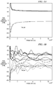
- It is well known that the line impedance, and therefore Z 'L , varies a great deal for different loop topologies, in particular in the presence of bridge-taps. Figures 1a and 1b illustrate the severity of the problem in which real and imaginary parts of the impedance are shown for straight loops (Fig. 1a) and some bridge tap loops (Fig. 1b) respectively.
- It is clear that a single hybrid network cannot achieve the same cancellation levels for all possible loop scenarios. It would therefore be advantageous in view of the foregoing to provide an adaptive hybrid network capable of achieving substantially the same cancellation levels for all possible loop scenarios associated with a particular application.
- The present invention is directed to a method of accomplishing loop classification and the design of hybrid networks for each of the classes. The resulting hybrids are suitable for implementation in a switchable hybrid architecture.
A method according to one embodiment of the invention comprises the steps of dividing a plurality of subscriber loops into a desired number 'C' of classes; determining a target transfer function for each class; and approximating each target transfer function with a linear system capable of being synthesized in hardware.
According to another embodiment, an adaptive passive hybrid system comprises a plurality of passive hybrid networks, each passive hybrid network having a corresponding optimized hybrid transfer function; and a switching element configured to selectively switch each passive hybrid network, such that each passive hybrid network operates to substantially match its corresponding optimized hybrid transfer function with an associated transmit echo transfer function for a desired class of asymmetric digital subscriber loops. - Other aspects and features of the present invention and many of the attendant advantages of the present invention will be readily appreciated as the same become better understood by reference to the following detailed description when considered in connection with the accompanying drawings in which like reference numerals designate like parts throughout the figures thereof and wherein:
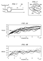
- Figures 1a and 1b are graphs illustrating real and imaginary parts of the impedance for straight loops and some bridge tap loops respectively;
- Figure 2 is a diagram illustrating the general shape of a target minimum hybrid echo cancellation transfer function;
- Figure 3 is a diagram depicting a digital subscriber line "space" and sub-sets of associated loops for which a corresponding hybrid achieves the target minimum hybrid echo rejection transfer function;
- Figures 4a and 4b illustrate echo transfer functions (including first stage HPF) for all loops of interest associated with one exemplary loop classification;
- Figures 5a and 5b illustrate resulting class 1 target transfer functions associated with a plurality of classes when using a 2nd order linear system approximation and passive hybrid transfer functions;
- Figures 6a and 6b illustrate resulting class 2 target transfer functions associated with a plurality of classes when using a 2nd order linear system approximation and passive hybrid transfer functions;
- Figures 7a and 7b illustrate resulting class 3 target transfer functions associated with a plurality of classes when using a 2nd order linear system approximation and passive hybrid transfer functions;
- Figure 8 depicts upstream performance comparisons for all loops associated with a passive hybrid, an adaptive hybrid optimum solution (target hybrid transfer functions) and an adaptive hybrid approximation (2nd order linear system);
- Figure 9 depicts downstream performance comparisons for all loops associated with a passive hybrid, an adaptive hybrid optimum solution (target hybrid transfer functions) and an adaptive hybrid approximation (2nd order linear system);
- Figure 10 shows a pole-zero plot for three 2nd-order hybrids; and
- Figure 11 depicts a receive HPF and an adaptive hybrid topology associated with C passive hybrid networks according to one embodiment of the present invention. While the above-identified drawing figures set forth alternative embodiments, other embodiments of the present invention are also contemplated, as noted in the discussion. In all cases, this disclosure presents illustrated embodiments of the present invention by way of representation and not limitation. Numerous other modifications and embodiments can be devised by those skilled in the art which fall within the scope of the principles of this invention.
-
- In practice, the adaptability of the hybrid network is realized through the selection of a subset of hybrid networks. Selecting among the possible hybrid networks is done based on channel analysis information obtained during modem initialization.
- The hybrid network must operate over the upstream and downstream frequency bands. The hybrid echo cancellation in the upstream (AUS) band is needed to prevent saturation of the receiver. As such, the quantity of interest is the total power attenuation in the upstream band orwith f+US and f-US the maximum and minimum frequencies in the upstream band, respectively. The hybrid echo cancellation in the downstream band (ADS) is needed to further reduce the out-of-band transmit noise. In this case, the figure of merit is the minimum attenuation in the downstream band or
 with f+DS and f-DS the minimum and maximum frequencies in the downstream band, respectively. Since the energy in the upstream band is much larger than the out-of-band noise, the hybrid is designed to provide higher rejection in the upstream band relative to the rejection in the downstream band. The general shape of the hybrid echo cancellation transfer function 100 is depicted in Figure 2.
- The adaptive hybrid solution according to one embodiment requires the design of a number of hybrid networks which result in acceptable performance for all loops belonging to the corresponding class. As such, loops must be classified into classes before the actual hybrid networks can be realized. In Figure 3, a representation according to one embodiment is shown of all possible loops 200 and sub-sets 202, 204, 206 for which the indicated hybrid achieves the hybrid echo rejection targets. Loops that fall within one of these subsets are guaranteed to result in a hybrid echo rejection of at least AUS and ADS in the upstream and downstream bands, respectively. Most preferably, the intersection(s) 208, 210 of these sub-sets will cover most loops of practical interest. The present inventor recognized that the echo cancellation "space" is actually multidimensional; and the problem at hand is therefore one of clustering.
- Classification methodology according to the particular embodiments presented herein are best understood when first noticing that the best hybrid transfer function for a particular loop condition iswhere K is the number of echo transfer functions (loops) considered in the group. If the relative importance of one loop versus another within the group is known, a weighted version of the previous expression can be used, i.e.,
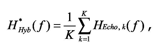

- Thus, the target hybrid transfer function of a particular class is formed as the "center of mass" of the cluster.
- According to one embodiment, classification is done in the following way. Assume first the loops in consideration belong to the set J=(1, ....K} with K the total number of loops, and that we want to divide the loops into C classes. Next, define the hybrid performance goals per class as AUS(1), ..., AUS(C), and ADS(1), ..., ADS(C), for the upstream and downstream frequency regions, respectively. With these definitions and setting J1 = J, we can formwhich represents the hybrid performance for loop 'n' when the echo rejection for loop 'm' is used as the hybrid transfer function.

- A cost function M1 is now defined asThe index 'm1' corresponding to the largest M1 rep resents the loop index with the largest number of "closer" loops. Loop m1 and its K1 closest loops are then assigned to class C1.

The process is then iterated for the next class using the remainder of the loops, i.e.,In general, each iteration uses the loops not previously classified, or with c = (1,..,C); and the (sparse) matrices can then be formed as
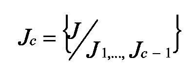 The index 'mc' corresponding to the largest Mc represents the loop index with the largest number of "closer" loops. Loop mc and its Kc closest loops are then assigned to class Cc.
After the classification iteration is completed, the target hybrid function for each class can then be determined as described herein before by calculating the (weighted) average of all echo transfer functions for all loops in the class. - It is possible that certain loops were not properly classified, such that the setis non-empty, the reason being that these loops did not satisfy the performance goals used in the classification stage. In this case, all loops in J C +1 can be assigned to the class that results in the best performance using the corresponding target hybrid transfer function.

- Once the target transfer functions for each class have been found, they must then be approximated with a linear system that can be synthesized in hardware, i.e.,The order of the system is typically constrained by the complexity of the hardware; and it is a design parameter. The numerator and denominator coefficients can be determined by finding a least squares fit of the linear system to the target hybrid transfer function, i.e.,
 The weighting function W(f) can be used to improve the approximation over a particular frequency region, typically, the upstream band.
- The next step is to verify that the hybrid approximation is satisfactory in terms of performance as compared with that for the target hybrid transfer function. Finally, the resulting model is synthesized in an actual hardware implementation.
- Intuitively, the higher the hybrid performance goals the more classes will be needed. Further, the order of the linear model approximations most likely would increase also for certain classes. Thus, when only few hybrid options are available, a lower order approximation might be more appropriate, as it will be able to capture the "average" behavior of the class rather than the detailed characteristics.
- It is also possible to find the least square fit of a transfer function with C real poles and zeros.
- Table 1 shows the test loops considered in one loop classification example. The loop index is used to refer to the particular loop in the plots shown in Figures 4a and 4b.
Test loops. Loop type Loop number Variable Loop index 26 AWG - 3000 1 - 6000 2 - 9000 3 - 12000 4 - 15000 5 CSA 1 - 6 2 - 7 4 - 8 5 - 9 7 - 10 ANSI 2 - 11 5 - 12 6 - 13 9 - 14 12 - 15 13 - 16 - The particular system employed in the loop classification examples discussed herein comprised a Ax5 (TI 5th generation ADSL client-side codec) front-end available from Texas Instruments Incorporated of Dallas, Texas, with a Schott 33818 transformer, two 68 nF coupling capacitors, and a first-stage receive high pass filter (HPF) with a transfer function defined by
Loop classification results. Class Loop Loop index 1 AWG 26 3000 1 AWG 26 6000 2 AWG 26 9000 3 AWG 26 12000 4 AWG 26 15000 5 CSA 1 6 CSA 5 9 ANSI 12 15 CSA 4* 8 ANSI 6* 13 ANSI 13* 16 2 ANSI 2 11 ANSI 5 12 ANSI 9 14 3 CSA 2 7 CSA 7 12 - The upstream and downstream performance comparison 400, 500 between the passive 401, 501, adaptive optimum (target hybrid transfer function) 402, 502 and adaptive approximation (2nd order transfer function) 403, 503 are shown in Figures 8 and 9 respectively. The adaptive hybrid optimum solution 402, 502 outperforms the passive 401, 501 for almost all loops. Similarly, the adaptive hybrid approximation 403, 503 offers gains with respect to the passive solution 401, 501 but not as dramatic as with the optimum hybrid solution 402, 502, yet significant enough to justify its implementation.
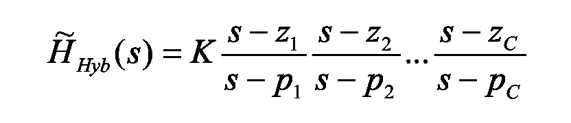
- Examination of the 2nd order approximation for each of the hybrids reveals that they have only real poles and zeros as seen in Figure 10. This result is not surprising since the hybrid has to emulate the first stage HPF which has a zero at DC and a real pole. There is therefore no other alternative for the additional pole and zero but to lie on the real axes as well. This result is significant because it demonstrates that for a second order hybrid, it is not required to implement the hybrid as an active network (arbitrary coefficient second order section). Instead, the hybrid can be implemented with a passive network; and the subtracting operation can be implemented with the same op-amp used for the first stage HPF.
- One appropriate topology 600 is shown in Figure 11. The transfer function of the hybrids 602, 604, 606 is given by
-
-
-
- Using this topology 600, one of C passive hybrid networks can be selected by using switches 608, which may, for example, be integrated into a codec. This approach is depicted in Figure 11.
- Since the circuit topology 600 is differential, two extra pins were found to be required for each additional hybrid option. One embodiment, for example, may include the addition of two hybrid options or 4 pins for a total of 3 possible hybrid networks. This topology was found to offer the greatest flexibility in one embodiment where all the hybrid components are external passive elements (resistors and capacitors).
- In summary explanation, a methodology has been described to accomplish loop classification and the design of hybrid networks for each of the classes. The resulting hybrids have been shown to be suitable for implementation in a switchable hybrid architecture, and implementation examples and estimated performance have been presented herein.
- This invention has been described in considerable detail in order to provide those skilled in the ADSL hybrid art with the information needed to apply the novel principles and to construct and use such specialized components as are required. In view of the foregoing descriptions, it should be apparent that the present invention represents a significant departure from the prior art in construction and operation. However, while particular embodiments of the present invention have been described herein in detail, it is to be understood that various alterations, modifications and substitutions can be made therein without departing from the scope of the present invention, as defined in the claims which follow. For example, while certain embodiments set forth herein illustrate various hardware implementations, the present invention shall be understood to also parallel structures and methods using software implementations as set forth in the claims.
Claims (10)
- A method of implementing a switchable hybrid network for an asymmetric digital subscriber line, the method comprising the steps of:dividing a plurality of subscriber loops into a desired number 'C' of classes;determining a target transfer function for each class; andapproximating each target transfer function with a linear system capable of being synthesized in hardware.
- The method according to claim 1 wherein the step of dividing a plurality of subscriber loops into a desired number of 'C' classes comprises the steps of:defining hybrid performance goals for each desired class;defining a cost function associated with the hybrid performance goals; anddetermining an index corresponding with the largest cost function for each desired class such that a subscriber loop associated with its respective index is assigned to its desired class along with a desired number of closest loops.
- The method according to claim 1 or 2, wherein the step of determining a target transfer function for each class comprises the step of:implementing a linear combination of corresponding echo transfer functions for each loop associated with each class.
- The method according to claim 3 wherein the step of determining a target transfer function for each class further comprises the step of:weighting the linear combination according to relative importance among each loop within each class, such that each target transfer function is formed as the center of mass of the loops associated with each respective class.
- The method according to any one of claims 1 to 4, wherein the step of approximating each target transfer function with a linear system capable of being synthesized in hardware comprises the step of:determining the numerator and denominator coefficients of the linear system in response to a least squares fit of the linear system to the target hybrid transfer function for each class.
- The method according to any one of claims 1 to 5, wherein the step of approximating each target transfer function with a linear system capable of being synthesized in hardware comprises the step of:finding the least squares fit of each target transfer function with 'C' real poles and zeros.
- The method according to any one of claims 1 to 6 further comprising the step of:implementing an adaptive passive hybrid system having 'C' passive hybrid networks and configured to switchably select the 'C' passive hybrid networks into the adaptive passive hybrid system such that loops belonging to each class are constrained to substantially meet performance goals associated with the corresponding class.
- An adaptive passive hybrid system comprising:a plurality of passive hybrid networks, each passive hybrid network having a corresponding optimized hybrid transfer function; anda switching element configured to selectively switch each passive hybrid network, such that each passive hybrid network operates to substantially match its corresponding optimized hybrid transfer function with an associated transmit echo transfer function for a desired class of asymmetric digital subscriber loops.
- The adaptive passive hybrid system according to claim 8, wherein each corresponding optimized hybrid transfer function is defined by desired hybrid performance goals associated with a desired plurality of subscriber loops.
- The adaptive passive hybrid system according to claim 8 or 9 further comprising:a first stage high pass filter configured to filter input signals passing through the plurality of passive hybrid networks.
Applications Claiming Priority (2)
| Application Number | Priority Date | Filing Date | Title |
|---|---|---|---|
| US35469802P | 2002-02-05 | 2002-02-05 | |
| US354698P | 2002-02-05 |
Publications (3)
| Publication Number | Publication Date |
|---|---|
| EP1357731A2 true EP1357731A2 (en) | 2003-10-29 |
| EP1357731A3 EP1357731A3 (en) | 2004-01-28 |
| EP1357731B1 EP1357731B1 (en) | 2014-08-20 |
Family
ID=28791868
Family Applications (1)
| Application Number | Title | Priority Date | Filing Date |
|---|---|---|---|
| EP03100228.0A Expired - Lifetime EP1357731B1 (en) | 2002-02-05 | 2003-02-04 | Switchable hybrid design for asymmetric digital subscriber line |
Country Status (2)
| Country | Link |
|---|---|
| US (1) | US7221754B2 (en) |
| EP (1) | EP1357731B1 (en) |
Citations (3)
| Publication number | Priority date | Publication date | Assignee | Title |
|---|---|---|---|---|
| US5802169A (en) | 1996-04-11 | 1998-09-01 | Intervoice Limited Partnership | System and method for transmission system automatic impedance matching |
| WO2000079693A1 (en) | 1999-06-18 | 2000-12-28 | 2Wire, Inc. | Active hybrid with dynamic impedance matching against different loop conditions and related method |
| US6208732B1 (en) | 1998-02-12 | 2001-03-27 | Globespan Semiconductor, Inc. | Switched hybrid circuit for use with digital subscriber lines |
Family Cites Families (20)
| Publication number | Priority date | Publication date | Assignee | Title |
|---|---|---|---|---|
| JPS6041898B2 (en) * | 1977-12-31 | 1985-09-19 | 株式会社リコー | Transmission/reception circuit |
| US4276450A (en) * | 1979-09-05 | 1981-06-30 | Northern Telecom Limited | Method and apparatus for improving telephone hybrid network |
| EP0234453B1 (en) * | 1986-02-17 | 1991-08-28 | Siemens Aktiengesellschaft | Circuit arrangement for serial data transmission between several stations |
| FR2677831B1 (en) * | 1991-06-17 | 1994-12-09 | Apple Computer | MODEM WITH AN IMPROVED LINE INTERFACE CIRCUIT, ESPECIALLY FOR A COMPUTER. |
| US5416776A (en) * | 1994-05-27 | 1995-05-16 | U.S. Robotics, Inc. | Modem backplane techniques |
| JP3444978B2 (en) * | 1994-07-29 | 2003-09-08 | 富士通株式会社 | IC card type modem and data communication method thereof |
| IL117221A0 (en) * | 1995-02-28 | 1996-06-18 | Gen Instrument Corp | Configurable hybrid medium access control for cable metropolitan area networks |
| US5892910A (en) * | 1995-02-28 | 1999-04-06 | General Instrument Corporation | CATV communication system for changing first protocol syntax processor which processes data of first format to second protocol syntax processor processes data of second format |
| US6385203B2 (en) * | 1996-03-29 | 2002-05-07 | Cisco Technology, Inc. | Communication server apparatus and method |
| US6160843A (en) * | 1996-03-29 | 2000-12-12 | Cisco Technology, Inc. | Communication server apparatus providing XDSL services and method |
| US6101216A (en) * | 1997-10-03 | 2000-08-08 | Rockwell International Corporation | Splitterless digital subscriber line communication system |
| US5999565A (en) * | 1997-10-15 | 1999-12-07 | Cisco Technology, Inc. | Data communication using a modifiable number of XDSL modems |
| US6192109B1 (en) * | 1997-12-24 | 2001-02-20 | Globespan, Inc. | Apparatus and method for improved DSL communication |
| US6163579A (en) * | 1998-03-04 | 2000-12-19 | Analog Devices, Inc. | Broadband modem transformer hybird |
| US6400772B1 (en) * | 1998-06-16 | 2002-06-04 | Rc Networks | Line interface and method for detecting and eliminating an impedance mismatch between a transceiver and a transmission line |
| US5999540A (en) * | 1998-12-22 | 1999-12-07 | Cisco Technology, Inc. | Rate adaptive XDSL communication system and method |
| US6385252B1 (en) * | 1999-05-28 | 2002-05-07 | Lucent Technologies Inc. | High density multiple digital signal connection interface with reduced cross talk |
| CA2277534A1 (en) * | 1999-07-13 | 2001-01-13 | Jim Hjartarson | Combined xdsl and voice line card |
| FR2798022B1 (en) * | 1999-08-30 | 2008-09-26 | St Microelectronics Sa | HYBRID EMISSION-RECEPTION CIRCUIT |
| US7106854B2 (en) * | 2000-01-25 | 2006-09-12 | Sbc Knowledge Ventures, L.P. | XDSL system having selectable hybrid circuitry |
-
2003
- 2003-02-01 US US10/356,787 patent/US7221754B2/en not_active Expired - Lifetime
- 2003-02-04 EP EP03100228.0A patent/EP1357731B1/en not_active Expired - Lifetime
Patent Citations (3)
| Publication number | Priority date | Publication date | Assignee | Title |
|---|---|---|---|---|
| US5802169A (en) | 1996-04-11 | 1998-09-01 | Intervoice Limited Partnership | System and method for transmission system automatic impedance matching |
| US6208732B1 (en) | 1998-02-12 | 2001-03-27 | Globespan Semiconductor, Inc. | Switched hybrid circuit for use with digital subscriber lines |
| WO2000079693A1 (en) | 1999-06-18 | 2000-12-28 | 2Wire, Inc. | Active hybrid with dynamic impedance matching against different loop conditions and related method |
Also Published As
| Publication number | Publication date |
|---|---|
| EP1357731A3 (en) | 2004-01-28 |
| US20030147355A1 (en) | 2003-08-07 |
| EP1357731B1 (en) | 2014-08-20 |
| US7221754B2 (en) | 2007-05-22 |
Similar Documents
| Publication | Publication Date | Title |
|---|---|---|
| US6344773B1 (en) | Flexible monolithic continuous-time analog low-pass filter with minimal circuitry | |
| US6608536B2 (en) | Constant impedance filter | |
| CN109831177A (en) | A kind of more stop-band filters and its implementation | |
| CN109690946A (en) | Acoustic wave filter device, multiplexer, high-frequency front-end circuit and communication device | |
| US9312912B2 (en) | Signal transmitting and receiving circuit of digital subscriber line | |
| US6147558A (en) | Attenuating volume control | |
| US7386119B1 (en) | Filtered transmit cancellation in a full-duplex modem data access arrangement (DAA) | |
| US5703903A (en) | Method and apparatus for adaptive filtering in a high interference environment | |
| US6031432A (en) | Balancing apparatus for signal transmissions | |
| CN1263230C (en) | Circuit arrangement for the suppression of analogue echoes | |
| EP1391055B1 (en) | Line interface with a matching impedance coupled to a feedback path | |
| US7010025B1 (en) | Circuit and method for an improved front end in duplex signal communication systems | |
| CN115668781A (en) | Front-end circuitry for data receivers and related systems, methods and apparatus | |
| EP1357731A2 (en) | Switchable hybrid design for asymmetric digital subscriber line | |
| US4185250A (en) | Voice frequency RC active filter | |
| US6608898B1 (en) | Band pass and notch filters for echo reduction with less phase distortion | |
| US20020121930A1 (en) | Combined active impedance and filter in line drivers | |
| US6404278B2 (en) | Separation of plural band pass filters | |
| US6754288B2 (en) | Line receiver with improved dynamic range | |
| US12456963B2 (en) | Bandpass filter having an additional shunt resonator circuit | |
| JP2002335193A (en) | Two line/four line conversion circuit | |
| Atsuwe et al. | OPTIMIZED EIGHTH-ORDER ACTIVE-R BANDPASS FILTER FOR UHF RFID SYSTEMS: DESIGN, SIMULATION, AND EXPERIMENTAL VALIDATION | |
| Laker et al. | Design of minimum sensitivity multiple loop feedback bandpass active filters | |
| US10243530B1 (en) | Stepped attenuation circuit with constant decibel steps | |
| US20040061569A1 (en) | ADSL customer premises subscriber loop equalizer |
Legal Events
| Date | Code | Title | Description |
|---|---|---|---|
| PUAI | Public reference made under article 153(3) epc to a published international application that has entered the european phase |
Free format text: ORIGINAL CODE: 0009012 |
|
| AK | Designated contracting states |
Kind code of ref document: A2 Designated state(s): AT BE BG CH CY CZ DE DK EE ES FI FR GB GR HU IE IT LI LU MC NL PT SE SI SK TR |
|
| AX | Request for extension of the european patent |
Extension state: AL LT LV MK RO |
|
| PUAL | Search report despatched |
Free format text: ORIGINAL CODE: 0009013 |
|
| AK | Designated contracting states |
Kind code of ref document: A3 Designated state(s): AT BE BG CH CY CZ DE DK EE ES FI FR GB GR HU IE IT LI LU MC NL PT SE SI SK TR |
|
| AX | Request for extension of the european patent |
Extension state: AL LT LV MK RO |
|
| RIC1 | Information provided on ipc code assigned before grant |
Ipc: 7H 04B 3/20 B Ipc: 7H 04B 1/58 A Ipc: 7H 04M 11/06 B Ipc: 7H 03H 7/38 B |
|
| 17P | Request for examination filed |
Effective date: 20040728 |
|
| 17Q | First examination report despatched |
Effective date: 20040825 |
|
| AKX | Designation fees paid |
Designated state(s): DE FR GB |
|
| 17Q | First examination report despatched |
Effective date: 20040825 |
|
| GRAP | Despatch of communication of intention to grant a patent |
Free format text: ORIGINAL CODE: EPIDOSNIGR1 |
|
| INTG | Intention to grant announced |
Effective date: 20140228 |
|
| GRAS | Grant fee paid |
Free format text: ORIGINAL CODE: EPIDOSNIGR3 |
|
| GRAA | (expected) grant |
Free format text: ORIGINAL CODE: 0009210 |
|
| AK | Designated contracting states |
Kind code of ref document: B1 Designated state(s): DE FR GB |
|
| REG | Reference to a national code |
Ref country code: GB Ref legal event code: FG4D |
|
| REG | Reference to a national code |
Ref country code: DE Ref legal event code: R096 Ref document number: 60346649 Country of ref document: DE Effective date: 20141002 |
|
| REG | Reference to a national code |
Ref country code: DE Ref legal event code: R097 Ref document number: 60346649 Country of ref document: DE |
|
| PLBE | No opposition filed within time limit |
Free format text: ORIGINAL CODE: 0009261 |
|
| STAA | Information on the status of an ep patent application or granted ep patent |
Free format text: STATUS: NO OPPOSITION FILED WITHIN TIME LIMIT |
|
| 26N | No opposition filed |
Effective date: 20150521 |
|
| REG | Reference to a national code |
Ref country code: FR Ref legal event code: PLFP Year of fee payment: 14 |
|
| REG | Reference to a national code |
Ref country code: FR Ref legal event code: PLFP Year of fee payment: 15 |
|
| REG | Reference to a national code |
Ref country code: FR Ref legal event code: PLFP Year of fee payment: 16 |
|
| PGFP | Annual fee paid to national office [announced via postgrant information from national office to epo] |
Ref country code: DE Payment date: 20180207 Year of fee payment: 16 Ref country code: GB Payment date: 20180125 Year of fee payment: 16 |
|
| PGFP | Annual fee paid to national office [announced via postgrant information from national office to epo] |
Ref country code: FR Payment date: 20180118 Year of fee payment: 16 |
|
| REG | Reference to a national code |
Ref country code: DE Ref legal event code: R119 Ref document number: 60346649 Country of ref document: DE |
|
| GBPC | Gb: european patent ceased through non-payment of renewal fee |
Effective date: 20190204 |
|
| PG25 | Lapsed in a contracting state [announced via postgrant information from national office to epo] |
Ref country code: DE Free format text: LAPSE BECAUSE OF NON-PAYMENT OF DUE FEES Effective date: 20190903 Ref country code: GB Free format text: LAPSE BECAUSE OF NON-PAYMENT OF DUE FEES Effective date: 20190204 |
|
| PG25 | Lapsed in a contracting state [announced via postgrant information from national office to epo] |
Ref country code: FR Free format text: LAPSE BECAUSE OF NON-PAYMENT OF DUE FEES Effective date: 20190228 |