EP1357646A2 - Spiral cable device - Google Patents
Spiral cable device Download PDFInfo
- Publication number
- EP1357646A2 EP1357646A2 EP03009319A EP03009319A EP1357646A2 EP 1357646 A2 EP1357646 A2 EP 1357646A2 EP 03009319 A EP03009319 A EP 03009319A EP 03009319 A EP03009319 A EP 03009319A EP 1357646 A2 EP1357646 A2 EP 1357646A2
- Authority
- EP
- European Patent Office
- Prior art keywords
- cylindrical casing
- flexible flat
- leads
- flat cable
- inner cylinder
- Prior art date
- Legal status (The legal status is an assumption and is not a legal conclusion. Google has not performed a legal analysis and makes no representation as to the accuracy of the status listed.)
- Granted
Links
Images




Classifications
-
- B—PERFORMING OPERATIONS; TRANSPORTING
- B60—VEHICLES IN GENERAL
- B60R—VEHICLES, VEHICLE FITTINGS, OR VEHICLE PARTS, NOT OTHERWISE PROVIDED FOR
- B60R16/00—Electric or fluid circuits specially adapted for vehicles and not otherwise provided for; Arrangement of elements of electric or fluid circuits specially adapted for vehicles and not otherwise provided for
- B60R16/02—Electric or fluid circuits specially adapted for vehicles and not otherwise provided for; Arrangement of elements of electric or fluid circuits specially adapted for vehicles and not otherwise provided for electric constitutive elements
- B60R16/023—Electric or fluid circuits specially adapted for vehicles and not otherwise provided for; Arrangement of elements of electric or fluid circuits specially adapted for vehicles and not otherwise provided for electric constitutive elements for transmission of signals between vehicle parts or subsystems
- B60R16/027—Electric or fluid circuits specially adapted for vehicles and not otherwise provided for; Arrangement of elements of electric or fluid circuits specially adapted for vehicles and not otherwise provided for electric constitutive elements for transmission of signals between vehicle parts or subsystems between relatively movable parts of the vehicle, e.g. between steering wheel and column
-
- H—ELECTRICITY
- H01—ELECTRIC ELEMENTS
- H01R—ELECTRICALLY-CONDUCTIVE CONNECTIONS; STRUCTURAL ASSOCIATIONS OF A PLURALITY OF MUTUALLY-INSULATED ELECTRICAL CONNECTING ELEMENTS; COUPLING DEVICES; CURRENT COLLECTORS
- H01R35/00—Flexible or turnable line connectors, i.e. the rotation angle being limited
- H01R35/02—Flexible line connectors without frictional contact members
- H01R35/025—Flexible line connectors without frictional contact members having a flexible conductor wound around a rotation axis
Definitions
- the present invention relates to a spiral cable device, which is suitable for use in, for example, a variable gear ratio steering device of vehicles.
- Japanese unexamined, published patent application No, 10-164745 (1998-164745) discloses a prior art spiral cable device.
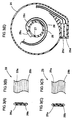
- the cable device is provided with a cylindrical casing 90, an inner cylinder 91 rotatable relative to the cylindrical casing 90 within the same, and a flexible flat cable 92 connected to the inner cylinder 91 at one end thereof and to the cylindrical casing 90 at the other end thereof to be wound around the Inner cylinder 91.
- the flexible flat cable 92 Is composed of plural leads 92a which are coated with flexible resin 92b to be isolated electrically.
- the spiral cable device is employed to electrically connect the members which are relatively rotatable with each other in a variable gear ration steering device, an air bag device or the like of vehicles.
- the spiral cable device is used in, for example, a variable gear ratio steering device of a vehicle
- the cylindrical housing 90 is fixed to a vehicle body
- the inner cylinder 91 is fixed to a housing of the variable gear ratio steering device.
- one end of the flexible flat cable 92 is connected to the inner cylinder 91 by means of a terminal 93, and leads extending from the inner cylinder 91 are connected to a stator of a motor or the like.
- the other end of the flexible flat cable 92 is connected to the cylindrical casing 90 by means of a terminal 94, and leads extending from the cylinder casing 90 are connected to a battery and an ECU (Electronic Control Unit) of the vehicle.
- ECU Electronic Control Unit
- the spiral cable device when the cylindrical casing 90 and the inner cylinder 91 are rotated relative to each other, the battery and the ECU are maintained connected electrically with the stator of the motor as long as the angle of the relative rotation therebetween is within the winding range of the flexible flat cable 92.
- the flexible flat cable 92 arranges the plural leads 92a within a single layer and is wound to form only a single layer of the leads 92a in the radial direction of the winding.
- the flexible flat cable 92 is of the type that the plural leads 92a are coated to be isolated electrically
- the flexible flat cable is caused to be large in width so that the cylindrical casing 90 containing the flat cable 92 and the inner cylinder 91 are enlarged in the axial direction thereof.
- This disadvantageously causes the axial length of the spiral cable device to be enlarged. Therefore, when the spiral cable device were employed in the aforementioned variable gear ratio steering device, air bag device or the like of the vehicle, the axial length of the same would be enlarged thereby affecting the capability of being mounted on vehicles or the like.
- a spiral cable device having a cylindrical casing, an inner cylinder provided to be rotatable relative to the cylindrical casing within the same, and a flexible flat cable connected to the inner cylinder at one end thereof and to the cylindrical casing at the other end thereof and having plural leads coated to be isolated electrically, wherein the flexible flat cable has the leads arranged in a single layer, and wherein plural flexible flat cables each having the configuration as that defined above are placed to form multiple layers of the leads in the radial direction of the cylindrical casing.
- each of the flexible flat cables has a single layer of the leads and Is overlapped with one another in the radial direction. This allows the number of the leads to be decreased per flexible flat cable. Therefore, even where the flat cable Is to have many leads, the width of the flat cable can be made small, whereby the cylinder casing and hence, the spiral cable device can be diminished in length in the axial direction.
- the flexible flat cable has the leads arranged in a single layer and is folded to form multiple layers of the leads in the radial direction of the cylindrical casing.
- the flexible flat cable is folded to form multiple layers of the leads in the radial direction. This makes small the width which the flexible flat cable occupies within the cylindrical casing in the axial direction of the same. Consequently, the cylindrical casing and hence, the spiral cable device can be made small in the axial direction.
- the flexible flat cable has the leads arranged in multiple layers in the radial direction of the cylindrical casing.
- the number of the leads which are to be arranged in each layer in the axial direction of the spiral cable device can be reduced, whereby the width of the flexible flat cable can be made small. Consequently, the cylindrical casing and hence, the spiral cable device can be made small in the axial direction.
- a spiral cable device in the first embodiment embodies the first invention and is employed in a variable gear ratio steering device 1 of a steering system shown in Figure 1.
- the steering system includes a steering wheel or handle 70 which is connected to the upper end of an upper steering shaft 71 constituting an input shaft, through a constant velocity joint (not shown).
- the lower end of the upper steering shaft 71 is connected to the upper end of a lower steering shaft 72 constituting an output shaft, through the variable gear ratio steering device 1.
- the lower end of the lower steering shaft 72 is provided through another constant velocity joint (not shown) with a pinion (not shown), which is in meshing engagement with a rack shaft 74 within a steering gear box 73.
- Opposite ends of the rack shaft 74 are connected to respective one ends of tie rods, whose other ends are connected to steered road wheels 77 through knuckle arms 76, respectively.
- the upper steering shaft 71 is provided thereon with a steering angle sensor 78 for detecting the steering angle of the steering handle 70
- the lower steering shaft 72 is provided thereon with a steered angle sensor 79 for detecting the steered angle of the steered road wheels 77.
- the steering angle of the steering handle 70 and the steered angle of the steered road wheels 77 which angles are detected respectively by the steering angle sensor 78 and the steered angle sensor 79 are input into an ECU (Electronic Control Unit) 80, to which there Is also input a vehicle speed from a vehicle speed sensor 81 for detecting the vehicle speed.
- the ECU 80 outputs a control signal to the variable gear ratio steering device 1 for controlling the same.
- FIG. 2 shows the detail of the variable gear ratio steering device 1 in an enlarged scale.
- the device 1 is provided with a lock mechanism 3, a motor 4 and a strain wave gearing mechanism 5 as a gear mechanism within housings 6-8 connected bodily.
- the device 1 is also provided with a spiral cable device 2 outside the housing 6. And, the lower end 71a of the upper steering shaft 71 and the upper end 72a of the lower steering shaft 72 are connected by the variable gear ratio steering device 1.
- An insertion portion 6a is formed at a portion closer to the upper steering shaft 71 of the housing 6.
- the lower end 71a of the upper steering shaft 71 is inserted together with a leaf spring 6b into the insertion portion 6a, so that the housing 6 and the upper steering shaft 71 are secured to be rotatable bodily.
- the spiral cable device 2 is provided with a cylindrical casing 26 made of resin which is supported on a vehicle body (not shown) and an inner cylinder 27 made of resin which is provided to be rotatable relative to the cylindrical casing 26 within the same and which is secured to the external surface of the insertion portion 6a.
- a first flexible flat cable 28 and a second flexible flat cable 29 are interposed between the cylindrical casing 26 and the inner cylinder 27 and are wound around the inner cylinder 27 to be arranged double in the radial direction of the casing 26, the cylinder 27 and the like.
- the first flexible flat cable 28 is composed of plural leads 28a which are arranged in a single layer and which are coated to be electrically isolated by means of a flexible PET (Polyethylene Terephthalate) film 28b.
- the second flexible flat cable 29 is composed of plural leads 29a which are arranged in a single layer and which are coated to be electrically isolated by means of a flexible PET film 29b.
- the flexible flat cable 28 is provided for supplying the motor 4 and a drive device of the lock mechanism 3 with electric power, while the flexible flat cable 29 is provided for transmitting control signals output from the ECU 80 to the motor and the like.
- These flexible flat cables 28, 29 are connected at respective one ends thereof to the inner cylinder 27 by means of terminals 28c, 29c and at respective other ends thereof to the cylindrical casing 26 by means of terminals 28d, 29d.
- each of the leads 30 extending from the inner cylinder 27 is connected to a bus bar 12a led out from the stator 12 or the like of the motor 4 by being welded to the bus bar 12a.
- each of the leads (not shown) extending from the cylindrical casing 26 is connected to a battery (not shown) and the ECU 80 ( Figure 1) through respective connectors.
- the motor 4 has a motor housing 10 secured within the housing 7.
- the motor housing 10 is composed of a motor housing body 10a and a motor end plate 10b.
- the motor housing body 10a takes the form of a cup having a shaft hole 10c at the center thereof and is secured to the housing 7.
- the motor end plate 10b is secured to close an opening portion of the motor housing 10a.
- the stator 12 is fixed to the internal surface of the motor housing body 10a.
- a rotor 14 is provided within the stator 12 to be rotated by the same.
- the rotor 14 is fixed over a motor shaft 13, which axially extends from the opposite ends of the rotor 14.
- One end of the motor shaft 13 close to the spiral cable device 2 is able to be locked by the lock mechanism 3 onto the housings 6-8.
- the other end 13b of the motor shaft 13 is connected to the strain wave gearing mechanism 5.
- the flexible flat cables 28, 29 are radially doubled to form multiple layers of leads 28a, 29a, and the number of the leads 28a or 29a per cable 28 or 29 is chosen to three (3) or four (4).
- the spiral cable device 2 of the embodiment is capable of having the widths of the flat cables 28, 29 reduced to almost the half and therefore, of making the cylindrical casing 26 and the inner cylinder 27 diminished in the axial direction thereof. Accordingly, the spiral cable device 2 of the embodiment can be short in the axial length, whereby the capability of the device being mounted on vehicles can be improved.
- a spiral cable device in the second embodiment embodies the second invention.
- a flexible flat cable 30 wherein plural leads 30a are arranged in a single layer and are coated to be isolated electrically by means of a PET film 30b having flexibility, and the flexible flat cable 30 is folded to be radially doubled within the cylindrical casing 26. That is, the cable 30 is folded to form multiple layers of the leads 30a.
- Other configurations of the second embodiment are the same to those in the first embodiment.
- the flexible flat cable 30 is folded to be radially doubled, i.e., to form multiple layers of the leads 30a.
- Other functions and effects of the second embodiment are the same to those of the first embodiment.
- a spiral cable device in the third embodiment embodies the third invention.
- a flexible flat cable 31 wherein plural leads 31a are arranged in two layers and are coated to be isolated electrically by means of a PET film 31b having flexibility.
- Other configurations of the second embodiment are the same to those in the first embodiment.
- the flexible flat cable 31 has the plural leads 31a arranged in the two layers in the radial direction, the number of the leads which are arranged in each layer in the axial direction of the spiral cable device 2 can be reduced to the half compared with that in the prior art device wherein all the leads are arranged in a single layer, whereby the width of the flexible flat cable 31 can be made small. Consequently, the cylindrical casing 26 can be made small in the axial direction, and thus, the cable device 2 and the device (e.g., the variable gear ratio steering device 1) incorporating the same can also be made small in the axial direction thereof, Other functions and effects of the third embodiment are the same to those of the first embodiment.
- the axial length of the spiral cable device can be made short even where the flexible flat cable has plural leads. Accordingly, where the spiral cable device is employed in, for example, a variable gear ratio steering device, an air bag device or the like, an excellent capability can be realized in mounting any of these devices on a vehicle.
Landscapes
- Engineering & Computer Science (AREA)
- Mechanical Engineering (AREA)
- Power Steering Mechanism (AREA)
- Steering Controls (AREA)
- Storing, Repeated Paying-Out, And Re-Storing Of Elongated Articles (AREA)
- Electric Cable Arrangement Between Relatively Moving Parts (AREA)
- Flexible Shafts (AREA)
Abstract
Description
Claims (3)
- A spiral cable device having a cylindrical casing, an inner cylinder provided to be rotatable relative to the cylindrical casing within the same, and a flexible flat cable connected to the inner cylinder at one end thereof for being wound around the same and to the cylindrical casing at the other end thereof and having plural leads coated to be isolated electrically, wherein:the flexible flat cable has the leads arranged in a single layer, and plural flexible flat cables each having the same configuration as that defined above are placed to form multiple layers of the leads in the radial direction of the cylindrical casing.
- A spiral cable device having a cylindrical casing, an inner cylinder provided to be rotatable relative to the cylindrical casing within the same, and a flexible flat cable connected to the inner cylinder at one end thereof for being wound around the same and to the cylindrical casing at the other end thereof and having plural leads coated to be isolated electrically, wherein:the flexible flat cable has the leads arranged in a single layer and is folded to form multiple layers of the leads in the radial direction of the cylindrical casing.
- A spiral cable device having a cylindrical casing, an inner cylinder provided to be rotatable relative to the cylindrical casing within the same, and a flexible flat cable connected to the inner cylinder at one end thereof for being wound around the same and to the cylindrical casing at the other end thereof and having plural leads coated to be isolated electrically, wherein:the flexible flat cable has the leads arranged in multiple layers in the radial direction of the cylindrical casing.
Applications Claiming Priority (2)
| Application Number | Priority Date | Filing Date | Title |
|---|---|---|---|
| JP2002126546 | 2002-04-26 | ||
| JP2002126546A JP2003324835A (en) | 2002-04-26 | 2002-04-26 | Spiral cable device |
Publications (3)
| Publication Number | Publication Date |
|---|---|
| EP1357646A2 true EP1357646A2 (en) | 2003-10-29 |
| EP1357646A3 EP1357646A3 (en) | 2005-01-19 |
| EP1357646B1 EP1357646B1 (en) | 2013-07-31 |
Family
ID=28786828
Family Applications (1)
| Application Number | Title | Priority Date | Filing Date |
|---|---|---|---|
| EP03009319.9A Expired - Lifetime EP1357646B1 (en) | 2002-04-26 | 2003-04-24 | Spiral cable device |
Country Status (3)
| Country | Link |
|---|---|
| US (1) | US7038139B2 (en) |
| EP (1) | EP1357646B1 (en) |
| JP (1) | JP2003324835A (en) |
Cited By (2)
| Publication number | Priority date | Publication date | Assignee | Title |
|---|---|---|---|---|
| DE102007020386A1 (en) * | 2007-03-21 | 2008-09-25 | Tyco Electronics Amp Gmbh | Rotor and stator arrangement for measuring e.g. rotation angle, of shaft, has electrical line guided from one connector of rotor to another connector of rotor by coil around axis of rotation of rotor |
| CN114242309A (en) * | 2021-12-20 | 2022-03-25 | 中科(湖南)先进轨道交通研究院有限公司 | Construction method of anti-bending cable for railway |
Families Citing this family (4)
| Publication number | Priority date | Publication date | Assignee | Title |
|---|---|---|---|---|
| JP4008402B2 (en) * | 2003-09-30 | 2007-11-14 | 日本圧着端子製造株式会社 | Anisotropic conductive sheet cable and manufacturing method thereof |
| JP5195778B2 (en) | 2009-03-17 | 2013-05-15 | 株式会社デンソーウェーブ | Wiring device for robot rotary joint |
| JP5402748B2 (en) * | 2010-03-18 | 2014-01-29 | 株式会社デンソーウェーブ | Wiring device for rotary joint of industrial robot |
| JP6511939B2 (en) * | 2015-04-27 | 2019-05-15 | セイコーエプソン株式会社 | robot |
Family Cites Families (23)
| Publication number | Priority date | Publication date | Assignee | Title |
|---|---|---|---|---|
| US3300572A (en) * | 1963-12-18 | 1967-01-24 | Sanders Associates Inc | Extensible and retractable flexible circuit cable |
| US3818122A (en) * | 1973-05-29 | 1974-06-18 | Schjeldahl Co G T | Flexible printed circuit interconnecting cable |
| US4808773A (en) * | 1987-10-01 | 1989-02-28 | Digital Equipment Corporation | Low impedance cable |
| US5057646A (en) * | 1990-03-21 | 1991-10-15 | Smartouse Limited Partnership | Folded ribbon cable assembly having integral shielding |
| JP2575481Y2 (en) * | 1991-08-21 | 1998-06-25 | 古河電気工業株式会社 | Fixing structure of flat cable connection part in rotary connector |
| JP2550413Y2 (en) * | 1991-11-26 | 1997-10-15 | 古河電気工業株式会社 | Rotating connector |
| JP3050688B2 (en) * | 1992-02-20 | 2000-06-12 | 古河電気工業株式会社 | Transmission device between rotating body and fixed body |
| US5342991A (en) * | 1993-03-03 | 1994-08-30 | The Whitaker Corporation | Flexible hybrid branch cable |
| US5428187A (en) * | 1994-02-24 | 1995-06-27 | Molex Incorporated | Shielded hybrid ribbon cable assembly |
| CA2145608C (en) * | 1994-03-29 | 2000-06-20 | Kazuya Akashi | Wire harness and method of manufacturing the same |
| JPH10164745A (en) | 1996-11-25 | 1998-06-19 | Toyota Motor Corp | Spiral cable device |
| JP3408949B2 (en) * | 1997-06-09 | 2003-05-19 | アルプス電気株式会社 | Rotating connector |
| JP2000278827A (en) * | 1999-03-26 | 2000-10-06 | Nissin Electric Co Ltd | Metal-enclosed switchgear |
| USH1991H1 (en) | 1999-07-01 | 2001-09-04 | Methode Electronics, Inc. | Clockspring using flexible printed wiring |
| JP3693859B2 (en) * | 1999-07-15 | 2005-09-14 | ナイルス株式会社 | Rotating connector device |
| JP2001076802A (en) * | 1999-09-03 | 2001-03-23 | Auto Network Gijutsu Kenkyusho:Kk | Rotary connection device |
| JP2001135156A (en) | 1999-11-05 | 2001-05-18 | Yazaki Corp | Flat cable |
| US6730622B2 (en) * | 1999-12-21 | 2004-05-04 | The Procter & Gamble Company | Electrical cable |
| JP4716541B2 (en) | 2000-04-14 | 2011-07-06 | ナイルス株式会社 | Rotating connector device |
| JP2001341945A (en) | 2000-05-30 | 2001-12-11 | Sumitomo Wiring Syst Ltd | Cable reel |
| JP2002034139A (en) * | 2000-07-17 | 2002-01-31 | Auto Network Gijutsu Kenkyusho:Kk | Rotary connection device |
| CA2319956A1 (en) * | 2000-09-18 | 2002-03-18 | John Mccrindle | Temporary use bowling shoe |
| DE20104321U1 (en) * | 2001-03-07 | 2001-05-31 | Petri Ag, 63743 Aschaffenburg | Device for transmitting electrical signals between two mutually rotatable assemblies of a steering device for motor vehicles |
-
2002
- 2002-04-26 JP JP2002126546A patent/JP2003324835A/en active Pending
-
2003
- 2003-04-23 US US10/420,841 patent/US7038139B2/en not_active Expired - Lifetime
- 2003-04-24 EP EP03009319.9A patent/EP1357646B1/en not_active Expired - Lifetime
Cited By (4)
| Publication number | Priority date | Publication date | Assignee | Title |
|---|---|---|---|---|
| DE102007020386A1 (en) * | 2007-03-21 | 2008-09-25 | Tyco Electronics Amp Gmbh | Rotor and stator arrangement for measuring e.g. rotation angle, of shaft, has electrical line guided from one connector of rotor to another connector of rotor by coil around axis of rotation of rotor |
| DE102007020386B4 (en) * | 2007-03-21 | 2009-04-16 | Tyco Electronics Amp Gmbh | Arrangement with a rotor and a stator with line connection |
| CN114242309A (en) * | 2021-12-20 | 2022-03-25 | 中科(湖南)先进轨道交通研究院有限公司 | Construction method of anti-bending cable for railway |
| CN114242309B (en) * | 2021-12-20 | 2024-01-09 | 中科(湖南)先进轨道交通研究院有限公司 | Construction method of bending-resistant cable for railway |
Also Published As
| Publication number | Publication date |
|---|---|
| EP1357646B1 (en) | 2013-07-31 |
| US20030221862A1 (en) | 2003-12-04 |
| US7038139B2 (en) | 2006-05-02 |
| EP1357646A3 (en) | 2005-01-19 |
| JP2003324835A (en) | 2003-11-14 |
Similar Documents
| Publication | Publication Date | Title |
|---|---|---|
| US7290638B2 (en) | Electric power steering system | |
| US4604912A (en) | Steering wheel | |
| US20150372466A1 (en) | Waterproof structure for electronic unit | |
| US5890921A (en) | Rotary connector | |
| US12552445B2 (en) | Electric power steering apparatus | |
| KR20200144973A (en) | Steer-by-wire type steering apparatus | |
| US20260116459A1 (en) | Steer-by-wire steering apparatus | |
| JP2576602Y2 (en) | Brushless electric signal device for automobile | |
| JP2004058785A (en) | Vehicle steering control device | |
| US7038139B2 (en) | Spiral cable device | |
| JP5311103B2 (en) | Vehicle steering system | |
| JP3818801B2 (en) | Electric steering device | |
| US7475755B2 (en) | Electric power steering device | |
| CN115720426A (en) | drive unit with control unit | |
| JP2004314901A (en) | Rotary connector with rotation sensor | |
| US12497093B2 (en) | Steer by wire type steering apparatus | |
| JP7854057B2 (en) | Electric drive system and electric power steering system | |
| JP2003324836A (en) | Spiral cable device | |
| JP2010132039A (en) | Vehicular steering device | |
| CN116457266A (en) | Electronic control device and wiring method of ground wire | |
| JP4235892B2 (en) | Electric power steering device | |
| JP2023110139A (en) | steering gear | |
| CN113471730B (en) | Power pack with flexible electrical connector locations | |
| US12522278B2 (en) | Steer by wire type steering apparatus | |
| CN220904707U (en) | Power drive assembly, chassis and vehicle |
Legal Events
| Date | Code | Title | Description |
|---|---|---|---|
| PUAI | Public reference made under article 153(3) epc to a published international application that has entered the european phase |
Free format text: ORIGINAL CODE: 0009012 |
|
| AK | Designated contracting states |
Kind code of ref document: A2 Designated state(s): AT BE BG CH CY CZ DE DK EE ES FI FR GB GR HU IE IT LI LU MC NL PT RO SE SI SK TR |
|
| AX | Request for extension of the european patent |
Extension state: AL LT LV MK |
|
| PUAL | Search report despatched |
Free format text: ORIGINAL CODE: 0009013 |
|
| AK | Designated contracting states |
Kind code of ref document: A3 Designated state(s): AT BE BG CH CY CZ DE DK EE ES FI FR GB GR HU IE IT LI LU MC NL PT RO SE SI SK TR |
|
| AX | Request for extension of the european patent |
Extension state: AL LT LV MK |
|
| 17P | Request for examination filed |
Effective date: 20050718 |
|
| AKX | Designation fees paid |
Designated state(s): DE FR GB |
|
| RAP1 | Party data changed (applicant data changed or rights of an application transferred) |
Owner name: JTEKT CORPORATION Owner name: FURUKAWA ELECTRIC CO., LTD. |
|
| RIN1 | Information on inventor provided before grant (corrected) |
Inventor name: MATSUDA, MORIHIRO Inventor name: KANAYAMA, YUKIHIKO Inventor name: KAWAMURO, JUNJI Inventor name: SHONO, SHOICHI Inventor name: OKADA, YASUNORI |
|
| 17Q | First examination report despatched |
Effective date: 20051216 |
|
| GRAP | Despatch of communication of intention to grant a patent |
Free format text: ORIGINAL CODE: EPIDOSNIGR1 |
|
| GRAS | Grant fee paid |
Free format text: ORIGINAL CODE: EPIDOSNIGR3 |
|
| GRAA | (expected) grant |
Free format text: ORIGINAL CODE: 0009210 |
|
| AK | Designated contracting states |
Kind code of ref document: B1 Designated state(s): DE FR GB |
|
| REG | Reference to a national code |
Ref country code: GB Ref legal event code: FG4D |
|
| REG | Reference to a national code |
Ref country code: DE Ref legal event code: R096 Ref document number: 60344597 Country of ref document: DE Effective date: 20130926 |
|
| PLBE | No opposition filed within time limit |
Free format text: ORIGINAL CODE: 0009261 |
|
| STAA | Information on the status of an ep patent application or granted ep patent |
Free format text: STATUS: NO OPPOSITION FILED WITHIN TIME LIMIT |
|
| 26N | No opposition filed |
Effective date: 20140502 |
|
| REG | Reference to a national code |
Ref country code: DE Ref legal event code: R097 Ref document number: 60344597 Country of ref document: DE Effective date: 20140502 |
|
| REG | Reference to a national code |
Ref country code: FR Ref legal event code: PLFP Year of fee payment: 14 |
|
| REG | Reference to a national code |
Ref country code: FR Ref legal event code: PLFP Year of fee payment: 15 |
|
| REG | Reference to a national code |
Ref country code: FR Ref legal event code: PLFP Year of fee payment: 16 |
|
| PGFP | Annual fee paid to national office [announced via postgrant information from national office to epo] |
Ref country code: GB Payment date: 20220303 Year of fee payment: 20 |
|
| PGFP | Annual fee paid to national office [announced via postgrant information from national office to epo] |
Ref country code: FR Payment date: 20220308 Year of fee payment: 20 |
|
| PGFP | Annual fee paid to national office [announced via postgrant information from national office to epo] |
Ref country code: DE Payment date: 20220302 Year of fee payment: 20 |
|
| REG | Reference to a national code |
Ref country code: DE Ref legal event code: R071 Ref document number: 60344597 Country of ref document: DE |
|
| REG | Reference to a national code |
Ref country code: GB Ref legal event code: PE20 Expiry date: 20230423 |
|
| PG25 | Lapsed in a contracting state [announced via postgrant information from national office to epo] |
Ref country code: GB Free format text: LAPSE BECAUSE OF EXPIRATION OF PROTECTION Effective date: 20230423 |