EP1357617A1 - Gas diffusion electrode and fuel cell using this - Google Patents
Gas diffusion electrode and fuel cell using this Download PDFInfo
- Publication number
- EP1357617A1 EP1357617A1 EP02702748A EP02702748A EP1357617A1 EP 1357617 A1 EP1357617 A1 EP 1357617A1 EP 02702748 A EP02702748 A EP 02702748A EP 02702748 A EP02702748 A EP 02702748A EP 1357617 A1 EP1357617 A1 EP 1357617A1
- Authority
- EP
- European Patent Office
- Prior art keywords
- gas diffusion
- diffusion electrode
- gas
- layer
- polymer electrolyte
- Prior art date
- Legal status (The legal status is an assumption and is not a legal conclusion. Google has not performed a legal analysis and makes no representation as to the accuracy of the status listed.)
- Withdrawn
Links
Images



Classifications
-
- H—ELECTRICITY
- H01—ELECTRIC ELEMENTS
- H01M—PROCESSES OR MEANS, e.g. BATTERIES, FOR THE DIRECT CONVERSION OF CHEMICAL ENERGY INTO ELECTRICAL ENERGY
- H01M4/00—Electrodes
- H01M4/86—Inert electrodes with catalytic activity, e.g. for fuel cells
-
- H—ELECTRICITY
- H01—ELECTRIC ELEMENTS
- H01M—PROCESSES OR MEANS, e.g. BATTERIES, FOR THE DIRECT CONVERSION OF CHEMICAL ENERGY INTO ELECTRICAL ENERGY
- H01M4/00—Electrodes
- H01M4/86—Inert electrodes with catalytic activity, e.g. for fuel cells
- H01M4/88—Processes of manufacture
- H01M4/8825—Methods for deposition of the catalytic active composition
- H01M4/8828—Coating with slurry or ink
-
- H—ELECTRICITY
- H01—ELECTRIC ELEMENTS
- H01M—PROCESSES OR MEANS, e.g. BATTERIES, FOR THE DIRECT CONVERSION OF CHEMICAL ENERGY INTO ELECTRICAL ENERGY
- H01M4/00—Electrodes
- H01M4/86—Inert electrodes with catalytic activity, e.g. for fuel cells
- H01M4/8605—Porous electrodes
-
- H—ELECTRICITY
- H01—ELECTRIC ELEMENTS
- H01M—PROCESSES OR MEANS, e.g. BATTERIES, FOR THE DIRECT CONVERSION OF CHEMICAL ENERGY INTO ELECTRICAL ENERGY
- H01M4/00—Electrodes
- H01M4/86—Inert electrodes with catalytic activity, e.g. for fuel cells
- H01M4/88—Processes of manufacture
- H01M4/8803—Supports for the deposition of the catalytic active composition
- H01M4/8807—Gas diffusion layers
-
- H—ELECTRICITY
- H01—ELECTRIC ELEMENTS
- H01M—PROCESSES OR MEANS, e.g. BATTERIES, FOR THE DIRECT CONVERSION OF CHEMICAL ENERGY INTO ELECTRICAL ENERGY
- H01M4/00—Electrodes
- H01M4/86—Inert electrodes with catalytic activity, e.g. for fuel cells
- H01M4/88—Processes of manufacture
- H01M4/8878—Treatment steps after deposition of the catalytic active composition or after shaping of the electrode being free-standing body
- H01M4/8882—Heat treatment, e.g. drying, baking
-
- H—ELECTRICITY
- H01—ELECTRIC ELEMENTS
- H01M—PROCESSES OR MEANS, e.g. BATTERIES, FOR THE DIRECT CONVERSION OF CHEMICAL ENERGY INTO ELECTRICAL ENERGY
- H01M4/00—Electrodes
- H01M4/86—Inert electrodes with catalytic activity, e.g. for fuel cells
- H01M4/90—Selection of catalytic material
- H01M4/92—Metals of platinum group
- H01M4/925—Metals of platinum group supported on carriers, e.g. powder carriers
- H01M4/926—Metals of platinum group supported on carriers, e.g. powder carriers on carbon or graphite
-
- H—ELECTRICITY
- H01—ELECTRIC ELEMENTS
- H01M—PROCESSES OR MEANS, e.g. BATTERIES, FOR THE DIRECT CONVERSION OF CHEMICAL ENERGY INTO ELECTRICAL ENERGY
- H01M8/00—Fuel cells; Manufacture thereof
- H01M8/10—Fuel cells with solid electrolytes
- H01M8/1004—Fuel cells with solid electrolytes characterised by membrane-electrode assemblies [MEA]
-
- H—ELECTRICITY
- H01—ELECTRIC ELEMENTS
- H01M—PROCESSES OR MEANS, e.g. BATTERIES, FOR THE DIRECT CONVERSION OF CHEMICAL ENERGY INTO ELECTRICAL ENERGY
- H01M2300/00—Electrolytes
- H01M2300/0017—Non-aqueous electrolytes
- H01M2300/0065—Solid electrolytes
- H01M2300/0082—Organic polymers
-
- Y—GENERAL TAGGING OF NEW TECHNOLOGICAL DEVELOPMENTS; GENERAL TAGGING OF CROSS-SECTIONAL TECHNOLOGIES SPANNING OVER SEVERAL SECTIONS OF THE IPC; TECHNICAL SUBJECTS COVERED BY FORMER USPC CROSS-REFERENCE ART COLLECTIONS [XRACs] AND DIGESTS
- Y02—TECHNOLOGIES OR APPLICATIONS FOR MITIGATION OR ADAPTATION AGAINST CLIMATE CHANGE
- Y02E—REDUCTION OF GREENHOUSE GAS [GHG] EMISSIONS, RELATED TO ENERGY GENERATION, TRANSMISSION OR DISTRIBUTION
- Y02E60/00—Enabling technologies; Technologies with a potential or indirect contribution to GHG emissions mitigation
- Y02E60/30—Hydrogen technology
- Y02E60/50—Fuel cells
Definitions
- the present invention relates to a fuel cell useful as a consumer cogeneration system and an electric power generator for a mobile untheuch as an automobile, and further to an electrode used in the fuel cell.
- a polymer electrolyte fuel cell makes a supplied fuel gas such as hydrogen and an oxidant gas such as air react electrochemically on a catalyst such as platinum, thereby generating electric power and heat at the same time.
- a supplied fuel gas such as hydrogen
- an oxidant gas such as air react electrochemically on a catalyst such as platinum
- cathode electrode the electrode to which an oxidant gas is supplied.
- catalyst layers 12 disposed in intimate contact with both sides of a hydrogen ion conductive polymer electrolyte membrane 11 which selectively transports hydrogen ions are catalyst layers 12 whose main component is carbon powder carrying a platinum-type metal catalyst. Further disposed in intimate contact with the outer surfaces of the catalyst layers 12 are a pair of gas diffusion layers 13 composed of a porous material having pores. The gas diffusion layer 13 and the catalyst layer 12 constitute a gas diffusion electrode 14.
- separator plates 17 which mechanically fix the electrolyte membrane-electrode assembly (hereinafter referred to also as "MEA") composed of the gas diffusion electrode 14 and the hydrogen ion conductive polymer electrolyte membrane 11, and electrically connect adjacent MEAs in series.
- the separator plate 17 is provided with a gas flow path 16 at one side for supplying the gas diffusion electrode 13 with a fuel gas as a reaction gas or an oxidant gas, and carrying away the water content produced in the reaction and a surplus gas.
- This gas flow path 16 can be formed by causing an additional member adhered on the separator plate 17; however, in general, a groove is formed on the surface of the separator plate by a cutting process to form the gas flow path.
- an oxidant gas such as air or oxygen, which is a reaction active material, is diffused into the catalyst layer through the gas flow path via the gas diffusion layer 13.
- the surplus water produced in the reaction and penetrated from the catalyst layer to the gas diffusion layer is discharged outside the cell through the pores of the gas diffusion layers together with the surplus gas.
- the above-described polymer electrolyte fuel cell has the property that the hydrogen ion conductive polymer electrolyte membrane 11 has a higher degree of ion conductivity with increasing moisture content, which makes it necessary to keep the hydrogen ion conductive polymer electrolyte membrane 11 in the humidified condition. For this reason, it is general to humidify the reaction gas in advance to have the predetermined moisture level, thereby securing the moisture retention of the hydrogen ion conductive polymer electrolyte membrane 11 at the same time as the supply of the reaction gas.
- the water produced as the result of the electrode reaction is flown from the inlet side to the outlet side of the gas flow path together with the reaction gas flowing through the gas flow path of the separator plate, and is discharged outside the fuel cell in the end. Therefore, the moisture content of the reaction gas in the fuel cell differs depending on the position in the flowing direction of the reaction gas in the gas flow path, which means that the reaction gas on the outlet side contains more moisture content and is more humid than the reaction gas on the inlet side of the gas flow path by the amount of water produced by the reaction.
- the present invention has an object of providing a gas diffusion electrode capable of keeping the water content homogeneous over the entire MEA surface, and also providing a fuel cell capable of stable operation for a long time of period.
- the catalyst layer in a gas diffusion electrode is formed as follows.
- a catalyst ink is prepared by mixing a dispersion medium such as water or isopropyl alcohol into a solution or a dispersion solution, which contains carbon fine powder carrying a noble metal and a polymer electrolyte having hydrogen ion conductivity.
- This catalyst ink is applied on a porous material such as carbon paper or carbon cloth, which is to be a base material of the electrode, by using a screen printing method or a spray method, followed by drying or baking to form the catalyst layer.
- Two gas diffusion electrodes each having the gas diffusion layer and catalyst layer thus prepared are connected to each other via an electrolyte membrane by means of a hot press so as to obtain an electrolyte membrane-electrode assembly (MEA).
- MEA electrolyte membrane-electrode assembly
- a catalyst ink is applied on a polymer film or the like by a gravure printing method or a coater method and dried to form a catalyst layer, and then the catalyst layer is transferred onto an electrolyte membrane.
- the catalyst layer used in a fuel cell dense as much as possible so as not to have cavities such as cracks on the plane of the catalyst layer, thereby increasing the utilization of the catalyst.
- a surfactant or the like is added to the catalyst layer ink in order to prevent the agglomeration of the carbon particles and to improve the dispersibility of the carbon particles carrying the catalyst, and the particle size of the carbon particles is minimized as less as possible.
- a method where the particle size of the carbon particles is minimized by using a triturating device having a high triturating force such as a planetary ball mill. The occurrence of cracks is prevented by carrying out the drying process of the applied catalyst layer ink moderately at a possibly lowest temperature over a long time.
- the smooth proceeding of the electrode reaction in the catalyst layer requires the efficient supply of the reaction gas into the catalyst layer.
- a method is used where a catalyst layer ink containing a pore-forming agent is applied and baked so as to form a catalyst layer having micro-level pores.
- the baking process must be done after the application of the catalyst layer ink, which increases the number of process and makes the producing procedure complicated.
- Drying the applied catalyst layer ink at a possibly lowest possible temperature over a long period of time makes a drying apparatus larger, is not preferable in terms of cost reduction and the simplification of the manufacturing procedure, which is not.
- the present invention is to solve the problem in the field of a polymer electrolyte fuel cell that a gas diffusion electrode capable of controlling homogeneous water content over the entire surface of an MEA, and a polymer electrolyte fuel cell capable of stable operation over a long period of time.
- the present invention relates to a gas diffusion electrode comprising a catalyst layer and a gas diffusion layer containing a porous material, capable of retaining water content homogeneously in the plane.
- the area of pores in the gas diffusion layer increases from one end towards the other end of the gas diffusion electrode in the plane of the gas diffusion layer that is on the catalyst layer side.
- a polymer material containing conductive particles is included in the pores of the gas diffusion layer, and the amount of the polymer material included in the pores decreases from one end towards the other end of the gas diffusion electrode.
- a conductive polymer layer containing at least conductive particles and a polymer material is disposed between the gas diffusion layer and the catalyst layer, and the thickness of the conductive polymer layer decreases from one end towards the other end of the gas diffusion electrode.
- a conductive polymer layer containing two kinds of conductive particles different in particle size and a polymer material is disposed between the gas diffusion layer and the catalyst layer, and the content of the conductive particles smaller in particle size decreases from one end towards the other end of the gas diffusion electrode.
- the present invention also relates to a method for producing a gas diffusion electrode comprising the steps of:
- the present invention relates to a method for producing a gas diffusion electrode comprising the steps of: mixing carbon materials different in mean particle size and a solvent to prepare a first solution and a second solution; applying the first solution from one end towards the other end of the gas diffusion layer; applying the second solution on the gas diffusion layer, on which the first solution has been applied, in such a manner that the amount of the second solution changes from one end towards the other end of the gas diffusion layer; and heat-processing the gas diffusion layer with the solutions applied.
- the present invention relates to a polymer electrolyte fuel cell comprising a plurality of unit cells stacked, each unit cell comprising: a hydrogen ion conductive polymer electrolyte membrane; a first gas diffusion electrode and a second diffusion electrode, each comprising a catalyst layer and a gas diffusion layer containing a porous material, which sandwich the hydrogen ion conductive polymer electrolyte membrane in such a manner that the catalyst layer faces said hydrogen ion conductive polymer electrolyte membrane; and a first separator plate having a gas flow path for supplying and distributing an oxidant gas to the first gas diffusion electrode and a second separator plate having a gas flow path for supplying and distributing a fuel gas to the second gas diffusion electrode, wherein the first gas diffusion electrode is composed of the above-mentioned gas diffusion electrode, and the one end of the first gas diffusion electrode is positioned on the inlet side and the other end is positioned on the outlet side of the gas flow path of the first separator.
- the present invention relates to a polymer electrolyte fuel cell comprising a plurality of unit cells stacked, each unit cell comprising: a hydrogen ion conductive polymer electrolyte membrane; a first gas diffusion electrode and a second diffusion electrode, each comprising a catalyst layer and a gas diffusion layer containing a porous material, which sandwich the hydrogen ion conductive polymer electrolyte membrane in such a manner that the catalyst layer faces said hydrogen ion conductive polymer electrolyte membrane; and a first separator plate having a gas flow path for supplying and distributing an oxidant gas to the first gas diffusion electrode and a second separator plate having a gas flow path for supplying and distributing a fuel gas to the second gas diffusion electrode, wherein the catalyst layer contains gas diffusing pores for passing the oxidant gas or the fuel gas from the side in contact with the gas diffusion layer towards inside said catalyst layer.
- This polymer electrolyte fuel cell can be produced by the method comprising the steps of: applying a catalyst ink containing carbon particles carrying catalyst particles, a hydrogen ion conductive polymer electrolyte and a solvent; and heating and drying the applied catalyst ink up to at least two different temperatures to form a catalyst layer.
- the median diameter of the carbon particles is preferably 0.1 to 10 ⁇ m.
- the present invention relates to a gas diffusion electrode including a gas diffusion layer containing a porous material and a catalyst layer, thereby securing homogeneous water content in the plane. Therefore, the gas diffusion electrode of the present invention can be modified variously to secure homogeneous water content in the plane.
- the gas diffusion electrode of Embodiment 1 in accordance with the present invention is characterized in that the electrode has a gas diffusion layer containing a porous material and a catalyst layer formed thereon and that the area of the pores in the plane of the gas diffusion layer increases from one side towards the other side of the gas diffusion electrode.
- This structure achieves the control of homogeneous water content over the entire plane of the MEA. This is because the amount of water penetrating the gas diffusion layer depends on the area of the pores, and decreases with smaller area and, on the contrary, increases with larger area. Therefore, when an MEA is composed with the gas diffusion electrode of the present invention, the amount of water penetrating in the plane of the MEA can be controlled by controlling the area of the pores.
- FIG. 2 is a diagrammatic perspective view conceptually showing a gas diffusion electrode 24a in Embodiment 1 of the present invention.
- the gas diffusion electrode 24a is formed by disposing a catalyst layer 23 comprising carbon particles carrying platinum on one surface of the gas diffusion layer 22 comprising a porous material composed of carbon fiber 21.
- the carbon fiber 21 forms a pore 211, and as indicated by the arrow in FIG. 2, the area of the pore 211 increases from one end (R 1 -side end) towards the other end (L 1 -side end) of the gas diffusion electrode 24a.
- FIG. 3 is a diagrammatic perspective view showing the structure of the conventional gas diffusion electrode 24b.
- the gas diffusion electrode 24b has the same fundamental structure as the electrode 24a, the R 1 side and L 1 side have identical construction, and the area of the pore 211 is nearly uniform in the plane of the gas diffusion electrode.
- FIG. 4 is a diagrammatic cross sectional view showing the structure of a unit cell of the polymer electrolyte fuel cell manufactured using the gas diffusion electrodes shown in FIG.s 2 and 3.
- the gas diffusion electrode 24a and the gas diffusion electrode 24b are disposed in intimate contact with the respective sides of a hydrogen ion conductive polymer electrolyte membrane 25 in such a manner that the catalyst layers 23 face the hydrogen ion conductive polymer electrolyte membrane 25.
- separator plates 27 having gas flow paths 26 on one side thereof are disposed outside the electrodes, and the gas flow paths 26 carry air as an oxidant gas to the gas diffusion electrode 24a side and hydrogen as a fuel gas to the gas diffusion electrode 24b side.
- Assembling a polymer electrolyte fuel cell by using the gas diffusion electrode 24a as the cathode electrode in this manner can achieve a polymer electrolyte fuel cell having a stable voltage over a long period of time. This is because the amount of penetrating water is decreased on the inlet side and is increased on the outlet side of the cathode electrode, which suppresses a decrease in cell voltage resulting from the drying or flooding of the hydrogen ion conductive polymer electrolyte membrane.
- the gas diffusion electrode of Embodiment 2 in accordance with the present invention includes a gas diffusion layer containing a porous material, a catalyst layer formed on the layer, and a polymer material containing conductive particles included in the pores of the gas diffusion layer, and the content of the polymer material decreases from one end towards the other end of the gas diffusion electrode. Adopting this structure achieves the control of homogeneous water content over the entire plane of the MEA. This is because the area of the pores in the plane of the gas diffusion electrode can be controlled by the amount of the polymer material present in the pores, which enables the control of the amount of penetrating water in the plane of the MEA by the same action as in Embodiment 1.
- FIG. 5 is a diagrammatic perspective view conceptually showing a gas diffusion electrode 34a in Embodiment 2 of the present invention.
- the gas diffusion electrode 34a is formed by disposing a catalyst layer 33 composed of carbon particles carrying platinum on a surface of the gas diffusion layer 32 comprising a porous material composed of carbon fiber 31.
- the carbon fiber 31 forms a uniform pore 313 in the plane of the gas diffusion layer; a mixture of conductive particles 311 and a polymer material 312 is present in the pore; and as indicated by the arrow in FIG. 5, the content of the polymer material 312 decreases from one end (R 2 -side end) towards the other end (L 2 -side end) of the gas diffusion electrode 34a.
- FIG. 6 is a diagrammatic cross sectional view showing the structure of a unit cell of the polymer electrolyte fuel cell produced using the gas diffusion electrode 34a.
- the gas diffusion electrode 34a and the gas diffusion electrode 24b mentioned in Embodiment 1 are disposed in intimate contact with the respective sides of a hydrogen ion conductive polymer electrolyte membrane 35 in such a manner that the catalyst layers 23 and 33 face the hydrogen ion conductive polymer electrolyte membrane 35.
- separator plates 37 having gas flow paths 36 on one side thereof are disposed outside the electrodes and, through the gas flow paths 36, air as an oxidant gas is passed to the gas diffusion electrode 34a side and hydrogen as a fuel gas is passed to the gas diffusion electrode 24b side.
- Assembling a polymer electrolyte fuel cell by using the gas diffusion electrode 34a as the cathode electrode in this manner can achieve a polymer electrolyte fuel cell having a stable voltage over a long period of time.
- the amount of penetrating water is decreased on the inlet side and is increased on the outlet side of the gas flow paths in the cathode electrode. This suppresses a decrease in cell voltage resulting from the drying or flooding of the hydrogen ion conductive polymer electrolyte membrane.
- the gas diffusion electrode of Embodiment 3 in accordance with the present invention includes a gas diffusion layer having a porous material and a conductive polymer layer which is formed on the porous material and composed of at least of conductive particles and a polymer material, and a catalyst layer formed on the conductive polymer layer.
- the gas diffusion electrode of Embodiment 3 in accordance with the present invention includes the gas diffusion layer, the conductive polymer layer, and the catalyst layer.
- the thickness of the conductive polymer layer decreases from one end towards the other end of the gas diffusion electrode. This structure achieves the control of homogeneous water content over the entire plane of the MEA.
- the amount of penetrating water depends on the length of the path (penetrating water path) required for the water to penetrate the gas diffusion layer, and decreases as the penetrating water path is longer and increases as the penetrating water path is shorter.
- the amount of penetrating water in the plane of the MEA can be easily controlled because the length of the penetrating water path can be changed by the thickness of the gas diffusion layer.
- FIG. 7 is a diagrammatic perspective view conceptually showing a gas diffusion electrode 44a in Embodiment 3 in accordance with the present invention.
- the gas diffusion electrode 44a is constituted by forming a conductive polymer layer 42 composed of conductive particles and a polymer material on a porous material 41 composed of carbon fiber to obtain a gas diffusion layer, and disposing a catalyst layer 43 composed of carbon particles carrying platinum on the surface of the conductive polymer layer 42.
- the thickness of the conductive polymer layer 42 decreases from one end (R 3 -side end) towards the other end (L 3 -side end) of the gas diffusion electrode 44.
- FIG. 8 is a diagrammatic cross sectional view showing the structure of a unit cell of the polymer electrolyte fuel cell produced using the gas diffusion electrode 44a.
- the gas diffusion electrode 44a and the gas diffusion electrode 24b mentioned in Embodiment 1 are disposed in intimate contact with the respective sides of a hydrogen ion conductive polymer electrolyte membrane 45 in such a manner that the catalyst layers 23 and 43 face the hydrogen ion conductive polymer electrolyte membrane 45.
- separator plates 47 having gas flow paths 46 formed on one side thereof are disposed outside the electrodes and, through the gas flow paths 46, air as an oxidant gas is passed to the gas diffusion electrode 44a side and hydrogen as a fuel gas is passed to the gas diffusion electrode 24b side.
- Assembling a polymer electrolyte fuel cell by using the gas diffusion electrode 44a as the cathode electrode in this manner can achieve a polymer electrolyte fuel cell having a stable voltage over a long period of time.
- the amount of penetrating water is decreased on the inlet side and is increased on the outlet side in the cathode electrode. This suppresses a decrease in cell voltage resulting from the drying or flooding of the hydrogen ion conductive polymer electrolyte membrane.
- the gas diffusion electrode of Embodiment 4 of the present invention includes a gas diffusion layer having a porous material and a conductive polymer layer composed of two kinds of conductive particles different in particle size and a polymer material, and a catalyst layer formed on the gas diffusion layer.
- the gas diffusion electrode of Embodiment 4 in accordance with the present invention includes the gas diffusion layer, the conductive polymer layer, and the catalyst layer.
- the proportion of the smaller conductive particles in the whole conductive particles decreases from one end towards the other end of the gas diffusion electrode 44a. This structure achieves the control of homogeneous water content over the entire plane of the MEA.
- cavities formed mainly between conductive particles function as pores, and in the case where conductive particles having different particle sizes are used, the pores are formed in such a manner that the smaller conductive particles fall into cavities formed between the larger conductive particles. Consequently, the area of the pores in the plane of the gas diffusion layer can be varied by changing the relative proportion of the particles, thereby controlling the amount of penetrating water in the plane of the MEA by the same function as described in Embodiment 1.
- FIG. 9 is a diagrammatic perspective view conceptually showing the structure of a gas diffusion electrode 54a in Embodiment 4 in accordance with the present invention
- FIG. 10 is a diagrammatic perspective view conceptually showing the structure of a conductive polymer layer 52 in FIG. 9.
- a gas diffusion electrode 54a is constituted by forming a conductive polymer layer 52 on the surface of a porous material 51 composed of carbon fiber to obtain a gas diffusion layer, and disposing a catalyst layer 53 composed of carbon particles carrying platinum on the surface thereof.
- the conductive polymer layer 52 includes a mixture of conductive particles 511 and 512 different in particle size, and as indicated by the arrow in FIG. 10, the proportion of the conductive particles 511 of the smaller particle size in the mixture decreases from one end (R 4 -side end) towards the other end (L 4 -side end) of the gas diffusion electrode 54.
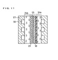
- FIG. 11 is a diagrammatic cross sectional view showing the structure of a unit cell of the polymer electrolyte fuel cell produced using the gas diffusion electrode 54a.
- the gas diffusion electrode 54a and the gas diffusion electrode 24b explained in Embodiment 1 are disposed in intimate contact with the respective sides of a hydrogen ion conductive polymer electrolyte membrane 55 in such a manner that the catalyst layers 53 and 23 face the hydrogen ion conductive polymer electrolyte membrane 55.
- separator plates 57 having gas flow paths 56 formed on one side thereof are disposed outside the electrodes and, through the gas flow paths 56, air as an oxidant gas is passed to the gas diffusion electrode 54a side and hydrogen as a fuel gas is passed to the gas diffusion electrode 24b side.
- Assembling a polymer electrolyte fuel cell by using the gas diffusion electrode 54a as the cathode electrode can achieve a polymer electrolyte fuel cell having a stable voltage over long period of time.
- the amount of penetrating water is suppressed on the inlet side and is facilitated on the outlet side. This suppresses a decrease in cell voltage resulting from the drying or flooding of the hydrogen ion conductive polymer electrolyte membrane.
- the conductive particles are preferably made of carbon.
- This structure enables the provision of a gas diffusion electrode excellent in conductivity. This is because carbon has excellent conductivity.
- the gas diffusion electrodes of Embodiments 1-4 it is preferable to use, as the porous material, carbon paper composed of carbon fiber.
- the gas diffusion electrode to be obtained can be excellent in conductivity. This is because carbon has excellent conductivity.
- the polymer material is preferably fluorocarbon resin.
- fluorocarbon resin is extremely stable electrochemically.
- the present invention also relates to a polymer electrolyte fuel cell comprising a plurality of unit cells stacked, each unit cell comprising: a hydrogen ion conductive polymer electrolyte membrane; a first gas diffusion electrode and a second diffusion electrode, each comprising a catalyst layer and a gas diffusion layer containing a porous material, which sandwich the hydrogen ion conductive polymer electrolyte membrane in such a manner that the catalyst layer faces the hydrogen ion conductive polymer electrolyte membrane; and a first separator plate having a gas flow path for supplying and distributing an oxidant gas to the first gas diffusion electrode and a second separator plate having a gas flow path for supplying and distributing a fuel gas to the second gas diffusion electrode, wherein the first gas diffusion electrode is composed of the gas diffusion electrode in accordance with any one of above Embodiments 1 to 4, and the one end of the first gas diffusion electrode is
- the present invention also relates to a polymer electrolyte fuel cell comprising a plurality of unit cells stacked, each unit cell comprising: a hydrogen ion conductive polymer electrolyte membrane; a first gas diffusion electrode and a second diffusion electrode, each comprising a catalyst layer and a gas diffusion layer containing a porous material, which sandwich the hydrogen ion conductive polymer electrolyte membrane in such a manner that the catalyst layer faces the hydrogen ion conductive polymer electrolyte membrane; and a first separator plate having a gas flow path for supplying and distributing an oxidant gas to the first gas diffusion electrode and a second separator plate having a gas flow path for supplying and distributing a fuel gas to the second gas diffusion electrode, wherein the catalyst layer contains gas diffusing pores for passing the oxidant gas or the fuel gas from the side in contact with the gas diffusion layer towards inside the catalyst layer.
- This fuel cell which is provided with cavities in the plane of the catalyst layer in order to improve gas diffusion performance, has higher cell performance than the cell using a densely formed catalyst layer. The improved performance becomes remarkable when the cell is operated at high current density.
- the inventers of the present invention have found that the utilization of the catalyst does not decrease greatly when the rate of the cavities is made 0.1 to 30%. These cavities can be formed by controlling the drying conditions of the catalyst ink applied on the porous material, without using an additional device.
- the carbon particles carrying catalyst particles When the median diameter of the carbon particles carrying catalyst particles is made 0.1 to 10im, the carbon particles do not become too small or too large, making it possible to form a catalyst layer having stable cavities.
- the catalyst layer can be formed by the step of applying the catalyst ink containing carbon particles carrying catalyst particles, a hydrogen ion conductive polymer electrolyte, and a solvent; and the step of forming a catalyst layer by heating and drying the applied catalyst ink up to two different temperatures.
- the use of two-step drying temperatures can generate cavities in the plane of the catalyst layer without adding a pore-forming agent or the like.
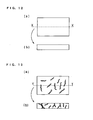
- FIG. 13 shows the structure of the catalyst layer formed according to the present invention
- FIG. 12 shows the structure of the conventional catalyst layer
- FIG. 12 (a) is a top view of the conventional catalyst layer
- FIG. 12 (b) is a cross sectional view taken along the line X-X of (a). It is revealed that the catalyst layer in the conventional case has no cavity in the plane, which indicates that the dense coating film has bee obtained.
- FIG. 13 (a) is a top view of the catalyst layer of the present invention
- FIG. 13 (b) is a cross sectional view taken along the line Y-Y of (a). It is revealed that the catalyst layer of the present invention has cavities at random in the plane, and the cavities penetrate in the thickness direction of the catalyst layer. As a result, the gas diffusibility in the thickness direction of the catalyst layer improves, as compared with the conventional case.
- the cavities can be in the form of cracks or circles, besides the shape shown in FIG. 13.
- the gas diffusion electrode of Embodiment 1 shown in FIG. 2 was produced.
- carbon fiber was arranged inside a molding die having a fixed shape in such a manner that the amount changed in the plane, and was molded by applying a pressure uniformly, thereby preparing a porous material "a" whose pore area changed depending on the position in the plane.
- the surface of the obtained porous material "a” was observed by an optical microscope to find that the mean pore area was 5.23 ⁇ 10 -9 m 2 on one end (R 1 side) and 2.08 ⁇ 10 - 8 m 2 on the other end (L 1 side).
- the thickness was 360 ⁇ m.
- the porous material "a” was divided into R 1 side and L 1 side at the center of the plane, and the amount of penetrating water on each side was evaluated by a gravimetric method (JIS Z0208) to find that the amount was 1.0 ⁇ 10 4 g/m 2 ⁇ 24h on the R 1 side and 2.8 ⁇ 10 4 g/m 2 ⁇ 24h on the L 1 side. This revealed that the amount of penetrating water decreased on the R 1 side and increased on the L 1 side.
- carbon powder having a particle size of 3im (KETJEN BLACK EC manufactured by AKZO chemie, Holland) was soaked in an aqueous solution of platinum chloride to obtain a catalyst body carrying a platinum catalyst on the surface of the carbon powder through a reduction treatment.
- the carbon and the carried platinum were set at a weight ratio of 1:1.
- the obtained catalyst was dispersed in an alcohol dispersion of a polymer electrolyte (Flemion manufactured by Asahi Glass Co., Ltd) to prepare a slurry, and the slurry was applied evenly on a side of the porous material "a", which was to be the gas diffusion layer, to form a catalyst layer, thereby obtaining a gas diffusion electrode "a".
- a polymer electrolyte Femion manufactured by Asahi Glass Co., Ltd
- a porous material °b" was prepared in the same manner except that the amount of the carbon fiber was made constant in the plane.
- the mean pore area of the porous material "b” was uniform in the plane, which was 1.08 ⁇ 10 -8 m 2 , and the thickness thereof was 360im.
- the amount of penetrating water was 1.8 ⁇ 10 4 g/m 2 ⁇ 24h.
- the gas diffusion electrode "b" was obtained from the porous material "b".
- the gas diffusion electrode "a” and the gas diffusion electrode “b” of the same size were laid on both sides of a hydrogen ion conductive polymer electrolyte membrane (Nafion 112 manufactured by Du Pont, U.S.A), which is one size larger than these electrodes, in such a manner that the sides provided with the catalyst layers face the hydrogen ion conductive polymer electrolyte membrane.
- a hydrogen ion conductive polymer electrolyte membrane Nafion 112 manufactured by Du Pont, U.S.A
- hot pressing was applied at 130°C for 5 minutes to prepare an MEA.
- a unit cell was prepared by disposing separator plates on both sides of the MEA, and four unit cells were stacked to obtain a cell stack (the polymer electrolyte fuel cell of the present invention).
- the separator plate was 4 mm-thick carbon-made plate, which had air-tightness.
- gas flow path of 2 mm in width and 1 mm in depth by cutting process.
- the gas diffusion electrode "a" was disposed in such a manner that the R 1 side was on the inlet side and the L 1 side was on the outlet side of the gas flow paths in the separator plates.
- the polymer electrolyte fuel cell operated in a quite stable manner, while maintaining the initial voltage as long as over 3000 hours.
- the reason for this is that the polymer electrolyte fuel cell of the present example was able to discharge excess water content caused by the produced water safely and quickly, while keeping the polymer electrolyte in the humidified condition.
- the pore area is not limited to the one described in the example; the polymer electrolyte fuel cell was able to operate stably as long as the area was larger in the L 1 side than in the R 1 side.
- the gas diffusion electrode of Embodiment 2 shown in FIG. 5 was produced. First, 10 g of acetylene black, 2g of fluorocarbon resin (D-1 manufactured by Daikin Industries, Ltd.), and 50 g of ethanol were mixed and stirred to prepare a dispersion "a" where acetylene black was dispersed in the fluorocarbon resin.
- the porous material "b” impregnated with the dispersion "a” was baked at 350°C to obtain a gas diffusion layer "c".
- the surface of the gas diffusion layer "c” was observed by an optical microscope to find that fluorocarbon resin was retained in the pores, and the acetylene black was dispersed and retained in the fluorocarbon resin. It was also observed that the amount of acetylene black and fluorocarbon resin increased from one end (R 2 side) towards the other end (L 2 side) of the gas diffusion layer.
- the obtained gas diffusion layer "c" was divided into R 2 side and L 2 side, and the amount of penetrating water on each side was evaluated to find that the amount was 0.8 ⁇ 10 4 g/m 2 ⁇ 24h on the R 2 side and 1.8 ⁇ 10 4 g/m 2 ⁇ 24h on the L 2 side. This revealed that the amount of penetrating water decreased on the R 2 side and increased on the L 2 side.
- carbon powder having a particle size not larger than 3im (KETJEN BLACK EC manufactured by AKZO chemie, Holland) was soaked in an aqueous solution of platinum chloride to obtain a catalyst body carrying a platinum catalyst on the surface of the carbon powder through a reduction treatment.
- the carbon and the carried platinum were set at a ratio of 1:1 in weight.
- the obtained catalyst was dispersed in an alcohol dispersion of a polymer electrolyte (Flemion manufactured by Asahi Glass Co., Ltd) to prepare a slurry, and the slurry was applied evenly on a side of the gas diffusion layer "c" to form a catalyst layer, thereby obtaining a gas diffusion electrode "c".
- a polymer electrolyte Femion manufactured by Asahi Glass Co., Ltd
- the gas diffusion electrode "c” and the gas diffusion electrode “b” of the same size were laid on both sides of a hydrogen ion conductive polymer electrolyte membrane (Nafion 112 manufactured by Du Pont, U.S.A), which is one size larger than these electrodes, in such a manner that the sides provided with the catalyst layer face the hydrogen ion conductive polymer electrolyte membrane.
- a hydrogen ion conductive polymer electrolyte membrane Nafion 112 manufactured by Du Pont, U.S.A
- hot pressing was applied at 130°C for 5 minutes to prepare an MEA.
- a unit cell was prepared by disposing separator plates on both sides of the MEA, and four unit cells were stacked to obtain a cell stack (the polymer electrolyte fuel cell of the present invention).
- the separator plate was 4 mm-thick carbon-made plate, which had air-tightness.
- gas flow path of 2 mm in width and 1 mm in depth by cutting process.
- the gas diffusion electrode "c" was disposed in such a manner that the R 2 side was on the inlet side and the L 2 side was on the outlet side of the gas flow paths in the separator plates.
- the polymer electrolyte fuel cell operated in a quite stable manner, while maintaining the initial voltage as long as over 3000 hours.
- the reason for this is that the polymer electrolyte fuel cell of the present example was able to discharge excess water content caused by the produced water safely and quickly, while keeping the polymer electrolyte in the humidified condition.
- the gas diffusion electrode of Embodiment 3 shown in FIG. 7 was produced.
- 10 g of acetylene black (DENKA BLACK manufacture by Denki Kagaku Kogyo K.K.) and 2g (as solid matter) of fluorocarbon resin (D-1 manufactured by Daikin Industries, Ltd.) were mixed and stirred to prepare a dispersion "b" where acetylene black was diffused in the fluorocarbon resin.
- the applied porous material "b” was baked at 350°C to obtain a gas diffusion layer "d".
- the surface of the gas diffusion layer “d” was observed by an optical microscope to find that a layer containing acetylene black and fluorocarbon resin was formed on the porous material "b", and the thickness of the layer was measured by a surface profiler to find that the layer became thinner from one end (R 3 side) towards the other end (L 3 side)of the gas diffusion layer "d" (d1 to d2).
- the obtained gas diffusion layer "d" was divided into R 3 side and L 3 side, and the amount of penetrating water on each side was evaluated.
- the amount was 0.8 ⁇ 10 4 g/m 2 ⁇ 24h on the R 3 side and 1.8 ⁇ 10 4 g/m 2 ⁇ 24h on the L 3 side. This revealed that the amount of penetrating water decreased on the R 3 side and increased on the L 3 side.
- carbon powder having a particle size not karger than 3im (KETJEN BLACK EC manufactured by AKZO chemie, Holland) was soaked in an aqueous solution of platinum chloride to obtain a catalyst body carrying a platinum catalyst on the surface of the carbon powder through a reduction treatment.
- the carbon and the carried platinum were set at a ratio of 1:1 in weight.
- the obtained catalyst was dispersed in an alcohol dispersion of a polymer electrolyte (Flemion manufactured by Asahi Glass Co., Ltd) to prepare a slurry, and the slurry was applied evenly on a side of the gas diffusion layer "d" to form a catalyst layer, thereby obtaining a gas diffusion electrode "d".
- a polymer electrolyte Femion manufactured by Asahi Glass Co., Ltd
- the gas diffusion electrode "d” and the gas diffusion electrode “b” of the same size were laid on both sides of a hydrogen ion conductive polymer electrolyte membrane (Nafion 112 manufactured by Du Pont, U.S.A), which is one size larger than these electrodes, in such a manner that the sides provided with the catalyst layers face the hydrogen ion conductive polymer electrolyte membrane.
- a hydrogen ion conductive polymer electrolyte membrane Nafion 112 manufactured by Du Pont, U.S.A
- hot pressing was applied at 130°C for 5 minutes to prepare an MEA.
- a unit cell was prepared by disposing separator plates on both sides of the MEA, and four unit cells were stacked to obtain a cell stack (the polymer electrolyte fuel cell of the present invention).
- the separator plates was 4 mm-thick carbon-made plate, which had air-tightness.
- gas flow paths of 2 mm in width and 1 mm in depth by cutting process.
- the gas diffusion electrode "d" was disposed in such a manner that the R 3 side was on the inlet side and the L 3 side was on the outlet side of the gas flow paths in the separator plates.
- the polymer electrolyte fuel cell operated in a quite stable manner, while maintaining the initial voltage as long as over 3000 hours.
- the reason for this is that the polymer electrolyte fuel cell of the present example was able to discharge excess water content resulting from the produced water safely and quickly, while keeping the polymer electrolyte in the humidified condition.
- the gas diffusion electrode of Embodiment 4 shown in FIG. 9 was produced.
- 10 g of acetylene black having a mean particle size of 4im (DENKA BLACK manufacture by Denki Kagaku Kogyo K.K.) and 2g of fluorocarbon resin (D-1 manufactured by Daikin Industries, Ltd.) were mixed and stirred to prepare a dispersion "c" where acetylene black was dispersed in the fluorocarbon resin.
- acetylene black having a mean particle size of 1 ⁇ m and 2g of fluorocarbon resin (D-1 manufactured by Daikin Industries, Ltd.) were mixed and stirred to prepare a dispersion "d" where acetylene black was dispersed in the fluorocarbon resin.
- the dispersion "d" was screen-printed on the porous material "b" while changing the pushing pressure from one side to the other side thereof to change the applied amount of the dispersion "d".
- the applied porous material "b” was baked at 350°C to obtain a gas diffusion layer "e".
- the surface of the gas diffusion layer “e” was observed by an optical microscope to find that a layer containing acetylene black and fluorocarbon resin was formed on the porous material "b” and that, in the layer, the acetylene black having a mean particle size of 4im was present uniformly in the plane of the gas diffusion layer "e”; however, the acetylene black having a mean particle size of 1 ⁇ m decreased from one end (R 4 side) towards the other end (L 4 side) of the gas diffusion layer "e".
- the obtained gas diffusion layer "e” was divided into R 4 side and L 4 side, and the amount of penetrating water on each side was evaluated.
- the amount was 0.8 ⁇ 10 4 g/m 2 ⁇ 24h on the R 4 side and 1.8 ⁇ 10 4 g/m 2 ⁇ 24h on the L 4 side. This revealed that the amount of penetrating water decreased on the R 4 side and increased on the L 4 side.
- carbon powder having a particle size not larger than 3im (KETJEN BLACK EC manufactured by AKZO chemie, Holland) was soaked in an aqueous solution of platinum chloride to obtain a catalyst body carrying a platinum catalyst on the surface of the carbon powder through a reduction treatment.
- the carbon and the carried platinum were set at a ratio of 1:1 in weight.
- the obtained catalyst was dispersed in an alcohol dispersion in which a polymer electrolyte was dispersed to prepare a slurry, and the slurry was applied evenly on a side of the gas diffusion layer "e” to form a catalyst layer, thereby obtaining a gas diffusion electrode "e".
- the gas diffusion electrode "e” and the gas diffusion electrode “b” of the same size were laid on both sides of a hydrogen ion conductive polymer electrolyte membrane (Nafion 112 manufactured by Du Pont, U.S.A), which is one size larger than these electrodes, in such a manner that the sides provided with the catalyst layers face the hydrogen ion conductive polymer electrolyte membrane.
- a hydrogen ion conductive polymer electrolyte membrane Nafion 112 manufactured by Du Pont, U.S.A
- hot pressing was applied at 130°C for 5 minutes to prepare an MEA.
- a unit cell was prepared by disposing separator plates on both sides of the MEA, and four unit cells were stacked to obtain a cell stack (the polymer electrolyte fuel cell of the present invention).
- the separator plate was 4 mm-thick carbon-made plate, which had air-tightness.
- gas flow paths of 2 mm in width and 1 mm in depth by cutting process.
- the gas diffusion electrode "e" was disposed in such a manner that the R 4 side was on the inlet side and the L 4 side was on the outlet side of the gas flow paths in the separator plates.
- the polymer electrolyte fuel cell operated in a quite stable manner, maintaining the initial voltage as long as over 3000 hours.
- the reason for this is that the polymer electrolyte fuel cell of the present example was able to discharge excess moisture content resulting from the produced water safely and quickly, while keeping the polymer electrolyte in the humidified condition.
- a polymer electrolyte fuel cell was produced by the same operations as in the above embodiments except that two gas diffusion electrodes "b" were used for the gas diffusion electrodes.
- the polymer electrolyte fuel cell thus completed was operated under the same conditions as in the examples to find that the operation was unstable while decreasing the voltage at the rate of about 1 mv/1h.
- a 5 wt% solution of Nafion manufactured by Aldrich, U.S.A.
- water were mixed in a predetermined ratio into platinum-carried carbon powder (50 wt% platinum) to prepare a catalyst layer ink.
- the catalyst layer ink was divided into five portions and formed into five kinds of catalyst layer inks A, B, C, D, and E containing platinum-carried carbon powder having median diameters of 0.05 ⁇ m, 0.1 ⁇ m, 5 ⁇ m, 10 ⁇ m and 20 ⁇ m, respectively, by using a bead mill disperser (Dispermat SL-C12Z manufactured by GETZMANN, Germany).
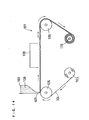
- a catalyst layer ink 106 was put in a tank 102, and the PET film was fed from the unwinding unit 103 of the application device 101 for performing application.
- the catalyst layer ink 106 was applied on the film through a slit-like nozzle 107 from the tank 102.
- the gap between the nozzle and the film was set at 50 to 250 ⁇ m, and the feeding speed was set at 1 m/min.
- the PET film on which the catalyst layer was applied was transferred to a drying room 108 set at a temperature of 60°C, thereby forming the catalyst layer on the film.
- in-plane porosities of the catalyst layer A formed using the catalyst layer ink A, the catalyst layer B formed using the catalyst layer ink B, the catalyst layer C formed using the catalyst layer ink C, the catalyst layer D formed using the catalyst layer ink D, and the catalyst layer E formed using the catalyst layer ink E were measured.
- the porosities were determined by performing an image processing (binary processing, measuring range of about 30 mm 2 , Image Analyzer V10:Toyobo Co. Ltd.).
- Table 1 shows the porosities of the catalyst layers A-E.
- a polymer electrolyte membrane (Nafion 112 manufactured by Du Pont) was sandwiched between two of each catalyst layer A-E using hot pressing to obtain the composites A-E. These composites were sandwiched by carbonpaper (TGP-H-120 manufactured by Toray Industries, Inc.) via gaskets to produce unit cells (the fuel cells of the present invention) A-E containing the electrolyte membrane-electrode assemblies A-E. They were set in a unit cell test device to check characteristics of each cell.
- the fuel electrode was supplied with an imitated reformed gas (carbon dioxide 25%, carbon monoxide 50 ppm, hydrogen balance gas) whereas the air electrode was supplied with air, and the fuel cell was operated under the conditions that cell temperature was 80°C, the utilization of fuel was 80%, and the unitization factor of air was 40%, the imitated reformed gas was humidified to have a dew point of 75°C, and the air was humidified to have a dew point of 60°C.
- an imitated reformed gas carbon dioxide 25%, carbon monoxide 50 ppm, hydrogen balance gas
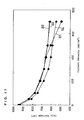
- FIG. 15 shows the current-voltage characteristic of each cell. This has revealed that the performance of the unit cell A using the catalyst layer A having the lowest porosity lowers in the high current density region than the other cells. It has also been found that the performance of the unit cell E using the catalyst layer E having the highest porosity has lowers as a whole.
- FIG. 16 The relation between the cell voltage of each cell at the current density of 0.7 A/cm 2 in FIG. 15 and the porosity of the catalyst layer used in each cell is shown in FIG. 16. This has revealed that the cell performance decreases when the in-plane porosity of the catalyst layer is too low or too high. It has also been found that a high-performing cell can be provided when the in-plane porosity of the catalyst layer is about 0.1 to 15%.
- the catalyst layers C1, C2, and C3 were formed in the same manner as above by setting the drying temperature at 40°C, 60°C, and 80°C, respectively, and their porosities were measured. As a result, it has turned out that the porosity, which was 4% at 60°C becomes 2% in C1 obtained with the drying temperature of 40°C, and becomes 6% in C3 obtained with the drying temperature of 80°C. The performance of the unit cells produced by using these catalyst layers was examined and found that they had the same performance as the unit cell C.
- Adopting this method enables the provision of a high-performing cell by changing the median diameter of the catalyst layer ink and controlling the in-plane porosity of the catalyst layer, without decreasing the utilization of the catalyst.
- the porosity can be also changed by controlling the drying temperature. It is also possible to design a fuel cell according to the purpose by controlling the porosity.
- a PET film is used as the base material; however, a polypropylene (PP) film can be used instead.
- the base material can be other than these. It is also possible to form the film by applying a catalyst layer ink directly onto the carbonpaper which is to be the gas diffusion layer.
- the composition of the catalyst layer ink, the composition of the electrode ink, and the drying conditions are not limited to those in the above examples, and can be selected within the range not losing the effects of the present invention.
- the design of the drying room belonging to the application device 101 used in Example 5 was changed and the room was divided into two stages of the former stage and the latter stage, and the drying temperatures of the first drying room and the second drying room were made to be controlled independently from each other.
- Example 5 application was carried out in the same manner as in Example 5 by using the catalyst layer ink B used in Example 5 and the application device 101 whose design has been modified. At this time, the drying conditions were changed to produce catalyst layers B1-B4, and the porosities in the planes of the catalyst layers were measured in the same manner as in Example 5. The relation between the drying temperature and the porosity in the catalyst layer plane is shown in Table 2. Drying temperature (°C) Porosity (%) First drying room Second drying room Catalyst layer B1 40 80 0.06 Catalyst layer B2 60 80 2.0 Catalyst layer B3 80 80 7.5 Catalyst layer B4 95 80 16
- the in-plane porosity of the catalyst layer can be controlled by controlling the drying temperature even when the same catalyst layer ink is used.
- the reason for this is considered that varying the drying conditions change the agglomeration state of the polymer electrolyte and the catalyst-carried carbon particles in the catalyst layer, thereby changing the crack-like cavities in the plane of the catalyst layer.
- Unit cells B1-B4 were produced in the same manner as in Example 5 by using these catalyst layers B1-B4, and their cell performances were examined.
- the test conditions of the cells were the same as in Example 5.
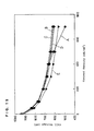
- the current-voltage properties of these unit cells are shown in FIG. 17.
- the unit cell B1 using the catalyst layer B1 having a small porosity in the plate decreases the properties in the high current density region.
- the catalyst layer B1 has the advantage of having a low porosity because the drying temperature is low in the former stage, when the cell is operated at high current density, the produced water remains in the catalyst layer and prevents the diffusion of the reaction gas, which leads to a decrease in cell performance.
- the drying temperature is higher in the former stage than in the latter stage, which causes a sudden solvent volatilization in the former stage, thereby increasing the porosity in the plane of the catalyst layer.
- the catalyst layer gets thicker as a whole, making the catalyst insufficient in the vicinity of the polymer electrolyte, thereby reducing the reaction area. This seems to be the cause of the decrease in the cell performance.
- the drying temperature is set lower in the former stage than in the latter stage so as to obtain a catalyst layer having appropriate porosity, and it is considered that the water produced by the cell reaction is quickly discharged from the pores to the carbon paper as the gas diffusion layer, without preventing the diffusion of the reaction gas, thereby exhibiting high cell performance.
- Employing the method of the present invention can achieve a catalyst layer having appropriate porosity by controlling the drying temperature after the application of the catalyst layer ink. This can provide a higher-performing cell than conventional cells.
- making the area of the pores in the porous material larger from one end towards the other end in the gas diffusion layer can adjust the function of penetrating water in the plane of the gas diffusion layer and can quickly discharge surplus water content resulting from the produced water, while keeping the polymer electrolyte in the humidified condition in the MEA.
- the constitution of a gas diffusion electrode with this gas diffusion layer and the production of a polymer electrolyte fuel cell can achieve a polymer electrolyte fuel cell capable of stable operation over a long period of time.
Landscapes
- Chemical & Material Sciences (AREA)
- Chemical Kinetics & Catalysis (AREA)
- General Chemical & Material Sciences (AREA)
- Electrochemistry (AREA)
- Engineering & Computer Science (AREA)
- Manufacturing & Machinery (AREA)
- Sustainable Development (AREA)
- Sustainable Energy (AREA)
- Life Sciences & Earth Sciences (AREA)
- Materials Engineering (AREA)
- Physics & Mathematics (AREA)
- Thermal Sciences (AREA)
- Inert Electrodes (AREA)
- Fuel Cell (AREA)
Abstract
It has been difficult to keep the voltage of a
polymer electrolyte fuel cell stable for a long period of
time because uniform water content control over the plane
of the membrane-electrode assembly is impossible. A gas
diffusion electrode is produced by forming a conductive
polymer layer composed of conductive particles and a
polymer material on a porous material composed of carbon
fiber, and forming a catalyst layer composed of platinum-carried
carbon particles on the plane of the conductive
polymer layer. The conductive polymer layer is composed of
conductive particles different in particle size, and the
content of the conductive particles having the smaller
particle size is decreased from one end towards the other
end of the gas diffusion electrode.
Description
The present invention relates to a fuel cell
useful as a consumer cogeneration system and an electric
power generator for a mobile untheuch as an automobile, and
further to an electrode used in the fuel cell.
A polymer electrolyte fuel cell makes a supplied
fuel gas such as hydrogen and an oxidant gas such as air
react electrochemically on a catalyst such as platinum,
thereby generating electric power and heat at the same time.
In general, the electrode to which a fuel gas is supplied
is called the anode electrode, and the electrode to which
an oxidant gas is supplied is called the cathode electrode.
A diagrammatic cross sectional view showing the structure
of a unit cell in such a conventional polymer electrolyte
fuel cell is shown in FIG. 1.
In FIG. 1, disposed in intimate contact with both
sides of a hydrogen ion conductive polymer electrolyte
membrane 11 which selectively transports hydrogen ions are
catalyst layers 12 whose main component is carbon powder
carrying a platinum-type metal catalyst. Further disposed
in intimate contact with the outer surfaces of the catalyst
layers 12 are a pair of gas diffusion layers 13 composed of
a porous material having pores. The gas diffusion layer 13
and the catalyst layer 12 constitute a gas diffusion
electrode 14.
Outsides of the gas diffusion electrodes 14 are
disposed separator plates 17 which mechanically fix the
electrolyte membrane-electrode assembly (hereinafter
referred to also as "MEA") composed of the gas diffusion
electrode 14 and the hydrogen ion conductive polymer
electrolyte membrane 11, and electrically connect adjacent
MEAs in series. The separator plate 17 is provided with a
gas flow path 16 at one side for supplying the gas
diffusion electrode 13 with a fuel gas as a reaction gas or
an oxidant gas, and carrying away the water content
produced in the reaction and a surplus gas. This gas flow
path 16 can be formed by causing an additional member
adhered on the separator plate 17; however, in general, a
groove is formed on the surface of the separator plate by a
cutting process to form the gas flow path.
In the cathode electrode of the fuel cell in
operation, an oxidant gas such as air or oxygen, which is a
reaction active material, is diffused into the catalyst
layer through the gas flow path via the gas diffusion layer
13. The surplus water produced in the reaction and
penetrated from the catalyst layer to the gas diffusion
layer is discharged outside the cell through the pores of
the gas diffusion layers together with the surplus gas.
The above-described polymer electrolyte fuel cell
has the property that the hydrogen ion conductive polymer
electrolyte membrane 11 has a higher degree of ion
conductivity with increasing moisture content, which makes
it necessary to keep the hydrogen ion conductive polymer
electrolyte membrane 11 in the humidified condition. For
this reason, it is general to humidify the reaction gas in
advance to have the predetermined moisture level, thereby
securing the moisture retention of the hydrogen ion
conductive polymer electrolyte membrane 11 at the same time
as the supply of the reaction gas.
The water produced as the result of the electrode
reaction is flown from the inlet side to the outlet side of
the gas flow path together with the reaction gas flowing
through the gas flow path of the separator plate, and is
discharged outside the fuel cell in the end. Therefore,
the moisture content of the reaction gas in the fuel cell
differs depending on the position in the flowing direction
of the reaction gas in the gas flow path, which means that
the reaction gas on the outlet side contains more moisture
content and is more humid than the reaction gas on the
inlet side of the gas flow path by the amount of water
produced by the reaction.
Therefore, in the vicinity of the outlet side of
the gas flow path, the function of discharging water from
the gas diffusion layer deteriorates, and in the extreme
case, there is a problem that the surplus water blocks the
pores of the gas diffusion layer, thereby preventing the
diffisability of the reaction gas so as to remarkably
decrease the cell voltage (flooding phenomenon). In
contrast, there is another problem that when a reaction gas
whose humidity has been decreased is supplied from the
inlet side in order to prevent the occurrence of flooding
in the outlet side, the moisture content of the hydrogen
ion conductive polymer electrolyte membrane decreases in
the vicinity of the inlet side, which increases the
conductive resistance of the hydrogen ions, thereby
decreasing the cell voltage. These tendencies become
remarkable when the electrode has a larger area and when
the separator plate has a longer gas flow path.
In view of the above-described prior art problems,
the present invention has an object of providing a gas
diffusion electrode capable of keeping the water content
homogeneous over the entire MEA surface, and also providing
a fuel cell capable of stable operation for a long time of
period.
In general, the catalyst layer in a gas diffusion
electrode is formed as follows. A catalyst ink is prepared
by mixing a dispersion medium such as water or isopropyl
alcohol into a solution or a dispersion solution, which
contains carbon fine powder carrying a noble metal and a
polymer electrolyte having hydrogen ion conductivity. This
catalyst ink is applied on a porous material such as carbon
paper or carbon cloth, which is to be a base material of
the electrode, by using a screen printing method or a spray
method, followed by drying or baking to form the catalyst
layer. Two gas diffusion electrodes each having the gas
diffusion layer and catalyst layer thus prepared are
connected to each other via an electrolyte membrane by
means of a hot press so as to obtain an electrolyte
membrane-electrode assembly (MEA). Besides this method,
there is considered a method where a catalyst ink is
applied on a polymer film or the like by a gravure printing
method or a coater method and dried to form a catalyst
layer, and then the catalyst layer is transferred onto an
electrolyte membrane.
As described above, it is general to make the
catalyst layer used in a fuel cell dense as much as
possible so as not to have cavities such as cracks on the
plane of the catalyst layer, thereby increasing the
utilization of the catalyst. For this reason, a surfactant
or the like is added to the catalyst layer ink in order to
prevent the agglomeration of the carbon particles and to
improve the dispersibility of the carbon particles carrying
the catalyst, and the particle size of the carbon particles
is minimized as less as possible. For example, there is
employed a method where the particle size of the carbon
particles is minimized by using a triturating device having
a high triturating force such as a planetary ball mill.
The occurrence of cracks is prevented by carrying out the
drying process of the applied catalyst layer ink moderately
at a possibly lowest temperature over a long time.
On the other hand, the smooth proceeding of the
electrode reaction in the catalyst layer requires the
efficient supply of the reaction gas into the catalyst
layer. To achieve this, a method is used where a catalyst
layer ink containing a pore-forming agent is applied and
baked so as to form a catalyst layer having micro-level
pores.
It is effective from the viewpoint of the
utilization of the catalyst theelf to make the catalyst
layer dense as much as possible by adding a surfactant to
the catalyst ink, thereby improving the diffusibility and
to decrease the particle size of the carbon particles
carrying the catalyst particles. However, such a dense
catalyst layer is poor in gas diffusibility, particularly
in the direction of thickness. When a polymer electrolyte
fuel cell is operated at high current density, a large
amount of water, which is a reaction product, generates and
resides. This causes the problem of preventing the
reaction gas from being diffused into the catalyst layer,
making it impossible to obtain sufficient cell performance.
Furthermore, in the case of adding a surfactant,
the baking process must be done after the application of
the catalyst layer ink, which increases the number of
process and makes the producing procedure complicated.
Although it is necessary to reduce the particle size of the
carbon particles by a planetary ball mill or the like, too
small carbon particles make the catalyst layer too dense as
described above, thereby deteriorating the cell performance.
It is also possible to improve the gas
diffusibility by adding a pore-forming agent to the
catalyst layer ink; however, this requires the catalyst
layer to be baked after being applied and dried, which is
not preferable because the number of the process is
increased, and the manufacturing procedure complicated.
The case of adding a pore-forming agent has another problem
that the catalyst layer becomes thicker.
Drying the applied catalyst layer ink at a
possibly lowest possible temperature over a long period of
time makes a drying apparatus larger, is not preferable in
terms of cost reduction and the simplification of the
manufacturing procedure, which is not.
In view of the above situations, a method has
been demanded for manufacturing a catalyst layer capable of
keeping the gas diffusibility while possibly minimizing a
decrease in the catalyst utilization of the catalyst in the
catalyst layer.
The present invention is to solve the problem in
the field of a polymer electrolyte fuel cell that a gas
diffusion electrode capable of controlling homogeneous
water content over the entire surface of an MEA, and a
polymer electrolyte fuel cell capable of stable operation
over a long period of time.
The present invention relates to a gas diffusion
electrode comprising a catalyst layer and a gas diffusion
layer containing a porous material, capable of retaining
water content homogeneously in the plane.
In the gas diffusion electrode, it is preferable
that the area of pores in the gas diffusion layer increases
from one end towards the other end of the gas diffusion
electrode in the plane of the gas diffusion layer that is
on the catalyst layer side.
It is preferable that a polymer material
containing conductive particles is included in the pores of
the gas diffusion layer, and the amount of the polymer
material included in the pores decreases from one end
towards the other end of the gas diffusion electrode.
It is preferable that a conductive polymer layer
containing at least conductive particles and a polymer
material is disposed between the gas diffusion layer and
the catalyst layer, and the thickness of the conductive
polymer layer decreases from one end towards the other end
of the gas diffusion electrode.
It is preferable that a conductive polymer layer
containing two kinds of conductive particles different in
particle size and a polymer material is disposed between
the gas diffusion layer and the catalyst layer, and the
content of the conductive particles smaller in particle
size decreases from one end towards the other end of the
gas diffusion electrode.
The present invention also relates to a method
for producing a gas diffusion electrode comprising the
steps of:
mixing a carbon material, a polymer material and a solvent
to prepare a solution; applying the solution in such a
manner that the amount of the solution changes from one end
towards the other end of a gas diffusion layer; and heat-processing
the gas diffusion layer with the solution
applied.
Further, the present invention relates to a
method for producing a gas diffusion electrode comprising
the steps of: mixing carbon materials different in mean
particle size and a solvent to prepare a first solution and
a second solution; applying the first solution from one end
towards the other end of the gas diffusion layer;
applying the second solution on the gas diffusion layer, on which the first solution has been applied, in such a manner that the amount of the second solution changes from one end towards the other end of the gas diffusion layer; and heat-processing the gas diffusion layer with the solutions applied.
applying the second solution on the gas diffusion layer, on which the first solution has been applied, in such a manner that the amount of the second solution changes from one end towards the other end of the gas diffusion layer; and heat-processing the gas diffusion layer with the solutions applied.
The present invention relates to a polymer
electrolyte fuel cell comprising a plurality of unit cells
stacked, each unit cell comprising: a hydrogen ion
conductive polymer electrolyte membrane; a first gas
diffusion electrode and a second diffusion electrode, each
comprising a catalyst layer and a gas diffusion layer
containing a porous material, which sandwich the hydrogen
ion conductive polymer electrolyte membrane in such a
manner that the catalyst layer faces said hydrogen ion
conductive polymer electrolyte membrane; and a first
separator plate having a gas flow path for supplying and
distributing an oxidant gas to the first gas diffusion
electrode and a second separator plate having a gas flow
path for supplying and distributing a fuel gas to the
second gas diffusion electrode, wherein
the first gas diffusion electrode is composed of the above-mentioned gas diffusion electrode, and the one end of the first gas diffusion electrode is positioned on the inlet side and the other end is positioned on the outlet side of the gas flow path of the first separator.
the first gas diffusion electrode is composed of the above-mentioned gas diffusion electrode, and the one end of the first gas diffusion electrode is positioned on the inlet side and the other end is positioned on the outlet side of the gas flow path of the first separator.
Further, the present invention relates to a
polymer electrolyte fuel cell comprising a plurality of
unit cells stacked, each unit cell comprising: a hydrogen
ion conductive polymer electrolyte membrane; a first gas
diffusion electrode and a second diffusion electrode, each
comprising a catalyst layer and a gas diffusion layer
containing a porous material, which sandwich the hydrogen
ion conductive polymer electrolyte membrane in such a
manner that the catalyst layer faces said hydrogen ion
conductive polymer electrolyte membrane; and a first
separator plate having a gas flow path for supplying and
distributing an oxidant gas to the first gas diffusion
electrode and a second separator plate having a gas flow
path for supplying and distributing a fuel gas to the
second gas diffusion electrode, wherein
the catalyst layer contains gas diffusing pores for passing the oxidant gas or the fuel gas from the side in contact with the gas diffusion layer towards inside said catalyst layer.
the catalyst layer contains gas diffusing pores for passing the oxidant gas or the fuel gas from the side in contact with the gas diffusion layer towards inside said catalyst layer.
This polymer electrolyte fuel cell can be
produced by the method comprising the steps of: applying a
catalyst ink containing carbon particles carrying catalyst
particles, a hydrogen ion conductive polymer electrolyte
and a solvent; and heating and drying the applied catalyst
ink up to at least two different temperatures to form a
catalyst layer.
The median diameter of the carbon particles is
preferably 0.1 to 10ìm.
The present invention relates to a gas diffusion
electrode including a gas diffusion layer containing a
porous material and a catalyst layer, thereby securing
homogeneous water content in the plane. Therefore, the gas
diffusion electrode of the present invention can be
modified variously to secure homogeneous water content in
the plane.
The gas diffusion electrode of Embodiment 1 in
accordance with the present invention is characterized in
that the electrode has a gas diffusion layer containing a
porous material and a catalyst layer formed thereon and
that the area of the pores in the plane of the gas
diffusion layer increases from one side towards the other
side of the gas diffusion electrode. This structure
achieves the control of homogeneous water content over the
entire plane of the MEA. This is because the amount of
water penetrating the gas diffusion layer depends on the
area of the pores, and decreases with smaller area and, on
the contrary, increases with larger area. Therefore, when
an MEA is composed with the gas diffusion electrode of the
present invention, the amount of water penetrating in the
plane of the MEA can be controlled by controlling the area
of the pores.
FIG. 2 is a diagrammatic perspective view
conceptually showing a gas diffusion electrode 24a in
Embodiment 1 of the present invention.
As shown in FIG. 2, the gas diffusion electrode
24a is formed by disposing a catalyst layer 23 comprising
carbon particles carrying platinum on one surface of the
gas diffusion layer 22 comprising a porous material
composed of carbon fiber 21. The carbon fiber 21 forms a
pore 211, and as indicated by the arrow in FIG. 2, the area
of the pore 211 increases from one end (R1-side end)
towards the other end (L1-side end) of the gas diffusion
electrode 24a.
On the other hand, FIG. 3 is a diagrammatic
perspective view showing the structure of the conventional
gas diffusion electrode 24b. Although the gas diffusion
electrode 24b has the same fundamental structure as the
electrode 24a, the R1 side and L1 side have identical
construction, and the area of the pore 211 is nearly
uniform in the plane of the gas diffusion electrode.
FIG. 4 is a diagrammatic cross sectional view
showing the structure of a unit cell of the polymer
electrolyte fuel cell manufactured using the gas diffusion
electrodes shown in FIG.s 2 and 3. The gas diffusion
electrode 24a and the gas diffusion electrode 24b are
disposed in intimate contact with the respective sides of a
hydrogen ion conductive polymer electrolyte membrane 25 in
such a manner that the catalyst layers 23 face the hydrogen
ion conductive polymer electrolyte membrane 25.
Furthermore, separator plates 27 having gas flow
paths 26 on one side thereof are disposed outside the
electrodes, and the gas flow paths 26 carry air as an
oxidant gas to the gas diffusion electrode 24a side and
hydrogen as a fuel gas to the gas diffusion electrode 24b
side.
Assembling a polymer electrolyte fuel cell by
using the gas diffusion electrode 24a as the cathode
electrode in this manner can achieve a polymer electrolyte
fuel cell having a stable voltage over a long period of
time. This is because the amount of penetrating water is
decreased on the inlet side and is increased on the outlet
side of the cathode electrode, which suppresses a decrease
in cell voltage resulting from the drying or flooding of
the hydrogen ion conductive polymer electrolyte membrane.
The gas diffusion electrode of Embodiment 2 in
accordance with the present invention includes a gas
diffusion layer containing a porous material, a catalyst
layer formed on the layer, and a polymer material
containing conductive particles included in the pores of
the gas diffusion layer, and the content of the polymer
material decreases from one end towards the other end of
the gas diffusion electrode. Adopting this structure
achieves the control of homogeneous water content over the
entire plane of the MEA. This is because the area of the
pores in the plane of the gas diffusion electrode can be
controlled by the amount of the polymer material present in
the pores, which enables the control of the amount of
penetrating water in the plane of the MEA by the same
action as in Embodiment 1.
FIG. 5 is a diagrammatic perspective view
conceptually showing a gas diffusion electrode 34a in
Embodiment 2 of the present invention.
As shown in FIG. 5, the gas diffusion electrode
34a is formed by disposing a catalyst layer 33 composed of
carbon particles carrying platinum on a surface of the gas
diffusion layer 32 comprising a porous material composed of
carbon fiber 31. The carbon fiber 31 forms a uniform pore
313 in the plane of the gas diffusion layer; a mixture of
conductive particles 311 and a polymer material 312 is
present in the pore; and as indicated by the arrow in FIG.
5, the content of the polymer material 312 decreases from
one end (R2-side end) towards the other end (L2-side end)
of the gas diffusion electrode 34a.
On the other hand, FIG. 6 is a diagrammatic cross
sectional view showing the structure of a unit cell of the
polymer electrolyte fuel cell produced using the gas
diffusion electrode 34a. The gas diffusion electrode 34a
and the gas diffusion electrode 24b mentioned in Embodiment
1 are disposed in intimate contact with the respective
sides of a hydrogen ion conductive polymer electrolyte
membrane 35 in such a manner that the catalyst layers 23
and 33 face the hydrogen ion conductive polymer electrolyte
membrane 35.
Furthermore, separator plates 37 having gas flow
paths 36 on one side thereof are disposed outside the
electrodes and, through the gas flow paths 36, air as an
oxidant gas is passed to the gas diffusion electrode 34a
side and hydrogen as a fuel gas is passed to the gas
diffusion electrode 24b side.
Assembling a polymer electrolyte fuel cell by
using the gas diffusion electrode 34a as the cathode
electrode in this manner can achieve a polymer electrolyte
fuel cell having a stable voltage over a long period of
time. The amount of penetrating water is decreased on the
inlet side and is increased on the outlet side of the gas
flow paths in the cathode electrode. This suppresses a
decrease in cell voltage resulting from the drying or
flooding of the hydrogen ion conductive polymer electrolyte
membrane.
The gas diffusion electrode of Embodiment 3 in
accordance with the present invention includes a gas
diffusion layer having a porous material and a conductive
polymer layer which is formed on the porous material and
composed of at least of conductive particles and a polymer
material, and a catalyst layer formed on the conductive
polymer layer. In other words, the gas diffusion electrode
of Embodiment 3 in accordance with the present invention
includes the gas diffusion layer, the conductive polymer
layer, and the catalyst layer. The thickness of the
conductive polymer layer decreases from one end towards the
other end of the gas diffusion electrode. This structure
achieves the control of homogeneous water content over the
entire plane of the MEA. This is because the amount of
penetrating water depends on the length of the path
(penetrating water path) required for the water to
penetrate the gas diffusion layer, and decreases as the
penetrating water path is longer and increases as the
penetrating water path is shorter. In addition, the amount
of penetrating water in the plane of the MEA can be easily
controlled because the length of the penetrating water path
can be changed by the thickness of the gas diffusion layer.
FIG. 7 is a diagrammatic perspective view
conceptually showing a gas diffusion electrode 44a in
Embodiment 3 in accordance with the present invention.
As shown in FIG. 7, the gas diffusion electrode
44a is constituted by forming a conductive polymer layer 42
composed of conductive particles and a polymer material on
a porous material 41 composed of carbon fiber to obtain a
gas diffusion layer, and disposing a catalyst layer 43
composed of carbon particles carrying platinum on the
surface of the conductive polymer layer 42. As indicated
by the arrow in FIG. 7, the thickness of the conductive
polymer layer 42 decreases from one end (R3-side end)
towards the other end (L3-side end) of the gas diffusion
electrode 44.
On the other hand, FIG. 8 is a diagrammatic cross
sectional view showing the structure of a unit cell of the
polymer electrolyte fuel cell produced using the gas
diffusion electrode 44a. The gas diffusion electrode 44a
and the gas diffusion electrode 24b mentioned in Embodiment
1 are disposed in intimate contact with the respective
sides of a hydrogen ion conductive polymer electrolyte
membrane 45 in such a manner that the catalyst layers 23
and 43 face the hydrogen ion conductive polymer electrolyte
membrane 45.
Furthermore, separator plates 47 having gas flow
paths 46 formed on one side thereof are disposed outside
the electrodes and, through the gas flow paths 46, air as
an oxidant gas is passed to the gas diffusion electrode 44a
side and hydrogen as a fuel gas is passed to the gas
diffusion electrode 24b side.
Assembling a polymer electrolyte fuel cell by
using the gas diffusion electrode 44a as the cathode
electrode in this manner can achieve a polymer electrolyte
fuel cell having a stable voltage over a long period of
time. The amount of penetrating water is decreased on the
inlet side and is increased on the outlet side in the
cathode electrode. This suppresses a decrease in cell
voltage resulting from the drying or flooding of the
hydrogen ion conductive polymer electrolyte membrane.
The gas diffusion electrode of Embodiment 4 of
the present invention includes a gas diffusion layer having
a porous material and a conductive polymer layer composed
of two kinds of conductive particles different in particle
size and a polymer material, and a catalyst layer formed on
the gas diffusion layer. In other words, the gas diffusion
electrode of Embodiment 4 in accordance with the present
invention includes the gas diffusion layer, the conductive
polymer layer, and the catalyst layer. Of the conductive
particles, the proportion of the smaller conductive
particles in the whole conductive particles decreases from
one end towards the other end of the gas diffusion
electrode 44a. This structure achieves the control of
homogeneous water content over the entire plane of the MEA.
In such a gas diffusion layer, cavities formed
mainly between conductive particles function as pores, and
in the case where conductive particles having different
particle sizes are used, the pores are formed in such a
manner that the smaller conductive particles fall into
cavities formed between the larger conductive particles.
Consequently, the area of the pores in the plane of the gas
diffusion layer can be varied by changing the relative
proportion of the particles, thereby controlling the amount
of penetrating water in the plane of the MEA by the same
function as described in Embodiment 1.
FIG. 9 is a diagrammatic perspective view
conceptually showing the structure of a gas diffusion
electrode 54a in Embodiment 4 in accordance with the
present invention, and FIG. 10 is a diagrammatic
perspective view conceptually showing the structure of a
conductive polymer layer 52 in FIG. 9.
As shown in FIG. 9, a gas diffusion electrode 54a
is constituted by forming a conductive polymer layer 52 on
the surface of a porous material 51 composed of carbon
fiber to obtain a gas diffusion layer, and disposing a
catalyst layer 53 composed of carbon particles carrying
platinum on the surface thereof.
As shown in FIG. 10, the conductive polymer layer
52 includes a mixture of conductive particles 511 and 512
different in particle size, and as indicated by the arrow
in FIG. 10, the proportion of the conductive particles 511
of the smaller particle size in the mixture decreases from
one end (R4-side end) towards the other end (L4-side end)
of the gas diffusion electrode 54.
On the other hand, FIG. 11 is a diagrammatic
cross sectional view showing the structure of a unit cell
of the polymer electrolyte fuel cell produced using the gas
diffusion electrode 54a.
The gas diffusion electrode 54a and the gas
diffusion electrode 24b explained in Embodiment 1 are
disposed in intimate contact with the respective sides of a
hydrogen ion conductive polymer electrolyte membrane 55 in
such a manner that the catalyst layers 53 and 23 face the
hydrogen ion conductive polymer electrolyte membrane 55.
Furthermore, separator plates 57 having gas flow
paths 56 formed on one side thereof are disposed outside
the electrodes and, through the gas flow paths 56, air as
an oxidant gas is passed to the gas diffusion electrode 54a
side and hydrogen as a fuel gas is passed to the gas
diffusion electrode 24b side.
Assembling a polymer electrolyte fuel cell by
using the gas diffusion electrode 54a as the cathode
electrode can achieve a polymer electrolyte fuel cell
having a stable voltage over long period of time. In the
cathode electrode, the amount of penetrating water is
suppressed on the inlet side and is facilitated on the
outlet side. This suppresses a decrease in cell voltage
resulting from the drying or flooding of the hydrogen ion
conductive polymer electrolyte membrane.
In the gas diffusion electrodes of Embodiments 2-4,
the conductive particles are preferably made of carbon.
The reason for this is that this structure enables the
provision of a gas diffusion electrode excellent in
conductivity. This is because carbon has excellent
conductivity.
In the gas diffusion electrodes of Embodiments 1-4,
it is preferable to use, as the porous material, carbon
paper composed of carbon fiber. The reason for this is
that the gas diffusion electrode to be obtained can be
excellent in conductivity. This is because carbon has
excellent conductivity.
In the gas diffusion electrodes of Embodiments 2-4,
the polymer material is preferably fluorocarbon resin.
The reason for this is that the use of it can achieve a gas
diffusion electrode capable of the stable control of water
content over a long period of time. This is because
fluorocarbon resin is extremely stable electrochemically.
The gas diffusion electrodes mentioned
hereinbefore can be used suitably in a polymer electrolyte
fuel cell. Therefore, the present invention also relates
to a polymer electrolyte fuel cell comprising a plurality
of unit cells stacked, each unit cell comprising: a
hydrogen ion conductive polymer electrolyte membrane; a
first gas diffusion electrode and a second diffusion
electrode, each comprising a catalyst layer and a gas
diffusion layer containing a porous material, which
sandwich the hydrogen ion conductive polymer electrolyte
membrane in such a manner that the catalyst layer faces the
hydrogen ion conductive polymer electrolyte membrane; and a
first separator plate having a gas flow path for supplying
and distributing an oxidant gas to the first gas diffusion
electrode and a second separator plate having a gas flow
path for supplying and distributing a fuel gas to the
second gas diffusion electrode, wherein the first gas
diffusion electrode is composed of the gas diffusion
electrode in accordance with any one of above Embodiments 1
to 4, and the one end of the first gas diffusion electrode
is positioned on the inlet side and the other end is
positioned on the outlet side of the gas flow path of the
first separator.
The present invention also relates to a polymer
electrolyte fuel cell comprising a plurality of unit cells
stacked, each unit cell comprising: a hydrogen ion
conductive polymer electrolyte membrane; a first gas
diffusion electrode and a second diffusion electrode, each
comprising a catalyst layer and a gas diffusion layer
containing a porous material, which sandwich the hydrogen
ion conductive polymer electrolyte membrane in such a
manner that the catalyst layer faces the hydrogen ion
conductive polymer electrolyte membrane; and a first
separator plate having a gas flow path for supplying and
distributing an oxidant gas to the first gas diffusion
electrode and a second separator plate having a gas flow
path for supplying and distributing a fuel gas to the
second gas diffusion electrode, wherein the catalyst layer
contains gas diffusing pores for passing the oxidant gas or
the fuel gas from the side in contact with the gas
diffusion layer towards inside the catalyst layer.
This fuel cell, which is provided with cavities
in the plane of the catalyst layer in order to improve gas
diffusion performance, has higher cell performance than the
cell using a densely formed catalyst layer. The improved
performance becomes remarkable when the cell is operated at
high current density.
The inventers of the present invention have found
that the utilization of the catalyst does not decrease
greatly when the rate of the cavities is made 0.1 to 30%.
These cavities can be formed by controlling the drying
conditions of the catalyst ink applied on the porous
material, without using an additional device.
When the median diameter of the carbon particles
carrying catalyst particles is made 0.1 to 10im, the carbon
particles do not become too small or too large, making it
possible to form a catalyst layer having stable cavities.
The catalyst layer can be formed by the step of
applying the catalyst ink containing carbon particles
carrying catalyst particles, a hydrogen ion conductive
polymer electrolyte, and a solvent; and the step of forming
a catalyst layer by heating and drying the applied catalyst
ink up to two different temperatures. The use of two-step
drying temperatures can generate cavities in the plane of
the catalyst layer without adding a pore-forming agent or
the like.
FIG. 13 shows the structure of the catalyst layer
formed according to the present invention, and FIG. 12
shows the structure of the conventional catalyst layer.
FIG. 12 (a) is a top view of the conventional catalyst
layer, and FIG. 12 (b) is a cross sectional view taken
along the line X-X of (a). It is revealed that the
catalyst layer in the conventional case has no cavity in
the plane, which indicates that the dense coating film has
bee obtained.
In contrast, FIG. 13 (a) is a top view of the
catalyst layer of the present invention, and FIG. 13 (b) is
a cross sectional view taken along the line Y-Y of (a). It
is revealed that the catalyst layer of the present
invention has cavities at random in the plane, and the
cavities penetrate in the thickness direction of the
catalyst layer. As a result, the gas diffusibility in the
thickness direction of the catalyst layer improves, as
compared with the conventional case. The cavities can be
in the form of cracks or circles, besides the shape shown
in FIG. 13.
The present invention will be described more
specifically using examples as follows; however, the
present invention is not limited thereto.
In the present example, the gas diffusion
electrode of Embodiment 1 shown in FIG. 2 was produced.
First, carbon fiber was arranged inside a molding die
having a fixed shape in such a manner that the amount
changed in the plane, and was molded by applying a pressure
uniformly, thereby preparing a porous material "a" whose
pore area changed depending on the position in the plane.
The surface of the obtained porous material "a"
was observed by an optical microscope to find that the mean
pore area was 5.23×10⁻⁹m2 on one end (R1 side) and 2.08×10-
8m2 on the other end (L1 side). The thickness was 360ìm.
The porous material "a" was divided into R1 side
and L1 side at the center of the plane, and the amount of
penetrating water on each side was evaluated by a
gravimetric method (JIS Z0208) to find that the amount was
1.0×10⁴g/m2·24h on the R1 side and 2.8×10⁴g/m2·24h on the L1
side. This revealed that the amount of penetrating water
decreased on the R1 side and increased on the L1 side.
Next, carbon powder having a particle size of 3im
(KETJEN BLACK EC manufactured by AKZO chemie, Holland) was
soaked in an aqueous solution of platinum chloride to
obtain a catalyst body carrying a platinum catalyst on the
surface of the carbon powder through a reduction treatment.
In this case, the carbon and the carried platinum were set
at a weight ratio of 1:1.
Then, the obtained catalyst was dispersed in an
alcohol dispersion of a polymer electrolyte (Flemion
manufactured by Asahi Glass Co., Ltd) to prepare a slurry,
and the slurry was applied evenly on a side of the porous
material "a", which was to be the gas diffusion layer, to
form a catalyst layer, thereby obtaining a gas diffusion
electrode "a".
On the other hand, a porous material °b" was
prepared in the same manner except that the amount of the
carbon fiber was made constant in the plane. The mean pore
area of the porous material "b" was uniform in the plane,
which was 1.08×10⁻⁸m2, and the thickness thereof was 360im.
The amount of penetrating water was 1.8×10⁴g/m2·24h. In the
same manner as the gas diffusion electrode "a", the gas
diffusion electrode "b" was obtained from the porous
material "b".
The gas diffusion electrode "a" and the gas
diffusion electrode "b" of the same size were laid on both
sides of a hydrogen ion conductive polymer electrolyte
membrane (Nafion 112 manufactured by Du Pont, U.S.A), which
is one size larger than these electrodes, in such a manner
that the sides provided with the catalyst layers face the
hydrogen ion conductive polymer electrolyte membrane.
After silicone rubber gaskets with a thickness of 250im
were positioned on both sides, hot pressing was applied at
130°C for 5 minutes to prepare an MEA.
Then, a unit cell was prepared by disposing
separator plates on both sides of the MEA, and four unit
cells were stacked to obtain a cell stack (the polymer
electrolyte fuel cell of the present invention). Used as
the separator plate was 4 mm-thick carbon-made plate, which
had air-tightness. On the surface in contact with the gas
diffusion electrode were formed gas flow path of 2 mm in
width and 1 mm in depth by cutting process.
On and under the cell stack were disposed and
fixed metal end plates made of SUS304. The gas diffusion
electrode "a" was disposed in such a manner that the R1
side was on the inlet side and the L1 side was on the
outlet side of the gas flow paths in the separator plates.
Next, air was supplied from the inlet side
towards the outlet side of the gas flow paths in the
separator plates in the gas diffusion electrode "a",
whereas hydrogen was supplied from the inlet side towards
the outlet side of the gas flow paths in the separator
plates in the gas diffusion electrode "b", and the fuel
cell was operated under the conditions that the utilization
of oxygen was 40%; the utilization of hydrogen was 70%;
hydrogen humidifying bubbler temperature was 85°C; air
humidifying bubbler temperature was 65°C; and cell
temperature was 75°C.
As a result, the polymer electrolyte fuel cell
operated in a quite stable manner, while maintaining the
initial voltage as long as over 3000 hours. The reason for
this is that the polymer electrolyte fuel cell of the
present example was able to discharge excess water content
caused by the produced water safely and quickly, while
keeping the polymer electrolyte in the humidified condition.
The pore area is not limited to the one described
in the example; the polymer electrolyte fuel cell was able
to operate stably as long as the area was larger in the L1
side than in the R1 side.
In the present example, the gas diffusion
electrode of Embodiment 2 shown in FIG. 5 was produced.
First, 10 g of acetylene black, 2g of fluorocarbon resin
(D-1 manufactured by Daikin Industries, Ltd.), and 50 g of
ethanol were mixed and stirred to prepare a dispersion "a"
where acetylene black was dispersed in the fluorocarbon
resin.
Then, screen printing was applied in such a
manner that the amount of the dispersion "a" differed from
one end towards the other end of the porous material "b"
used in Example 1. The amount of the dispersion "a" was
adjusted by changing the pushing pressure of the squeegee
during the printing from one end towards the other end of
the porous material "b". This printing made the dispersion
"a" impregnated into the porous material "b".
The porous material "b" impregnated with the
dispersion "a" was baked at 350°C to obtain a gas diffusion
layer "c". The surface of the gas diffusion layer "c" was
observed by an optical microscope to find that fluorocarbon
resin was retained in the pores, and the acetylene black
was dispersed and retained in the fluorocarbon resin. It
was also observed that the amount of acetylene black and
fluorocarbon resin increased from one end (R2 side) towards
the other end (L2 side) of the gas diffusion layer.
The obtained gas diffusion layer "c" was divided
into R2 side and L2 side, and the amount of penetrating
water on each side was evaluated to find that the amount
was 0.8×10⁴g/m2·24h on the R2 side and 1.8×10⁴g/m2·24h on
the L2 side. This revealed that the amount of penetrating
water decreased on the R2 side and increased on the L2 side.
Next, carbon powder having a particle size not
larger than 3im (KETJEN BLACK EC manufactured by AKZO
chemie, Holland) was soaked in an aqueous solution of
platinum chloride to obtain a catalyst body carrying a
platinum catalyst on the surface of the carbon powder
through a reduction treatment. In this case, the carbon
and the carried platinum were set at a ratio of 1:1 in
weight.
Then, the obtained catalyst was dispersed in an
alcohol dispersion of a polymer electrolyte (Flemion
manufactured by Asahi Glass Co., Ltd) to prepare a slurry,
and the slurry was applied evenly on a side of the gas
diffusion layer "c" to form a catalyst layer, thereby
obtaining a gas diffusion electrode "c".
The gas diffusion electrode "c" and the gas
diffusion electrode "b" of the same size were laid on both
sides of a hydrogen ion conductive polymer electrolyte
membrane (Nafion 112 manufactured by Du Pont, U.S.A), which
is one size larger than these electrodes, in such a manner
that the sides provided with the catalyst layer face the
hydrogen ion conductive polymer electrolyte membrane.
After silicone rubber gaskets with a thickness of 250im
were positioned on both sides, hot pressing was applied at
130°C for 5 minutes to prepare an MEA.
Then, a unit cell was prepared by disposing
separator plates on both sides of the MEA, and four unit
cells were stacked to obtain a cell stack (the polymer
electrolyte fuel cell of the present invention). Used as
the separator plate was 4 mm-thick carbon-made plate, which
had air-tightness. On the surface in contact with the gas
diffusion electrode were formed gas flow path of 2 mm in
width and 1 mm in depth by cutting process.
On and under the cell stack were disposed and
fixed metal end plates made of SUS304. The gas diffusion
electrode "c" was disposed in such a manner that the R2
side was on the inlet side and the L2 side was on the
outlet side of the gas flow paths in the separator plates.
Next, air was supplied from the inlet side
towards the outlet side of the gas flow paths in the
separator plates in the gas diffusion electrode "c",
whereas hydrogen was supplied from the inlet side towards
the outlet side of the gas flow paths in the separator
plates in the gas diffusion electrode "b", and the fuel
cell was operated under the conditions that the utilization
of oxygen was 40%; the utilization of hydrogen was 70%;
hydrogen humidifying bubbler temperature was 85°C; air
humidifying bubbler temperature was 65°C; and cell
temperature was 75°C.
As a result, the polymer electrolyte fuel cell
operated in a quite stable manner, while maintaining the
initial voltage as long as over 3000 hours. The reason for
this is that the polymer electrolyte fuel cell of the
present example was able to discharge excess water content
caused by the produced water safely and quickly, while
keeping the polymer electrolyte in the humidified condition.
In the present example, the gas diffusion
electrode of Embodiment 3 shown in FIG. 7 was produced.
First, 10 g of acetylene black (DENKA BLACK manufacture by
Denki Kagaku Kogyo K.K.) and 2g (as solid matter) of
fluorocarbon resin (D-1 manufactured by Daikin Industries,
Ltd.) were mixed and stirred to prepare a dispersion "b"
where acetylene black was diffused in the fluorocarbon
resin.
Then, screen printing was applied in such a
manner that the applied amount of the dispersion "b"
differed from one end towards the other end of the porous
material "b" used in Example 1. The dispersion "b" did not
penetrate into the porous material "b" completely and
remained on the upper region as a coating film.
Later, the applied porous material "b" was baked
at 350°C to obtain a gas diffusion layer "d". The surface
of the gas diffusion layer "d" was observed by an optical
microscope to find that a layer containing acetylene black
and fluorocarbon resin was formed on the porous material
"b", and the thickness of the layer was measured by a
surface profiler to find that the layer became thinner from
one end (R3 side) towards the other end (L3 side)of the gas
diffusion layer "d" (d1 to d2).
The obtained gas diffusion layer "d" was divided
into R3 side and L3 side, and the amount of penetrating
water on each side was evaluated. The amount was
0.8×10⁴g/m2·24h on the R3 side and 1.8×10⁴g/m2·24h on the L3
side. This revealed that the amount of penetrating water
decreased on the R3 side and increased on the L3 side.
Next, carbon powder having a particle size not
karger than 3im (KETJEN BLACK EC manufactured by AKZO
chemie, Holland) was soaked in an aqueous solution of
platinum chloride to obtain a catalyst body carrying a
platinum catalyst on the surface of the carbon powder
through a reduction treatment. In this case, the carbon
and the carried platinum were set at a ratio of 1:1 in
weight.
Then, the obtained catalyst was dispersed in an
alcohol dispersion of a polymer electrolyte (Flemion
manufactured by Asahi Glass Co., Ltd) to prepare a slurry,
and the slurry was applied evenly on a side of the gas
diffusion layer "d" to form a catalyst layer, thereby
obtaining a gas diffusion electrode "d".
The gas diffusion electrode "d" and the gas
diffusion electrode "b" of the same size were laid on both
sides of a hydrogen ion conductive polymer electrolyte
membrane (Nafion 112 manufactured by Du Pont, U.S.A), which
is one size larger than these electrodes, in such a manner
that the sides provided with the catalyst layers face the
hydrogen ion conductive polymer electrolyte membrane.
After silicone rubber gaskets with a thickness of 250im
were positioned on both sides, hot pressing was applied at
130°C for 5 minutes to prepare an MEA.
Then, a unit cell was prepared by disposing
separator plates on both sides of the MEA, and four unit
cells were stacked to obtain a cell stack (the polymer
electrolyte fuel cell of the present invention). Used as
the separator plates was 4 mm-thick carbon-made plate,
which had air-tightness. On the surface in contact with
the gas diffusion electrode were formed gas flow paths of 2
mm in width and 1 mm in depth by cutting process.
On and under the cell stack were disposed and
fixed metal end plates made of SUS304. The gas diffusion
electrode "d" was disposed in such a manner that the R3
side was on the inlet side and the L3 side was on the
outlet side of the gas flow paths in the separator plates.
Next, air was supplied from the inlet side
towards the outlet side of the gas flow paths in the
separator plates in the gas diffusion electrode "d",
whereas hydrogen was supplied from the inlet side towards
the outlet side of the gas flow paths in the separator
plates in the gas diffusion electrode "b", and the fuel
cell was operated under the conditions that the utilization
of oxygen was 40%; the utilization of hydrogen was 70%;
hydrogen humidifying bubbler temperature was 85°C; air
humidifying bubbler temperature was 65°C; and cell
temperature was 75°C.
As a result, the polymer electrolyte fuel cell
operated in a quite stable manner, while maintaining the
initial voltage as long as over 3000 hours. The reason for
this is that the polymer electrolyte fuel cell of the
present example was able to discharge excess water content
resulting from the produced water safely and quickly, while
keeping the polymer electrolyte in the humidified condition.
In the present example, the gas diffusion
electrode of Embodiment 4 shown in FIG. 9 was produced.
First, 10 g of acetylene black having a mean particle size
of 4im (DENKA BLACK manufacture by Denki Kagaku Kogyo K.K.)
and 2g of fluorocarbon resin (D-1 manufactured by Daikin
Industries, Ltd.) were mixed and stirred to prepare a
dispersion "c" where acetylene black was dispersed in the
fluorocarbon resin. Furthermore, 10 g of acetylene black
having a mean particle size of 1ìm and 2g of fluorocarbon
resin (D-1 manufactured by Daikin Industries, Ltd.) were
mixed and stirred to prepare a dispersion "d" where
acetylene black was dispersed in the fluorocarbon resin.
After the dispersion "c" was screen-printed on
the porous material "b" at a fixed pushing pressure, the
dispersion "d" was screen-printed on the porous material
"b" while changing the pushing pressure from one side to
the other side thereof to change the applied amount of the
dispersion "d".
The applied porous material "b" was baked at 350°C
to obtain a gas diffusion layer "e". The surface of the
gas diffusion layer "e" was observed by an optical
microscope to find that a layer containing acetylene black
and fluorocarbon resin was formed on the porous material
"b" and that, in the layer, the acetylene black having a
mean particle size of 4im was present uniformly in the
plane of the gas diffusion layer "e"; however, the
acetylene black having a mean particle size of 1ìm
decreased from one end (R4 side) towards the other end (L4
side) of the gas diffusion layer "e".
The obtained gas diffusion layer "e" was divided
into R4 side and L4 side, and the amount of penetrating
water on each side was evaluated. The amount was
0.8×10⁴g/m2·24h on the R4 side and 1.8×10⁴g/m2·24h on the L4
side. This revealed that the amount of penetrating water
decreased on the R4 side and increased on the L4 side.
Next, carbon powder having a particle size not
larger than 3im (KETJEN BLACK EC manufactured by AKZO
chemie, Holland) was soaked in an aqueous solution of
platinum chloride to obtain a catalyst body carrying a
platinum catalyst on the surface of the carbon powder
through a reduction treatment. In this case, the carbon
and the carried platinum were set at a ratio of 1:1 in
weight.
Then, the obtained catalyst was dispersed in an
alcohol dispersion in which a polymer electrolyte was
dispersed to prepare a slurry, and the slurry was applied
evenly on a side of the gas diffusion layer "e" to form a
catalyst layer, thereby obtaining a gas diffusion electrode
"e".
The gas diffusion electrode "e" and the gas
diffusion electrode "b" of the same size were laid on both
sides of a hydrogen ion conductive polymer electrolyte
membrane (Nafion 112 manufactured by Du Pont, U.S.A), which
is one size larger than these electrodes, in such a manner
that the sides provided with the catalyst layers face the
hydrogen ion conductive polymer electrolyte membrane.
After silicone rubber gaskets with a thickness of 250im
were positioned on both sides, hot pressing was applied at
130°C for 5 minutes to prepare an MEA.
Then, a unit cell was prepared by disposing
separator plates on both sides of the MEA, and four unit
cells were stacked to obtain a cell stack (the polymer
electrolyte fuel cell of the present invention). Used as
the separator plate was 4 mm-thick carbon-made plate, which
had air-tightness. On the surface in contact with the gas
diffusion layer were formed gas flow paths of 2 mm in width
and 1 mm in depth by cutting process.
On and under the cell stack were disposed and
fixed metal end plates made of SUS304. The gas diffusion
electrode "e" was disposed in such a manner that the R4
side was on the inlet side and the L4 side was on the
outlet side of the gas flow paths in the separator plates.
Next, air was supplied from the inlet side
towards the outlet side of the gas flow paths in the
separator plates in the gas diffusion electrode "e",
whereas hydrogen was supplied from the inlet side towards
the outlet side of the gas flow paths in the separator
plates in the gas diffusion electrode "b", and the fuel
cell was operated under the conditions that the utilization
of oxygen was 40%; the utilization of hydrogen was 70%;
hydrogen humidifying bubbler temperature was 85°C; air
humidifying bubbler temperature was 65°C; and cell
temperature was 75°C.
As a result, the polymer electrolyte fuel cell
operated in a quite stable manner, maintaining the initial
voltage as long as over 3000 hours. The reason for this is
that the polymer electrolyte fuel cell of the present
example was able to discharge excess moisture content
resulting from the produced water safely and quickly, while
keeping the polymer electrolyte in the humidified condition.
A polymer electrolyte fuel cell was produced by
the same operations as in the above embodiments except that
two gas diffusion electrodes "b" were used for the gas
diffusion electrodes. The polymer electrolyte fuel cell
thus completed was operated under the same conditions as in
the examples to find that the operation was unstable while
decreasing the voltage at the rate of about 1 mv/1h.
The reason for this was that in this polymer
electrolyte fuel cell, the water content of the MEA was
controlled insufficiently and caused gas diffusion failure
due to the drying process of the hydrogen ion conductive
polymer electrolyte membrane on the inlet side, or due to
the flooding on the outlet side.
First, a 5 wt% solution of Nafion (manufactured
by Aldrich, U.S.A.) and water were mixed in a predetermined
ratio into platinum-carried carbon powder (50 wt% platinum)
to prepare a catalyst layer ink. The catalyst layer ink
was divided into five portions and formed into five kinds
of catalyst layer inks A, B, C, D, and E containing
platinum-carried carbon powder having median diameters of
0.05ìm, 0.1ìm, 5ìm, 10ìm and 20ìm, respectively, by using a
bead mill disperser (Dispermat SL-C12Z manufactured by
GETZMANN, Germany).
These kinds of inks were applied on a base
material 104 using an application device 101 shown in FIG.
14. Used as the base material 104 was a film
(thickness:50ìm, width:250 mm) of polyethylene
terephthalate (PET). First, a catalyst layer ink 106 was
put in a tank 102, and the PET film was fed from the
unwinding unit 103 of the application device 101 for
performing application. The catalyst layer ink 106 was
applied on the film through a slit-like nozzle 107 from the
tank 102. The gap between the nozzle and the film was set
at 50 to 250ìm, and the feeding speed was set at 1 m/min.
The PET film on which the catalyst layer was applied was
transferred to a drying room 108 set at a temperature of
60°C, thereby forming the catalyst layer on the film.
Then, in-plane porosities of the catalyst layer A
formed using the catalyst layer ink A, the catalyst layer B
formed using the catalyst layer ink B, the catalyst layer C
formed using the catalyst layer ink C, the catalyst layer D
formed using the catalyst layer ink D, and the catalyst
layer E formed using the catalyst layer ink E were measured.
The porosities were determined by performing an image
processing (binary processing, measuring range of about 30
mm2, Image Analyzer V10:Toyobo Co. Ltd.). Table 1 shows
the porosities of the catalyst layers A-E.
| Median diameter (ìm) | Porosity (%) | |
| Catalyst layer A | 0.05 | 0.05 |
| Catalyst layer B | 0.1 | 1.5 |
| | 5 | 4 |
| | 10 | 15 |
| | 20 | 18 |
A polymer electrolyte membrane (Nafion 112
manufactured by Du Pont) was sandwiched between two of each
catalyst layer A-E using hot pressing to obtain the
composites A-E. These composites were sandwiched by
carbonpaper (TGP-H-120 manufactured by Toray Industries,
Inc.) via gaskets to produce unit cells (the fuel cells of
the present invention) A-E containing the electrolyte
membrane-electrode assemblies A-E. They were set in a unit
cell test device to check characteristics of each cell. In
the produced unit cells, the fuel electrode was supplied
with an imitated reformed gas (carbon dioxide 25%, carbon
monoxide 50 ppm, hydrogen balance gas) whereas the air
electrode was supplied with air, and the fuel cell was
operated under the conditions that cell temperature was
80°C, the utilization of fuel was 80%, and the unitization
factor of air was 40%, the imitated reformed gas was
humidified to have a dew point of 75°C, and the air was
humidified to have a dew point of 60°C.
FIG. 15 shows the current-voltage characteristic
of each cell. This has revealed that the performance of
the unit cell A using the catalyst layer A having the
lowest porosity lowers in the high current density region
than the other cells. It has also been found that the
performance of the unit cell E using the catalyst layer E
having the highest porosity has lowers as a whole.
The relation between the cell voltage of each
cell at the current density of 0.7 A/cm2 in FIG. 15 and the
porosity of the catalyst layer used in each cell is shown
in FIG. 16. This has revealed that the cell performance
decreases when the in-plane porosity of the catalyst layer
is too low or too high. It has also been found that a
high-performing cell can be provided when the in-plane
porosity of the catalyst layer is about 0.1 to 15%.
While using the catalyst layer ink C, the
catalyst layers C1, C2, and C3 were formed in the same
manner as above by setting the drying temperature at 40°C,
60°C, and 80°C, respectively, and their porosities were
measured. As a result, it has turned out that the porosity,
which was 4% at 60°C becomes 2% in C1 obtained with the
drying temperature of 40°C, and becomes 6% in C3 obtained
with the drying temperature of 80°C. The performance of
the unit cells produced by using these catalyst layers was
examined and found that they had the same performance as
the unit cell C.
From the aforementioned results, it is considered
that in a catalyst layer having a small porosity, the cell
characteristics decrease because the produced water remains
inside the catalyst layer when the cell is operated at a
high current density, thereby preventing the diffusion of
the reaction gas. In the catalyst layer having a high
porosity, it is considered that the catalyst layer gets
thicker as a whole, and the catalyst becomes insufficient
in the vicinity of the polymer electrolyte, thereby
decreasing the reaction area.
Regarding the catalyst layers having intermediate
porosities, it is considered that their moderate porosities
(0.1 to 15%) prevent the amount of catalyst from becoming
insufficient in the vicinity of the polymer electrolyte,
and that the water produced by the cell reaction is quickly
discharged from these pores to the carbonpaper as the gas
diffusion layer, without preventing the diffusion of the
reaction gas, thereby exhibiting high cell performances.
Adopting this method enables the provision of a
high-performing cell by changing the median diameter of the
catalyst layer ink and controlling the in-plane porosity of
the catalyst layer, without decreasing the utilization of
the catalyst. The porosity can be also changed by
controlling the drying temperature. It is also possible to
design a fuel cell according to the purpose by controlling
the porosity.
In the present embodiment, a PET film is used as
the base material; however, a polypropylene (PP) film can
be used instead. The base material can be other than
these. It is also possible to form the film by applying a
catalyst layer ink directly onto the carbonpaper which is
to be the gas diffusion layer. The composition of the
catalyst layer ink, the composition of the electrode ink,
and the drying conditions are not limited to those in the
above examples, and can be selected within the range not
losing the effects of the present invention.
The design of the drying room belonging to the
application device 101 used in Example 5 was changed and
the room was divided into two stages of the former stage
and the latter stage, and the drying temperatures of the
first drying room and the second drying room were made to
be controlled independently from each other.
Then, application was carried out in the same
manner as in Example 5 by using the catalyst layer ink B
used in Example 5 and the application device 101 whose
design has been modified. At this time, the drying
conditions were changed to produce catalyst layers B1-B4,
and the porosities in the planes of the catalyst layers
were measured in the same manner as in Example 5. The
relation between the drying temperature and the porosity in
the catalyst layer plane is shown in Table 2.
| Drying temperature (°C) | Porosity (%) | ||
| First drying room | Second drying room | ||
| Catalyst layer B1 | 40 | 80 | 0.06 |
| Catalyst layer B2 | 60 | 80 | 2.0 |
| Catalyst layer B3 | 80 | 80 | 7.5 |
| Catalyst layer B4 | 95 | 80 | 16 |
From the table, it has turned out that the in-plane
porosity of the catalyst layer can be controlled by
controlling the drying temperature even when the same
catalyst layer ink is used. The reason for this is
considered that varying the drying conditions change the
agglomeration state of the polymer electrolyte and the
catalyst-carried carbon particles in the catalyst layer,
thereby changing the crack-like cavities in the plane of
the catalyst layer.
Unit cells B1-B4 were produced in the same manner
as in Example 5 by using these catalyst layers B1-B4, and
their cell performances were examined. The test conditions
of the cells were the same as in Example 5. The current-voltage
properties of these unit cells are shown in FIG. 17.
This indicates that the unit cell B1 using the
catalyst layer B1 having a small porosity in the plate
decreases the properties in the high current density region.
Although the catalyst layer B1 has the advantage of having
a low porosity because the drying temperature is low in the
former stage, when the cell is operated at high current
density, the produced water remains in the catalyst layer
and prevents the diffusion of the reaction gas, which leads
to a decrease in cell performance.
In contrast thereto, in the case of the catalyst
layer B4, the drying temperature is higher in the former
stage than in the latter stage, which causes a sudden
solvent volatilization in the former stage, thereby
increasing the porosity in the plane of the catalyst layer.
Although this increases the porosity, the catalyst layer
gets thicker as a whole, making the catalyst insufficient
in the vicinity of the polymer electrolyte, thereby
reducing the reaction area. This seems to be the cause of
the decrease in the cell performance.
Regarding the catalyst layers B2 and B3 having
intermediate porosities, the drying temperature is set
lower in the former stage than in the latter stage so as to
obtain a catalyst layer having appropriate porosity, and it
is considered that the water produced by the cell reaction
is quickly discharged from the pores to the carbon paper as
the gas diffusion layer, without preventing the diffusion
of the reaction gas, thereby exhibiting high cell
performance.
Employing the method of the present invention can
achieve a catalyst layer having appropriate porosity by
controlling the drying temperature after the application of
the catalyst layer ink. This can provide a higher-performing
cell than conventional cells.
As described hereinbefore, in the gas diffusion
layer using a porous material, making the area of the pores
in the porous material larger from one end towards the
other end in the gas diffusion layer can adjust the
function of penetrating water in the plane of the gas
diffusion layer and can quickly discharge surplus water
content resulting from the produced water, while keeping
the polymer electrolyte in the humidified condition in the
MEA. The constitution of a gas diffusion electrode with
this gas diffusion layer and the production of a polymer
electrolyte fuel cell can achieve a polymer electrolyte
fuel cell capable of stable operation over a long period of
time.
Claims (10)
- A gas diffusion electrode comprising a catalyst layer and a gas diffusion layer containing a porous material, capable of retaining water content homogeneously in the plane.
- The gas diffusion electrode in accordance with claim 1, wherein
the area of pores in said gas diffusion layer increases from one end towards the other end of said gas diffusion electrode in the plane of said gas diffusion layer that is on said catalyst layer side. - The gas diffusion electrode in accordance with claim 1, wherein
a polymer material containing conductive particles is included in the pores of said gas diffusion layer, and
the amount of said polymer material included in said pores decreases from one end towards the other end of said gas diffusion electrode. - The gas diffusion electrode in accordance with claim 1, wherein
a conductive polymer layer containing at least conductive particles and a polymer material is disposed between said gas diffusion layer and said catalyst layer, and
the thickness of the conductive polymer layer decreases from one end towards the other end of said gas diffusion electrode. - The gas diffusion electrode in accordance with claim 1, wherein
a conductive polymer layer containing two kinds of conductive particles different in particle size and a polymer material is disposed between said gas diffusion layer and said catalyst layer, and
the content of the conductive particles smaller in particle size decreases from one end towards the other end of said gas diffusion electrode. - A method for producing a gas diffusion electrode comprising the steps of:mixing a carbon material, a polymer material and a solvent to prepare a solution;applying said solution in such a manner that the amount of said solution changes from one end towards the other end of a gas diffusion layer; andheat-processing said gas diffusion layer with said solution applied.
- A method for producing a gas diffusion electrode comprising the steps of:mixing carbon materials different in mean particle size and a solvent to prepare a first solution and a second solution;applying said first solution from one end towards the other end of said gas diffusion layer;applying said second solution on said gas diffusion layer, on which said first solution has been applied, in such a manner that the amount of said second solution changes from one end towards the other end of said gas diffusion layer; andheat-processing said gas diffusion layer with said solutions applied.
- A polymer electrolyte fuel cell comprising a plurality of unit cells stacked, each unit cell comprising:a hydrogen ion conductive polymer electrolyte membrane;a first gas diffusion electrode and a second diffusion electrode, each comprising a catalyst layer and a gas diffusion layer containing a porous material, which sandwich said hydrogen ion conductive polymer electrolyte membrane in such a manner that said catalyst layer faces said hydrogen ion conductive polymer electrolyte membrane; anda first separator plate having a gas flow path for supplying and distributing an oxidant gas to said first gas diffusion electrode and a second separator plate having a gas flow path for supplying and distributing a fuel gas to said second gas diffusion electrode, wherein
said first gas diffusion electrode is composed of the gas diffusion electrode in accordance with any one of claims 1 to 5, and said one end of said first gas diffusion electrode is positioned on the inlet side and said other end is positioned on the outlet side of said gas flow path of said first separator. - A polymer electrolyte fuel cell comprising a plurality of unit cells stacked, each unit cell comprising:a hydrogen ion conductive polymer electrolyte membrane;a first gas diffusion electrode and a second diffusion electrode, each comprising a catalyst layer and a gas diffusion layer containing a porous material, which sandwich said hydrogen ion conductive polymer electrolyte membrane in such a manner that said catalyst layer faces said hydrogen ion conductive polymer electrolyte membrane; anda first separator plate having a gas flow path for supplying and distributing an oxidant gas to said first gas diffusion electrode and a second separator plate having a gas flow path for supplying and distributing a fuel gas to said second gas diffusion electrode, wherein
said catalyst layer contains gas diffusing pores for passing said oxidant gas or said fuel gas from the side in contact with said gas diffusion layer towards inside said catalyst layer. - A method for producing the polymer electrolyte fuel cell of claim 9 comprising the steps of:applying a catalyst ink containing carbon particles carrying catalyst particles, a hydrogen ion conductive polymer electrolyte and a solvent; andheating and drying said applied catalyst ink up to at least two different temperatures to form a catalyst layer.
Applications Claiming Priority (5)
| Application Number | Priority Date | Filing Date | Title |
|---|---|---|---|
| JP2001064573 | 2001-03-08 | ||
| JP2001064573A JP4876318B2 (en) | 2001-03-08 | 2001-03-08 | Polymer electrolyte fuel cell and manufacturing method thereof |
| JP2001124370 | 2001-04-23 | ||
| JP2001124370A JP4880131B2 (en) | 2001-04-23 | 2001-04-23 | Gas diffusion electrode and fuel cell using the same |
| PCT/JP2002/002045 WO2002073721A1 (en) | 2001-03-08 | 2002-03-05 | Gas diffusion electrode and fuel cell using this |
Publications (2)
| Publication Number | Publication Date |
|---|---|
| EP1357617A1 true EP1357617A1 (en) | 2003-10-29 |
| EP1357617A4 EP1357617A4 (en) | 2008-03-26 |
Family
ID=26610846
Family Applications (1)
| Application Number | Title | Priority Date | Filing Date |
|---|---|---|---|
| EP02702748A Withdrawn EP1357617A4 (en) | 2001-03-08 | 2002-03-05 | GAS DIFFUSION ELECTRODE AND FUEL CELL USING THE SAME |
Country Status (5)
| Country | Link |
|---|---|
| US (1) | US6991870B2 (en) |
| EP (1) | EP1357617A4 (en) |
| KR (2) | KR100474941B1 (en) |
| CN (1) | CN1263186C (en) |
| WO (1) | WO2002073721A1 (en) |
Families Citing this family (33)
| Publication number | Priority date | Publication date | Assignee | Title |
|---|---|---|---|---|
| US20040001991A1 (en) * | 2002-07-01 | 2004-01-01 | Kinkelaar Mark R. | Capillarity structures for water and/or fuel management in fuel cells |
| AU2002364240A1 (en) * | 2002-06-28 | 2004-01-19 | Foamex L.P. | Gas diffusion layer for fuel cells |
| AU2003297783A1 (en) * | 2002-12-27 | 2004-07-29 | Foamex L.P. | Gas diffusion layer containing inherently conductive polymer for fuel cells |
| JP3985714B2 (en) * | 2003-04-02 | 2007-10-03 | セイコーエプソン株式会社 | Manufacturing method of fuel cell |
| EP1627444A2 (en) * | 2003-05-09 | 2006-02-22 | Foamex L.P. | Gas diffusion layer having carbon particle mixture |
| US7598054B2 (en) * | 2003-10-31 | 2009-10-06 | Immunetics, Inc. | Rapid peptidoglycan-based assay for detection of bacterial contamination of platelets |
| JP4131408B2 (en) * | 2004-02-13 | 2008-08-13 | アイシン精機株式会社 | Method for producing polymer electrolyte fuel cell |
| KR100670279B1 (en) * | 2005-01-26 | 2007-01-16 | 삼성에스디아이 주식회사 | Thin membrane electrode assembly for fuel cell and fuel cell using same |
| KR100696621B1 (en) | 2005-05-11 | 2007-03-19 | 삼성에스디아이 주식회사 | Electrode base material for fuel cell, manufacturing method thereof and membrane-electrode assembly comprising same |
| US7879029B2 (en) * | 2005-12-30 | 2011-02-01 | Biosense Webster, Inc. | System and method for selectively energizing catheter electrodes |
| KR20070106200A (en) * | 2006-04-28 | 2007-11-01 | 삼성에스디아이 주식회사 | Membrane-electrode assembly for fuel cell, manufacturing method thereof and fuel cell system comprising same |
| JP5031302B2 (en) * | 2006-09-07 | 2012-09-19 | 株式会社ノリタケカンパニーリミテド | Method for forming gas diffusion electrode |
| JP5332092B2 (en) * | 2006-09-11 | 2013-11-06 | トヨタ自動車株式会社 | Fuel cell |
| KR20080105255A (en) | 2007-05-30 | 2008-12-04 | 현대자동차주식회사 | 5-layer MEA manufacturing method with improved electrical conductivity |
| KR101250743B1 (en) * | 2007-06-12 | 2013-04-03 | 캐논 가부시끼가이샤 | Method of manufacturing membrane electrode assembly and method of manufacturing fuel cell |
| TWI398982B (en) * | 2007-08-15 | 2013-06-11 | Univ Feng Chia | Modified carbonized substrate and its manufacturing method and use |
| KR100957302B1 (en) * | 2007-09-07 | 2010-05-12 | 현대자동차주식회사 | Manufacturing method of membrane-electrode assembly for fuel cell |
| US7741243B2 (en) * | 2007-10-05 | 2010-06-22 | Canon Kabushiki Kaisha | Production method of catalyst layer |
| JP2012521070A (en) | 2009-03-18 | 2012-09-10 | ユーティーシー パワー コーポレイション | Fuel cell with purge manifold |
| TWI396323B (en) * | 2009-12-16 | 2013-05-11 | Univ Nat Sun Yat Sen | Structure and manufacturing method of fuel cell electrode |
| US20110159403A1 (en) * | 2010-03-02 | 2011-06-30 | Ford Global Technologies, Llc | Layered Catalyst Assembly and Electrode Assembly Employing the Same |
| US20110159400A1 (en) * | 2010-03-02 | 2011-06-30 | Ford Global Technologies, Llc | Hybrid Catalyst System and Electrode Assembly Employing the Same |
| JP5534906B2 (en) | 2010-03-31 | 2014-07-02 | Jx日鉱日石エネルギー株式会社 | Membrane electrode assembly and fuel cell |
| KR101162876B1 (en) | 2010-11-03 | 2012-07-05 | 삼성에스디아이 주식회사 | Fuel cell module and manufacturing method of the same |
| JP5736232B2 (en) * | 2011-05-17 | 2015-06-17 | 東芝燃料電池システム株式会社 | Polymer electrolyte fuel cell |
| CN103855407B (en) * | 2012-12-04 | 2016-05-25 | 中国科学院大连化学物理研究所 | A kind of membrane electrode that improves voltage distribution uniformity |
| KR101724960B1 (en) | 2015-12-08 | 2017-04-10 | 현대자동차주식회사 | Fuel cell and control method for the same |
| JP6465237B1 (en) * | 2017-10-30 | 2019-02-06 | 凸版印刷株式会社 | Electrode catalyst layer, membrane electrode assembly, and polymer electrolyte fuel cell |
| CN112838234B (en) * | 2019-11-22 | 2022-03-11 | 西部金属材料股份有限公司 | Metal fiber flow field and metal fiber gas diffusion layer integrated sintered bipolar plate |
| CN111146467A (en) * | 2019-12-11 | 2020-05-12 | 青岛科技大学 | Preparation method of pore-size-gradient microporous layered gas diffusion layer |
| CN112522734A (en) * | 2020-11-17 | 2021-03-19 | 广东省科学院新材料研究所 | Porous electrode for electrolytic gas production in liquid environment and preparation method thereof |
| CN112599792B (en) * | 2020-12-14 | 2022-07-19 | 中国科学院大连化学物理研究所 | A kind of preparation method of fuel cell membrane electrode catalytic layer |
| DE112021005240T5 (en) * | 2021-01-22 | 2023-09-14 | Robert Bosch Gesellschaft mit beschränkter Haftung | Gas diffusion layers of a fuel cell |
Family Cites Families (15)
| Publication number | Priority date | Publication date | Assignee | Title |
|---|---|---|---|---|
| JPS61269857A (en) | 1985-05-24 | 1986-11-29 | Toshiba Corp | Fuel cell |
| JPH02162650A (en) | 1988-12-15 | 1990-06-22 | Mitsubishi Electric Corp | Manufacture of catalyst |
| JP3245929B2 (en) * | 1992-03-09 | 2002-01-15 | 株式会社日立製作所 | Fuel cell and its application device |
| JPH07254419A (en) * | 1994-03-15 | 1995-10-03 | Tanaka Kikinzoku Kogyo Kk | Electrode for polymer electrolyte type electrochemical cell and method for producing the same |
| JPH08264192A (en) | 1995-03-23 | 1996-10-11 | Fuji Electric Co Ltd | Fuel cell electrode base material and method for manufacturing the same |
| US5607785A (en) * | 1995-10-11 | 1997-03-04 | Tanaka Kikinzoku Kogyo K.K. | Polymer electrolyte electrochemical cell and process of preparing same |
| US5672439A (en) * | 1995-12-18 | 1997-09-30 | Ballard Power Systems, Inc. | Method and apparatus for reducing reactant crossover in an electrochemical fuel cell |
| JPH09283153A (en) * | 1996-04-09 | 1997-10-31 | Ishikawajima Harima Heavy Ind Co Ltd | Solid polymer electrolyte fuel cell |
| US5677074A (en) * | 1996-06-25 | 1997-10-14 | The Dais Corporation | Gas diffusion electrode |
| US5783325A (en) * | 1996-08-27 | 1998-07-21 | The Research Foundation Of State Of New York | Gas diffusion electrodes based on poly(vinylidene fluoride) carbon blends |
| IT1291603B1 (en) * | 1997-04-18 | 1999-01-11 | De Nora Spa | GASEOUS DIFFUSION ELECTRODES FOR POLYMER DIAPHRAGM FUEL CELL |
| KR100201572B1 (en) * | 1997-04-18 | 1999-06-15 | 최수현 | Electrode Manufacturing Method of Fuel Cell by Mixing Method of Coating and Rolling |
| DE19751297A1 (en) * | 1997-11-19 | 1999-05-20 | Siemens Ag | Carbon gas diffusion electrode for batteries and fuel cells |
| CA2290089A1 (en) * | 1998-11-24 | 2000-05-24 | Ballard Power Systems Inc. | Electrochemical fuel cell with an electrode having an in-plane nonuniform structure |
| JP4528386B2 (en) | 1999-08-18 | 2010-08-18 | 株式会社東芝 | Solid polymer fuel cell and manufacturing method thereof |
-
2002
- 2002-03-05 CN CNB028005155A patent/CN1263186C/en not_active Expired - Lifetime
- 2002-03-05 KR KR10-2002-7014600A patent/KR100474941B1/en not_active Expired - Fee Related
- 2002-03-05 EP EP02702748A patent/EP1357617A4/en not_active Withdrawn
- 2002-03-05 KR KR10-2004-7018722A patent/KR100497302B1/en not_active Expired - Lifetime
- 2002-03-05 US US10/296,338 patent/US6991870B2/en not_active Expired - Lifetime
- 2002-03-05 WO PCT/JP2002/002045 patent/WO2002073721A1/en not_active Ceased
Also Published As
| Publication number | Publication date |
|---|---|
| KR20050004167A (en) | 2005-01-12 |
| CN1263186C (en) | 2006-07-05 |
| KR20020093107A (en) | 2002-12-12 |
| US20030087145A1 (en) | 2003-05-08 |
| KR100474941B1 (en) | 2005-03-10 |
| KR100497302B1 (en) | 2005-06-23 |
| CN1457521A (en) | 2003-11-19 |
| WO2002073721A1 (en) | 2002-09-19 |
| EP1357617A4 (en) | 2008-03-26 |
| US6991870B2 (en) | 2006-01-31 |
Similar Documents
| Publication | Publication Date | Title |
|---|---|---|
| US6991870B2 (en) | Gas diffusion electrode and fuel cell using this | |
| EP1063717B1 (en) | Stable and high-performance fuel cell | |
| KR100474940B1 (en) | Polymer electrolyte fuel cell | |
| EP1304753B1 (en) | Polyelectrolyte fuel cell | |
| EP0872907B1 (en) | Fuel cell | |
| KR100513183B1 (en) | Fuel cell | |
| JP4233208B2 (en) | Fuel cell | |
| JP2842150B2 (en) | Polymer electrolyte fuel cell | |
| JPWO2001017047A1 (en) | Polymer electrolyte fuel cell | |
| KR100532897B1 (en) | Electrode for fuel cell and fuel cell | |
| KR20160008205A (en) | Self-wetting membrane electrode unit and fuel cell having such a unit | |
| EP1739772B1 (en) | Gas diffusion layer and fuel cell using same | |
| CN113544884B (en) | Cathode catalyst layer of fuel cell and fuel cell | |
| CN100438185C (en) | High polymer electrolyte type fuel cell and manufacturing method therefor | |
| JP2001006708A (en) | Solid high polymer fuel cell | |
| KR102176856B1 (en) | Gas diffusion layer for fuel cell, membbrane electrode assembly comprising same, fuel cell comprising same and method for manufacturing the gas diffusion layer for fuel cell | |
| JP3562809B2 (en) | Gas diffusion layer for polymer electrolyte fuel cell, electrolyte membrane-electrode assembly using the same, and polymer electrolyte fuel cell | |
| JP4880131B2 (en) | Gas diffusion electrode and fuel cell using the same | |
| JP2004207231A (en) | Electrolyte membrane-electrode assembly for fuel cell and method of operating fuel cell using the same | |
| US7625661B2 (en) | Diffusion media with continuous micro-porous layers incorporating non-uniformity | |
| US8377601B2 (en) | Direct oxidation fuel cell | |
| US10297850B2 (en) | Membrane electrode assembly | |
| JP2002289201A (en) | Fuel cell | |
| CN217955916U (en) | Fuel cell unit and fuel cell system |
Legal Events
| Date | Code | Title | Description |
|---|---|---|---|
| PUAI | Public reference made under article 153(3) epc to a published international application that has entered the european phase |
Free format text: ORIGINAL CODE: 0009012 |
|
| 17P | Request for examination filed |
Effective date: 20021119 |
|
| AK | Designated contracting states |
Kind code of ref document: A1 Designated state(s): AT BE CH CY DE DK ES FI FR GB GR IE IT LI LU MC NL PT SE TR |
|
| A4 | Supplementary search report drawn up and despatched |
Effective date: 20080225 |
|
| RAP1 | Party data changed (applicant data changed or rights of an application transferred) |
Owner name: PANASONIC CORPORATION |
|
| 17Q | First examination report despatched |
Effective date: 20100924 |
|
| STAA | Information on the status of an ep patent application or granted ep patent |
Free format text: STATUS: THE APPLICATION HAS BEEN WITHDRAWN |
|
| 18W | Application withdrawn |
Effective date: 20150310 |