EP1357449A1 - Method for modeling complex, three dimensional tool paths through a workpiece - Google Patents
Method for modeling complex, three dimensional tool paths through a workpiece Download PDFInfo
- Publication number
- EP1357449A1 EP1357449A1 EP03075965A EP03075965A EP1357449A1 EP 1357449 A1 EP1357449 A1 EP 1357449A1 EP 03075965 A EP03075965 A EP 03075965A EP 03075965 A EP03075965 A EP 03075965A EP 1357449 A1 EP1357449 A1 EP 1357449A1
- Authority
- EP
- European Patent Office
- Prior art keywords
- dimensional
- tool
- workpiece
- slices
- tool path
- Prior art date
- Legal status (The legal status is an assumption and is not a legal conclusion. Google has not performed a legal analysis and makes no representation as to the accuracy of the status listed.)
- Ceased
Links
Images


Classifications
-
- G—PHYSICS
- G05—CONTROLLING; REGULATING
- G05B—CONTROL OR REGULATING SYSTEMS IN GENERAL; FUNCTIONAL ELEMENTS OF SUCH SYSTEMS; MONITORING OR TESTING ARRANGEMENTS FOR SUCH SYSTEMS OR ELEMENTS
- G05B19/00—Program-control systems
- G05B19/02—Program-control systems electric
- G05B19/18—Numerical control [NC], i.e. automatically operating machines, in particular machine tools, e.g. in a manufacturing environment, so as to execute positioning, movement or co-ordinated operations by means of program data in numerical form
- G05B19/41—Numerical control [NC], i.e. automatically operating machines, in particular machine tools, e.g. in a manufacturing environment, so as to execute positioning, movement or co-ordinated operations by means of program data in numerical form characterised by interpolation, e.g. the computation of intermediate points between programmed end points to define the path to be followed and the rate of travel along that path
-
- G—PHYSICS
- G05—CONTROLLING; REGULATING
- G05B—CONTROL OR REGULATING SYSTEMS IN GENERAL; FUNCTIONAL ELEMENTS OF SUCH SYSTEMS; MONITORING OR TESTING ARRANGEMENTS FOR SUCH SYSTEMS OR ELEMENTS
- G05B19/00—Program-control systems
- G05B19/02—Program-control systems electric
- G05B19/18—Numerical control [NC], i.e. automatically operating machines, in particular machine tools, e.g. in a manufacturing environment, so as to execute positioning, movement or co-ordinated operations by means of program data in numerical form
- G05B19/4097—Numerical control [NC], i.e. automatically operating machines, in particular machine tools, e.g. in a manufacturing environment, so as to execute positioning, movement or co-ordinated operations by means of program data in numerical form characterised by using design data to control NC machines, e.g. CAD/CAM
-
- G—PHYSICS
- G05—CONTROLLING; REGULATING
- G05B—CONTROL OR REGULATING SYSTEMS IN GENERAL; FUNCTIONAL ELEMENTS OF SUCH SYSTEMS; MONITORING OR TESTING ARRANGEMENTS FOR SUCH SYSTEMS OR ELEMENTS
- G05B2219/00—Program-control systems
- G05B2219/30—Nc systems
- G05B2219/35—Nc in input of data, input till input file format
- G05B2219/35148—Geometric modeling for swept volume of moving solids
-
- Y—GENERAL TAGGING OF NEW TECHNOLOGICAL DEVELOPMENTS; GENERAL TAGGING OF CROSS-SECTIONAL TECHNOLOGIES SPANNING OVER SEVERAL SECTIONS OF THE IPC; TECHNICAL SUBJECTS COVERED BY FORMER USPC CROSS-REFERENCE ART COLLECTIONS [XRACs] AND DIGESTS
- Y02—TECHNOLOGIES OR APPLICATIONS FOR MITIGATION OR ADAPTATION AGAINST CLIMATE CHANGE
- Y02P—CLIMATE CHANGE MITIGATION TECHNOLOGIES IN THE PRODUCTION OR PROCESSING OF GOODS
- Y02P90/00—Enabling technologies with a potential contribution to greenhouse gas [GHG] emissions mitigation
- Y02P90/02—Total factory control, e.g. smart factories, flexible manufacturing systems [FMS] or integrated manufacturing systems [IMS]
Definitions
- the present disclosure relates generally to computer aided design and manufacturing (CAD/CAM) and, more particularly, to a method for modeling complex, three dimensional tool paths through a workpiece.
- CAD/CAM computer aided design and manufacturing
- NC milling technology In numerically controlled (NC) milling technology, a tool or cutter is directed through a set of pre-recorded sequential trajectories to fabricate a desired shape from raw stock. This technology is capable of producing free-formed, sculptured surfaces while maintaining tight milling error tolerances. Consequently, NC milling technology is widely used in the production of complicated, high-precision products such as molds, dies, aerospace parts, etc. These products, especially molds and dies, typically influence many other subsequent production processes. In order to improve the accuracy and reliability of NC milling, certain verification methods are used to check milling tool paths for potential problems such as milling error, collision, and improper machining parameters, among others.
- Analytical methods are implemented to graphically simulate the milling process off-line and, in some cases, verify milling error, tool assembly collision, and other machining parameters.
- NC programmers can visualize the shape of milled parts and understand potential problems in an efficient, less expensive, and more accurate way.
- Direct solid modeling is one approach used in simulating the material removal process, implemented through direct Boolean difference operations between a solid model of the workpiece and solid models of swept volumes of the milling tool.
- the milling process may be realistically simulated, resulting in an explicit solid model of the milled workpiece that may be graphically presented and reviewed. Since the milled part is explicitly defined by a solid representation, a subsequent analysis and computation of milling error, volume removal rate, or milling dynamics can be readily performed.
- the direct solid modeling approach is theoretically capable of presenting accurate results of NC verification, the applications thereof remain limited. Generally, such limitations result from the complexity of Boolean difference operations between solid entities.
- the Boolean difference operation requires computation of the intersection between the shells of two solid entities.
- Another approach is to represent simple three-dimensional tool shapes (e.g., spheres, cylinders) as a two-dimensional profile that is extruded through a workpiece to provide a real world representation.
- simple profile extrusion becomes inapplicable when the tool shape and the tool path are complex. Accordingly, it is desirable to be able to simulate the material removal process for complex tool shapes and paths while overcoming the above limitations.
- the method includes creating a three-dimensional tool model and defining a tool path through the workpiece.
- a plurality of two-dimensional slices is then created from the three-dimensional tool model, and each of the plurality of two-dimensional slices is passed along the tool path and through the workpiece. Material from the workpiece coming into contact with each of the plurality of two-dimensional slices passed therethrough is subtracted from the workpiece.
- the method further includes positioning the three-dimensional tool model at one end of the tool path prior to creating the plurality of two-dimensional slices.
- the plurality of two-dimensional slices are taken along corresponding slice planes, each of the slice planes being parallel to one another.
- the three-dimensional tool model is positioned at said one end of the tool path at a reference point on the three-dimensional tool model.
- a three dimensional (3D) tool model of complex shape is broken down into a series of two dimensional (2D)"slices" or layers.
- the slices are then each swept along a defined tool path and through the workpiece. With the passing of each slice, material that the slice intersects with on the workpiece is subtracted (i.e., removed).
- the greater the number of 2D slices used the greater the accuracy of the model since, as the number of 2D slices approaches infinity, the tool representation becomes a true 3D solid.
- FIG. 1 there is shown a block diagram that illustrates a method 100 for modeling complex, three dimensional tool paths through a virtual workpiece or 3D solid model representative of an actual workpiece.
- a three dimensional tool model is computer generated and the tool geometry is defined.
- a tool path for the tool model is defined with respect to the virtual workpiece, as shown in block 104.
- the tool model is positioned at a first end of the tool path such that a reference point on the tool model corresponds to the point at the first end of the tool path.
- a series of individual, 2D slices are created along the 3D model, as shown in block 108.
- the 2D slices are taken along parallel planes with respect to one another. However, this need not be the case. For example, radial, irregular or non-parallel 2D slices may be appropriate, depending upon the specific tool path through the virtual workpiece.
- each 2D slice created above is passed along the tool path and through the virtual workpiece, as shown in block 110.
- the material within the workpiece that each 2D slice comes into contact with as it is swept along the tool path is subtracted.
- the material removal simulation is complete. Again, the particular level of accuracy of the simulation will depend upon how many 2D slices are used. Generally speaking, the desired number of 2D slices will depend upon the particular project associated with the virtual machining. However, the greater the number of slices used, the slower the processing time of the computer.
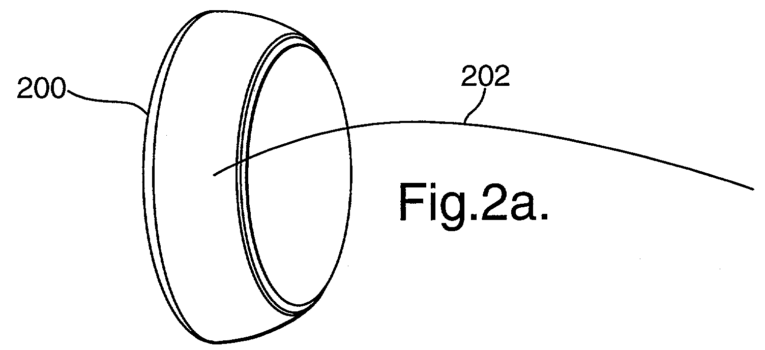
- Figure 2(a) shows a perspective view of an irregularly shaped, 3D tool model 200.
- a determined tool path 202 is delineated from a reference point on one face of the tool model 200.
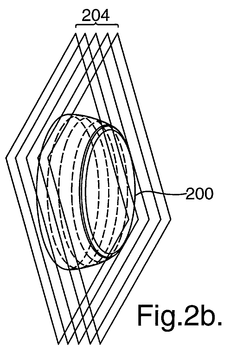
- Figure 2(b) there is shown another perspective view of the tool model 200, along with a series of exemplary slices taken across slice planes 204.
- FIG 2(c) the slice planes 204 are shown in a side view thereof to illustrate the irregular shape of the tool model 200.
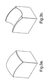
- Figure 3(a) illustrates an exemplary model of a workpiece or virtual workpiece 300 prior to the passing of the slice planes 204 therethrough along the tool path 202.
- the end result of the simulated removal process of material in accordance with method 100 is shown in Figure 3(b).
- a horizontally structured modeling of the planes allows for the independent addition or subtraction of additional features.
- Such a horizontally structured coordinate system facilitates model generation wherein a feature is placed and positioned independently according to subsequently constrained references (e.g., coordinate system(s), datums, and the like). If a parent feature is removed, there will be no loss of any associated child features therewith.
- This independence of the various modeling elements also allows for the addition, subtraction, and reordering of new or existing modeling elements. Additional information regarding horizontally structured CAD/CAM and modeling systems may be found in commonly assigned U.S. Patent , U.S. Patent Application Serial Number 09/483,722 by Khurana et al., and U.S. Patent , U.S.
- Patent Application Serial Number 09/483301 by Khurana et al. the contents of which are incorporated herein by reference in their entirety. Additional features of horizontally structured modeling are described in commonly assigned United States Patent No. , United States Patent Application Serial No. 10/032,960, Publication No. US 2002-0133803 A1 filed October 24, 2001, entitled “Enhancement to Horizontally-Structured CAD/CAM Modeling", by Diane M. Landers et al. and United States Patent No. , United States Patent Application Serial No. 10/033,163, filed October 24, 2001, Attorney Docket No. DP-304037, Publication No. US 2002-0133267 A1 entitled “Enhancement to Horizontally Structured Manufacturing Process Modeling", by Diane M. Landers et al., the disclosures of which are incorporated by reference herein in their entirety.
- the disclosed invention may be embodied in the form of computer-implemented processes and apparatuses for practicing those processes.
- the present invention can also be embodied in the form of computer program code containing instructions embodied in tangible media, such as floppy diskettes, CD-ROMs, hard drives, or any other computer-readable storage medium, wherein, when the computer program code is loaded into and executed by a computer, the computer becomes an apparatus for practicing the invention.
- the present invention can also be embodied in the form of computer program code, for example, whether stored in a storage medium, loaded into and/or executed by a computer, or as data signal transmitted whether a modulated carrier wave or not, over some transmission medium, such as over electrical wiring or cabling, through fiber optics, or via electromagnetic radiation, wherein, when the computer program code is loaded into and executed by a computer, the computer becomes an apparatus for practicing the invention.
- the computer program code segments configure the microprocessor to create specific logic circuits.
Landscapes
- Engineering & Computer Science (AREA)
- Human Computer Interaction (AREA)
- Manufacturing & Machinery (AREA)
- Physics & Mathematics (AREA)
- General Physics & Mathematics (AREA)
- Automation & Control Theory (AREA)
- Computing Systems (AREA)
- Theoretical Computer Science (AREA)
- Numerical Control (AREA)
Abstract
A method (100) for modeling a three-dimensional tool path (202)
through a virtual workpiece (300) is disclosed. In an exemplary embodiment,
the method (100) includes creating (102) a three-dimensional tool model (200)
and defining (104) a tool path (202) through the virtual workpiece (300). A
plurality of two-dimensional slices is then created (108) from the three-dimensional
tool model (200), and each of the plurality of two-dimensional
slices is passed (110) along the tool path (202) and through the virtual
workpiece (300). Material from the virtual workpiece (300) coming into
contact with each of the plurality of two-dimensional slices passed
therethrough is subtracted from the virtual workpiece (300).
Description
- The present disclosure relates generally to computer aided design and manufacturing (CAD/CAM) and, more particularly, to a method for modeling complex, three dimensional tool paths through a workpiece.
- In numerically controlled (NC) milling technology, a tool or cutter is directed through a set of pre-recorded sequential trajectories to fabricate a desired shape from raw stock. This technology is capable of producing free-formed, sculptured surfaces while maintaining tight milling error tolerances. Consequently, NC milling technology is widely used in the production of complicated, high-precision products such as molds, dies, aerospace parts, etc. These products, especially molds and dies, typically influence many other subsequent production processes. In order to improve the accuracy and reliability of NC milling, certain verification methods are used to check milling tool paths for potential problems such as milling error, collision, and improper machining parameters, among others. Analytical methods are implemented to graphically simulate the milling process off-line and, in some cases, verify milling error, tool assembly collision, and other machining parameters. Thus, NC programmers can visualize the shape of milled parts and understand potential problems in an efficient, less expensive, and more accurate way.
- Direct solid modeling is one approach used in simulating the material removal process, implemented through direct Boolean difference operations between a solid model of the workpiece and solid models of swept volumes of the milling tool. The milling process may be realistically simulated, resulting in an explicit solid model of the milled workpiece that may be graphically presented and reviewed. Since the milled part is explicitly defined by a solid representation, a subsequent analysis and computation of milling error, volume removal rate, or milling dynamics can be readily performed. Although the direct solid modeling approach is theoretically capable of presenting accurate results of NC verification, the applications thereof remain limited. Generally, such limitations result from the complexity of Boolean difference operations between solid entities. The Boolean difference operation requires computation of the intersection between the shells of two solid entities.
- Another approach is to represent simple three-dimensional tool shapes (e.g., spheres, cylinders) as a two-dimensional profile that is extruded through a workpiece to provide a real world representation. However, such a simple profile extrusion becomes inapplicable when the tool shape and the tool path are complex. Accordingly, it is desirable to be able to simulate the material removal process for complex tool shapes and paths while overcoming the above limitations.
- The above discussed and other drawbacks and deficiencies of the prior art are overcome or alleviated by a method for modeling a three-dimensional tool path through a workpiece. In an exemplary embodiment, the method includes creating a three-dimensional tool model and defining a tool path through the workpiece. A plurality of two-dimensional slices is then created from the three-dimensional tool model, and each of the plurality of two-dimensional slices is passed along the tool path and through the workpiece. Material from the workpiece coming into contact with each of the plurality of two-dimensional slices passed therethrough is subtracted from the workpiece.
- In a preferred embodiment, the method further includes positioning the three-dimensional tool model at one end of the tool path prior to creating the plurality of two-dimensional slices. The plurality of two-dimensional slices are taken along corresponding slice planes, each of the slice planes being parallel to one another. In addition, the three-dimensional tool model is positioned at said one end of the tool path at a reference point on the three-dimensional tool model.
- Referring to the exemplary drawings wherein like elements are numbered alike in the several Figures:
- Figure 1 is a block diagram illustrating a method for modeling complex, three dimensional tool paths through a workpiece, in accordance with an embodiment of the invention;
- Figure 2(a) is a perspective view of an irregularly shaped, exemplary three dimensional tool model used in accordance with the method shown in Figure 1;
- Figure 2(b) is another perspective view of the tool model of Figure 2(a), shown with a series of exemplary slices taken across slice planes thereof;
- Figure 2(c) is a side view illustrating the slice planes of Figure 2(b);
- Figure 3(a) is a perspective view of an exemplary workpiece prior to material removal; and
- Figure 3(b) is a perspective view of the workpiece of Figure 3(a), following the simulated removal material in accordance with the method shown in Figure 1.
-
- Disclosed herein is a method for computer modeling of complex, three dimensional tool paths through a workpiece. Briefly stated, a three dimensional (3D) tool model of complex shape is broken down into a series of two dimensional (2D)"slices" or layers. The slices are then each swept along a defined tool path and through the workpiece. With the passing of each slice, material that the slice intersects with on the workpiece is subtracted (i.e., removed). The greater the number of 2D slices used, the greater the accuracy of the model since, as the number of 2D slices approaches infinity, the tool representation becomes a true 3D solid.
- Referring initially to Figure 1, there is shown a block diagram that illustrates a method 100 for modeling complex, three dimensional tool paths through a virtual workpiece or 3D solid model representative of an actual workpiece. At
block 102, a three dimensional tool model is computer generated and the tool geometry is defined. Then, a tool path for the tool model is defined with respect to the virtual workpiece, as shown inblock 104. Atblock 106, the tool model is positioned at a first end of the tool path such that a reference point on the tool model corresponds to the point at the first end of the tool path. - Once the tool model is positioned, a series of individual, 2D slices are created along the 3D model, as shown in
block 108. In a preferred embodiment, the 2D slices are taken along parallel planes with respect to one another. However, this need not be the case. For example, radial, irregular or non-parallel 2D slices may be appropriate, depending upon the specific tool path through the virtual workpiece. - Finally, each 2D slice created above is passed along the tool path and through the virtual workpiece, as shown in
block 110. The material within the workpiece that each 2D slice comes into contact with as it is swept along the tool path is subtracted. After the last 2D slice has been swept along the tool path, the material removal simulation is complete. Again, the particular level of accuracy of the simulation will depend upon how many 2D slices are used. Generally speaking, the desired number of 2D slices will depend upon the particular project associated with the virtual machining. However, the greater the number of slices used, the slower the processing time of the computer. - The above described method is more easily understood with reference to an exemplary "virtual"
3D tool 200, as is shown in Figures 2(a) through (c). More particularly, Figure 2(a) shows a perspective view of an irregularly shaped,3D tool model 200. Adetermined tool path 202 is delineated from a reference point on one face of thetool model 200. In Figure 2(b), there is shown another perspective view of thetool model 200, along with a series of exemplary slices taken acrossslice planes 204. For ease of illustration, only fiveslice planes 204 are depicted. However, it should be appreciated that greater number of actual slices will be used to provide the degree of accuracy required in the simulation. In Figure 2(c), theslice planes 204 are shown in a side view thereof to illustrate the irregular shape of thetool model 200. - Finally, Figure 3(a) illustrates an exemplary model of a workpiece or virtual workpiece 300 prior to the passing of the
slice planes 204 therethrough along thetool path 202. The end result of the simulated removal process of material in accordance with method 100 is shown in Figure 3(b). - It should be pointed out that the addition, creation and manipulation of the virtual tool, virtual workpiece and slice planes may be done by conventional associative means, characteristic of a "vertical modeling" system. In such a system, modeling elements such as datum planes are created in reference to a base or parent feature. The datum planes, in turn, may be used to define placement and positioning references for other modeling elements such as positioning planes or form features. However, the removal of a parent feature results in the loss of association between subsequently designed child features and the parent feature, which, in turn, results in the loss of any additional features that are subsequently associated to the child features. Thus, any modifications of certain features using vertical modeling principals may require additional effort, due to the fact that if a parent feature is edited, then all children of the parent feature need to be edited as well.
- In contrast, a horizontally structured modeling of the planes allows for the independent addition or subtraction of additional features. Such a horizontally structured coordinate system facilitates model generation wherein a feature is placed and positioned independently according to subsequently constrained references (e.g., coordinate system(s), datums, and the like). If a parent feature is removed, there will be no loss of any associated child features therewith. This independence of the various modeling elements also allows for the addition, subtraction, and reordering of new or existing modeling elements. Additional information regarding horizontally structured CAD/CAM and modeling systems may be found in commonly assigned U.S. Patent , U.S. Patent Application Serial Number 09/483,722 by Khurana et al., and U.S. Patent , U.S. Patent Application Serial Number 09/483301, by Khurana et al. the contents of which are incorporated herein by reference in their entirety. Additional features of horizontally structured modeling are described in commonly assigned United States Patent No. , United States Patent Application Serial No. 10/032,960, Publication No. US 2002-0133803 A1 filed October 24, 2001, entitled "Enhancement to Horizontally-Structured CAD/CAM Modeling", by Diane M. Landers et al. and United States Patent No. , United States Patent Application Serial No. 10/033,163, filed October 24, 2001, Attorney Docket No. DP-304037, Publication No. US 2002-0133267 A1 entitled "Enhancement to Horizontally Structured Manufacturing Process Modeling", by Diane M. Landers et al., the disclosures of which are incorporated by reference herein in their entirety.
- In addition, the disclosed invention may be embodied in the form of computer-implemented processes and apparatuses for practicing those processes. The present invention can also be embodied in the form of computer program code containing instructions embodied in tangible media, such as floppy diskettes, CD-ROMs, hard drives, or any other computer-readable storage medium, wherein, when the computer program code is loaded into and executed by a computer, the computer becomes an apparatus for practicing the invention. The present invention can also be embodied in the form of computer program code, for example, whether stored in a storage medium, loaded into and/or executed by a computer, or as data signal transmitted whether a modulated carrier wave or not, over some transmission medium, such as over electrical wiring or cabling, through fiber optics, or via electromagnetic radiation, wherein, when the computer program code is loaded into and executed by a computer, the computer becomes an apparatus for practicing the invention. When implemented on a general-purpose microprocessor, the computer program code segments configure the microprocessor to create specific logic circuits.
- While the invention has been described with reference to a preferred embodiment(s), it will be understood by those skilled in the art that various changes may be made and equivalents may be substituted for elements thereof without departing from the scope of the invention. In addition, many modifications may be made to adapt a particular situation or material to the teachings of the invention without departing from the essential scope thereof. Therefore, it is intended that the invention not be limited to the particular embodiment disclosed as the best mode contemplated for carrying out this invention, but that the invention will include all embodiments falling within the scope of the appended claims.
Claims (12)
- A method (100) for modeling a three-dimensional tool path (202) through a virtual workpiece (300), the method (100) comprising:wherein material from the virtual workpiece (300) coming into contact with each of said plurality of two-dimensional slices passed therethrough is subtracted from the virtual workpiece (300).creating (102) a three-dimensional tool model (200);defining (104) a tool path (202) through the virtual workpiece (300);creating (108) a plurality of two-dimensional slices from said three-dimensional tool model (200); andpassing (110) each of said plurality of two-dimensional slices along said tool path (202) and through the virtual workpiece (300);
- The method (100) of claim 1, further comprising positioning said three-dimensional tool model (200) at one end of said tool path (202) prior to creating said plurality of two-dimensional slices.
- The method (100) of claim 2, wherein said plurality of two-dimensional slices are taken along corresponding slice planes (204), each of said slice planes (204) being parallel to one another.
- The method (100) of claim 2, wherein said three-dimensional tool model (200) is positioned at said one end of said tool path (202) at a reference point on said three-dimensional tool model (200).
- A storage medium, comprising:wherein material from the virtual workpiece (300) coming into contact with each of said plurality of two-dimensional slices passed therethrough is subtracted from the virtual workpiece (300).a machine readable computer program code for modeling a three-dimensional tool path (202) through a virtual workpiece (300); andinstructions for causing a computer to implement a method (100), the method (100) further comprising:creating (102) a three-dimensional tool model (200);defining (104) a tool path (202) through the virtual workpiece (300);creating (108) a plurality of two-dimensional slices from said three-dimensional tool model (200); andpassing (110) each of said plurality of two-dimensional slices along said tool path (202) and through the workpiece (300);
- The storage medium of claim 5, further comprising positioning said three-dimensional tool model (200) at one end of said tool path (202) prior to creating said plurality of two-dimensional slices.
- The storage medium of claim 6, wherein said plurality of two-dimensional slices are taken along corresponding slice planes (204), each of said slice planes (204) being parallel to one another.
- The storage medium of claim 6, wherein said three-dimensional tool model (200) is positioned at said one end of said tool path (202) at a reference point on said three-dimensional tool model (200).
- A computer data signal, comprising:wherein material from the workpiece (300) coming into contact with each of said plurality of two-dimensional slices passed therethrough is subtracted from the virtual workpiece (300).code configured to cause a processor to implement a method (100) for modeling a three-dimensional tool path (202) through a virtual workpiece (300), the method (100) further comprising:creating (102) a three-dimensional tool model (200);defining (104) a tool path (202) through the virtual workpiece (300);creating (108) a plurality of two-dimensional slices from said three-dimensional tool model (200); andpassing (110) each of said plurality of two-dimensional slices along said tool path (202) and through the virtual workpiece (300);
- The computer data signal of claim 9, further comprising positioning said three-dimensional tool model (200) at one end of said tool path (202) prior to creating said plurality of two-dimensional slices.
- The computer data signal of claim 10, wherein said plurality of two-dimensional slices are taken along corresponding slice planes (204), each of said slice planes (204) being parallel to one another.
- The computer data signal of claim 10, wherein said three-dimensional tool model (200) is positioned at said one end of said tool path (202) at a reference point on said three-dimensional tool model (200).
Applications Claiming Priority (4)
| Application Number | Priority Date | Filing Date | Title |
|---|---|---|---|
| US37578702P | 2002-04-26 | 2002-04-26 | |
| US375787P | 2002-04-26 | ||
| US358874 | 2003-02-05 | ||
| US10/358,874 US20030204286A1 (en) | 2002-04-26 | 2003-02-05 | Method for modeling complex, three dimensional tool paths through a workpiece |
Publications (1)
| Publication Number | Publication Date |
|---|---|
| EP1357449A1 true EP1357449A1 (en) | 2003-10-29 |
Family
ID=28794308
Family Applications (1)
| Application Number | Title | Priority Date | Filing Date |
|---|---|---|---|
| EP03075965A Ceased EP1357449A1 (en) | 2002-04-26 | 2003-04-02 | Method for modeling complex, three dimensional tool paths through a workpiece |
Country Status (2)
| Country | Link |
|---|---|
| US (1) | US20030204286A1 (en) |
| EP (1) | EP1357449A1 (en) |
Cited By (3)
| Publication number | Priority date | Publication date | Assignee | Title |
|---|---|---|---|---|
| CN103076762A (en) * | 2013-01-31 | 2013-05-01 | 同济大学 | Three-dimensional online anti-collision method based on HTM 40100 turn-milling machining center |
| CN105467927A (en) * | 2015-11-26 | 2016-04-06 | 江西昌河航空工业有限公司 | Registration and alignment-based lineation-free forging-casting part machining positioning method |
| CN112486127A (en) * | 2020-12-07 | 2021-03-12 | 北京达美盛软件股份有限公司 | Virtual inspection system of digital factory |
Families Citing this family (14)
| Publication number | Priority date | Publication date | Assignee | Title |
|---|---|---|---|---|
| DE10144932B4 (en) * | 2001-09-12 | 2014-07-31 | Siemens Aktiengesellschaft | Visualization of workpieces in the simulation of milling processes |
| JP4031627B2 (en) * | 2001-10-02 | 2008-01-09 | 株式会社森精機製作所 | Machine tool performance evaluation apparatus and performance evaluation system including the same |
| US7024272B2 (en) * | 2002-04-26 | 2006-04-04 | Delphi Technologies, Inc. | Virtual design, inspect and grind optimization process |
| US20050084072A1 (en) * | 2003-10-17 | 2005-04-21 | Jmp Industries, Inc., An Ohio Corporation | Collimator fabrication |
| US6994245B2 (en) | 2003-10-17 | 2006-02-07 | James M. Pinchot | Micro-reactor fabrication |
| US7472044B2 (en) * | 2004-03-22 | 2008-12-30 | Delphi Technologies, Inc. | Horizontally structured CAD/CAM modeling-vertical to horizontal conversion |
| US7526359B2 (en) | 2004-10-01 | 2009-04-28 | Delphi Technologies, Inc. | Enhanced digital process design methodology for process centric CAD systems |
| US20060129271A1 (en) * | 2004-12-14 | 2006-06-15 | Pravin Khurana | System, method, and article of manufacture for generating a CAD model indicating an amount of material added or removed from a part to form a feature in the part |
| US7877210B2 (en) * | 2007-01-11 | 2011-01-25 | Siemens Industry, Inc. | System and method for projecting b-rep outlines to detect collisions along a translational path |
| US20090060305A1 (en) * | 2007-09-05 | 2009-03-05 | Autodesk, Inc. | Slice view |
| CN102438817A (en) * | 2009-04-24 | 2012-05-02 | 斯派德帕克有限公司 | Honeycomb packing system, method and apparatus |
| US8838419B2 (en) * | 2011-06-24 | 2014-09-16 | Mitsubishi Electric Research Laboratories, Inc. | System and method for simulating machining objects |
| US10534867B2 (en) * | 2016-12-16 | 2020-01-14 | Dassault Systemes Solidworks Corporation | Constructing multi-element features using a 3D CAD system |
| EP3797026A4 (en) | 2018-05-22 | 2022-03-02 | Mantle Inc. | METHOD AND SYSTEM FOR AUTOMATIC TOOLWAY GENERATION |
Family Cites Families (46)
| Publication number | Priority date | Publication date | Assignee | Title |
|---|---|---|---|---|
| US355326A (en) * | 1887-01-04 | Whiffletree attachment | ||
| US33041A (en) * | 1861-08-13 | Charles | ||
| US355355A (en) * | 1887-01-04 | Brake for vehicles | ||
| US355749A (en) * | 1887-01-11 | Device | ||
| US355662A (en) * | 1887-01-04 | Printing telegraph | ||
| US355310A (en) * | 1887-01-04 | Harness box-loop | ||
| US358873A (en) * | 1887-03-08 | Fire-engine heater-connection | ||
| US355763A (en) * | 1887-01-11 | Buckle-plate | ||
| US133264A (en) * | 1872-11-19 | Improvement in stem winding and setting watches | ||
| US358870A (en) * | 1887-03-08 | Letter and bill file | ||
| US359001A (en) * | 1887-03-08 | Joseph b achneb | ||
| JP2584104B2 (en) * | 1990-05-31 | 1997-02-19 | オークマ株式会社 | Wheel shape definition device |
| EP0503642B1 (en) * | 1991-03-15 | 1997-06-11 | Spatial Technology, Inc. | Method and apparatus for solids-based machining |
| US5434791A (en) * | 1993-06-29 | 1995-07-18 | Electronic Data Systems Corporation | Product structure management |
| US5467293A (en) * | 1993-07-01 | 1995-11-14 | Electronic Data Systems Corporation | System and method for associative solid sectioning during drafting of geometric models |
| US5710709A (en) * | 1993-08-19 | 1998-01-20 | Iowa State University Research Foundation, Inc. | NC milling simulation and dimensional verification via dexel representation |
| KR100201020B1 (en) * | 1994-03-11 | 1999-06-15 | 모리시타 요이찌 | NC control fine machining method with computer simulation and apparatus used in this method |
| US5594651A (en) * | 1995-02-14 | 1997-01-14 | St. Ville; James A. | Method and apparatus for manufacturing objects having optimized response characteristics |
| US5659493A (en) * | 1995-03-03 | 1997-08-19 | Ford Motor Company | Virtual machining techniques for modifying computer models of parts |
| JP3347522B2 (en) * | 1995-04-11 | 2002-11-20 | キヤノン株式会社 | Tool path creation device and tool path creation method |
| US5793647A (en) * | 1995-08-15 | 1998-08-11 | Diffracto, Ltd. | System and method for graphical image data acquistion, storage, and retrieval |
| US6120171A (en) * | 1996-06-14 | 2000-09-19 | Mohammad Salim Shaikh | Fully integrated machinable profile based parametric solid modeler |
| US6219055B1 (en) * | 1995-12-20 | 2001-04-17 | Solidworks Corporation | Computer based forming tool |
| US5815154A (en) * | 1995-12-20 | 1998-09-29 | Solidworks Corporation | Graphical browser system for displaying and manipulating a computer model |
| US5691909A (en) * | 1995-12-29 | 1997-11-25 | Western Atlas | Method of virtual machining to predict the accuracy of part to be made with machine tools |
| AUPO206596A0 (en) * | 1996-08-30 | 1996-09-26 | Anca Pty Ltd | Tool grinding simulation system |
| JP3103793B2 (en) * | 1997-03-11 | 2000-10-30 | 株式会社モノリス | Object structure graph generation device, data conversion device and system that can use the same |
| US6073056A (en) * | 1997-04-08 | 2000-06-06 | Larry J. Winget | Method and system for building a data model of a physical part in a data format useful for and reproduction of the part |
| DE19739559A1 (en) * | 1997-09-09 | 1999-03-18 | Traub Drehmaschinen Gmbh I L | Process and system for creating or visualizing control data records |
| US6629065B1 (en) * | 1998-09-30 | 2003-09-30 | Wisconsin Alumni Research Foundation | Methods and apparata for rapid computer-aided design of objects in virtual reality and other environments |
| FR2786403B1 (en) * | 1998-11-27 | 2001-02-16 | Salomon Sa | SKI EQUIPPED WITH AN INTERFACE DEVICE PROVIDED FOR SUPPORTING SHOE RETAINING ELEMENTS |
| US6430455B1 (en) * | 1999-01-25 | 2002-08-06 | General Electric Company | Managing how current files of a product are at the time of release |
| US6599125B1 (en) * | 1999-08-27 | 2003-07-29 | University Of Connecticut | Prefabricated components for dental appliances |
| US6606528B1 (en) * | 2000-06-21 | 2003-08-12 | The Boeing Company | Method for creating computer-aided design (CAD) solid models from numerically controlled (NC) machine instructions |
| US6341153B1 (en) * | 2000-10-27 | 2002-01-22 | Genesis Engineering Company | System and method for portable nondestructive examination with realtime three-dimensional tomography |
| US20020133264A1 (en) * | 2001-01-26 | 2002-09-19 | New Jersey Institute Of Technology | Virtual reality system for creation of design models and generation of numerically controlled machining trajectories |
| US20020133265A1 (en) * | 2001-03-14 | 2002-09-19 | Landers Diane M. | Horizontally structured manufacturing process modeling for concurrent product and process design |
| US7110849B2 (en) * | 2001-03-14 | 2006-09-19 | Delphi Technologies, Inc. | Horizontally-structured CAD/CAM modeling for virtual fixture and tooling processes |
| US7308386B2 (en) * | 2001-03-14 | 2007-12-11 | Delphi Technologies, Inc. | Enhancement to horizontally-structured CAD/CAM modeling |
| US7099804B2 (en) * | 2001-03-14 | 2006-08-29 | Delphi Technologies, Inc. | Automated horizontally structured manufacturing process design modeling |
| US20020133266A1 (en) * | 2001-03-14 | 2002-09-19 | Landers Diane M. | Horizontally structured manufacturing process modeling for alternate operations, large parts and charted parts |
| US6839606B2 (en) * | 2001-03-14 | 2005-01-04 | Delphi Technologies, Inc. | Horizontally structured manufacturing process modeling for fixtures and tooling |
| US6775581B2 (en) * | 2001-03-14 | 2004-08-10 | Delphi Technologies, Inc. | Horizontally-structured CAD/CAM modeling for virtual concurrent product and process design |
| US20020133267A1 (en) * | 2001-03-14 | 2002-09-19 | Landers Diane M. | Enhancement to horizontally structured manufacturing process modeling |
| US6922599B2 (en) * | 2001-08-13 | 2005-07-26 | The Boeing Company | System and method for producing an assembly by directly implementing three-dimensional computer-aided design component definitions |
| US7024272B2 (en) * | 2002-04-26 | 2006-04-04 | Delphi Technologies, Inc. | Virtual design, inspect and grind optimization process |
-
2003
- 2003-02-05 US US10/358,874 patent/US20030204286A1/en not_active Abandoned
- 2003-04-02 EP EP03075965A patent/EP1357449A1/en not_active Ceased
Non-Patent Citations (4)
| Title |
|---|
| HEMMETT, FUSSELL, JERARD: "A Robust and Efficient Approach to Feedrate Selection for 3-axis Machining", ASME INTERNATIONAL MECHANICAL ENGINEERING CONGRESS AND EXPOSITION, November 2000 (2000-11-01), Walt Disney World Dolphin, Orlando, FL., XP002241692 * |
| ROTH D ET AL: "Surface swept by a toroidal cutter during 5-axis machining", COMPUTER AIDED DESIGN, ELSEVIER PUBLISHERS BV., BARKING, GB, vol. 33, no. 1, January 2001 (2001-01-01), pages 57 - 63, XP004227225, ISSN: 0010-4485 * |
| SPENCE A D ET AL: "Integrated solid modeller based solutions for machining", COMPUTER AIDED DESIGN, ELSEVIER PUBLISHERS BV., BARKING, GB, vol. 32, no. 8-9, August 2000 (2000-08-01), pages 553 - 568, XP004203527, ISSN: 0010-4485 * |
| WANG W P ET AL: "GEOMETRIC MODELING FOR SWEPT VOLUME OF MOVING SOLIDS", IEEE COMPUTER GRAPHICS AND APPLICATIONS, IEEE INC. NEW YORK, US, vol. 6, no. 12, 1 December 1986 (1986-12-01), pages 8 - 17, XP000050892, ISSN: 0272-1716 * |
Cited By (4)
| Publication number | Priority date | Publication date | Assignee | Title |
|---|---|---|---|---|
| CN103076762A (en) * | 2013-01-31 | 2013-05-01 | 同济大学 | Three-dimensional online anti-collision method based on HTM 40100 turn-milling machining center |
| CN105467927A (en) * | 2015-11-26 | 2016-04-06 | 江西昌河航空工业有限公司 | Registration and alignment-based lineation-free forging-casting part machining positioning method |
| CN105467927B (en) * | 2015-11-26 | 2018-06-26 | 江西昌河航空工业有限公司 | It is a kind of that forging and casting processing positioning method of crossing is exempted from based on registration alignment |
| CN112486127A (en) * | 2020-12-07 | 2021-03-12 | 北京达美盛软件股份有限公司 | Virtual inspection system of digital factory |
Also Published As
| Publication number | Publication date |
|---|---|
| US20030204286A1 (en) | 2003-10-30 |
Similar Documents
| Publication | Publication Date | Title |
|---|---|---|
| US20030204286A1 (en) | Method for modeling complex, three dimensional tool paths through a workpiece | |
| US7024272B2 (en) | Virtual design, inspect and grind optimization process | |
| US4757461A (en) | Process for graphically representing a structure | |
| US6904394B2 (en) | Nurbs based CNC machine process using boolean substraction | |
| CN111324977B (en) | Method for simulating cutting by using dynamic position error | |
| Tapie et al. | Topological model for machining of parts with complex shapes | |
| US20030204284A1 (en) | Method for virtual inspection of virtually machined parts | |
| US20080201002A1 (en) | Machining Template Based Computer-Aided Design and Manufacture Of An Aerospace Component | |
| Inui et al. | Cutter Engagement Feature Extraction Using Triple-Dexel Representation Workpiece Model and GPU Parallel Processing Function. | |
| EP1398683B1 (en) | Method and system for generating numerically controlled tool paths on a solid model | |
| Lee et al. | An NC tool path translator for virtual machining of precision optical products | |
| Acal et al. | Virtual reality simulation applied to a numerical control milling machine | |
| Zhang et al. | A next generation NC machining system based on NC feature unit and real-time tool-path generation | |
| Cerit et al. | A CAM-based path generation method for rapid prototyping applications | |
| Yigit et al. | A solid modeler based engagement model for 5-axis ball end milling | |
| JP4592758B2 (en) | Method for creating a technical drawing from a three-dimensional model having at least two colliding three-dimensional bodies | |
| PETER et al. | Comparison of programming production of thin walled parts using different CAM systems | |
| EP1359484A2 (en) | Method for virtual inspection of virtually machined parts | |
| Codruta et al. | Aspects concerning the simulation of roughing sculptural wooden surfaces in the concept of 5-CNC axes | |
| Kaneko et al. | Unified 2D Polygon-Based CAM Framework Integrating Tool Path Generation, Machinability Evaluation, and Cutting-Force Simulation | |
| Chan et al. | Assessing Component Machinability Using Voxelized Solid Models | |
| Erdim et al. | High accuracy computation of geometric properties of cutter workpiece intersection using distance fields for NC milling | |
| Zheng et al. | An optimal approach to manufacturing planning for complex prismatic parts with interacting feature | |
| CN120257505A (en) | A lightweight cutting geometry simulation method based on NC program | |
| Broek et al. | Methods for optimal usage of large sized physical models during conceptual design |
Legal Events
| Date | Code | Title | Description |
|---|---|---|---|
| PUAI | Public reference made under article 153(3) epc to a published international application that has entered the european phase |
Free format text: ORIGINAL CODE: 0009012 |
|
| AK | Designated contracting states |
Kind code of ref document: A1 Designated state(s): AT BE BG CH CY CZ DE DK EE ES FI FR GB GR HU IE IT LI LU MC NL PT RO SE SI SK TR |
|
| AX | Request for extension of the european patent |
Extension state: AL LT LV MK |
|
| 17P | Request for examination filed |
Effective date: 20040429 |
|
| AKX | Designation fees paid |
Designated state(s): DE ES FR GB IT |
|
| 17Q | First examination report despatched |
Effective date: 20050223 |
|
| STAA | Information on the status of an ep patent application or granted ep patent |
Free format text: STATUS: THE APPLICATION HAS BEEN REFUSED |
|
| 18R | Application refused |
Effective date: 20070101 |