EP1357319A2 - Mechanical seal device - Google Patents
Mechanical seal device Download PDFInfo
- Publication number
- EP1357319A2 EP1357319A2 EP03252592A EP03252592A EP1357319A2 EP 1357319 A2 EP1357319 A2 EP 1357319A2 EP 03252592 A EP03252592 A EP 03252592A EP 03252592 A EP03252592 A EP 03252592A EP 1357319 A2 EP1357319 A2 EP 1357319A2
- Authority
- EP
- European Patent Office
- Prior art keywords
- seal
- seal ring
- cup gasket
- support plate
- face
- Prior art date
- Legal status (The legal status is an assumption and is not a legal conclusion. Google has not performed a legal analysis and makes no representation as to the accuracy of the status listed.)
- Granted
Links
Images




Classifications
-
- F—MECHANICAL ENGINEERING; LIGHTING; HEATING; WEAPONS; BLASTING
- F16—ENGINEERING ELEMENTS AND UNITS; GENERAL MEASURES FOR PRODUCING AND MAINTAINING EFFECTIVE FUNCTIONING OF MACHINES OR INSTALLATIONS; THERMAL INSULATION IN GENERAL
- F16J—PISTONS; CYLINDERS; SEALINGS
- F16J15/00—Sealings
- F16J15/54—Other sealings for rotating shafts
-
- F—MECHANICAL ENGINEERING; LIGHTING; HEATING; WEAPONS; BLASTING
- F16—ENGINEERING ELEMENTS AND UNITS; GENERAL MEASURES FOR PRODUCING AND MAINTAINING EFFECTIVE FUNCTIONING OF MACHINES OR INSTALLATIONS; THERMAL INSULATION IN GENERAL
- F16J—PISTONS; CYLINDERS; SEALINGS
- F16J15/00—Sealings
- F16J15/16—Sealings between relatively-moving surfaces
- F16J15/34—Sealings between relatively-moving surfaces with slip-ring pressed against a more or less radial face on one member
- F16J15/38—Sealings between relatively-moving surfaces with slip-ring pressed against a more or less radial face on one member sealed by a packing
-
- F—MECHANICAL ENGINEERING; LIGHTING; HEATING; WEAPONS; BLASTING
- F16—ENGINEERING ELEMENTS AND UNITS; GENERAL MEASURES FOR PRODUCING AND MAINTAINING EFFECTIVE FUNCTIONING OF MACHINES OR INSTALLATIONS; THERMAL INSULATION IN GENERAL
- F16J—PISTONS; CYLINDERS; SEALINGS
- F16J15/00—Sealings
- F16J15/16—Sealings between relatively-moving surfaces
- F16J15/34—Sealings between relatively-moving surfaces with slip-ring pressed against a more or less radial face on one member
- F16J15/3464—Mounting of the seal
-
- F—MECHANICAL ENGINEERING; LIGHTING; HEATING; WEAPONS; BLASTING
- F16—ENGINEERING ELEMENTS AND UNITS; GENERAL MEASURES FOR PRODUCING AND MAINTAINING EFFECTIVE FUNCTIONING OF MACHINES OR INSTALLATIONS; THERMAL INSULATION IN GENERAL
- F16J—PISTONS; CYLINDERS; SEALINGS
- F16J15/00—Sealings
- F16J15/16—Sealings between relatively-moving surfaces
- F16J15/34—Sealings between relatively-moving surfaces with slip-ring pressed against a more or less radial face on one member
- F16J15/36—Sealings between relatively-moving surfaces with slip-ring pressed against a more or less radial face on one member connected by a diaphragm or bellow to the other member
Definitions
- the present invention relates generally to a mechanical seal device with an enhanced seal performance and durability used for pumps or the like. More particularly, the invention relates to a mechanical seal device which provides a seal against a process fluid under a high pressure and exhibits an improved durability of seal rings.
- FIG.6 shows a half sectional view of a mechanical seal device 100 being used for a pump.
- an apparatus interior side F defines a sealed process fluid region dealing with water or the like while an external side T which is opposite to the apparatus interior side F defines a region of lubricant oil or atmosphere.
- This mechanical seal 100 is disposed between a housing 102 and a rotary shaft 103.
- a rotary body 104 which is connected with the rotary shaft 103 retains a step shoulder 104A.
- the step shoulder 104A is disposed at the end portion 104C within an inner circumferential surface 104B of the rotary body 104.
- the inner diameter surface 104B needs to be made large in diameter. Therefore, it is difficult to enforce a large width for a radially extending surface 104D of the step shoulder 104A.
- a rotary seal ring 106 is installed within the step shoulder 104A via a cup gasket 105.
- the inner diameter surface 105A of the cup gasket 105 is made smaller than the inner circumferential surface 104B of the rotary body 104 according to the size of the rotary seal ring 106.
- a stationary seal ring 107 which is disposed opposite to the rotary seal ring 106 and forms a sealing contact therewith is fitted to a casing 108 in a movable manner.
- the casing 108 then is fitted to a housing 102.
- the stationary seal ring 107 is resiliently urged toward the rotary seal ring 106 by a spring 111.
- the spring 111 disposes annular spring seats 110, 110 on its both ends whose cross section is L-shaped. Furthermore, the spring seats 110, 110 are disposed between the two end flanges of a flexible diaphragm 109 which has a cylindrical shape and whose middle portion is bent for providing flexibility.
- the mechanical seal device 100 thus formed provides a seal against a process fluid by establishing a sealing contact between the cup gasket 105 and the contact surface of the step shoulder 104A even under a process fluid pressure exerted from the direction of the apparatus body side F. Moreover, the cup gasket 105 resiliently supports the rotary seal ring 106 and urges a sealing contact for the seal face 106A of the rotary seal ring 106.
- cup gasket 105 is squeezed between the hardened rotary seal ring 106 and rotary body 104 due to the process fluid pressure, and this will lead to a formation of fracture plane 105X as shown in Fig. 7.
- This kind of damage to the cup gasket 105 will result in an unstable behaviour of the mating surface. This will yield not only an immature contact of the seal face 106A but also leakage of the process fluid.
- cup gasket even being made of a high strength rubber material is constantly subjected to a high pressure via the rotary seal ring 106 and will end up with a failure due to its decreased durability.
- eccentricity of the rotary seal ring 106 which is fitted to the rotary body 104 but is not resiliently supported is prone to eccentricity of the seal face 106A, which in turn induces an uneven wear of the seal face 106A and a decrease of its seal performance.
- a primary technical aim which this invention tries to achieve is to provide a mechanical seal in which durability of a cup gasket supporting seal rings is enhanced.
- Another aim is to improve a seal performance of the seal face of the seal ring by means of a support given by a cup gasket. Yet another aim is to simplify the installation of the cup gasket and the seal rings.
- a mechanical seal device for providing a seal between a high pressure process fluid side and a lower pressure side by developing a sealing contact between the two seal faces of a first seal ring mounted on a rotary body and a second seal ring installed in a seal housing, said mechanical seal device being characterized by a mating surface retained by one of said seal rings and being fixedly installed in a step shoulder installation surface; a seal face located on the opposite side relative to said mating face; a cup gasket disposed between said mating surface of said seal ring and said step shoulder installation surface, said cup gasket being made of a resilient rubber material; and a support plate disposed in said cup gasket in an integral manner, a support face of said support plate facing opposite relative to and substantially parallel with said mating surface of said seal ring.
- the resilient nature of the rubber made cup gasket makes it difficult to fit the cup gasket itself to the step shoulder installation surface.
- the support plate retained in the gasket in an integral manner simplifies the fitting of the contact face to the step shoulder installation surface.
- the support plate disposed in the cup gasket provides a support for the seal ring against the process fluid pressure even when the seal ring is subjected to a repetitive pressure of the process fluid. Therefore, it effectively prevents a possible damage to the rubber material of the cup gasket.
- the cup gasket Since the support plate does not reach over the outer circumferential surface of the cup gasket, the cup gasket exhibits a sufficient seal performance by resiliently forming a sealing contact with the inner circumferential surface of the step shoulder installation surface.
- the diameter of the inner diameter surface of the support plate may be in a range of from the diameter of the inner diameter surface of the first seal ring to the diameter of the inner diameter surface of the through hole which extends through the step shoulder installation surface.
- the diameter of the inner diameter surface of the support plate disposed in the cup gasket is made smaller than the diameter of the inner diameter surface of the through hole extending through the step shoulder installation surface. Therefore, reinforcing a resilient rubber material of the cup gasket effectively prevents a crack formation from the outer diameter surface of the first seal ring toward the inner diameter surface of the through hole of the step shoulder installation portion.
- the support plate retains a cylindrical wall in its outer circumferential portion of the circular plate and the length of the cylindrical wall does not exceed the axial length of the chamfered corner on the outer circumferential edge of the first seal ring.
- the cylindrical wall disposed in the support plate makes it easy to insert the cup gasket into the step shoulder installation portion. Therefore, the outer circumferential mating face of the cup gasket can maintain a sealing contact with the step shoulder installation surface, which improves the seal performance of the cup gasket.
- the cylindrical wall provides the outer circumferential mating face with a necessary support for maintaining a sufficient seal performance.
- the support plate disposing the cylindrical wall further gives reinforcement to the overall structure of the cup gasket. Therefore, not only a significant pressure resistance is achieved but also the first seal face of the first seal ring is firmly pressed against the opposing second seal face for a sealing contact.
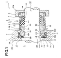
- a mechanical seal device 1 mainly comprises a first seal ring 2, a cup gasket 10 being disposed in the first seal ring 2, a second seal ring 3 oppositely facing the first seal ring 3, a resiliently urging means comprising a bellows 4 and a spring 7 for resiliently supporting the second seal ring 3, and an annular connection ring 5 for joining the second seal ring 3 and the bellows 4.
- the first seal ring 2 has a rectangular section and an annular body.
- a first seal face 2A is located at one end face of the annular body in its axial direction.
- the other end face 2B1 of the first seal ring 2 located opposite to the first seal face 2A and its outer circumferential surface 2B2 define a contact surface 2B whose cross-section is L-shaped.
- the inner diameter surface 2C of the first seal ring 2 is made larger than the outer diameter of a rotary shaft 60. Therefore, a certain clearance is developed between the first seal ring 2 and the rotary shaft 60.
- the first seal ring 2 is made of a hard material.
- the material includes silicon carbide, ceramics, super-hard alloys, carbon materials and so on.
- a housing 50 disposes a step shoulder installation surface 50A for mounting the first seal ring 2.
- the step shoulder installation surface 50A retains a radially extending surface and an axially extending circumferential surface. Therefore the step shoulder installation surface 50A has an annular form.
- the radially extending surface of the step shoulder installation surface 50A has a through hole with an inner diameter surface 51 or a concave inner diameter surface 51 which is not shown in the figure whose axis coincides with the centre axis of the step shoulder installation surface 50A.
- a cup gasket is disposed between the step shoulder installation surface 50A and the first seal ring 2.
- the cup gasket 10 consists of a main body 11 being made of a resilient material such as rubber or resin and a support plate being made of a hard material.
- the main body 11 has a cylindrical cup shape with a hole at its bottom whose half cut-away section is L-shape.
- the main body 11 comprises a holed bottom plate 11A and a cylindrical wall 11B.
- the outer mating surface 11C of the L-shaped main body 11 closely mates with the oppositely facing step shoulder installation surface 50A while the inner mating surface 11D closely mates with the contact surface 2B of the first seal ring 2.
- the axially extending circumferential portion of the outer mating surface 11C retains a plurality of annularly protruding seal portions 12, 12, 12, so that a close contact of the seal portions 12, 12, 12 relative to the step shoulder installation surface 50A provides a sealing function.
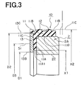
- the diameter X1 of the inner diameter surface 11A1 of the holed bottom plate 11A of the main body 11 is made smaller than the diameter D3 of the inner diameter surface 51 of the housing 50.
- the outer circumference diameter of the cylinder tube portion 11B is deliberately chosen such that the seals 12 provide a sealing contact after an elastic deformation by taking an interference into account. That is, the outer circumference diameter of the cylinder tube portion 11B in an unconstrained form is made slightly larger than the inner diameter X2 of the step shoulder installation surface by the amount of the interference.
- the main body 11 is preferably made of a rubber material such as FKM, NBR, IIR, U, Q, CR and so on.
- the support plate 13 is embedded in the holed bottom plate 11A of the main body 11.
- the support plate 13 has an annular ring form and retains an inner diameter surface 13B and an outer diameter surface 13C.
- the planar form of the support plate 13 is hexagonal, elliptical or provided with slits prepared on the inner circumference or the outer circumference. As shown in Fig. 2, the diameter of the inner diameter surface 13B is D1 while that of the outer diameter surface 13C is D2.
- the side face of the support plate 13 defines a working face 13A which is arranged so as to sustain the process fluid pressure in parallel to the first seal ring 2. Furthermore, the support plate 13 retains axial through holes which are not shown in the figure.
- a material used for the holed bottom plate 11A partially penetrates into the through holes in a vulcanising process of the holed bottom plate 11A and is connected with the opposite side face at the other end of the through holes. This yields a strong connection of the support plate 13 and the holed bottom plate 11A.
- the diameter X1 of the inner diameter surface 11A1 of the main body 11 and the diameter D1 and other dimensions of the inner diameter surface 13B of the support plate 13 are exhibited somewhat small.
- the diameter D1 of the inner diameter surface 13B of the support plate 13 is at least smaller than the diameter D3 of the inner diameter surface 51 of the through hole and larger than the diameter of the inner diameter surface 2C of the first seal ring 2.
- This support plate 13 is a reinforcing element being made of iron, steel, stainless steel, aluminum, resin and so on.
- the second seal ring 3 retains a convex portion which protrudes in an axial direction and defines a second seal face 3A therein forming a close contact with the first seal face 2A of the first seal ring 2.
- its inner diameter surface is fitted over the rotary shaft 60 in a freely slidable manner while its outer diameter surface disposes a plurality of stopper grooves 3B.
- the opposite side of the second seal face 3A of the second seal ring 3 defines a contact face 3C against which one end of the bellows 4 is pressed.
- the cross section of the bellows 4 is partially bent in a Z-shape and its front end is pressed against the contact face 3C.
- the cylindrical portion 4A located in the inner circumferential side of the bellows 4 is fitted over the rotary shaft 60.
- a retainer ring 6 is integrally disposed in the outer circumferential portion of the cylindrical portion 4A wherein an axially extending concave stopper 6A is disposed.
- a joint ring 5 is fitted over the outer diameter surface of the bellows 4 as well as the second seal ring 3 in such a way that the front end of the bellows 4 is pressed toward the contact face 3C of the second seal ring 3 and the second seal ring 3 rotates with the bellows 4 in an integral manner.
- Both ends of the joint ring 5 are bent inwardly such that the front end of the bellows 4 keeps a sealing contact with the contact face 3C of the second seal ring 3.
- a protruding portion 5A disposed in a portion of the joint ring 5 which is located outward relative to the second seal ring 3 engages with the stopper groove 3B of the second seal ring 3.
- the opposite end of the joint ring 5 retains a plurality of protruding plates 5B which are equally spaced in a circumferential direction and engage with the concave stoppers 6A of the retainer ring 6A.
- a spring support ring 8 whose cross section is an L-shape is securely fitted to the shoulder part of the rotary body 60A which is fixed with the rotary shaft 60.
- the second seal face 3A of the second seal ring 3 which is urged by a resiliently urging means 9 comprising attachment components such as bellows 4, spring 7, joint ring 5 and so on, sealingly contacts with the opposing first seal face 2A of the first seal ring 2
- the support plate 13 disposed in the cup gasket 10 supports the cylinder tube portion 11B in an axial direction and induces an elastic deformation of the cylinder tube portion 11B in a radial direction for improving the seal performance of the cylinder tube portion 11B.
- the presence of the support plate 13 enhances the seal performance of the seal portion 12 by avoiding an unwanted deformation of the seal portion 12.
- the support plate 13 disposed in the cup gasket 10 enables the first seal face 2A of the first seal ring 2 to form a sealing contact with the second seal face 3A via the resilient rubber material of the holed bottom plate 11A in which the first seal face 2A approaches the second seal face 3A in a parallel manner. Therefore, an uneven wear of the first seal face 2A can be prevented.
- the overall construction of the mechanical seal device 1 is similar to that of the mechanical seal device 1 shown in Fig. 1.
- a difference between the mechanical seal device 1 of Fig. 1 and that of Fig. 2 is the construction of the cup gasket 10.
- the diameter D1 of the inner diameter surface 13B of the support plate 13 is made smaller than the diameter X1 of the inner diameter surface 11A1 of the main body 11.
- the support plate 13 is partially exposed so as to have a similar surface area to that of the radially extending surface of the holed bottom plate 11A of the main body 11 which is located in the lower pressure side B.
- the diameter D1 of the inner diameter surface 13B of the support plate 13 is made larger than the diameter of the inner diameter surface 2C of the first seal ring 2 as well as smaller than the diameter D3 of the inner diameter surface 51 of the through hole.
- the holed bottom plate 11A is supported by the support plate 13 such that the bottom plate 11A is not directly supported by the step shoulder installation surface 50A.
- This arrangement allows the diameter D3 of the through hole 51 of the housing 50 to be formed large so that it gives more freedom to the design of the housing 50 and the rotary elements disposed within the housing 50.
- the cylinder tube portion 11B retains a couple of the seal portions 12.
- the seal portions 12 being fittingly mated with the step shoulder installation surface 50A are compressed by approximately one third as shown in Fig. 2.
- the diameter D1 of the inner diameter surface 13B of the support plate 13 should preferably be in a range of from the diameter of the inner diameter surface 2C of the first seal ring 2 to the diameter of the inner diameter surface 51 of the through hole.
- This arrangement of the cup gasket 10 can enhance the durability of the cup gasket 10 by securely supporting the holed bottom plate 11A.
- the disposition of the support plate 13 helps to install the mechanical seal device 1 safely even under a case in which the diameter D3 of the inner diameter surface 51 of the through hole is chosen smaller than the diameter X2 of the inner diameter surface 11A1 of the holed bottom plate 11A. This will lead to not only failure prevention but also a compact design of the mechanical seal device 1.
- Fig. 4 shows a cup gasket 10 as a third embodiment of the present seal device.
- the cup gasket 10 has a similar construction to the one shown in Fig. 3. What makes them different is that the support plate 13 is located in the lower pressure side B relative to the holed bottom plate 11A such that the support plate 13 and the holed bottom plate 11A contact with each other.
- the cup gasket 10 allows the support plate 13 to be integrally moulded with the holed bottom plate 11A by means of vulcanising adhesion.
- the support plate 13 can be made of soft aluminum or synthetic resin.
- the diameter of the inner diameter surface 13B of the support plate 13 should preferably be in a range of from the diameter of the inner diameter surface 25 of the first seal ring 2 to the diameter D3 of the inner diameter surface 51 of the through hole.
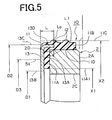
- Fig. 5 shows a cup gasket 10 as a fourth embodiment of the present seal device.
- the support plate 13 retains a cylindrical wall 13D in its outer circumferential portion.
- the length L to the end face La of the cylindrical wall 13D is preferably not to exceed the axial length L1 of the chamfered edge 2D on the outer circumferential surface of the first seal ring 2. Presence of the cylindrical wall 13D simplifies the insertion of the cup gasket 10. Also the cylindrical wall 13D of the support plate 13 supports the cylindrical tube portion 11B providing for the improved seal performance of the cup gasket 10 against the step shoulder installation surface 50A.
- cup gasket 10 enhances the retainability with respect to the first seal face 2A of the first seal ring 2.
- the support plate 13 integrally adhered to the cup gasket which is made of a resilient rubber material ensures that the contact face 2B of the first seal ring 2 not only exhibits a sealing contact relative to the step shoulder installation surface 50A but also is supported in a resilient manner. This enables the first seal face 2A of the first seal ring 2 to form a sealing contact with the opposing second seal face 3A of the second seal ring 3.
- the support plate 13 disposed in the cup gasket 10 provides the first seal ring 2 with a firm support against the process fluid pressure exerted to the seal ring 2.
- the surface 11C of the cup gasket 10 is not affected by the support plate 13, the surface 11C is able to establish a sealing contact with the step shoulder installation surface 50A by fully utilizing its resilient nature.
- the main body 11 of the cup gasket 10 is provided with reinforcement by the support plate 13 integrally disposed in the cup gasket 10 whose inner diameter surface 13B is arranged smaller than the inner diameter surface 51 of the through hole extending through the step shoulder installation surface 50A.
- the cylindrical wall 13D disposed in the support plate 13 makes mating the first seal ring 2 with the cup gasket 10 easy.
- the cylindrical wall 13D also makes it very easy to insert the cup gasket 10 into the step shoulder installation surface 50A without damaging the gasket 10. This ensures that the step shoulder installation surface 50A and the outer circumferential mating surface 11C of the cup gasket 10 are kept in a sealing contact relation.
- the cylindrical wall 13D provides a support for the cylindrical tube portion 11B in an axial direction. Therefore, the seal performance of the cylindrical tube portion 11B is increased. Also a total support for the cup gasket 10 provided by the cylindrical wall 13D and the support face 13A not only enhances the pressure resistance of the cup gasket 10 but also keeps the first seal face 2A of the first seal ring 2 and the opposing second seal face 3A of the second seal ring 3 in parallel with each other for a better seal performance.
Landscapes
- Engineering & Computer Science (AREA)
- General Engineering & Computer Science (AREA)
- Mechanical Engineering (AREA)
- Mechanical Sealing (AREA)
- Gasket Seals (AREA)
Abstract
Description
Claims (3)
- A mechanical seal device (1) for providing a seal between a high pressure process fluid side (A) and a lower pressure side (B) by developing a sealing contact between the two seal faces of a first seal ring (2) mounted on a rotary body (60) and a second seal ring (3) installed in a seal housing (50), said mechanical seal device being characterized by a mating surface (2B) retained by one of said seal rings and being fixedly installed in a step shoulder installation surface (50A); a seal face (2A) located on the opposite side relative to said mating face; a cup gasket (10) disposed between said mating surface of said seal ring and said step shoulder installation surface, said cup gasket being made of a resilient rubber material; and a support plate (13) disposed in said cup gasket in an integral manner, a support face (13A) of said support plate facing opposite relative to and substantially parallel with said mating surface of said seal ring.
- A mechanical seal device (1) as claimed in claim 1, wherein the diameter (D1) of said support plate in said cup gasket is in a range of from the diameter of the inner diameter surface of said seal ring (2) to the diameter (D3) of the inner diameter surface of a through hole extending through said step shoulder installation surface.
- A mechanical seal device (1) as claimed in claim 1 or 2, wherein said support plate retains a cylindrical wall (13D) in the outer circumferential portion of the circular plate and the length (L) of said cylindrical wall does to exceed the axial length of the chamfered corner (2D) located at the outer circumferential edge of said seal ring.
Applications Claiming Priority (2)
| Application Number | Priority Date | Filing Date | Title |
|---|---|---|---|
| JP2002121784A JP4180832B2 (en) | 2002-04-24 | 2002-04-24 | Mechanical seal device |
| JP2002121784 | 2002-04-24 |
Publications (3)
| Publication Number | Publication Date |
|---|---|
| EP1357319A2 true EP1357319A2 (en) | 2003-10-29 |
| EP1357319A3 EP1357319A3 (en) | 2004-03-17 |
| EP1357319B1 EP1357319B1 (en) | 2006-04-12 |
Family
ID=28786775
Family Applications (1)
| Application Number | Title | Priority Date | Filing Date |
|---|---|---|---|
| EP03252592A Expired - Lifetime EP1357319B1 (en) | 2002-04-24 | 2003-04-24 | Mechanical seal device |
Country Status (6)
| Country | Link |
|---|---|
| US (1) | US6962340B2 (en) |
| EP (1) | EP1357319B1 (en) |
| JP (1) | JP4180832B2 (en) |
| KR (1) | KR100949415B1 (en) |
| CN (2) | CN1453488A (en) |
| DE (1) | DE60304504T2 (en) |
Cited By (4)
| Publication number | Priority date | Publication date | Assignee | Title |
|---|---|---|---|---|
| WO2010049077A1 (en) * | 2008-10-31 | 2010-05-06 | Kaco Gmbh + Co. Kg | Axial face seal, in particular for co2 compressors |
| US8128096B2 (en) * | 2006-05-31 | 2012-03-06 | Eagleburgmann Germany Gmbh & Co. Kg | Mechanical seal assembly |
| WO2015122829A1 (en) * | 2014-02-13 | 2015-08-20 | Scania Cv Ab | Face seal |
| US11543033B2 (en) * | 2016-12-29 | 2023-01-03 | Eagle Industry Co., Ltd. | Mechanical seal |
Families Citing this family (29)
| Publication number | Priority date | Publication date | Assignee | Title |
|---|---|---|---|---|
| WO2004068008A2 (en) * | 2003-01-20 | 2004-08-12 | Freudenberg-Nok General Partnership | Heat conducting seal |
| US20060290067A1 (en) * | 2005-06-01 | 2006-12-28 | Freudenberg-Nok General Partnership | Unitized seal with integral spacer |
| KR101331248B1 (en) * | 2005-07-22 | 2013-11-26 | 이글 고오교 가부시키가이샤 | Mechanical seal device |
| US7311307B2 (en) * | 2005-09-29 | 2007-12-25 | Freudenberg-Nok General Partnership | Seal seat assembly with specialized features |
| JP4958445B2 (en) * | 2006-01-26 | 2012-06-20 | サンデン株式会社 | Mechanical seal device for compressor |
| EP2146120A4 (en) * | 2007-04-12 | 2011-11-16 | Eagle Ind Co Ltd | Mechanical seal device |
| SE531210C2 (en) * | 2007-05-07 | 2009-01-20 | Roplan Internat Ab | Mechanical sealing device and pump |
| GB0800509D0 (en) * | 2008-01-11 | 2008-02-20 | Crane John Uk Ltd | Seals |
| CN101910691B (en) * | 2008-05-09 | 2014-02-26 | 伊格尔工业股份有限公司 | Split mechanical seal |
| DE202008009842U1 (en) * | 2008-07-22 | 2008-09-18 | Burgmann Industries Gmbh & Co. Kg | Mechanical seal arrangement with filter element |
| KR100929972B1 (en) * | 2009-06-02 | 2009-12-04 | 조성규 | Mechanical seal |
| JP5839716B2 (en) * | 2010-03-08 | 2016-01-06 | イーグル工業株式会社 | mechanical seal |
| GB201210611D0 (en) * | 2012-06-14 | 2012-08-01 | Aes Eng Ltd | Hygienic seal & system |
| US9297457B2 (en) * | 2013-01-29 | 2016-03-29 | Eagle Industry Co., Ltd. | Sealing device |
| DE102014211982A1 (en) * | 2014-06-23 | 2015-12-24 | Robert Bosch Gmbh | High-pressure fuel pump for a fuel injection system |
| WO2016031411A1 (en) * | 2014-08-26 | 2016-03-03 | イーグル工業株式会社 | Mechanical seal |
| CN105987043A (en) * | 2015-03-05 | 2016-10-05 | 无锡大金高精度冷拔钢管有限公司 | Oil-leakage-preventing oil cylinder with annular boss for marine equipment engineering |
| CN105987042A (en) * | 2015-03-05 | 2016-10-05 | 无锡大金高精度冷拔钢管有限公司 | Oil-leakage-preventing oil cylinder with thrust ring for marine equipment engineering |
| CN107208806B (en) * | 2015-03-05 | 2019-05-28 | 伊格尔工业股份有限公司 | Mechanical seal device, double-end-face seal device and double-end-face mechanical seal device |
| CN105987044A (en) * | 2015-03-05 | 2016-10-05 | 无锡大金高精度冷拔钢管有限公司 | Oil-leakage-preventing oil cylinder with wave spring for marine equipment engineering |
| JP6823602B2 (en) * | 2015-11-09 | 2021-02-03 | イーグル工業株式会社 | mechanical seal |
| KR101632654B1 (en) * | 2016-01-05 | 2016-06-22 | 김정화 | Mechanical seal with rubber shielding assembly |
| CN106000982B (en) * | 2016-07-13 | 2019-02-15 | 苏州长城开发科技有限公司 | The cleaning machine of sealed cleaning cylinder structure and the application structure |
| DE102018126395A1 (en) * | 2018-10-23 | 2020-04-23 | Moog Gmbh | Electrohydrostatic drive with an enlarged operating range |
| EP4206499B1 (en) * | 2020-08-28 | 2025-12-31 | Eagle Industry Co., Ltd. | SEALING DEVICE |
| US20230265927A1 (en) * | 2022-01-20 | 2023-08-24 | John Crane Inc. | Flexible sealing membrane and seal assembly for rotary shaft equipment |
| CN115325163B (en) * | 2022-08-04 | 2025-09-02 | 中国北方车辆研究所 | A floating connection device with bidirectional sealing function |
| KR102546066B1 (en) | 2022-12-07 | 2023-06-28 | 유한회사 부산프로펠러공사 | Method for manufacturing rubber tube for sealing underwater mechanical seal for ship and rubber tube manufactured by the same |
| WO2026058827A1 (en) * | 2024-09-10 | 2026-03-19 | イーグル工業株式会社 | Mechanical seal |
Family Cites Families (6)
| Publication number | Priority date | Publication date | Assignee | Title |
|---|---|---|---|---|
| US4095807A (en) * | 1975-01-03 | 1978-06-20 | Goetzewerke Friedrich Goetze Ag | Slide ring seal |
| JPS6061562U (en) | 1983-10-03 | 1985-04-30 | 大豊工業株式会社 | mechanical seal |
| DE3927589C2 (en) * | 1989-08-22 | 1994-09-29 | Kaco Gmbh Co | Sealing unit |
| DE19846153C1 (en) * | 1998-10-07 | 2000-04-20 | Freudenberg Carl Fa | Mechanical seal |
| DE19914929C2 (en) * | 1999-04-01 | 2001-07-19 | Freudenberg Carl Fa | Mechanical seal |
| DE19914930A1 (en) * | 1999-04-01 | 2000-10-19 | Freudenberg Carl Fa | Mechanical seal |
-
2002
- 2002-04-24 JP JP2002121784A patent/JP4180832B2/en not_active Expired - Lifetime
-
2003
- 2003-04-23 CN CN03123163A patent/CN1453488A/en active Pending
- 2003-04-23 CN CNB2006100840781A patent/CN100540960C/en not_active Expired - Fee Related
- 2003-04-23 KR KR1020030025738A patent/KR100949415B1/en not_active Expired - Fee Related
- 2003-04-23 US US10/420,718 patent/US6962340B2/en not_active Expired - Lifetime
- 2003-04-24 DE DE60304504T patent/DE60304504T2/en not_active Expired - Lifetime
- 2003-04-24 EP EP03252592A patent/EP1357319B1/en not_active Expired - Lifetime
Cited By (5)
| Publication number | Priority date | Publication date | Assignee | Title |
|---|---|---|---|---|
| US8128096B2 (en) * | 2006-05-31 | 2012-03-06 | Eagleburgmann Germany Gmbh & Co. Kg | Mechanical seal assembly |
| WO2010049077A1 (en) * | 2008-10-31 | 2010-05-06 | Kaco Gmbh + Co. Kg | Axial face seal, in particular for co2 compressors |
| WO2015122829A1 (en) * | 2014-02-13 | 2015-08-20 | Scania Cv Ab | Face seal |
| EP3105478A4 (en) * | 2014-02-13 | 2018-01-03 | Scania CV AB | Face seal |
| US11543033B2 (en) * | 2016-12-29 | 2023-01-03 | Eagle Industry Co., Ltd. | Mechanical seal |
Also Published As
| Publication number | Publication date |
|---|---|
| KR20030084705A (en) | 2003-11-01 |
| JP4180832B2 (en) | 2008-11-12 |
| JP2003314702A (en) | 2003-11-06 |
| EP1357319A3 (en) | 2004-03-17 |
| CN1862063A (en) | 2006-11-15 |
| CN1453488A (en) | 2003-11-05 |
| US6962340B2 (en) | 2005-11-08 |
| DE60304504T2 (en) | 2006-12-07 |
| DE60304504D1 (en) | 2006-05-24 |
| HK1097031A1 (en) | 2007-06-15 |
| US20040036228A1 (en) | 2004-02-26 |
| KR100949415B1 (en) | 2010-03-24 |
| EP1357319B1 (en) | 2006-04-12 |
| CN100540960C (en) | 2009-09-16 |
Similar Documents
| Publication | Publication Date | Title |
|---|---|---|
| EP1357319B1 (en) | Mechanical seal device | |
| US7296800B2 (en) | Seal device | |
| US6565096B2 (en) | Lip type seal | |
| EP1577591B1 (en) | Mechanical seal device | |
| CN101553393B (en) | Sealing arrangement and link of a chain with the sealing arrangement | |
| CN1454301A (en) | Improved mechanical face seal | |
| US7648144B2 (en) | Sealing device | |
| US7093836B2 (en) | Seal device | |
| CN109073086B (en) | Dust-proof sealing part | |
| AU700934B2 (en) | Liquid pump seal | |
| CN101389887A (en) | Elastomer Spring Mechanical Seals | |
| US6338489B1 (en) | Mechanical seal | |
| US6142476A (en) | Mechanical seal | |
| US20070241511A1 (en) | Compact mechanical seal | |
| HK1057776A (en) | Mechanical seal device | |
| US20050077684A1 (en) | Mechanical seal without elastomers | |
| EP1739332A1 (en) | Radial lip seal | |
| CN216478928U (en) | Mechanical sealing device for oil pump | |
| GB2083873A (en) | Sealing rings | |
| CA2498633C (en) | Element that defines a gap and is to be mounted on a shaft | |
| GB2378487A (en) | A seal assembly for use in high speed, high pressure applications | |
| JP2009085274A (en) | Piston seal for automatic transmission | |
| HK1097031B (en) | Mechanical seal device | |
| JPH0534362U (en) | Sealing device | |
| JPS6217649Y2 (en) |
Legal Events
| Date | Code | Title | Description |
|---|---|---|---|
| PUAI | Public reference made under article 153(3) epc to a published international application that has entered the european phase |
Free format text: ORIGINAL CODE: 0009012 |
|
| AK | Designated contracting states |
Kind code of ref document: A2 Designated state(s): AT BE BG CH CY CZ DE DK EE ES FI FR GB GR HU IE IT LI LU MC NL PT RO SE SI SK TR |
|
| AX | Request for extension of the european patent |
Extension state: AL LT LV MK |
|
| PUAL | Search report despatched |
Free format text: ORIGINAL CODE: 0009013 |
|
| AK | Designated contracting states |
Kind code of ref document: A3 Designated state(s): AT BE BG CH CY CZ DE DK EE ES FI FR GB GR HU IE IT LI LU MC NL PT RO SE SI SK TR |
|
| AX | Request for extension of the european patent |
Extension state: AL LT LV MK |
|
| RIC1 | Information provided on ipc code assigned before grant |
Ipc: 7F 16J 15/34 A Ipc: 7F 16J 15/38 B |
|
| 17P | Request for examination filed |
Effective date: 20040904 |
|
| AKX | Designation fees paid |
Designated state(s): DE FR |
|
| 17Q | First examination report despatched |
Effective date: 20041201 |
|
| GRAP | Despatch of communication of intention to grant a patent |
Free format text: ORIGINAL CODE: EPIDOSNIGR1 |
|
| GRAS | Grant fee paid |
Free format text: ORIGINAL CODE: EPIDOSNIGR3 |
|
| GRAA | (expected) grant |
Free format text: ORIGINAL CODE: 0009210 |
|
| AK | Designated contracting states |
Kind code of ref document: B1 Designated state(s): DE FR |
|
| REF | Corresponds to: |
Ref document number: 60304504 Country of ref document: DE Date of ref document: 20060524 Kind code of ref document: P |
|
| ET | Fr: translation filed | ||
| PLBE | No opposition filed within time limit |
Free format text: ORIGINAL CODE: 0009261 |
|
| STAA | Information on the status of an ep patent application or granted ep patent |
Free format text: STATUS: NO OPPOSITION FILED WITHIN TIME LIMIT |
|
| 26N | No opposition filed |
Effective date: 20070115 |
|
| REG | Reference to a national code |
Ref country code: HK Ref legal event code: WD Ref document number: 1057776 Country of ref document: HK |
|
| REG | Reference to a national code |
Ref country code: FR Ref legal event code: PLFP Year of fee payment: 14 |
|
| REG | Reference to a national code |
Ref country code: FR Ref legal event code: PLFP Year of fee payment: 15 |
|
| REG | Reference to a national code |
Ref country code: FR Ref legal event code: PLFP Year of fee payment: 16 |
|
| PGFP | Annual fee paid to national office [announced via postgrant information from national office to epo] |
Ref country code: FR Payment date: 20180315 Year of fee payment: 16 |
|
| PGFP | Annual fee paid to national office [announced via postgrant information from national office to epo] |
Ref country code: DE Payment date: 20180410 Year of fee payment: 16 |
|
| REG | Reference to a national code |
Ref country code: DE Ref legal event code: R119 Ref document number: 60304504 Country of ref document: DE |
|
| PG25 | Lapsed in a contracting state [announced via postgrant information from national office to epo] |
Ref country code: DE Free format text: LAPSE BECAUSE OF NON-PAYMENT OF DUE FEES Effective date: 20191101 |
|
| PG25 | Lapsed in a contracting state [announced via postgrant information from national office to epo] |
Ref country code: FR Free format text: LAPSE BECAUSE OF NON-PAYMENT OF DUE FEES Effective date: 20190430 |