EP1357296A1 - Blower, and outdoor unit for air conditioner - Google Patents
Blower, and outdoor unit for air conditioner Download PDFInfo
- Publication number
- EP1357296A1 EP1357296A1 EP01272799A EP01272799A EP1357296A1 EP 1357296 A1 EP1357296 A1 EP 1357296A1 EP 01272799 A EP01272799 A EP 01272799A EP 01272799 A EP01272799 A EP 01272799A EP 1357296 A1 EP1357296 A1 EP 1357296A1
- Authority
- EP
- European Patent Office
- Prior art keywords
- blade
- bell mouth
- blowoff
- outer peripheral
- circular arc
- Prior art date
- Legal status (The legal status is an assumption and is not a legal conclusion. Google has not performed a legal analysis and makes no representation as to the accuracy of the status listed.)
- Granted
Links
Images







Classifications
-
- F—MECHANICAL ENGINEERING; LIGHTING; HEATING; WEAPONS; BLASTING
- F04—POSITIVE - DISPLACEMENT MACHINES FOR LIQUIDS; PUMPS FOR LIQUIDS OR ELASTIC FLUIDS
- F04D—NON-POSITIVE-DISPLACEMENT PUMPS
- F04D29/00—Details, component parts, or accessories
- F04D29/26—Rotors specially for elastic fluids
- F04D29/32—Rotors specially for elastic fluids for axial flow pumps
- F04D29/38—Blades
- F04D29/384—Blades characterised by form
-
- F—MECHANICAL ENGINEERING; LIGHTING; HEATING; WEAPONS; BLASTING
- F04—POSITIVE - DISPLACEMENT MACHINES FOR LIQUIDS; PUMPS FOR LIQUIDS OR ELASTIC FLUIDS
- F04D—NON-POSITIVE-DISPLACEMENT PUMPS
- F04D29/00—Details, component parts, or accessories
- F04D29/40—Casings; Connections of working fluid
- F04D29/52—Casings; Connections of working fluid for axial pumps
- F04D29/54—Fluid-guiding means, e.g. diffusers
- F04D29/541—Specially adapted for elastic fluid pumps
- F04D29/545—Ducts
Definitions
- the present invention relates to a blower device and an outdoor unit for air conditioner.
- an outdoor unit for air conditioner is, as shown in Fig. 1 through Fig. 3, constituted such that a blower device 3 composed of a propeller fan 4 having a plurality of (e.g. three) blades 13, 13, 13 formed on the outer periphery of a hub 14 that functions as the center of rotation, a bell mouth 5 disposed on the outer radial side of the propeller fan 4 for separating a suction area X and a blowoff area Y, and a fan guard 6 disposed on the blowoff side of the propeller fan 4, is disposed downstream from a heat exchanger 2 in a casing 1. Inside of the casing 1 is divided into a heat exchange chamber 8 and a machine chamber 9 by a dividing board 7.
- a heat exchanger 2 having an L-shaped cross section that faces air suction ports 10, 10 formed on the back side and on one lateral side of the casing 1, and a blower device 3 disposed downstream from the heat exchanger 2, whereas in the machine chamber 9, a compressor 11 is disposed.
- Reference numeral 12 denotes a fan motor.
- equipment such as ventilating fans and air cleaners may also adopt the similarly constituted blower device 3 (i.e., a blower device composed of a propeller fan 4, a bell mouth 5 disposed outside of the propeller fan 4 for separating a suction area and a blowoff area, and a fan guard 6 disposed on the blowoff side of the propeller fan).
- blower device 3 i.e., a blower device composed of a propeller fan 4, a bell mouth 5 disposed outside of the propeller fan 4 for separating a suction area and a blowoff area, and a fan guard 6 disposed on the blowoff side of the propeller fan.
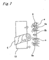
- FIG. 7 airflows expressed by chain lines in Fig. 7 occur in a position symmetrical to the position of airflows expressed by solid lines (i.e., a position opposite to the center of rotation), though they are shown on the same cross section for convenience of description.
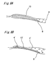
- some fans have a blade 13 having a thick airfoil shape as typified by airfoil wings.
- a single-unit fan in the state without a casing surrounding the fan and a fan guard on the blowoff side
- a thin plate-shaped blade 13' as shown in Fig.
- noise i.e. operation noise
- a blower device comprising: a propeller fan 4 having a plurality of blades 13, 13 ... in a thick airfoil shape as typified by airfoil wings formed on an outer periphery of a hub 14 that functions as a center of rotation; a bell mouth 5 disposed on an outer radial side of the propeller fan 4 for separating a suction area X and a blowoff area Y; and a fan guard 6 disposed on a blowoff side of the propeller fan 4,
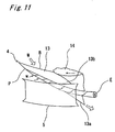
- the above structure makes it possible to restrain growth of a leakage flow (i.e., a wing tip vortex E) from the positive pressure surface 13a to the negative pressure surface 13b of the blade 13 in a part of the outer peripheral portion P of the blade 13 not surrounded by the bell mouth 5 while maintaining a suction flow from the outer peripheral portion P of the blade 13.
- a leakage flow i.e., a wing tip vortex E
- This makes it possible to reduce noise generated from the fan guard 6 by collision of the wing tip vortex E with the fan guard 6 on the blowoff side, resulting in forming remarkable contribution to decline of operation noise.
- blowing noise of the present invention i.e., the blower device incorporating a propeller fan having a plurality of thick airfoil-shaped blades as typified by airfoil wings
- a dotted line in Fig. 13 expresses a measurement result of blowing noise generated by a blower device incorporating a propeller fan having a plurality of thin plate-shaped blades for comparison with the present invention.
- a leakage flow i.e., a wing tip vortex E
- a growth area of the wing tip vortex E i.e., a part of the outer peripheral portion P of the blade 3 not surrounded by the cylinder portion 5c of the bell mouth
- a growth area of the wing tip vortex E becomes too large, making an effect of the cylinder portion 5c for restraining growth of the wing tip vortex E insufficient, thereby increasing interference noise by the wing tip vortex E and the fan guard 6.
- blowing noise of the present invention i.e., the blower device incorporating a propeller fan having a plurality of thick airfoil-shaped blades as typified by airfoil wings
- H 2 /H 0 the blower device incorporating a propeller fan having a plurality of thick airfoil-shaped blades as typified by airfoil wings
- a start position of a circular arc of the blowoff side circular arc portion 5b in the bell mouth 5 is approximately identical to a position of a trailing edge portion B of each of the blade 13. Therefore, a trailing edge B of the blade 3 is away from the fan guard 6 by a size equivalent to the radius of the blowoff side circular arc portion 5b of the bell mouth 5, so that blowoff velocity is reduced and an airflow W blown from the trailing edge B of the blade 3 is smoothly spread toward outside without being separated from the blowoff side circular arc portion 5b of the bell mouth 5, which enables reduction of velocity without causing turbulence till the airflow reaches the fan guard 6, thereby implementing reduction of interference noise with the fan guard 6.
- an outdoor unit for air conditioner comprising the blower device 3 and a heat exchanger 2 disposed on a suction side of the blower device 3.
- This outdoor unit for air conditioner can reduce operation noise.
- the blower device 3 which is for use in an outdoor unit for air conditioner shown in Fig. 1 to Fig. 3 like the device described in the technical field chapter, is composed of a propeller fan 4 having a plurality of (e.g. three) blades 13, 13, 13 formed on the outer periphery of a cylinder-shaped hub 14 that functions as the center of rotation, a bell mouth 5 disposed outside of the propeller fan 4 for separating a suction area X and a blowoff area Y, and a fan guard 6 disposed on the blowoff side of the propeller fan 4.
- a propeller fan 4 having a plurality of (e.g. three) blades 13, 13, 13 formed on the outer periphery of a cylinder-shaped hub 14 that functions as the center of rotation
- a bell mouth 5 disposed outside of the propeller fan 4 for separating a suction area X and a blowoff area Y
- a fan guard 6 disposed on the blowoff side of the propeller fan 4.
- the outdoor unit for air conditioner is constituted such that the inside of a hexahedron-shaped casing 1 is divided into a heat exchange chamber 8 and a machine chamber 9 by a dividing board 7.
- a heat exchanger 2 having an L-shaped cross section that faces air suction ports 10, 10 formed on the back side and on one lateral side of the casing 1, and a blower device 3 disposed downstream from the heat exchanger 2, whereas in the machine chamber 9, a compressor 11 is disposed.
- Reference numeral 12 denotes a fan motor.
- the airfoil wing having a special form includes those shown in Figs. 9B to 9D.
- the airfoil wing having a special form shown in Fig. 9B is in the shape of an airfoil which has a swelling portion in a leading edge F, and whose wing thickness is sharply reduced from the swelling portion and then gradually reduced toward a trailing edge B.
- the airfoil wing having a special form shown in Fig. 9C is in the shape of an airfoil which has a circular arc portion in the leading edge F and whose wing thickness is gradually reduced toward the trailing edge B.
- 9D is in the shape of an airfoil which has a trailing edge F having the shape of a circular arc and whose wing thickness is once increased toward the trailing edge B, then sharply reduced, and gradually reduced toward the trailing edge B.
- These airfoil wings having a special form have capability similar to the airfoil wing.
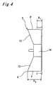
- the bell mouth 5 is composed of a suction side circular arc portion 5a positioned on a suction side, a blowoff side circular arc 5b positioned on a blowoff side, and a cylinder portion 5c positioned in between the blowoff side circular arc portion 5b and the suction side circular arc portion 5a, and the trailing edge B of the propeller fan 4 is disposed in the position corresponding to the outer edge of the cylinder portion 5c of the bell mouth 5 (in other words, a start position of the circular arc of the blowoff side circular arc portion 5b in the bell mouth 5 is approximately identical to the position of the trailing edge portion B of the blade 13).
- a leakage flow i.e., a wing tip vortex E
- the above setting makes it possible to restrain growth of a leakage flow (i.e., a wing tip vortex E) from the positive pressure surface 13a to the negative pressure surface 13b of the blade 13 in a part of the outer peripheral portion P of the blade 13 not surrounded by the bell mouth 5 while maintaining a suction flow from the outer peripheral portion P of the blade 13.
- a leakage flow i.e., a wing tip vortex E
- the wing tip vortex E is downsized. Consequently, noise generated from the fan guard 6 by collision of the wing tip vortex E with the fan guard 6 on the blowoff side may be reduced, resulting in formation of remarkable contribution to decline of operation noise.
- blowing noise of the present invention i.e., the blower device incorporating a propeller fan having a plurality of thick airfoil-shaped blades as typified by airfoil wings
- a dotted line in Fig. 13 expresses a measurement result of blowing noise generated by a blower device incorporating a propeller fan having a plurality of thin plate-shaped blades for comparison with the present invention.
- the above setting makes it possible to restrain growth of a leakage flow (i.e., a wing tip vortex E) from the positive pressure surface 13a to the negative pressure surface 13b of the blade 13 by the presence of the cylinder portion 5c of the bell mouth 5.
- a leakage flow i.e., a wing tip vortex E
- a growth area of the wing tip vortex E i.e., a part of the outer peripheral portion P of the blade 3 not surrounded by the cylinder portion 5c of the bell mouth
- a growth area of the wing tip vortex E becomes too large, making an effect of the cylinder portion 5c for restraining growth of the wing tip vortex E insufficient, thereby increasing interference noise by the wing tip vortex E and the fan guard 6.
- blowing noise of the present invention i.e., the blower device incorporating a propeller fan having a plurality of thick airfoil-shaped blades as typified by airfoil wings
- H 2 /H 0 the blower device incorporating a propeller fan having a plurality of thick airfoil-shaped blades as typified by airfoil wings
- the propeller fan 4 equipped with a bell mouth for use in the blower device 3 as the present invention underwent a single-unit test under the following procedure.
- a fan motor 12 was secured on a supporting base 15 to set the propeller fan 4 equipped with a bell mouth in a specified position, and a highly directional microphone 16 was set on the suction side of the propeller fan 4 for collecting operation noise by operating the propeller fan 4. Then, the test was carried out with a value of H 3 , a height of the bell mouth 5 and a value of H 0 , an axis directional height of the blade 13 being changed, and a result shown in Fig. 16 was obtained.
- blowing noise can be reduced by decreasing the height H 3 of the bell mouth 5 for narrowing an area of the blade 13 surrounded by the bell mouth 5 (i.e., to decrease H 3 /H 0 ) and increasing a suction amount by the blade 13 from the outer periphery.
- Decrease of the height H 3 of the bell mouth 5 increases an area for a wing tip vortex to occur and develop and locally enlarges turbulence in the outer peripheral portion of the blade 13, so that blowing noise is considered to increase, though in actuality the blowing noise decreases as shown in Fig. 16.
- a start position of the circular arc of the blowoff side circular arc portion 5b in the bell mouth 5 is set approximately identical to a position of the trailing edge B of each of the blade 13. Consequently, a trailing edge B of the blade 3 is away from the fan guard 6 by a size equivalent to the radius of the blowoff side circular arc portion 5b of the bell mouth 5, so that blowoff velocity is reduced and an airflow W blown from the trailing edge B of the blade 3 is smoothly spread toward outside without being separated from the blowoff side circular arc portion 5b of the bell mouth 5, which enables reduction of velocity without causing turbulence till the airflow reaches the fan guard 6, thereby implementing reduction of interference noise with the fan guard 6.
- the blowoff airflow W becomes a rapid enlarged flow to generate turbulence e. If the blowoff side circular arc portion of the bell mouth 5 is removed and the fan guard 6 is set closer to the trailing edge B of the blade 13 as shown in Fig. 17B, interference noise by the blowoff airflow W and the fan guard 6 becomes large. If a taper-shaped expanded portion 5d is formed from upstream to the trailing edge B of the blade 3 on the blowoff side of the bell mouth 5 as shown in Fig.
- turbulence e is generated in a space between the outer periphery of the blade 13 and the taper-shaped expanded portion 5d, which increases interference noise with the fan guard 6. Because of the above reasons, a start position of the circular arc of the blowoff side circular arc portion 5b in the bell mouth 5 is preferably set approximately identical to a position of the trailing edge B of each of the blade 13.
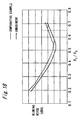
- blowing noises in the case where the blowoff side circular arc portion of the bell mouth 5 is removed (hereinbelow referred to as a reference example) and in the case where a start position of the circular arc of the blowoff side circular arc portion 5b in the bell mouth 5 is set approximately identical to a position of the trailing edge B of each of the blade 13 (hereinbelow referred to as a present embodiment) were measured with a value of H 1 /H 0 varied, and a result shown in Fig. 18 was obtained. This also indicates that device of the present embodiment contributes to reduction of noise.
- the present invention is applied to a blower device enabling reduction of operation noise by restraining generation of a wing tip vortex on a propeller fan, and to an outdoor unit for air conditioner using the same.
Landscapes
- Engineering & Computer Science (AREA)
- Mechanical Engineering (AREA)
- General Engineering & Computer Science (AREA)
- Structures Of Non-Positive Displacement Pumps (AREA)
Abstract
Description
Claims (4)
- A blower device comprising: a propeller fan (4) having a plurality of blades (13), (13) ... in a thick airfoil shape as typified by airfoil wings formed on an outer periphery of a hub (14) that functions as a center of rotation; a bell mouth (5) disposed on an outer radial side of the propeller fan (4) for separating a suction area (X) and a blowoff area (Y); and a fan guard (6) disposed on a blowoff side of the propeller fan (4),
the bell mouth (5) being composed of a suction side circular arc portion (5a) positioned on a suction side, a blowoff side circular arc (5b) positioned on a blowoff side, and a cylinder portion (5c) positioned in between the blowoff side circular arc (5b) and the suction side circular arc portion (5a), a ratio of H1/H0 being set in a range of H1/H0 = 0.40 to 0.65 where H1 denotes a height of a portion of an axis directional height of the bell mouth (5) that is overlapped with an outer peripheral portion (P) of each of the blade (13), while H0 denotes an axis directional height of the outer peripheral portion (P) of each of the blade (13). - The blower device as defined in Claim 1, wherein
the cylinder portion (5c) of the bell mouth (5) is overlapped with the outer peripheral portion (P) of each of the blade (13), and a ratio of H2/H0 is set in a range of H2/H0 = 0.25 to 0.50 where H2 denotes an axis directional height of the cylinder portion (5c). - The blower device as defined in Claim 1 or 2, wherein
a start position of a circular arc of the blowoff side circular arc portion (5b) in the bell mouth (5) is approximately identical to a position of a trailing edge portion (B) of each of the blade (13). - An outdoor unit for air conditioner comprising the blower device (3) as defined in any one of Claim 1 to Claim 3 and a heat exchanger (2) disposed on a suction side of the blower device (3).
Applications Claiming Priority (3)
| Application Number | Priority Date | Filing Date | Title |
|---|---|---|---|
| JP2000400530 | 2000-12-28 | ||
| JP2000400530 | 2000-12-28 | ||
| PCT/JP2001/010599 WO2002053919A1 (en) | 2000-12-28 | 2001-12-05 | Blower, and outdoor unit for air conditioner |
Publications (3)
| Publication Number | Publication Date |
|---|---|
| EP1357296A1 true EP1357296A1 (en) | 2003-10-29 |
| EP1357296A4 EP1357296A4 (en) | 2004-01-14 |
| EP1357296B1 EP1357296B1 (en) | 2006-06-28 |
Family
ID=18865110
Family Applications (1)
| Application Number | Title | Priority Date | Filing Date |
|---|---|---|---|
| EP01272799A Expired - Lifetime EP1357296B1 (en) | 2000-12-28 | 2001-12-05 | Blower, and outdoor unit for air conditioner |
Country Status (7)
| Country | Link |
|---|---|
| EP (1) | EP1357296B1 (en) |
| CN (1) | CN1210503C (en) |
| AU (1) | AU2002221045B2 (en) |
| DE (1) | DE60121222T2 (en) |
| ES (1) | ES2266106T3 (en) |
| TW (1) | TW517825U (en) |
| WO (1) | WO2002053919A1 (en) |
Cited By (15)
| Publication number | Priority date | Publication date | Assignee | Title |
|---|---|---|---|---|
| EP1610068A4 (en) * | 2003-03-31 | 2007-11-21 | Toshiba Carrier Corp | EXTERNAL UNIT FOR AIR CONDITIONING |
| US9752789B2 (en) | 2012-03-06 | 2017-09-05 | Dyson Technology Limited | Humidifying apparatus |
| US9797612B2 (en) | 2013-01-29 | 2017-10-24 | Dyson Technology Limited | Fan assembly |
| US9797613B2 (en) | 2012-03-06 | 2017-10-24 | Dyson Technology Limited | Humidifying apparatus |
| US9822778B2 (en) | 2012-04-19 | 2017-11-21 | Dyson Technology Limited | Fan assembly |
| US9903602B2 (en) | 2014-07-29 | 2018-02-27 | Dyson Technology Limited | Humidifying apparatus |
| US9982677B2 (en) | 2014-07-29 | 2018-05-29 | Dyson Technology Limited | Fan assembly |
| US10094581B2 (en) | 2011-07-27 | 2018-10-09 | Dyson Technology Limited | Fan assembly |
| US10145583B2 (en) | 2012-04-04 | 2018-12-04 | Dyson Technology Limited | Heating apparatus |
| US10221860B2 (en) | 2009-03-04 | 2019-03-05 | Dyson Technology Limited | Fan assembly |
| US10344773B2 (en) | 2010-08-06 | 2019-07-09 | Dyson Technology Limited | Fan assembly |
| US10408478B2 (en) | 2012-03-06 | 2019-09-10 | Dyson Technology Limited | Humidifying apparatus |
| US10465928B2 (en) | 2012-03-06 | 2019-11-05 | Dyson Technology Limited | Humidifying apparatus |
| US10612565B2 (en) | 2013-01-29 | 2020-04-07 | Dyson Technology Limited | Fan assembly |
| US20220178382A1 (en) * | 2019-08-26 | 2022-06-09 | Daikin Industries, Ltd. | Blower and heat pump unit |
Families Citing this family (42)
| Publication number | Priority date | Publication date | Assignee | Title |
|---|---|---|---|---|
| GB2452593A (en) | 2007-09-04 | 2009-03-11 | Dyson Technology Ltd | A fan |
| JP4400686B2 (en) | 2008-01-07 | 2010-01-20 | ダイキン工業株式会社 | Propeller fan |
| JP4823294B2 (en) | 2008-11-04 | 2011-11-24 | 三菱電機株式会社 | Blower and heat pump device using this blower |
| PT2276933E (en) | 2009-03-04 | 2011-08-17 | Dyson Technology Ltd | A fan |
| EP2414738B1 (en) | 2009-03-04 | 2013-10-09 | Dyson Technology Limited | Humidifying apparatus |
| CN101696696B (en) * | 2009-10-27 | 2013-05-15 | 广东志高空调有限公司 | Fan of outdoor unit of air conditioner |
| GB0919473D0 (en) | 2009-11-06 | 2009-12-23 | Dyson Technology Ltd | A fan |
| JP5322900B2 (en) * | 2009-11-27 | 2013-10-23 | 三洋電機株式会社 | Bell mouth structure of blower |
| DK2990663T3 (en) | 2010-05-27 | 2017-10-02 | Dyson Technology Ltd | DEVICE FOR Blowing air by means of narrow slit nozzle |
| GB2482548A (en) | 2010-08-06 | 2012-02-08 | Dyson Technology Ltd | A fan assembly with a heater |
| JP5588565B2 (en) | 2010-10-13 | 2014-09-10 | ダイソン テクノロジー リミテッド | Blower assembly |
| GB2484670B (en) | 2010-10-18 | 2018-04-25 | Dyson Technology Ltd | A fan assembly |
| ES2619373T3 (en) | 2010-10-18 | 2017-06-26 | Dyson Technology Limited | Fan set |
| WO2012059730A1 (en) | 2010-11-02 | 2012-05-10 | Dyson Technology Limited | A fan assembly |
| CN103649549B (en) * | 2011-07-13 | 2016-07-06 | 松下电器产业株式会社 | The off-premises station of axial flow fan and air conditioner |
| AU2012288597B2 (en) | 2011-07-27 | 2015-04-09 | Dyson Technology Limited | A fan assembly |
| GB201119500D0 (en) | 2011-11-11 | 2011-12-21 | Dyson Technology Ltd | A fan assembly |
| GB2496877B (en) | 2011-11-24 | 2014-05-07 | Dyson Technology Ltd | A fan assembly |
| GB2499044B (en) | 2012-02-06 | 2014-03-19 | Dyson Technology Ltd | A fan |
| GB2499042A (en) | 2012-02-06 | 2013-08-07 | Dyson Technology Ltd | A nozzle for a fan assembly |
| GB2499041A (en) | 2012-02-06 | 2013-08-07 | Dyson Technology Ltd | Bladeless fan including an ionizer |
| GB2500010B (en) | 2012-03-06 | 2016-08-24 | Dyson Technology Ltd | A humidifying apparatus |
| EP2823183A1 (en) | 2012-03-06 | 2015-01-14 | Dyson Technology Limited | A fan assembly |
| AU350181S (en) | 2013-01-18 | 2013-08-15 | Dyson Technology Ltd | Humidifier or fan |
| AU350140S (en) | 2013-01-18 | 2013-08-13 | Dyson Technology Ltd | Humidifier or fan |
| AU350179S (en) | 2013-01-18 | 2013-08-15 | Dyson Technology Ltd | Humidifier or fan |
| BR302013003358S1 (en) | 2013-01-18 | 2014-11-25 | Dyson Technology Ltd | CONFIGURATION APPLIED ON HUMIDIFIER |
| CA152657S (en) | 2013-03-07 | 2014-05-20 | Dyson Technology Ltd | Fan |
| USD729372S1 (en) | 2013-03-07 | 2015-05-12 | Dyson Technology Limited | Fan |
| BR302013004394S1 (en) | 2013-03-07 | 2014-12-02 | Dyson Technology Ltd | CONFIGURATION APPLIED TO FAN |
| CA152658S (en) | 2013-03-07 | 2014-05-20 | Dyson Technology Ltd | Fan |
| CA152655S (en) | 2013-03-07 | 2014-05-20 | Dyson Technology Ltd | Fan |
| CA152656S (en) | 2013-03-07 | 2014-05-20 | Dyson Technology Ltd | Fan |
| CA154722S (en) | 2013-08-01 | 2015-02-16 | Dyson Technology Ltd | Fan |
| CA154723S (en) | 2013-08-01 | 2015-02-16 | Dyson Technology Ltd | Fan |
| TWD172707S (en) | 2013-08-01 | 2015-12-21 | 戴森科技有限公司 | A fan |
| GB2518638B (en) | 2013-09-26 | 2016-10-12 | Dyson Technology Ltd | Humidifying apparatus |
| GB2528709B (en) | 2014-07-29 | 2017-02-08 | Dyson Technology Ltd | Humidifying apparatus |
| CN107178525B (en) * | 2017-06-23 | 2019-02-15 | 广东美的制冷设备有限公司 | Wind wheel component and refrigeration equipment with it |
| KR102500528B1 (en) | 2018-03-22 | 2023-02-15 | 엘지전자 주식회사 | Outdoor unit of air conditioner |
| EP3591238A1 (en) * | 2018-07-05 | 2020-01-08 | Xylem Europe GmbH | Axial flow fan and fan guard for a motor cooling assembly |
| WO2022137388A1 (en) * | 2020-12-23 | 2022-06-30 | 三菱電機株式会社 | Blower |
Family Cites Families (7)
| Publication number | Priority date | Publication date | Assignee | Title |
|---|---|---|---|---|
| US3937192A (en) * | 1974-09-03 | 1976-02-10 | General Motors Corporation | Ejector fan shroud arrangement |
| JPH03267600A (en) * | 1990-03-19 | 1991-11-28 | Matsushita Refrig Co Ltd | Axial blower |
| JPH04353300A (en) * | 1991-05-30 | 1992-12-08 | Matsushita Refrig Co Ltd | Blower |
| US5183382A (en) * | 1991-09-03 | 1993-02-02 | Caterpillar Inc. | Low noise rotating fan and shroud assembly |
| JPH05133398A (en) * | 1991-11-12 | 1993-05-28 | Matsushita Electric Ind Co Ltd | Blower |
| JPH11337126A (en) * | 1998-05-29 | 1999-12-10 | Matsushita Refrig Co Ltd | Outdoor unit of air conditioner |
| JP3632119B2 (en) * | 1999-04-21 | 2005-03-23 | ダイキン工業株式会社 | Mixed flow fan |
-
2001
- 2001-12-05 AU AU2002221045A patent/AU2002221045B2/en not_active Ceased
- 2001-12-05 EP EP01272799A patent/EP1357296B1/en not_active Expired - Lifetime
- 2001-12-05 CN CN 01805718 patent/CN1210503C/en not_active Expired - Fee Related
- 2001-12-05 WO PCT/JP2001/010599 patent/WO2002053919A1/en not_active Ceased
- 2001-12-05 DE DE60121222T patent/DE60121222T2/en not_active Expired - Lifetime
- 2001-12-05 ES ES01272799T patent/ES2266106T3/en not_active Expired - Lifetime
- 2001-12-06 TW TW91213946U patent/TW517825U/en not_active IP Right Cessation
Cited By (17)
| Publication number | Priority date | Publication date | Assignee | Title |
|---|---|---|---|---|
| EP1610068A4 (en) * | 2003-03-31 | 2007-11-21 | Toshiba Carrier Corp | EXTERNAL UNIT FOR AIR CONDITIONING |
| US10221860B2 (en) | 2009-03-04 | 2019-03-05 | Dyson Technology Limited | Fan assembly |
| US10344773B2 (en) | 2010-08-06 | 2019-07-09 | Dyson Technology Limited | Fan assembly |
| US10094581B2 (en) | 2011-07-27 | 2018-10-09 | Dyson Technology Limited | Fan assembly |
| US9752789B2 (en) | 2012-03-06 | 2017-09-05 | Dyson Technology Limited | Humidifying apparatus |
| US10563875B2 (en) | 2012-03-06 | 2020-02-18 | Dyson Technology Limited | Humidifying apparatus |
| US9797613B2 (en) | 2012-03-06 | 2017-10-24 | Dyson Technology Limited | Humidifying apparatus |
| US10465928B2 (en) | 2012-03-06 | 2019-11-05 | Dyson Technology Limited | Humidifying apparatus |
| US10408478B2 (en) | 2012-03-06 | 2019-09-10 | Dyson Technology Limited | Humidifying apparatus |
| US10145583B2 (en) | 2012-04-04 | 2018-12-04 | Dyson Technology Limited | Heating apparatus |
| US9822778B2 (en) | 2012-04-19 | 2017-11-21 | Dyson Technology Limited | Fan assembly |
| US9797612B2 (en) | 2013-01-29 | 2017-10-24 | Dyson Technology Limited | Fan assembly |
| US10612565B2 (en) | 2013-01-29 | 2020-04-07 | Dyson Technology Limited | Fan assembly |
| US9982677B2 (en) | 2014-07-29 | 2018-05-29 | Dyson Technology Limited | Fan assembly |
| US9903602B2 (en) | 2014-07-29 | 2018-02-27 | Dyson Technology Limited | Humidifying apparatus |
| US20220178382A1 (en) * | 2019-08-26 | 2022-06-09 | Daikin Industries, Ltd. | Blower and heat pump unit |
| US12331752B2 (en) * | 2019-08-26 | 2025-06-17 | Daikin Industries, Ltd. | Blower and heat pump unit |
Also Published As
| Publication number | Publication date |
|---|---|
| DE60121222D1 (en) | 2006-08-10 |
| ES2266106T3 (en) | 2007-03-01 |
| CN1210503C (en) | 2005-07-13 |
| HK1053689A1 (en) | 2003-10-31 |
| EP1357296A4 (en) | 2004-01-14 |
| EP1357296B1 (en) | 2006-06-28 |
| AU2002221045B2 (en) | 2005-10-06 |
| WO2002053919A1 (en) | 2002-07-11 |
| TW517825U (en) | 2003-01-11 |
| DE60121222T2 (en) | 2007-05-16 |
| CN1406319A (en) | 2003-03-26 |
Similar Documents
| Publication | Publication Date | Title |
|---|---|---|
| EP1357296B1 (en) | Blower, and outdoor unit for air conditioner | |
| US9039362B2 (en) | Impeller and centrifugal fan using the same | |
| JP5213953B2 (en) | Blower and heat pump device using this blower | |
| CN101203680B (en) | Axial flow fan | |
| CN101990604A (en) | centrifugal blower | |
| JP4689262B2 (en) | Axial fan, outdoor unit of air conditioner | |
| JP2010112204A (en) | Air blower and heat pump device using this air blower | |
| JP5396965B2 (en) | Axial blower, air conditioner and ventilator | |
| JP6377172B2 (en) | Outdoor unit for propeller fan, propeller fan device and air conditioner | |
| JP3801162B2 (en) | Propeller fan | |
| CN110914553B (en) | Impeller, blower and air conditioner | |
| CN110506164B (en) | Propeller fans and outdoor units for air conditioners | |
| KR100917091B1 (en) | Centrifugal blower and air conditioner using it | |
| JP4140236B2 (en) | Blower and outdoor unit for air conditioner | |
| JP4818310B2 (en) | Axial blower | |
| JPH0882299A (en) | Multi-blade blower | |
| JP3744489B2 (en) | Blower | |
| JP4590923B2 (en) | Turbofan and air conditioner using the same | |
| CN110892201A (en) | Air conditioner | |
| JPH07103510A (en) | Outdoor unit of air conditioner | |
| JP3632745B2 (en) | Air conditioner | |
| JP2014034928A (en) | Multiblade fan and indoor machine of air conditioner including the same | |
| JP2002054595A (en) | Centrifugal fan | |
| JPH10196590A (en) | Blowers such as air conditioners | |
| JPS6122177Y2 (en) |
Legal Events
| Date | Code | Title | Description |
|---|---|---|---|
| PUAI | Public reference made under article 153(3) epc to a published international application that has entered the european phase |
Free format text: ORIGINAL CODE: 0009012 |
|
| 17P | Request for examination filed |
Effective date: 20030723 |
|
| AK | Designated contracting states |
Kind code of ref document: A1 Designated state(s): AT BE CH CY DE DK ES FI FR GB GR IE IT LI LU MC NL PT SE TR |
|
| A4 | Supplementary search report drawn up and despatched |
Effective date: 20031202 |
|
| RIC1 | Information provided on ipc code assigned before grant |
Ipc: 7F 04D 29/38 B Ipc: 7F 04D 29/54 A |
|
| RBV | Designated contracting states (corrected) |
Designated state(s): BE DE ES FR GB IT |
|
| GRAP | Despatch of communication of intention to grant a patent |
Free format text: ORIGINAL CODE: EPIDOSNIGR1 |
|
| GRAS | Grant fee paid |
Free format text: ORIGINAL CODE: EPIDOSNIGR3 |
|
| GRAA | (expected) grant |
Free format text: ORIGINAL CODE: 0009210 |
|
| RIN1 | Information on inventor provided before grant (corrected) |
Inventor name: OHNISHI, TADASHI,C/O DAIKIN INDUSTRIES, LTD. Inventor name: YAMAMOTO, JIRO,C/O DAIKIN INDUSTRIES, LTD. Inventor name: ZHENG, ZHIMING,C/O DAIKIN INDUSTRIES, LTD. |
|
| AK | Designated contracting states |
Kind code of ref document: B1 Designated state(s): BE DE ES FR GB IT |
|
| REG | Reference to a national code |
Ref country code: GB Ref legal event code: FG4D |
|
| REF | Corresponds to: |
Ref document number: 60121222 Country of ref document: DE Date of ref document: 20060810 Kind code of ref document: P |
|
| ET | Fr: translation filed | ||
| REG | Reference to a national code |
Ref country code: ES Ref legal event code: FG2A Ref document number: 2266106 Country of ref document: ES Kind code of ref document: T3 |
|
| PLBE | No opposition filed within time limit |
Free format text: ORIGINAL CODE: 0009261 |
|
| STAA | Information on the status of an ep patent application or granted ep patent |
Free format text: STATUS: NO OPPOSITION FILED WITHIN TIME LIMIT |
|
| 26N | No opposition filed |
Effective date: 20070329 |
|
| PGFP | Annual fee paid to national office [announced via postgrant information from national office to epo] |
Ref country code: BE Payment date: 20091130 Year of fee payment: 9 |
|
| BERE | Be: lapsed |
Owner name: *DAIKIN INDUSTRIES LTD Effective date: 20101231 |
|
| PG25 | Lapsed in a contracting state [announced via postgrant information from national office to epo] |
Ref country code: BE Free format text: LAPSE BECAUSE OF NON-PAYMENT OF DUE FEES Effective date: 20101231 |
|
| REG | Reference to a national code |
Ref country code: FR Ref legal event code: PLFP Year of fee payment: 15 |
|
| REG | Reference to a national code |
Ref country code: FR Ref legal event code: PLFP Year of fee payment: 16 |
|
| PGFP | Annual fee paid to national office [announced via postgrant information from national office to epo] |
Ref country code: GB Payment date: 20161130 Year of fee payment: 16 Ref country code: FR Payment date: 20161111 Year of fee payment: 16 Ref country code: DE Payment date: 20161129 Year of fee payment: 16 |
|
| PGFP | Annual fee paid to national office [announced via postgrant information from national office to epo] |
Ref country code: ES Payment date: 20161111 Year of fee payment: 16 Ref country code: IT Payment date: 20161221 Year of fee payment: 16 |
|
| REG | Reference to a national code |
Ref country code: DE Ref legal event code: R119 Ref document number: 60121222 Country of ref document: DE |
|
| GBPC | Gb: european patent ceased through non-payment of renewal fee |
Effective date: 20171205 |
|
| REG | Reference to a national code |
Ref country code: FR Ref legal event code: ST Effective date: 20180831 |
|
| PG25 | Lapsed in a contracting state [announced via postgrant information from national office to epo] |
Ref country code: IT Free format text: LAPSE BECAUSE OF NON-PAYMENT OF DUE FEES Effective date: 20171205 Ref country code: FR Free format text: LAPSE BECAUSE OF NON-PAYMENT OF DUE FEES Effective date: 20180102 Ref country code: DE Free format text: LAPSE BECAUSE OF NON-PAYMENT OF DUE FEES Effective date: 20180703 |
|
| PG25 | Lapsed in a contracting state [announced via postgrant information from national office to epo] |
Ref country code: GB Free format text: LAPSE BECAUSE OF NON-PAYMENT OF DUE FEES Effective date: 20171205 |
|
| REG | Reference to a national code |
Ref country code: ES Ref legal event code: FD2A Effective date: 20190702 |
|
| PG25 | Lapsed in a contracting state [announced via postgrant information from national office to epo] |
Ref country code: ES Free format text: LAPSE BECAUSE OF NON-PAYMENT OF DUE FEES Effective date: 20171206 |