EP1357276A2 - Internal combustion engine - Google Patents
Internal combustion engine Download PDFInfo
- Publication number
- EP1357276A2 EP1357276A2 EP03008644A EP03008644A EP1357276A2 EP 1357276 A2 EP1357276 A2 EP 1357276A2 EP 03008644 A EP03008644 A EP 03008644A EP 03008644 A EP03008644 A EP 03008644A EP 1357276 A2 EP1357276 A2 EP 1357276A2
- Authority
- EP
- European Patent Office
- Prior art keywords
- cylinder
- crankcase
- engine
- members
- cylinder member
- Prior art date
- Legal status (The legal status is an assumption and is not a legal conclusion. Google has not performed a legal analysis and makes no representation as to the accuracy of the status listed.)
- Withdrawn
Links
- 238000002485 combustion reaction Methods 0.000 title claims description 33
- 238000000034 method Methods 0.000 claims description 6
- 230000004044 response Effects 0.000 claims description 2
- 239000003921 oil Substances 0.000 description 22
- 230000000712 assembly Effects 0.000 description 16
- 238000000429 assembly Methods 0.000 description 16
- 238000005266 casting Methods 0.000 description 14
- 239000002828 fuel tank Substances 0.000 description 8
- 230000007246 mechanism Effects 0.000 description 8
- 239000000463 material Substances 0.000 description 7
- 239000000446 fuel Substances 0.000 description 6
- 238000010276 construction Methods 0.000 description 5
- 239000007858 starting material Substances 0.000 description 5
- 238000001816 cooling Methods 0.000 description 4
- 238000004519 manufacturing process Methods 0.000 description 4
- 238000012986 modification Methods 0.000 description 3
- 230000004048 modification Effects 0.000 description 3
- 238000009833 condensation Methods 0.000 description 2
- 230000005494 condensation Effects 0.000 description 2
- 238000013461 design Methods 0.000 description 2
- 239000000203 mixture Substances 0.000 description 2
- 239000004033 plastic Substances 0.000 description 2
- 210000000707 wrist Anatomy 0.000 description 2
- 241000602850 Cinclidae Species 0.000 description 1
- 229910000639 Spring steel Inorganic materials 0.000 description 1
- 238000009825 accumulation Methods 0.000 description 1
- 230000006978 adaptation Effects 0.000 description 1
- 230000005540 biological transmission Effects 0.000 description 1
- 238000004891 communication Methods 0.000 description 1
- 230000006835 compression Effects 0.000 description 1
- 238000007906 compression Methods 0.000 description 1
- 210000005069 ears Anatomy 0.000 description 1
- 239000000945 filler Substances 0.000 description 1
- 238000001914 filtration Methods 0.000 description 1
- 239000012530 fluid Substances 0.000 description 1
- 230000005484 gravity Effects 0.000 description 1
- 230000006872 improvement Effects 0.000 description 1
- 239000010687 lubricating oil Substances 0.000 description 1
- 239000002184 metal Substances 0.000 description 1
- 239000003595 mist Substances 0.000 description 1
- 238000000465 moulding Methods 0.000 description 1
- 230000002093 peripheral effect Effects 0.000 description 1
- 239000011148 porous material Substances 0.000 description 1
- 230000008569 process Effects 0.000 description 1
- 238000004064 recycling Methods 0.000 description 1
- 230000002787 reinforcement Effects 0.000 description 1
- 238000013022 venting Methods 0.000 description 1
Images












Classifications
-
- F—MECHANICAL ENGINEERING; LIGHTING; HEATING; WEAPONS; BLASTING
- F02—COMBUSTION ENGINES; HOT-GAS OR COMBUSTION-PRODUCT ENGINE PLANTS
- F02F—CYLINDERS, PISTONS OR CASINGS, FOR COMBUSTION ENGINES; ARRANGEMENTS OF SEALINGS IN COMBUSTION ENGINES
- F02F1/00—Cylinders; Cylinder heads
- F02F1/24—Cylinder heads
- F02F1/26—Cylinder heads having cooling means
- F02F1/28—Cylinder heads having cooling means for air cooling
- F02F1/30—Finned cylinder heads
-
- F—MECHANICAL ENGINEERING; LIGHTING; HEATING; WEAPONS; BLASTING
- F01—MACHINES OR ENGINES IN GENERAL; ENGINE PLANTS IN GENERAL; STEAM ENGINES
- F01B—MACHINES OR ENGINES, IN GENERAL OR OF POSITIVE-DISPLACEMENT TYPE, e.g. STEAM ENGINES
- F01B1/00—Reciprocating-piston machines or engines characterised by number or relative disposition of cylinders or by being built-up from separate cylinder-crankcase elements
- F01B1/12—Separate cylinder-crankcase elements coupled together to form a unit
-
- F—MECHANICAL ENGINEERING; LIGHTING; HEATING; WEAPONS; BLASTING
- F01—MACHINES OR ENGINES IN GENERAL; ENGINE PLANTS IN GENERAL; STEAM ENGINES
- F01L—CYCLICALLY OPERATING VALVES FOR MACHINES OR ENGINES
- F01L1/00—Valve-gear or valve arrangements, e.g. lift-valve gear
- F01L1/02—Valve drive
-
- F—MECHANICAL ENGINEERING; LIGHTING; HEATING; WEAPONS; BLASTING
- F01—MACHINES OR ENGINES IN GENERAL; ENGINE PLANTS IN GENERAL; STEAM ENGINES
- F01L—CYCLICALLY OPERATING VALVES FOR MACHINES OR ENGINES
- F01L1/00—Valve-gear or valve arrangements, e.g. lift-valve gear
- F01L1/02—Valve drive
- F01L1/024—Belt drive
-
- F—MECHANICAL ENGINEERING; LIGHTING; HEATING; WEAPONS; BLASTING
- F01—MACHINES OR ENGINES IN GENERAL; ENGINE PLANTS IN GENERAL; STEAM ENGINES
- F01L—CYCLICALLY OPERATING VALVES FOR MACHINES OR ENGINES
- F01L1/00—Valve-gear or valve arrangements, e.g. lift-valve gear
- F01L1/02—Valve drive
- F01L1/04—Valve drive by means of cams, camshafts, cam discs, eccentrics or the like
-
- F—MECHANICAL ENGINEERING; LIGHTING; HEATING; WEAPONS; BLASTING
- F01—MACHINES OR ENGINES IN GENERAL; ENGINE PLANTS IN GENERAL; STEAM ENGINES
- F01L—CYCLICALLY OPERATING VALVES FOR MACHINES OR ENGINES
- F01L1/00—Valve-gear or valve arrangements, e.g. lift-valve gear
- F01L1/02—Valve drive
- F01L1/04—Valve drive by means of cams, camshafts, cam discs, eccentrics or the like
- F01L1/047—Camshafts
-
- F—MECHANICAL ENGINEERING; LIGHTING; HEATING; WEAPONS; BLASTING
- F01—MACHINES OR ENGINES IN GENERAL; ENGINE PLANTS IN GENERAL; STEAM ENGINES
- F01L—CYCLICALLY OPERATING VALVES FOR MACHINES OR ENGINES
- F01L1/00—Valve-gear or valve arrangements, e.g. lift-valve gear
- F01L1/02—Valve drive
- F01L1/04—Valve drive by means of cams, camshafts, cam discs, eccentrics or the like
- F01L1/08—Shape of cams
-
- F—MECHANICAL ENGINEERING; LIGHTING; HEATING; WEAPONS; BLASTING
- F01—MACHINES OR ENGINES IN GENERAL; ENGINE PLANTS IN GENERAL; STEAM ENGINES
- F01L—CYCLICALLY OPERATING VALVES FOR MACHINES OR ENGINES
- F01L1/00—Valve-gear or valve arrangements, e.g. lift-valve gear
- F01L1/12—Transmitting gear between valve drive and valve
- F01L1/14—Tappets; Push rods
- F01L1/146—Push-rods
-
- F—MECHANICAL ENGINEERING; LIGHTING; HEATING; WEAPONS; BLASTING
- F01—MACHINES OR ENGINES IN GENERAL; ENGINE PLANTS IN GENERAL; STEAM ENGINES
- F01L—CYCLICALLY OPERATING VALVES FOR MACHINES OR ENGINES
- F01L1/00—Valve-gear or valve arrangements, e.g. lift-valve gear
- F01L1/12—Transmitting gear between valve drive and valve
- F01L1/18—Rocking arms or levers
-
- F—MECHANICAL ENGINEERING; LIGHTING; HEATING; WEAPONS; BLASTING
- F01—MACHINES OR ENGINES IN GENERAL; ENGINE PLANTS IN GENERAL; STEAM ENGINES
- F01L—CYCLICALLY OPERATING VALVES FOR MACHINES OR ENGINES
- F01L1/00—Valve-gear or valve arrangements, e.g. lift-valve gear
- F01L1/20—Adjusting or compensating clearance
-
- F—MECHANICAL ENGINEERING; LIGHTING; HEATING; WEAPONS; BLASTING
- F02—COMBUSTION ENGINES; HOT-GAS OR COMBUSTION-PRODUCT ENGINE PLANTS
- F02B—INTERNAL-COMBUSTION PISTON ENGINES; COMBUSTION ENGINES IN GENERAL
- F02B63/00—Adaptations of engines for driving pumps, hand-held tools or electric generators; Portable combinations of engines with engine-driven devices
- F02B63/02—Adaptations of engines for driving pumps, hand-held tools or electric generators; Portable combinations of engines with engine-driven devices for hand-held tools
-
- F—MECHANICAL ENGINEERING; LIGHTING; HEATING; WEAPONS; BLASTING
- F02—COMBUSTION ENGINES; HOT-GAS OR COMBUSTION-PRODUCT ENGINE PLANTS
- F02B—INTERNAL-COMBUSTION PISTON ENGINES; COMBUSTION ENGINES IN GENERAL
- F02B75/00—Other engines
- F02B75/16—Engines characterised by number of cylinders, e.g. single-cylinder engines
-
- F—MECHANICAL ENGINEERING; LIGHTING; HEATING; WEAPONS; BLASTING
- F02—COMBUSTION ENGINES; HOT-GAS OR COMBUSTION-PRODUCT ENGINE PLANTS
- F02B—INTERNAL-COMBUSTION PISTON ENGINES; COMBUSTION ENGINES IN GENERAL
- F02B75/00—Other engines
- F02B75/16—Engines characterised by number of cylinders, e.g. single-cylinder engines
- F02B75/18—Multi-cylinder engines
- F02B75/22—Multi-cylinder engines with cylinders in V, fan, or star arrangement
-
- F—MECHANICAL ENGINEERING; LIGHTING; HEATING; WEAPONS; BLASTING
- F02—COMBUSTION ENGINES; HOT-GAS OR COMBUSTION-PRODUCT ENGINE PLANTS
- F02M—SUPPLYING COMBUSTION ENGINES IN GENERAL WITH COMBUSTIBLE MIXTURES OR CONSTITUENTS THEREOF
- F02M35/00—Combustion-air cleaners, air intakes, intake silencers, or induction systems specially adapted for, or arranged on, internal-combustion engines
- F02M35/02—Air cleaners
- F02M35/024—Air cleaners using filters, e.g. moistened
-
- F—MECHANICAL ENGINEERING; LIGHTING; HEATING; WEAPONS; BLASTING
- F01—MACHINES OR ENGINES IN GENERAL; ENGINE PLANTS IN GENERAL; STEAM ENGINES
- F01L—CYCLICALLY OPERATING VALVES FOR MACHINES OR ENGINES
- F01L1/00—Valve-gear or valve arrangements, e.g. lift-valve gear
- F01L1/02—Valve drive
- F01L1/026—Gear drive
-
- F—MECHANICAL ENGINEERING; LIGHTING; HEATING; WEAPONS; BLASTING
- F02—COMBUSTION ENGINES; HOT-GAS OR COMBUSTION-PRODUCT ENGINE PLANTS
- F02B—INTERNAL-COMBUSTION PISTON ENGINES; COMBUSTION ENGINES IN GENERAL
- F02B75/00—Other engines
- F02B75/02—Engines characterised by their cycles, e.g. six-stroke
- F02B2075/022—Engines characterised by their cycles, e.g. six-stroke having less than six strokes per cycle
- F02B2075/027—Engines characterised by their cycles, e.g. six-stroke having less than six strokes per cycle four
-
- F—MECHANICAL ENGINEERING; LIGHTING; HEATING; WEAPONS; BLASTING
- F02—COMBUSTION ENGINES; HOT-GAS OR COMBUSTION-PRODUCT ENGINE PLANTS
- F02B—INTERNAL-COMBUSTION PISTON ENGINES; COMBUSTION ENGINES IN GENERAL
- F02B75/00—Other engines
- F02B75/16—Engines characterised by number of cylinders, e.g. single-cylinder engines
- F02B75/18—Multi-cylinder engines
- F02B2075/1804—Number of cylinders
- F02B2075/1808—Number of cylinders two
-
- F—MECHANICAL ENGINEERING; LIGHTING; HEATING; WEAPONS; BLASTING
- F02—COMBUSTION ENGINES; HOT-GAS OR COMBUSTION-PRODUCT ENGINE PLANTS
- F02B—INTERNAL-COMBUSTION PISTON ENGINES; COMBUSTION ENGINES IN GENERAL
- F02B2275/00—Other engines, components or details, not provided for in other groups of this subclass
- F02B2275/22—Side valves
-
- Y—GENERAL TAGGING OF NEW TECHNOLOGICAL DEVELOPMENTS; GENERAL TAGGING OF CROSS-SECTIONAL TECHNOLOGIES SPANNING OVER SEVERAL SECTIONS OF THE IPC; TECHNICAL SUBJECTS COVERED BY FORMER USPC CROSS-REFERENCE ART COLLECTIONS [XRACs] AND DIGESTS
- Y10—TECHNICAL SUBJECTS COVERED BY FORMER USPC
- Y10T—TECHNICAL SUBJECTS COVERED BY FORMER US CLASSIFICATION
- Y10T29/00—Metal working
- Y10T29/49—Method of mechanical manufacture
- Y10T29/49229—Prime mover or fluid pump making
- Y10T29/49231—I.C. [internal combustion] engine making
-
- Y—GENERAL TAGGING OF NEW TECHNOLOGICAL DEVELOPMENTS; GENERAL TAGGING OF CROSS-SECTIONAL TECHNOLOGIES SPANNING OVER SEVERAL SECTIONS OF THE IPC; TECHNICAL SUBJECTS COVERED BY FORMER USPC CROSS-REFERENCE ART COLLECTIONS [XRACs] AND DIGESTS
- Y10—TECHNICAL SUBJECTS COVERED BY FORMER USPC
- Y10T—TECHNICAL SUBJECTS COVERED BY FORMER US CLASSIFICATION
- Y10T29/00—Metal working
- Y10T29/49—Method of mechanical manufacture
- Y10T29/49229—Prime mover or fluid pump making
- Y10T29/4927—Cylinder, cylinder head or engine valve sleeve making
Definitions
- a disadvantage with existing engine designs is that the castings or housing portions which contain the single and twin cylinder engines have a specific construction which is unique to each of the single and twin cylinder engines. Therefore, interchangeability of castings or other housing components between single and twin cylinder engines is not possible.
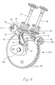
- each of the cam gear and lobe assemblies respectively actuate a pair of lifters pivotally mounted in each of the cylinder members.
- the cylinder members When the cylinder members are configured for a side valve or "L-head" engine, the cylinder members include intake and exhaust valves which are directly actuated by the lifters.
- the cylinder members When the cylinder members are configured for an OHV engine, the cylinder members include push rods which are actuated by the lifters, the push rods in turn actuating a valve assembly in the cylinder head, which includes rocker arms and intake and exhaust valves.
- the cylinder members which are configured for a side valve or "L-head" valve train and the cylinder members which are configured for an OHV valve train each include identical cam gear and lobe assemblies and identical lifter assemblies.
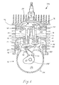
- the cam gears extend at least partially into the crankcase for driving engagement with a drive gear mounted to the crankshaft.
- the valve train for each of the foregoing configurations is identical between the crankshaft and the lifters, permitting the two types of cylinder members to be assembled to a crankcase in the same manner, and permitting the same crankcase to be used with either type of cylinder member.
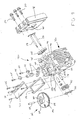
- Fig. 12 is a perspective view of components of the valve train within the cylinder member of Figs. 9-11;
- Fig. 13 is an exploded view of the crankcase, crankcase cover, and cylinder members of the engine of Figs. 1-7, showing the attachment of the crankcase cover and cylinder members to the crankcase, and further showing an exploded view of the breather assembly of one of the cylinder members;
- Fig. 14 is a partial perspective view of the engine of Figs. 1-7 in a vertical crankshaft orientation, showing a breather cover attached to a cylinder member, the cylinder cover including a breather hose fitting and ignition module supports;
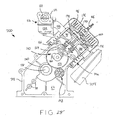
- Fig. 15 is a perspective view of a vertical crankshaft, V-twin engine according to the present invention, the engine including an overhead valve (“OHV”) valve train;
- OOV overhead valve
- Fig. 16 is a front elevational view of the engine of Fig. 15;
- Fig. 24 is a partial sectional view of the cylinder member and cylinder head assembly of Fig. 21;
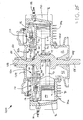
- Fig. 27 is a sectional view of a single cylinder, horizontal crankshaft engine including a cylinder member of the engine of Figs. 1-14, the engine having a vertical profile;
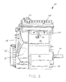
- crankcase 52 includes oil sump 62 therein, in which a quantity of lubricating oil is contained. Oil may be filled into crankcase 52 through oil fill opening 64 (Figs. 6 and 13) formed integrally with crankcase 52, to which oil fill conduit 66 may be attached. As shown in Fig. 6, oil fill conduit 66 is a tubular member formed of a suitable plastic material, and includes a removable oil fill cap 68. Referring to Fig. 7, a plurality of reinforced portions or bosses 70 are formed integrally within crankcase 52, which may be used as attachment points for attaching an output component to engine 50, such as a transmission or a working device, for example.
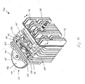
- crankcase 52 includes a pair of mounting surfaces 72a and 72b for attachment thereto of cylinder members 74a and 74b, respectively.
- Mounting surfaces 72b and 72b are shown disposed at a 90° angle with respect to one another, thereby positioning cylinder members 74a and 74b at a 90° angle with respect to one another.
- the angle between mounting surfaces 72b and 72b, and in turn the angle between cylinder members 74a and 74b may be varied as desired.
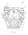
- crankshaft 58 includes flywheel 78 mounted to an end thereof which extends externally of crankcase cover 57.
- Flywheel 78 includes permanent magnet 80 disposed between fins 82 thereof.
- Electronic ignition modules 84 are connected one to each of cylinder members 74a and 74b as described below, and are positioned closely adjacent the outer periphery of flywheel 78 adjacent permanent magnet 80.
- Electronic ignition modules 84 are operably connected to spark plugs 86 of engine 50 by leads 88, shown in Figs. 1-4, such that rotation of flywheel 78 causes permanent magnet 80 to pass near each electronic ignition module 84 to induce an ignition spark in each spark plug 86 in a conventional manner.
- a starter (not shown) is attached to crankcase 52, and engages flywheel 78 to rotate crankshaft 58 for starting engine 50.
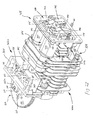
- cylinder members 74a and 74b each generally include a cylinder bore 90 for slidable receipt of a piston 91 therein, as well as mounting surfaces 92 for attachment to mounting surfaces 74b and 74b of crankcase 52, and upper attachment faces 94 for attachment thereto of cylinder heads 96.
- cylinder heads 96 may be integrally formed with cylinder members 74a and 74b.
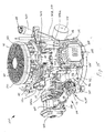
- shroud 126 is attached to crankcase 52 and cylinder members 74b and 74b, and substantially covers the front side of crankcase 52, including flywheel 78, and also the front side of cylinder members 74b and 74b.
- Air inlet screen 132 is attached to shroud, and may cover a recoil starter mechanism (not shown) attached to crankshaft 52 in applications where engine 50 does not include an electric starter motor.
- Air inlet screen 132 includes a plurality of louvers 134 therein into which intake air may be drawn by flywheel 78 into the area between crankcase 52 and shroud 128, which intake air is directed by shroud 128 to the air cleaner cavity beneath air cleaner cover 130 for combustion within engine 50. Also, air may be directed by shroud 128 and cylinder wraps 136 around cylinder members 74b and 74b for cooling same during running of engine 50.
- valve seats 180 which may be integrally cast into cylinder members 74b and 74b.
- valve seats 180 may be formed as separate components which are press-fitted into cylinder members 74b and 74b, as shown in Figs. 9 and 11.
- Valve springs 182 are coiled about each of intake and exhaust valves 174 and 176 under compression between spring seats 184 (Fig. 11) of cylinder members 74b and 74b and valve keepers 186, and normally bias intake and exhaust valves 174 and 176 to a closed position wherein intake and exhaust valves 174 and 176 are seated against valve seats 180.
Landscapes
- Engineering & Computer Science (AREA)
- Mechanical Engineering (AREA)
- General Engineering & Computer Science (AREA)
- Chemical & Material Sciences (AREA)
- Combustion & Propulsion (AREA)
- Valve-Gear Or Valve Arrangements (AREA)
- Cylinder Crankcases Of Internal Combustion Engines (AREA)
Abstract
Description
Claims (12)
- A twin cylinder internal combustion engine (50, 300), characterized by a crankcase (52) having a crankshaft (58) rotatably disposed therein; a pair of cylinder members (74a, 74b) mounted to said crankcase, said cylinder members and said crankcase being separate components; and a valve train (110, 322) including a pair of cam gears (156) supported respectively by said cylinder members, at least a portion of each said cam gear extending into said crankcase for driving engagement with said crankshaft; at least one cam lobe (160) associated with each said cam gear; and at least one lifter (164) pivotally mounted within each said cylinder member, each said lifter in engagement with a respective said cam lobe.
- The internal combustion engine (50, 300) of Claim 1, characterized in that each said cylinder member (74a, 74b) includes a pair of said lifters (164), and each said cam gear (156) includes a pair of said cam lobes (160), each said cam lobe actuating a respective said lifter.
- The internal combustion engine (50) of Claim 2, characterized in that each said cylinder member (74a, 74b) includes a cylinder bore (90) therein, and intake and exhaust valves (174, 176) actuated respectively by said lifters (164), wherein in each said cylinder member, said intake and exhaust valves are disposed radially adjacent said cylinder bore.
- The internal combustion engine (300) of Claim 2, characterized in that each said cylinder member (74a, 74b) includes a cylinder bore (90) therein, and a pair of push rods (350) actuated respectively by said lifters (164), wherein in each said cylinder member, said push rods are disposed radially adjacent said cylinder bore.
- The internal combustion engine (50, 300) of any of the preceding claims, characterized by a cylinder head (96, 324) attached to each said cylinder member (74a, 74b), each said cylinder member and cylinder head defining a combustion chamber (190) therebetween.
- The internal combustion engine (300) of Claim 4, characterized by each said cylinder member (74a, 74b) further including a cylinder head (324), each said cylinder head including an intake valve (174); an exhaust valve (176); and a pair of rocker arms (346) for respectively actuating said intake and exhaust valves in response to movement of said push rods (350).
- The internal combustion engine (50, 300) of any of the preceding claims, characterized by a drive gear (150) mounted to said crankshaft (58), said drive gear in meshing engagement with each of said cam gears (156).
- The internal combustion engine (50, 300) of any of the preceding claims, characterized in that one of said cam gear (156) and lobes (160) faces in a first direction, and the other of said cam gear (156) and lobes (160) faces in a second direction opposite said first direction.
- A method of assembling the internal combustion engine (50, 300) of any of the preceding claims, characterized by the steps of:assembling said cam gear (156), said at least one cam lobe (160), and said at least one lifter (164) to each of said cylinder members (74a, 74b); andthen securing said cylinder members to said crankcase (52).
- The method of Claim 9, characterized by, before said securing step, the additional step of positioning each said cylinder member (74a, 74b) with respect to said crankcase (52) such that at least a portion of said cam gear (156) thereof extends into said crankcase.
- The method of Claims 9 or 10, characterized in that said assembling step further comprises one of:assembling at least one valve (174, 176) to each cylinder member (74a, 74b); orassembling at least one push rod (350) to each cylinder member.
- The method of any of Claims 9-11, characterized by the additional step of securing a cylinder head (96, 324) to each said cylinder member (74a, 74b).
Applications Claiming Priority (6)
| Application Number | Priority Date | Filing Date | Title |
|---|---|---|---|
| 2001-02-02 | |||
| US37256002P | 2002-04-15 | 2002-04-15 | |
| US372560P | 2002-04-15 | ||
| US40284102P | 2002-08-12 | 2002-08-12 | |
| US402841P | 2002-08-12 | ||
| US10/409,262 US6941914B2 (en) | 2002-04-15 | 2003-04-08 | Internal combustion engine |
Publications (2)
| Publication Number | Publication Date |
|---|---|
| EP1357276A2 true EP1357276A2 (en) | 2003-10-29 |
| EP1357276A3 EP1357276A3 (en) | 2003-12-03 |
Family
ID=29716107
Family Applications (1)
| Application Number | Title | Priority Date | Filing Date |
|---|---|---|---|
| EP03008644A Withdrawn EP1357276A3 (en) | 2002-04-15 | 2003-04-15 | Internal combustion engine |
Country Status (2)
| Country | Link |
|---|---|
| US (2) | US6941914B2 (en) |
| EP (1) | EP1357276A3 (en) |
Families Citing this family (25)
| Publication number | Priority date | Publication date | Assignee | Title |
|---|---|---|---|---|
| JP2005120973A (en) * | 2003-10-20 | 2005-05-12 | Kawasaki Heavy Ind Ltd | Vertical engine |
| US7287494B2 (en) | 2004-11-10 | 2007-10-30 | Buck Supply Co., Inc. | Multicylinder internal combustion engine with individual cylinder assemblies and modular cylinder carrier |
| US7287493B2 (en) | 2004-11-10 | 2007-10-30 | Buck Supply Co., Inc. | Internal combustion engine with hybrid cooling system |
| US7543558B2 (en) | 2004-11-10 | 2009-06-09 | Buck Diesel Engines, Inc. | Multicylinder internal combustion engine with individual cylinder assemblies |
| US20060156711A1 (en) * | 2005-01-20 | 2006-07-20 | Carpenter Todd L | Internal combustion engine with secondary air pump for catalyst |
| US7267326B2 (en) | 2005-05-05 | 2007-09-11 | Tecumseh Products Company | Automatic priming system |
| US20070034431A1 (en) * | 2005-08-09 | 2007-02-15 | Jackson Vincent E | Governor guard |
| US20070251512A1 (en) * | 2006-04-28 | 2007-11-01 | Caterpillar Inc. | Integrated check valve breather |
| US7559299B2 (en) * | 2007-01-19 | 2009-07-14 | Eastway Fair Company Limited | Monolithic cylinder-crankcase |
| DE102007012734A1 (en) * | 2007-03-16 | 2008-09-18 | Schaeffler Kg | Rocker arm for valve gear of internal combustion engine in e.g. two-wheeler, has axle bearing integrated in crossbar, formed as half-shell and aligned with opening, where half shell has uniform radius, which is adapted to radius of openings |
| US7685975B2 (en) * | 2007-12-22 | 2010-03-30 | Springer Joseph E | Internal combustion engine twin power unit having an oscillating cylinder |
| US20090206081A1 (en) * | 2008-02-18 | 2009-08-20 | Snyder Dale D | System and Method for Inhibiting Vaporization from Liquids |
| US7814879B2 (en) * | 2008-04-23 | 2010-10-19 | Techtronic Outdoor Products Technology Limited | Monolithic block and valve train for a four-stroke engine |
| US20090293822A1 (en) * | 2008-05-28 | 2009-12-03 | Honda Motor Co., Ltd. | General-purpose v-type engine |
| CN201372851Y (en) * | 2009-01-06 | 2009-12-30 | 常柴股份有限公司 | V-shaped water-cooled diesel engine |
| US8316814B2 (en) * | 2009-06-29 | 2012-11-27 | Buck Kenneth M | Toploading internal combustion engine |
| USD631895S1 (en) * | 2009-10-30 | 2011-02-01 | Kohler Co. | Snow engine |
| US8943797B2 (en) | 2010-01-15 | 2015-02-03 | GM Global Technology Operations LLC | Cylinder head with symmetric intake and exhaust passages |
| US8528510B2 (en) * | 2010-01-15 | 2013-09-10 | GM Global Technology Operations LLC | Intake manifold |
| US9103305B2 (en) * | 2010-01-15 | 2015-08-11 | GM Global Technology Operations LLC | Internal combustion engine |
| US8714295B2 (en) * | 2010-01-15 | 2014-05-06 | GM Global Technology Operations LLC | Internal combustion engine and vehicle packaging for same |
| JP5525993B2 (en) * | 2010-10-26 | 2014-06-18 | 川崎重工業株式会社 | Cylinder cooling device for air-cooled engine |
| US8893690B2 (en) | 2012-05-10 | 2014-11-25 | Caterpillar Inc. | Check valve for an engine breather assembly |
| US10605164B2 (en) | 2017-06-29 | 2020-03-31 | Robert Verne Loomis | Engine assembly including cam for Z-type engines |
| US11066962B1 (en) * | 2020-07-13 | 2021-07-20 | Caterpillar Inc. | Engine valve actuation system and lifter arm assembly having lifter arm oil spray port for cam-roller lubrication |
Family Cites Families (78)
| Publication number | Priority date | Publication date | Assignee | Title |
|---|---|---|---|---|
| USRE21750E (en) * | 1941-03-11 | Internal combustion engine | ||
| US872571A (en) * | 1906-12-14 | 1907-12-03 | Fritz Moser | Internal-combustion engine. |
| US1155044A (en) * | 1913-01-31 | 1915-09-28 | Mary Elizabeth Johnson | Valve-controlling mechanism for internal-combustion engines. |
| US1087803A (en) * | 1913-04-24 | 1914-02-17 | Anthony Doerfler | Timing device. |
| US1874195A (en) * | 1928-10-31 | 1932-08-30 | King Albert Bentley | Internal combustion engine |
| US1873945A (en) * | 1930-03-29 | 1932-08-23 | Ig Farbenindustrie Ag | Materials coated with lacquers, lacquers, and a process of producing coatings |
| US2041979A (en) * | 1933-08-14 | 1936-05-26 | Atlas Diesel Ab | Means for anchoring cylinders in engines with angularly disposed cylinders |
| US2218332A (en) * | 1939-04-10 | 1940-10-15 | Leonard E Fowler | Internal combustion engine |
| US2419630A (en) * | 1943-01-07 | 1947-04-29 | United Aircraft Prod | Thermostatic surge valve |
| US2491630A (en) * | 1946-08-05 | 1949-12-20 | Compact Power Products Inc | Engine constructed of sections bolted together along vertical plane to form an entire head, block, and crankcase thereof |
| US2671436A (en) * | 1950-04-08 | 1954-03-09 | Massey Harris Co Ltd | Multiform internal-combustion engine |
| DE944640C (en) | 1953-03-14 | 1956-06-21 | Kloeckner Humboldt Deutz Ag | Internal combustion engine |
| US2980989A (en) * | 1956-12-20 | 1961-04-25 | Int Harvester Co | Process for constructing and balancing engines |
| US3386301A (en) * | 1964-09-16 | 1968-06-04 | Koyama Mikio | Camshaft driving system for internal combustion engines |
| US3561416A (en) * | 1969-04-25 | 1971-02-09 | Kiekhaefer Elmer Carl | Internal combustion engine cylinder block |
| SE7606826L (en) * | 1976-06-16 | 1977-12-17 | Volvo Penta Ab | DEVICE FOR MOLDED FRAMES FOR HYDROCOLDED TWO-STEP ENGINES |
| US4135478A (en) * | 1976-10-20 | 1979-01-23 | Rassey Louis J | Modular engine construction |
| US4198947A (en) * | 1976-10-20 | 1980-04-22 | Rassey Louis J | Modular engine construction |
| JPS5392012A (en) * | 1977-01-24 | 1978-08-12 | Kubota Ltd | V shaped forced-air cooling 4 cycle engine |
| JPS5392054A (en) * | 1977-01-24 | 1978-08-12 | Kubota Ltd | Forced air-cooled contactless ignition system v-type engine |
| US4198847A (en) * | 1977-09-15 | 1980-04-22 | Applied Power Inc. | Base for a hydraulically operated tool |
| US4219103A (en) * | 1978-07-03 | 1980-08-26 | Leyman Manufacturing Corp. | Elevator platform structure |
| AT380066B (en) | 1980-01-16 | 1986-04-10 | Jenbacher Werke Ag | PISTON MACHINE |
| US4380216A (en) * | 1980-09-17 | 1983-04-19 | Tecumseh Products Company | Economical engine construction |
| JPS6181572A (en) * | 1984-09-28 | 1986-04-25 | Kawasaki Heavy Ind Ltd | Vertical shaft v-engine |
| US4662322A (en) * | 1984-11-26 | 1987-05-05 | Kawasaki Jukogyo Kabushiki Kaisha | Overhead-valve engine |
| US4756280A (en) * | 1984-12-21 | 1988-07-12 | Kawasaki Jukogyo Kabushiki Kaisha | Cooling system for vertical shaft V-type engine |
| US4862981A (en) * | 1984-12-24 | 1989-09-05 | Kawasaki Jukogyo Kabushiki Kaisha | Internal combustion engine and devices employing same |
| JPS61265341A (en) * | 1985-05-17 | 1986-11-25 | Kawasaki Heavy Ind Ltd | Cylinder block structure in v-type engine |
| US4681067A (en) * | 1985-06-12 | 1987-07-21 | Kawasaki Jukogyo Kabushiki Kaisha | Liquid-cooled engine of the vertical shaft type |
| US4697557A (en) * | 1985-06-18 | 1987-10-06 | Kawasaki Jukogyo Kabushiki Kaisha | V-type internal combustion engine |
| US4714060A (en) * | 1986-02-04 | 1987-12-22 | R K W Industries, Inc. | Composite engine |
| JPS63154851A (en) * | 1986-12-16 | 1988-06-28 | Kawasaki Heavy Ind Ltd | Manifold for v-type engine and manufacture thereof |
| JPH045725Y2 (en) * | 1987-12-17 | 1992-02-18 | ||
| US4857078A (en) * | 1987-12-31 | 1989-08-15 | Membrane Technology & Research, Inc. | Process for separating higher hydrocarbons from natural or produced gas streams |
| FR2629865A1 (en) | 1988-04-11 | 1989-10-13 | Meney Regis | Compact modular multi-cylinder two-stroke engine |
| JPH0233405A (en) * | 1988-07-22 | 1990-02-02 | Yamaha Motor Co Ltd | V type multiple cylinder engine |
| JPH0242139A (en) | 1988-08-03 | 1990-02-13 | Yamaha Motor Co Ltd | Engine |
| USD308872S (en) * | 1988-08-12 | 1990-06-26 | Briggs & Stratton Corporation | Internal combustion engine |
| USD308871S (en) * | 1988-08-12 | 1990-06-26 | Briggs & Stratton Corporation | Internal combustion engine |
| US4936263A (en) * | 1989-02-24 | 1990-06-26 | Kawasaki Jukogyo Kabushiki Kaisha | V-type engine having different explosion intervals |
| US4930476A (en) * | 1989-07-19 | 1990-06-05 | Yamaha Hatsudoki Kabushiki | Governor for vertical v-type engine |
| EP0425899B1 (en) * | 1989-11-02 | 1994-01-26 | Kubota Corporation | Engine with mechanical governor and decompression device |
| USD343843S (en) * | 1991-04-15 | 1994-02-01 | Honda Giken Kogyo K.K. | Internal combustion engine |
| US5241781A (en) * | 1991-08-19 | 1993-09-07 | Malczyk Thomas R | House plant hospital |
| JPH05335813A (en) | 1992-05-29 | 1993-12-17 | Showa Electric Wire & Cable Co Ltd | Cable |
| US5235942A (en) * | 1992-12-23 | 1993-08-17 | Kohler Co. | Cylinder head assembly |
| US5293847A (en) * | 1993-02-16 | 1994-03-15 | Hoffman Ronald J | Powdered metal camshaft assembly |
| US5357917A (en) * | 1993-02-23 | 1994-10-25 | Ryobi Outdoor Products, Inc. | Stamped cam follower and method of making a stamped cam follower |
| US5341781A (en) * | 1993-10-18 | 1994-08-30 | Kohler Co. | Reduced component internal combustion engine |
| WO1996024758A1 (en) * | 1995-02-08 | 1996-08-15 | Yanmar Diesel Engine Co., Ltd. | V type diesel engine |
| IL114746A (en) * | 1995-07-26 | 1998-12-27 | Israel State | Apparatus for and method of controlling and calibrating the phase of a coherent signal |
| TW487770B (en) * | 1995-12-15 | 2002-05-21 | Honda Motor Co Ltd | Lubricating system in a 4-stroke engine |
| US5647337A (en) * | 1996-02-21 | 1997-07-15 | Kohler Co. | Engine breather device with cooling baffle |
| US5823156A (en) * | 1997-04-09 | 1998-10-20 | Kohler Co. | Dual bore intake manifold |
| US5887678A (en) * | 1997-06-19 | 1999-03-30 | Briggs & Stratton Corporation | Lubrication apparatus for shaft bearing |
| US5813384A (en) * | 1997-08-20 | 1998-09-29 | Briggs & Stratton Corporation | Intake system arrangement for V-type engine |
| US5950579A (en) * | 1998-01-05 | 1999-09-14 | Ott; Vern D. | Internal combustion engine |
| USD421024S (en) * | 1998-07-23 | 2000-02-22 | Honda Giken Kogyo Kabushiki Kaisha | Internal-combustion engine |
| JP2000120651A (en) * | 1998-10-20 | 2000-04-25 | Honda Motor Co Ltd | V-type engine |
| US6105548A (en) * | 1998-11-03 | 2000-08-22 | Briggs & Stratton Corporation | Mounting apparatus for an engine and transmission |
| US6213072B1 (en) * | 1998-11-27 | 2001-04-10 | Honda Giken Kogyo Kabushiki Kaisha | V-shaped internal combustion engine |
| GB2344378A (en) | 1998-12-05 | 2000-06-07 | Rover Group | Modular i.c. engine |
| US6109221A (en) * | 1999-02-17 | 2000-08-29 | Kohler Co. | Engine with integral coolant pump |
| US6145479A (en) * | 1999-02-18 | 2000-11-14 | Kohler Co. | Vertical shaft engine cooling apparatus |
| US6295959B1 (en) * | 1999-03-19 | 2001-10-02 | Tecumseh Products Company | External drive double shaft overhead cam engine |
| US6343576B1 (en) * | 1999-10-15 | 2002-02-05 | Honda Giken Kogyo Kabushiki Kaisha | Overhead camshaft V-2 engine |
| JP3827494B2 (en) * | 1999-11-04 | 2006-09-27 | 本田技研工業株式会社 | V-type 2-cylinder engine |
| AU143889S (en) * | 2000-01-17 | 2001-05-15 | Honda Giken Kogyo Kk Honda Motor Co Ltd | Internal combustion engine |
| US6349688B1 (en) * | 2000-02-18 | 2002-02-26 | Briggs & Stratton Corporation | Direct lever overhead valve system |
| US7000577B2 (en) * | 2000-02-29 | 2006-02-21 | Brp-Rotax Gmbh & Co. Kg | Modular engine family |
| JP3803526B2 (en) | 2000-03-16 | 2006-08-02 | 本田技研工業株式会社 | Side valve engine |
| US6422194B2 (en) * | 2000-03-16 | 2002-07-23 | Honda Giken Kogyo Kabushiki Kaisha | Handheld type four-cycle engine |
| US6354249B1 (en) * | 2000-06-13 | 2002-03-12 | Kohler Co. | Engine with coolant pump |
| JP3401489B2 (en) * | 2000-08-30 | 2003-04-28 | 川崎重工業株式会社 | Radiator device for engine |
| JP3420191B2 (en) * | 2000-08-31 | 2003-06-23 | 川崎重工業株式会社 | Water-cooled V-type two-cylinder engine |
| WO2002025082A2 (en) | 2000-09-25 | 2002-03-28 | Bombardier-Rotax Gmbh & Co. Kg | Modular engine family |
| US6595167B2 (en) * | 2001-05-22 | 2003-07-22 | Mtd Products Inc | Internal combustion engine and method of making the same |
-
2003
- 2003-04-08 US US10/409,262 patent/US6941914B2/en not_active Expired - Fee Related
- 2003-04-15 EP EP03008644A patent/EP1357276A3/en not_active Withdrawn
-
2005
- 2005-03-10 US US11/076,822 patent/US20050150474A1/en not_active Abandoned
Also Published As
| Publication number | Publication date |
|---|---|
| US6941914B2 (en) | 2005-09-13 |
| US20040025823A1 (en) | 2004-02-12 |
| EP1357276A3 (en) | 2003-12-03 |
| US20050150474A1 (en) | 2005-07-14 |
Similar Documents
| Publication | Publication Date | Title |
|---|---|---|
| US6941914B2 (en) | Internal combustion engine | |
| EP1201883B1 (en) | Mid cam engine | |
| EP0279445B1 (en) | Vertical engine for walk-behind lawn mower | |
| EP0835987B1 (en) | Lubricating system in 4-cycle engine | |
| US6904883B2 (en) | Modular internal combustion engines | |
| US5031591A (en) | OHC vertical crankshaft engine | |
| US7201132B2 (en) | Combustion engine of vertical shaft type | |
| CA2472431C (en) | Four-stroke engine system | |
| EP1039099B1 (en) | Drive train for overhead cam engine | |
| NZ260499A (en) | Four-stroke ic engine; operates with combustible mixture of air, fuel and lubricating oil added via crankcase | |
| CN1678826A (en) | Internal combustion engine inverted crankcase with accessories | |
| EP1039098B1 (en) | External drive double shaft overhead cam engine (dschc) | |
| JP3231201B2 (en) | OHC type engine lubrication system | |
| AU2003200621B2 (en) | Mid cam engine | |
| JP2006514208A (en) | 4-cycle engine | |
| US7104252B1 (en) | Crankcase venting rotary valve carburetor | |
| AU2003203730A1 (en) | Internal combustion engine | |
| US11384711B2 (en) | Engine | |
| JPH0380963B2 (en) | ||
| JP3414035B2 (en) | Air-cooled 4-cycle engine cylinder cooling system | |
| JPH09151746A (en) | V-type diesel engine | |
| JP3730363B2 (en) | Single cylinder water-cooled engine | |
| JP4412814B2 (en) | Horizontal internal combustion engine | |
| JPS641444Y2 (en) | ||
| JPS6332343Y2 (en) |
Legal Events
| Date | Code | Title | Description |
|---|---|---|---|
| PUAI | Public reference made under article 153(3) epc to a published international application that has entered the european phase |
Free format text: ORIGINAL CODE: 0009012 |
|
| PUAL | Search report despatched |
Free format text: ORIGINAL CODE: 0009013 |
|
| AK | Designated contracting states |
Kind code of ref document: A2 Designated state(s): AT BE BG CH CY CZ DE DK EE ES FI FR GB GR HU IE IT LI LU MC NL PT RO SE SI SK TR |
|
| AX | Request for extension of the european patent |
Extension state: AL LT LV MK |
|
| AK | Designated contracting states |
Kind code of ref document: A3 Designated state(s): AT BE BG CH CY CZ DE DK EE ES FI FR GB GR HU IE IT LI LU MC NL PT RO SE SI SK TR |
|
| AX | Request for extension of the european patent |
Extension state: AL LT LV MK |
|
| 17P | Request for examination filed |
Effective date: 20040527 |
|
| AKX | Designation fees paid |
Designated state(s): AT BE BG CH CY CZ DE DK EE ES FI FR GB GR HU IE IT LI LU MC NL PT RO SE SI SK TR |
|
| 17Q | First examination report despatched |
Effective date: 20061121 |
|
| GRAP | Despatch of communication of intention to grant a patent |
Free format text: ORIGINAL CODE: EPIDOSNIGR1 |
|
| RIN1 | Information on inventor provided before grant (corrected) |
Inventor name: DOPKE, RUSSELL J. Inventor name: GLODOWSKI, MARK J. Inventor name: MONIS, KARL W. Inventor name: STANELLE, GARY Inventor name: KOEHLER, SCOT A. Inventor name: IMMEL, THOMAS A. Inventor name: SNYDER, DALE D. |
|
| STAA | Information on the status of an ep patent application or granted ep patent |
Free format text: STATUS: THE APPLICATION IS DEEMED TO BE WITHDRAWN |
|
| 18D | Application deemed to be withdrawn |
Effective date: 20070824 |